US6324322B1 - Fused-fiber multi-window wavelength filter using unbalanced Michelson Interferometer - Google Patents
Fused-fiber multi-window wavelength filter using unbalanced Michelson Interferometer Download PDFInfo
- Publication number
- US6324322B1 US6324322B1 US09/327,148 US32714899A US6324322B1 US 6324322 B1 US6324322 B1 US 6324322B1 US 32714899 A US32714899 A US 32714899A US 6324322 B1 US6324322 B1 US 6324322B1
- Authority
- US
- United States
- Prior art keywords
- fiber
- mwf
- fibers
- optic
- output
- Prior art date
- Legal status (The legal status is an assumption and is not a legal conclusion. Google has not performed a legal analysis and makes no representation as to the accuracy of the status listed.)
- Expired - Fee Related
Links
Images
Classifications
-
- G—PHYSICS
- G02—OPTICS
- G02B—OPTICAL ELEMENTS, SYSTEMS OR APPARATUS
- G02B6/00—Light guides; Structural details of arrangements comprising light guides and other optical elements, e.g. couplings
- G02B6/24—Coupling light guides
- G02B6/26—Optical coupling means
- G02B6/28—Optical coupling means having data bus means, i.e. plural waveguides interconnected and providing an inherently bidirectional system by mixing and splitting signals
- G02B6/293—Optical coupling means having data bus means, i.e. plural waveguides interconnected and providing an inherently bidirectional system by mixing and splitting signals with wavelength selective means
- G02B6/29331—Optical coupling means having data bus means, i.e. plural waveguides interconnected and providing an inherently bidirectional system by mixing and splitting signals with wavelength selective means operating by evanescent wave coupling
- G02B6/29332—Wavelength selective couplers, i.e. based on evanescent coupling between light guides, e.g. fused fibre couplers with transverse coupling between fibres having different propagation constant wavelength dependency
-
- G—PHYSICS
- G02—OPTICS
- G02B—OPTICAL ELEMENTS, SYSTEMS OR APPARATUS
- G02B6/00—Light guides; Structural details of arrangements comprising light guides and other optical elements, e.g. couplings
- G02B6/24—Coupling light guides
- G02B6/26—Optical coupling means
- G02B6/28—Optical coupling means having data bus means, i.e. plural waveguides interconnected and providing an inherently bidirectional system by mixing and splitting signals
- G02B6/293—Optical coupling means having data bus means, i.e. plural waveguides interconnected and providing an inherently bidirectional system by mixing and splitting signals with wavelength selective means
- G02B6/29346—Optical coupling means having data bus means, i.e. plural waveguides interconnected and providing an inherently bidirectional system by mixing and splitting signals with wavelength selective means operating by wave or beam interference
- G02B6/2935—Mach-Zehnder configuration, i.e. comprising separate splitting and combining means
- G02B6/29352—Mach-Zehnder configuration, i.e. comprising separate splitting and combining means in a light guide
- G02B6/29355—Cascade arrangement of interferometers
-
- G—PHYSICS
- G02—OPTICS
- G02B—OPTICAL ELEMENTS, SYSTEMS OR APPARATUS
- G02B6/00—Light guides; Structural details of arrangements comprising light guides and other optical elements, e.g. couplings
- G02B6/24—Coupling light guides
- G02B6/26—Optical coupling means
- G02B6/28—Optical coupling means having data bus means, i.e. plural waveguides interconnected and providing an inherently bidirectional system by mixing and splitting signals
- G02B6/2804—Optical coupling means having data bus means, i.e. plural waveguides interconnected and providing an inherently bidirectional system by mixing and splitting signals forming multipart couplers without wavelength selective elements, e.g. "T" couplers, star couplers
- G02B6/2821—Optical coupling means having data bus means, i.e. plural waveguides interconnected and providing an inherently bidirectional system by mixing and splitting signals forming multipart couplers without wavelength selective elements, e.g. "T" couplers, star couplers using lateral coupling between contiguous fibres to split or combine optical signals
Definitions
- the present invention relates to optical filters and, in particular, to multi-window wavelength filters using fused-fiber unbalanced Michelson Interferometers.
- WDMs wavelength division multiplexers
- the use of WDMs provides a simple and economical way to increase the transmission capacity of fiber optic communication systems by allowing multiple wavelengths to be transmitted and received over a single optical fiber through signal wavelength multiplexing and demultiplexing. The demultiplexed signals can then be routed to the final destinations.
- WDMs can be used in fiber optic communication systems for other purposes as well, such as dispersion compensation, noise reduction, and gain flatting, i.e., maintaining a uniform gain within the usable bandwidth for erbium-doped amplifiers.
- WDMs can be manufactured using, for example, biconical tapered fusion (BTF) technology.
- BTF biconical tapered fusion
- two optical fibers are fused together along an interior portion to form a fused-fiber coupler, so that light of two wavelengths (i.e., 1310 nm and 1550 nm) entering the input terminals of the first and second fibers, respectively, are multiplexed onto a single fiber.
- the coupling ratios for the two channels exhibit complementary sinusoidal behavior for amplitude as a function of frequency within the passband of the WDM, with each channel having one or more peaks (or windows) within the passband.
- Information carried by the two signals along the single fiber is then demultiplexed at the WDM outputs.
- Multi-window WDMs have two or more peaks of amplitude as a function of frequency (or operational windows) for each channel within a passband.
- MWDMs can also be made using BTF technology by twisting two optical fibers together, fusing the center portion together, and pulling the fibers until a desired multi-window transmission spectrum appears at a monitored fiber output terminal.
- BTF technology Such a long-tapered-fusing technology is discussed in commonly-owned U.S. Pat. No. 5,809,190, entitled “Apparatus and Method of Making a Fused Dense Wavelength-Division Multiplexer”, which is incorporated by reference herein in its entirety.
- One essential component of multiplexing and demultiplexing multiple signals is the ability to accurately separate the individual signals of different wavelengths from the combined signal.
- Many techniques for demultiplexing wavelength-multiplexed signals have been developed and proposed.
- One conventional method uses prisms and diffraction gratings to spatially separate signals of different wavelengths from a fiber. These devices suffer from lack of programmability and flexibility, poor switching performance, and the difficulty of integration. Moreover, such systems often require precision positioning of various components to ensure desired optical alignment for proper operation.
- optical bandpass filters that selectively pass an optical beam of a specified wavelength.
- the optical filter is capable of selecting and separating any desired wavelength out of a wavelength division multiplexed optical signal.
- a large number of information signals are multiplexed on a single optical fiber, and such a very large number of optical filters, each having its own passband and a central passband wavelength, are needed in order to demultiplex the optical signals or to switch the connection of the optical channels.
- optical filter The underlying principle behind the operation of some optical filters is multi-beam optical interference.
- the optical path length of the individual light beams in the device is varied, after which the beams are interfered. Since the effective path length is wavelength dependent, it follows that the interference is wavelength dependent, which yields a wavelength dependent optical response.
- Each filter can be tuned to pass signals at a desired wavelength, while attenuating or blocking signals at all other wavelengths.
- the optical filters for use in the optical telecommunication network have been formed based upon a multi-layer mirror or a Fabry-Perot resonator.
- the passband wavelength has been determined by the construction of the filter such as the geometrical dimension or the composition of the material.
- LCTFs liquid crystal tunable filters
- AOTFs acousto-optical tunable filters
- reflective waveguide arrays These and other types of optical filters can also be difficult to tune and/or subject to external influences such as temperature, movement, etc.
- the passband should contain as many communication channels or windows as possible, subject to constraints with the system.
- the bandwidth of each channel or window and/or the separation between wavelength peaks should be minimized. Separating signals passed through MWDMs can be accomplished with tunable multi-window wavelength filters. However, as the number of channels within a passband increases, it becomes more difficult for the multi-window wavelength filter to separate or filter the various wavelengths.
- the present invention provides a multi-window wavelength filter (MWF) using an unbalanced Michelson Interferometer, where the MWF is used to construct multi-window wavelength division multiplexers (MWDMs) and dense WDMs that are smaller sized and tunable to desired wavelengths.
- MPF multi-window wavelength filter
- a MWF is formed from a fused-fiber coupler with the two fibers that carry the decoupled input signals having an optical path length difference and ends that are coated with a highly reflective coating.
- Input light entering one fiber of the MWF is decoupled after it exits the coupling region.
- the two signals then travel along the two fibers until they reach the reflective coating.
- the light is reflected back toward the coupling region, where interference occurs between the two signals from the two fibers, and exits the coupling region and then the MWF output.
- the path length difference results in constructive and destructive interference of the light as it travels through the coupling region, resulting in complementary signals at output of the coupling region.
- the signal taken at the MWF output can be adjusted by changing the optical path length to obtain a desired signal at a particular wavelength.
- the optical path length can be changed by changing the relative lengths and/or the refractive indexes of the fibers or portions thereof, or a combination of the two.
- an MWDM is used to form an MWDM in several different ways.
- an MWDM is formed with two essentially identical MWFs coupled (e.g., spliced) to a 3-dB coupler.
- the output of the MWDM is taken at complementary fibers of the two MWFs, resulting in multiple channels within a given wavelength.
- the channel separation can be changed, which changes the number of channels in the wavelength, by varying the optical path length difference of the two MWFs.
- an MWDM is formed with an optical circulator coupled (e.g., spliced) to a single MWF.
- a high isolation MWDM i.e., one with cross-talk reduction of adjacent and neighboring channels
- a high isolation MWDM can be constructed by coupling an MWDM to two additional MWFs having the same channel separation to suppress sidelobes of adjacent Or neighboring channels.
- Other aspects of the invention include forming a dense WDM (DWDM) by cascading MWDMs formed from the MWF of the present invention.
- DWDM dense WDM
- Temperature-induced refractive index or optical path length changes in the MWF can be compensated for by maintaining the optical path length difference as temperature increases.
- One type of passive thermal compensation (PTC) technique adjusts the length and/or the refractive index of the two fibers so that a temperature induced refractive index change in one fiber offsets the temperature induced refractive index change in the other fiber.
- Another PTC technique secures a composite substrate to both fibers, where the composite substrate has different thermal expansion rates at the places where the substrate is secured to the fibers. Thus, as temperature changes, different amounts of tension are applied to each fiber, thereby compensating the effects of temperature on the refractive index.
- Yet another PTC technique secures a substrate to one of the fibers. The substrate is such that as temperature changes, the substrate expands or contracts to provide the necessary tension increase or decrease to compensate for the changes of the refractive indexes.
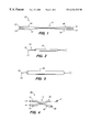
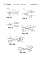
- FIG. 1 shows a conventional fused-fiber coupler
- FIG. 2 shows the fused-fiber coupler of FIG. 1 mounted in a quartz sleeve
- FIG. 3 shows the coupler and sleeve of FIG. 2 enclosed in a protective package
- FIG. 4 shows an unbalanced multi-window wavelength filter (MWF) according to the present invention
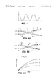
- FIG. 5 shows a typical transmission spectrum at the output of the MWF of FIG. 4;
- FIGS. 6A and 6B show different ways of changing the optical path length of the MWF of FIG. 4;
- FIG. 6C shows a general relationship between the change of refractive index as a function of UV exposure time for various UV intensities
- FIG. 7A shows a bandpass filter formed from cascading the MWFs of FIG. 4 according to one embodiment of the present invention
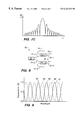
- FIG. 7B shows the spectrum of various MWFs of the bandpass filter of FIG. 7 A and the power transfer function of the bandpass filter of FIG. 7A;
- FIG. 7C shows a more detailed spectrum at the output of the bandpass filter of FIG. 7A
- FIG. 8 shows a multi-window wavelength division multiplexer (MWDM) using the MWF of FIG. 4 according to one embodiment
- FIG. 9 shows a typical transmission spectrum at the output of the MWDM of FIG. 8;
- FIG. 10 shows an MWDM using the MWF of FIG. 4 and an optical circulator according to another embodiment
- FIG. 11 shows a high isolation MWDM according to one embodiment
- FIG. 12 shows a dense WDM according to one embodiment
- FIGS. 13A-13C show different types of passive thermal compensation for the MWF of FIG. 4 .
- the present invention provides a multi-window wavelength filter (MWF) formed from a fused fiber coupler, where the two fibers at one end of the coupler have different optical path lengths and both fibers have highly reflective coatings at the fiber ends. Broadband light entering the MWF is reflected back out of the MWF, with the two decoupled light signals exhibiting a complementary spectrum due to the optical path length difference. By varying the optical path length difference, the output of the MWF can be adjusted to select a signal at a desired wavelength.
- MMF multi-window wavelength filter
- Biconical tapered fusion (BTF) technology has been used to fabricate a variety of optical fiber devices, such as couplers, attenuators, filters, and wideband wavelength division multiplexers (WDMs).
- a typical fused-fiber coupler 10 is shown in FIG. 1 .
- Fused-fiber coupler 10 can be formed by heating and axially stretching two optic fibers to form a coupling region 11 .
- the resulting coupler 10 has two input ports 12 and 13 and two output ports 16 and 17 , capable of coupling a wide range of wavelengths.
- Coupler 10 divides the power of light entering input port 12 , so that a fraction ⁇ of light from input port 12 is transmitted out of output port 16 and the remaining fraction 1 ⁇ of light from input port 12 is transmitted out of output port 17 .
- a fraction 1 ⁇ of light from input port 13 is transmitted out of output port 16
- the remaining fraction ⁇ of light from input port 13 is transmitted out of output port 17 .
- ⁇ is 0.5.
- coupler 10 is typically placed or secured within a quartz sleeve substrate 20 , as shown in FIG. 2 .
- Thermal stabilization is achieved because quartz has a thermal expansion coefficient similar to that of the silica fiber.
- Coupler 10 and quartz sleeve 20 can then be placed inside a sealed package 30 , typically metal, to increase mechanical and humidity protection for the fused-fiber coupler, as shown in FIG. 3 .
- a multi-window wavelength filter (MWF) 40 is formed from coupler 10 of FIG. 1, with fiber portions 18 and 19 having different optical path lengths and end terminals 16 and 17 having a high reflective coating 41 to reflect the transmitted signal.
- coupler 10 can also be packaged, such as shown in FIGS. 2 and 3.
- Reflective coating 41 can be a metal, such as gold (Au), silver (Ag), or aluminum (Al), or a dielectric, such as an oxide, fluoride, or sulfide, where the coating is characterized by a high reflectivity at the operating wavelength of the filter.
- Reflective coating 41 can be applied or coated directly onto polished end terminals 16 and 17 , or in other embodiments, reflective coating 41 can be first applied to a separate structure, such as fused silica or glass, and the structure then secured to end terminals 16 and 17 .
- Coupler 10 is typically a 3-dB coupler, which divides the power entering the coupler (e.g., at end terminal 12 ) equally at the output of the coupling region 11 , i.e., the power of the signal traveling out of coupling region 11 is reduced by a factor of two from the signal power entering coupling region 11 .
- Each signal travels along fiber portion 18 or 19 until each arrives at end terminals 16 or 17 , at which time, the signals are reflected back along fiber portions 18 and 19 toward coupling region 11 . Because of the different optical path lengths of fiber portions 18 and 19 , the two optical signals arrive at coupling region 11 at different times and are phase-shifted.
- the different optical path lengths can be achieved in a variety of ways, such as, but not limited to, varying the actual lengths of the fibers, using fibers or portions of fibers with different refractive indexes, or a combination of the above.
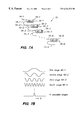
- the optical path length difference can also be changed by using fiber portions having only section(s) with different refractive indexes, as shown in FIG. 6 A.
- a predetermined length (dependent on the desired filter output) of fiber section 61 having a refractive index n 1 can be conventionally fuse-spliced between an undoped or normal fiber portion 18 .
- Various combinations (length and refractive index) of fiber sections in one or both fiber portions 18 and 19 can be used to vary the optical path length and thus the filter output.
- optical path length examples include making one fiber portion 18 or 19 refractive index-sensitive to UV radiation, e.g., by using hydrogen-loaded or Ge-doped fiber, as shown in FIG. 6B (with fiber portion 18 shown), or by making one fiber portion more refractive index-sensitive to UV radiation than the other fiber portion, e.g., by doping at different levels. Fiber portions 18 and 19 are then exposed to UV radiation, for example, at a wavelength range between 150 and 300 nm. Because the refractive index of only one fiber portion changes from the UV radiation or the refractive indexes of the two fiber portions change in different proportions to the UV radiation, an optical path length difference can be created.
- FIG. 6C shows a general relationship between the change of refractive index as a function of UV exposure time for various UV intensities. Note that, in general, the longer the UV intensity and/or exposure time, the more the refractive index changes.
- the phase shift is due to one signal traveling further than the other signal.
- a desired filter output can be obtained by precisely cleaving the ends of fiber portions 18 and 19 to achieve the necessary path length difference. If the refractive indexes of the fiber portions differ, the phase shift is due to the two signals traveling at different phase velocities through the fibers. In this case, precisely monitoring the output while changing the refractive index(es) until the desired filter output appears allows the necessary path length difference to be achieved.
- phase shift is due to contributions from both effects, which may increase or decrease the phase shift depending on whether the length difference in one fiber compensates for or contributes to the phase shift due to the refractive index difference between the two fibers, and vice versa.
- cleaving the fiber and changing the refractive index while monitoring the output can be used in conjunction to obtain the desired filter output.
- a plurality of MWFs 40 of FIG. 4 can be cascaded to form a bandpass filter 70 , as shown in FIG. 7A.
- a first MWF 40 - 1 with optical path length difference ⁇ L between fibers 18 - 1 and 19 - 1 has an output port 15 - 1 coupled to an input port 14 - 2 of a second MWF 40 - 2 with optical path length difference 2 ⁇ L between fibers 18 - 2 and 19 - 2 .
- the output port 15 - 2 of second MWF 40 - 2 is coupled to an input port 14 - 3 of a third MWF 40 - 3 with optical path length difference 3 ⁇ L between fibers 18 - 3 and 19 - 3 .
- MWFs are cascaded in similar manner to a last MWF 40 -N with optical path length difference 2 N ⁇ 1 ⁇ L between fibers 18 -N and 19 -N.
- bandpass filter 70 With bandpass filter 70 , light entering input port 14 - 1 of first MWF 40 - 1 exits output port 15 -N of last MWF 40 -N with a wavelength ⁇ . Thus, bandpass filter 70 only passes signals at the desired wavelength.
- FIG. 7B shows the output spectrum at the output ports 15 of the first four MWFs 40 with the same input for each MWF and the power transfer function of the last MWF 40 -N when N MWFs 40 are cascaded. Consequently, by adjusting the interference phase, bandpass filter 70 can be used to filter a desired wavelength.
- FIG. 7C shows a more detailed spectrum of the output of bandpass filter 70 on a dB scale.
- MWF 40 of FIG. 4 can also be used as part of a multi-window wavelength division multiplexer (MWDM) 80 , as shown in FIG. 8 .
- MWDM 80 utilizes the optical path difference of two signals arriving at coupling region 11 , which, due to the phase shift of the signals, causes different constructive and destructive interference at different wavelengths of the signals traveling out of the coupling region along fiber portions 14 and 15 .
- MWDM 80 has a first MWF 40 - 1 and a second MWF 40 - 2 , both having approximately the same optical path length difference.
- a fiber portion 15 - 1 of first MWF 40 - 1 is coupled to the output fiber of a 3-dB coupler 81
- a fiber portion 14 - 2 of second MWF 40 - 2 is coupled to the other output fiber of 3-dB coupler 81 .
- fiber portions 18 - 1 and 19 - 1 of MWF 40 - 1 have the same optical path length difference as fiber portions 18 - 2 and 19 - 2 of MWF 40 - 2
- the output spectrum from fiber portions 14 - 1 and 15 - 2 will exhibit complementary sinusoidal behavior, which consists of alternating peaks and nulls, as shown in FIG. 9 .
- Solid line 91 represents the amplitude as a function of frequency of the output signal from one fiber output (e.g., fiber portion 14 - 1 ), while dashed line 92 represents the amplitude as a function of frequency for the simultaneous output signal from the other fiber output of the MWDM (e.g., fiber portion 15 - 2 ).
- the window spacing of the MWDM which is normally twice the channel spacing, is defined by the wavelength separation between two adjacent transmission peak wavelengths from a channel, as shown, for example, by the separation of peaks 93 and 95 .
- the wavelength separation (or combination) capability of the MWDM depends on the number of windows and the window spacing of the MWDM. The number of windows or channels in a useable bandwidth can be adjusted by changing the path length difference between the two fiber portions 18 and 19 , such as by any of the methods discussed above.
- the output spectrum as a function of ⁇ , is sinusoidal, and by changing the path length difference, the channel separation can be increased or decreased.
- FIG. 10 shows another embodiment of the present invention, in which an MWDM 100 is formed with one MWF 40 and one optical circulator 101 .
- the optical circulator is an optical device that has at least three optical input/output (I/O) ports 102 , 103 , and 104 , where light entering I/O port 102 is allowed to exit I/O port 103 , light entering I/O port 103 is allowed to exit I/O port 104 , and light entering I/O port 104 is allowed to exit I/O port 102 .
- I/O optical input/output
- MWDM 100 is formed by coupling I/O port 103 to one fiber portion 14 or 15 of MWF 40 (FIG. 10 shows coupling to fiber portion 15 ).
- the two outputs of the MWDM are the other fiber portion (e.g., fiber portion 14 ) of MWF 40 and I/O port 104 of circulator 101 and are complementary, as discussed above.
- the use of a circulator decreases insertion loss associated with the 3-dB coupler, as well as eliminates the need for an additional MWF.
- FIG. 11 shows a high isolation MWDM 110 according to one embodiment.
- MWDM 110 includes an MWDM 111 , which can be the MWDM of FIG. 8 or FIG.
- each of the two output branches 112 and 113 coupled to a single MWF 40 with the same channel separation ⁇ as that of MWDM 111 .
- the resulting output signal from each of the two MWFs 40 has lower sidelobe powers than the signals from the MWDM 111 because the signal processed through the two MWFs 40 with approximately the same transmission function as MWDM 111 , which, on a logarithmic scale, essentially doubles the amount of sidelobe suppression. Consequently, cross-talk is reduced between adjacent and neighboring channels of MWDM 110 .
- This structure can be expanded by cascading additional stages of MWDMs and MWFs.
- the size of the high isolation MWDM 110 can be greatly decreased.
- using MWFs 40 of the present invention can reduce the size of the high isolation MWDM by approximately 2 ⁇ 3.
- FIG. 4 The smaller size is due in part to being able to utilize MWF 40 without bending the fiber for the output, as shown in FIG. 4 .
- FIGS. 8, 10 , and 11 which show the fibers bent so that the output of the MWDM is in the same direction as the input is for illustration purposes only. As can be seen, by bending the fibers, the size of the MWDM necessarily increases.
- the MWDMs of FIGS. 8, 10 , and 11 can be combined, either individually or in various combinations, to create a dense wavelength division multiplexer (DWDM) using techniques disclosed in commonly-owned U.S. Pat. No. 5,809,190, incorporated by reference above.
- DWDM dense wavelength division multiplexer
- the number of channels propagating through a single fiber can be increased by cascading MWDMs, as shown in FIG. 12 .
- Each of the two outputs of a first stage MWDM 120 are coupled to an input of two second stage MWDMs 121 .
- the resulting signal exiting from MWDM 120 will have a channel separation of ⁇ if the channel separation of signals from MWDMs 121 is 2 ⁇ .
- the resulting signal can be demultiplexed or separated by reversing the DWDM, i.e., by transmitting the signal from MWDM 120 out through MWDMs 121 .
- MWDMs of the present invention in a plurality of stages, which decreases the channel isolation, and precisely adjusting the optical path lengths (described above) of the MWDMs, the desired interference state can be obtained for DWDM applications requiring narrow channel spacing.
- DWDMs which may couple, for example, 8, 16, or even 32 discrete communication channels onto a single optic fiber, can be obtained.
- DWDMs are much more sensitive to temperature variations, particularly on the refractive index of the fiber, which can shift the wavelength peaks within the useable bandwidth.
- the refractive index may change at a rate of ⁇ 6 ⁇ 10 ⁇ 6 /° C.
- wavelength peaks may change at a rate of ⁇ 0.007 nm/° C. for light at wavelengths around 1550 nm.
- the wavelength will shift be about 0.7 nm.
- Such a temperature-induced wavelength shift is significant for DWDM applications due to the small separation between channels. For example, with a 16-channel DWDM, the channel spacing might only be ⁇ 0.8 nm, and thus a potential temperature-induced 0.7 nm wavelength shift can pose significant problems.
- a passive thermal compensation (PTC) technique can be used so that changes in the refractive index in one fiber are offset by changes in the other fiber, resulting in little or no change to the optical path length difference.
- PTC passive thermal compensation
- FIGS. 13A-13C Various PTC techniques can be used, some of which are shown in FIGS. 13A-13C.
- MWF 40 of FIG. 4 is shown with fiber portion 18 having length l 1 and refractive index n, and fiber portion 19 having length l 2 and refractive index n 2 .
- FIG. 13B shows another method of PTC.
- the two fiber portions 18 and 19 of MWF 40 are secured to a composite substrate 130 having two different thermal expansion coefficients.
- substrate 130 expands or contracts at different rates where substrate 130 contacts the fiber portions.
- the different rates of expansion change the tension of the fiber portions in differing proportions.
- the refractive index change caused by temperature changes can be compensated for by changes in the tension of fiber portions 18 and 19 .
- substrate 130 can be comprised of a relatively low thermal expansion material (e.g., invar or quartz) contacting the longer optical path length fiber portion (e.g., fiber portion 18 ) and a relatively high thermal expansion material (e.g., Al, Cu, or glass) contacting the shorter optical path length fiber portion (e.g., fiber portion 19 ) so that the phase shift change of the two fiber portions are approximately equal.
- a relatively low thermal expansion material e.g., invar or quartz
- a relatively high thermal expansion material e.g., Al, Cu, or glass
- FIG. 13C shows yet another PTC method suitable for the MWF of the present invention.
- a substrate 135 is secured to a section, under tension, of one fiber portion 18 or 19 of MWF 40 (fiber portion 19 is shown in FIG. 13 C).
- substrate 135 relieves (negative thermal expansion coefficient) or increases (positive thermal expansion coefficient) tension of the secured section of fiber portion 19 .
- substrate 135 should be of a material having a positive thermal expansion coefficient (e.g., epoxy, glue, or Al)
- substrate 135 should be of a material having a negative thermal expansion coefficient (e.g., carbon fiber).
Abstract
Description


Claims (16)
Priority Applications (1)
| Application Number | Priority Date | Filing Date | Title |
|---|---|---|---|
| US09/327,148 US6324322B1 (en) | 1999-06-07 | 1999-06-07 | Fused-fiber multi-window wavelength filter using unbalanced Michelson Interferometer |
Applications Claiming Priority (1)
| Application Number | Priority Date | Filing Date | Title |
|---|---|---|---|
| US09/327,148 US6324322B1 (en) | 1999-06-07 | 1999-06-07 | Fused-fiber multi-window wavelength filter using unbalanced Michelson Interferometer |
Publications (1)
| Publication Number | Publication Date |
|---|---|
| US6324322B1 true US6324322B1 (en) | 2001-11-27 |
Family
ID=23275355
Family Applications (1)
| Application Number | Title | Priority Date | Filing Date |
|---|---|---|---|
| US09/327,148 Expired - Fee Related US6324322B1 (en) | 1999-06-07 | 1999-06-07 | Fused-fiber multi-window wavelength filter using unbalanced Michelson Interferometer |
Country Status (1)
| Country | Link |
|---|---|
| US (1) | US6324322B1 (en) |
Cited By (9)
| Publication number | Priority date | Publication date | Assignee | Title |
|---|---|---|---|---|
| US6498879B1 (en) * | 1999-03-31 | 2002-12-24 | Wavesplitter Technologies, Inc. | Polarization-independent, environmentally stable optical fiber narrow band multi-window wavelength division multiplexer based on biconical tapered fusion coupler technology |
| US6763685B1 (en) * | 1999-11-17 | 2004-07-20 | Itf Optical Technologies Inc. | Fabrication of multiplexing and demultiplexing single-mode fiber optic couplers |
| US20050058394A1 (en) * | 2003-09-11 | 2005-03-17 | The Boeing Company | High extinction ratio fiber interferometer |
| US20050087673A1 (en) * | 2003-10-23 | 2005-04-28 | Ray Chen | Apparatus and method for an electronically tuned, wavelength-dependent optical detector |
| US20050152647A1 (en) * | 2002-11-14 | 2005-07-14 | Johnny Zhong | Athermal fused coupler package for optical fibers |
| US20060204184A1 (en) * | 2004-03-25 | 2006-09-14 | Agilent Technologies, Inc. | Connection arrangement for optical communication systems |
| US20080304137A1 (en) * | 2007-06-06 | 2008-12-11 | Sumitomo Electric Industries, Ltd. | Light source apparatus |
| US20090162073A1 (en) * | 2007-12-20 | 2009-06-25 | Fujitsu Limited | Optical module |
| WO2016018508A3 (en) * | 2014-06-03 | 2016-08-04 | Nikon Metrology Nv | Thermally compensated fiber interferomoeter assembly |
Citations (5)
| Publication number | Priority date | Publication date | Assignee | Title |
|---|---|---|---|---|
| US4831631A (en) * | 1986-09-29 | 1989-05-16 | Siemens Aktiengesellschaft | Laser transmitter comprising a semiconductor laser and an external resonator |
| US5450511A (en) * | 1992-04-29 | 1995-09-12 | At&T Corp. | Efficient reflective multiplexer arrangement |
| US5805751A (en) * | 1995-08-29 | 1998-09-08 | Arroyo Optics, Inc. | Wavelength selective optical couplers |
| US5915051A (en) * | 1997-01-21 | 1999-06-22 | Massascusetts Institute Of Technology | Wavelength-selective optical add/drop switch |
| US5995530A (en) * | 1994-06-17 | 1999-11-30 | Alcatel N.V. | Interferometric semiconductor laser with low-loss coupling of light therefrom and an arrangement with such a laser |
-
1999
- 1999-06-07 US US09/327,148 patent/US6324322B1/en not_active Expired - Fee Related
Patent Citations (5)
| Publication number | Priority date | Publication date | Assignee | Title |
|---|---|---|---|---|
| US4831631A (en) * | 1986-09-29 | 1989-05-16 | Siemens Aktiengesellschaft | Laser transmitter comprising a semiconductor laser and an external resonator |
| US5450511A (en) * | 1992-04-29 | 1995-09-12 | At&T Corp. | Efficient reflective multiplexer arrangement |
| US5995530A (en) * | 1994-06-17 | 1999-11-30 | Alcatel N.V. | Interferometric semiconductor laser with low-loss coupling of light therefrom and an arrangement with such a laser |
| US5805751A (en) * | 1995-08-29 | 1998-09-08 | Arroyo Optics, Inc. | Wavelength selective optical couplers |
| US5915051A (en) * | 1997-01-21 | 1999-06-22 | Massascusetts Institute Of Technology | Wavelength-selective optical add/drop switch |
Cited By (13)
| Publication number | Priority date | Publication date | Assignee | Title |
|---|---|---|---|---|
| US6498879B1 (en) * | 1999-03-31 | 2002-12-24 | Wavesplitter Technologies, Inc. | Polarization-independent, environmentally stable optical fiber narrow band multi-window wavelength division multiplexer based on biconical tapered fusion coupler technology |
| US6763685B1 (en) * | 1999-11-17 | 2004-07-20 | Itf Optical Technologies Inc. | Fabrication of multiplexing and demultiplexing single-mode fiber optic couplers |
| US7065267B2 (en) * | 2002-11-14 | 2006-06-20 | Finisar Corporation | Athermal fused coupler package for optical fibers |
| US20050152647A1 (en) * | 2002-11-14 | 2005-07-14 | Johnny Zhong | Athermal fused coupler package for optical fibers |
| US20050058394A1 (en) * | 2003-09-11 | 2005-03-17 | The Boeing Company | High extinction ratio fiber interferometer |
| US7006725B2 (en) * | 2003-09-11 | 2006-02-28 | The Boeing Company | High extinction ratio fiber interferometer |
| US20050087673A1 (en) * | 2003-10-23 | 2005-04-28 | Ray Chen | Apparatus and method for an electronically tuned, wavelength-dependent optical detector |
| US20060204184A1 (en) * | 2004-03-25 | 2006-09-14 | Agilent Technologies, Inc. | Connection arrangement for optical communication systems |
| US20080304137A1 (en) * | 2007-06-06 | 2008-12-11 | Sumitomo Electric Industries, Ltd. | Light source apparatus |
| US8081376B2 (en) * | 2007-06-06 | 2011-12-20 | Sumitomo Electric Industries, Ltd. | Multi-stage fiber amplifier to suppress Raman scattered light |
| US20090162073A1 (en) * | 2007-12-20 | 2009-06-25 | Fujitsu Limited | Optical module |
| WO2016018508A3 (en) * | 2014-06-03 | 2016-08-04 | Nikon Metrology Nv | Thermally compensated fiber interferomoeter assembly |
| US10989879B2 (en) * | 2014-06-03 | 2021-04-27 | Nikon Metrology Nv | Thermally compensated fiber interferometer assembly |
Similar Documents
| Publication | Publication Date | Title |
|---|---|---|
| US6031948A (en) | Fused-fiber multi-window wavelength division multiplexer using an unbalanced Mach-Zehnder interferometer and method of making same | |
| EP1226461B1 (en) | Phasar with flattened pass-band | |
| US6275322B1 (en) | Michelson phase shifter interleaver/deinterleavers | |
| US6160932A (en) | Expandable wavelength division multiplexer based on interferometric devices | |
| US6363202B1 (en) | Management and control of the power levels of wavelength multiplexed optical signals | |
| US6256433B1 (en) | Expandable interleaving optical add/drop filter module | |
| US20020176659A1 (en) | Dynamically tunable resonator for use in a chromatic dispersion compensator | |
| US6141130A (en) | Spectral equalizer for multiplexed channels | |
| WO2002071118A1 (en) | Dispersion-compensated optical wavelength router | |
| US6584249B1 (en) | Miniature optical dispersion compensator with low insertion loss | |
| US20020126291A1 (en) | Spectrum division multiplexing for high channel count optical networks | |
| US6621632B2 (en) | Optical interferometer for demultiplexing an optical signal | |
| US6324322B1 (en) | Fused-fiber multi-window wavelength filter using unbalanced Michelson Interferometer | |
| US6215924B1 (en) | Optical coupler device for dense wavelength division multiplexing | |
| US6567587B2 (en) | Dispersion compensator and dispersion-compensating module employing the same | |
| US6871022B2 (en) | Cascaded optical multiplexer | |
| US6263128B1 (en) | Fiber unbalanced Mach-Zehnder interferometers with flat-top spectral response for application in wavelength division multiplexers | |
| US6907199B2 (en) | Method for polarization mode dispersion compensation | |
| US7263257B2 (en) | Gires-Tournois etalons and dispersion compensation | |
| JP2003533728A (en) | Chromatic dispersion compensator | |
| US20050249458A1 (en) | Wavelength selection device | |
| US20020176658A1 (en) | Re-configurable wavelength and dispersion selective device | |
| Nyman et al. | Technology trends in dense WDM demultiplexers | |
| US6678441B1 (en) | Multireflector fiber optic filter apparatus and method | |
| JP2001053680A (en) | Dispersion compensator |
Legal Events
| Date | Code | Title | Description |
|---|---|---|---|
| AS | Assignment |
Owner name: WAVE SPLITTER TECHNOLOGIES, INC., CALIFORNIA Free format text: ASSIGNMENT OF ASSIGNORS INTEREST;ASSIGNORS:LUO, HUALI;HUANG, CHI-HUNG;CHON, JOSEPH C.;REEL/FRAME:010021/0129 Effective date: 19990604 |
|
| REMI | Maintenance fee reminder mailed | ||
| AS | Assignment |
Owner name: SILICON VALLEY BANK, CALIFORNIA Free format text: SECURITY AGREEMENT;ASSIGNOR:WAVESPLITTER TECHNOLOGIES, INC.;REEL/FRAME:016536/0640 Effective date: 20050705 |
|
| LAPS | Lapse for failure to pay maintenance fees | ||
| STCH | Information on status: patent discontinuation |
Free format text: PATENT EXPIRED DUE TO NONPAYMENT OF MAINTENANCE FEES UNDER 37 CFR 1.362 |
|
| FP | Lapsed due to failure to pay maintenance fee |
Effective date: 20051127 |
|
| AS | Assignment |
Owner name: WAVESPLITTER TECHNOLOGIES INC., CALIFORNIA Free format text: RELEASE;ASSIGNOR:SILICON VALLEY BANK;REEL/FRAME:021838/0944 Effective date: 20081114 |