US6317586B1 - Method and base station for data transmission in a wireless communications system - Google Patents

Method and base station for data transmission in a wireless communications system Download PDF

Info

Publication number
US6317586B1
US6317586B1 US09/239,421 US23942199A US6317586B1 US 6317586 B1 US6317586 B1 US 6317586B1 US 23942199 A US23942199 A US 23942199A US 6317586 B1 US6317586 B1 US 6317586B1
Authority
US
United States
Prior art keywords
link
signals
accordance
max
space covariance
Prior art date
Legal status (The legal status is an assumption and is not a legal conclusion. Google has not performed a legal analysis and makes no representation as to the accuracy of the status listed.)
Expired - Fee Related
Application number
US09/239,421
Inventor
Martin Haardt
Current Assignee (The listed assignees may be inaccurate. Google has not performed a legal analysis and makes no representation or warranty as to the accuracy of the list.)
Nokia Solutions and Networks GmbH and Co KG
Original Assignee
Siemens AG
Priority date (The priority date is an assumption and is not a legal conclusion. Google has not performed a legal analysis and makes no representation as to the accuracy of the date listed.)
Filing date
Publication date
Application filed by Siemens AG filed Critical Siemens AG
Assigned to SIEMENS AKTIENGESELLSCHAFT reassignment SIEMENS AKTIENGESELLSCHAFT ASSIGNMENT OF ASSIGNORS INTEREST (SEE DOCUMENT FOR DETAILS). Assignors: HAARDT, MARTIN
Application granted granted Critical
Publication of US6317586B1 publication Critical patent/US6317586B1/en
Assigned to NOKIA SIEMENS NETWORKS GMBH & CO. & KG reassignment NOKIA SIEMENS NETWORKS GMBH & CO. & KG ASSIGNMENT OF ASSIGNORS INTEREST (SEE DOCUMENT FOR DETAILS). Assignors: SIEMENS AKTIENGESELLSCHAFT
Anticipated expiration legal-status Critical
Expired - Fee Related legal-status Critical Current

Links

Images

Classifications

    • HELECTRICITY
    • H04ELECTRIC COMMUNICATION TECHNIQUE
    • H04WWIRELESS COMMUNICATION NETWORKS
    • H04W16/00Network planning, e.g. coverage or traffic planning tools; Network deployment, e.g. resource partitioning or cells structures
    • H04W16/24Cell structures
    • H04W16/28Cell structures using beam steering
    • HELECTRICITY
    • H04ELECTRIC COMMUNICATION TECHNIQUE
    • H04BTRANSMISSION
    • H04B7/00Radio transmission systems, i.e. using radiation field
    • H04B7/02Diversity systems; Multi-antenna system, i.e. transmission or reception using multiple antennas
    • H04B7/04Diversity systems; Multi-antenna system, i.e. transmission or reception using multiple antennas using two or more spaced independent antennas
    • H04B7/06Diversity systems; Multi-antenna system, i.e. transmission or reception using multiple antennas using two or more spaced independent antennas at the transmitting station
    • H04B7/0613Diversity systems; Multi-antenna system, i.e. transmission or reception using multiple antennas using two or more spaced independent antennas at the transmitting station using simultaneous transmission
    • H04B7/0615Diversity systems; Multi-antenna system, i.e. transmission or reception using multiple antennas using two or more spaced independent antennas at the transmitting station using simultaneous transmission of weighted versions of same signal
    • H04B7/0617Diversity systems; Multi-antenna system, i.e. transmission or reception using multiple antennas using two or more spaced independent antennas at the transmitting station using simultaneous transmission of weighted versions of same signal for beam forming

Definitions

  • messages for example voice, video information or other data
  • the electromagnetic waves are thereby transmitted at carrier frequencies which are in the frequency band laid out for the respective system.
  • the carrier frequencies are in the region of 900, 1800 or 1900 MHz.
  • UMTS Universal Mobile Telecommunication System
  • 3rd generation systems frequencies in the frequency band of about 2000 MHz are envisaged.
  • FDMA frequency division multiple access
  • TDMA time division multiplex
  • CDMA code division multiple access
  • the GSM mobile radio system which is currently in existence is a wireless communications system using a TDMA component for subscriber separation (Time Division Multiple Access).
  • Wanted information for the subscriber links is transmitted in time slots on the basis of a frame structure. Transmission takes place in blocks.
  • German patent application DE 195 49 148 discloses a mobile communications system which uses TDMA/CDMA subscriber separation (time division and code division multiple access) and uses a JD method (joint detection) at the receiving end in order to improve the detection of the transmitted wanted information on the basis of knowledge of the spread codes of a plurality of subscribers.
  • Information from a plurality of wanted data links is transmitted simultaneously in one frequency channel (TCH traffic channel), and these links can be distinguished by their spread code.
  • Beam forming in the downlink direction is known from Schmalenberger and Blanz, “A Comparison Of Two Different Algorithms For Multi Antenna C/I Balancing,” Proc. 2nd European Personal Mobile Communications Conference (EPMCC), Bonn, Germany, September 1997, pages 483-90, wherein a direct propagation path (line of sight) is assumed to exist between the radio stations involved, together with iterative calculation of beam forming vectors. Whenever the radio stations involved change, for example a link to or from a mobile station is set up or cleared, the entire calculation must be repeated.
  • R xx and R I are the covariance matrices
  • Transmission signals for the link are then weighted with the beam forming vector, and are supplied to the antenna elements for transmission.
  • the computation complexity is thus drastically reduced. Particularly in scenarios having a large number of subscribers and severely fluctuating channel conditions, beam forming in the downlink direction is considerably more economic according to the invention.
  • a unit matrix is set for the space covariance matrix from a sum of influences from further wireless stations. This simplifies the calculation once again, with the generalized intrinsic value problem thus being reduced to a normal intrinsic value problem.
  • FIG. 2 is a schematic illustration of the frame structure for radio transmission
  • FIG. 4 is a block diagram of the antenna device and of the base station with regard to estimation of the space covariance matrices
  • radio blocks for wanted data transmission comprise sections with data d, in which sections with training sequences tseq 1 to tseqn (which are known at the receiving end) are embedded.
  • the data d are spread in a link-specific manner with a fine structure, a subscriber code c, so that, for example, n links can be separated by this CDMA component at the receiving end.
  • the mobile station MSk contains the assemblies explained for the base station and, in addition, a control panel T.
  • the subscriber can enter inputs on the control panel T, inter alia an input for activating the mobile station MS or for setting up a link Vk to the base station.
  • the control device SE evaluates signals transmitted in the downlink direction and received by the mobile station MSk, defines the reception power and the current signal-to-noise ratio that is present, and initiates signaling to the base station BS using a signaling channel ACCH.
  • FIG. 4 shows the base station BS with the associated antenna elements A 1 to Am of the antenna device AE (antenna array).
  • This antenna device AE is associated with the base station BS and receives signals rx from the transmitting mobile stations MS in the mobile radio network, as well as transmitting signals tx to the receiving mobile stations MS.
  • digital signals are produced from the received signals rx, for example by converting them to baseband followed by analog/digital conversion, and these digital signals are evaluated in the receiving device RX (step 1 in FIG. 6 ).
  • the channel pulse responses h which are defined by the channel estimators KS using, for example, a Gaussian-Markov or maximum-likelihood estimation method based on the training sequences tseq 1 to tseqn (step 2 in FIG. 6) and the received digital data symbols e are supplied to the data estimator DS for joint detection. Furthermore, the control device SE receives the channel impulse responses h and the received digital data symbols e in order to define space covariance matrices R xx , R I for a k th link Vk and for the interference of the other links V 1 to Vn and, if appropriate, of the known interference sources.
  • the value for R xx may in this case be averaged over a number of radio blocks by means of a rectangular or exponential window.
  • a vector can thus be set up for the signal received by the m th antenna element
  • the vectors e JD (m) and e I (m) contain elements—JD—of those channel subscribers who are covered by the joint detection, and elements—I—of subscribers in adjacent cells.
  • step 5 in FIG. 6 This is optionally followed by averaging of the values over a number of radio blocks using a rectangular or exponential window.
  • d I (k) is the number of dominant incidence directions of the interfering signals (estimated from the uplink direction)
  • ⁇ I i (k) is a vector with the 1D or 2D spatial frequencies of the i th propagation path of the interference sources
  • a( ⁇ I i (k) ) is the corresponding control vector (array steering vector) for the antenna device AE
  • P Ii is the complex amplitude (estimated from the uplink direction).
  • the method according to the invention can also be applied to DS (direct sequence) CDMA transmission systems.
  • DS direct sequence
  • the channel impulse responses in the uplink direction are evaluated in this case, or 2D rake receivers with MVDR processing (minimum variance distortionless response) are used.

Abstract

Space covariance matrices are first defined for a kth link from the base station to a wireless station and for a sum of further radio stations, that is to say, in the latter case, the interference for the kth link. In a second step, a beam forming vector w(k) is calculated for the link such that the signal-to-noise ratio in the receiver is maximized. A general intrinsic value problem is thereby solved without iterations. Transmission signals are then weighted with the beam forming vector for the link, and are supplied to the antenna elements for transmission. The method is suitable for TDMA/CDMA and CDMA transmission methods using smart antennas.

Description

BACKGROUND OF THE INVENTION
1. Field of the Invention
The invention lies in the telecommunications field. More specifically, the invention relates to a method and a base station for data transmission in a wireless communications system, wherein a base station has an associated antenna device with a plurality of antenna elements, so that spatial resolution in a beam formation can be carried out.
In wireless (radio) communications systems, messages (for example voice, video information or other data) are transmitted with the aid of electromagnetic waves via a radio interface between a transmitting and a receiving station (base station and mobile, respectively). The electromagnetic waves are thereby transmitted at carrier frequencies which are in the frequency band laid out for the respective system. In the case of GSM (Global System for Mobile Communication), the carrier frequencies are in the region of 900, 1800 or 1900 MHz. For future mobile radio networks using CDMA or TD/CDMA transmission methods via the radio interface, for example the UMTS (Universal Mobile Telecommunication System) or other 3rd generation systems, frequencies in the frequency band of about 2000 MHz are envisaged.
During their propagation in a propagation medium, signals are subject to interference from noise. As a result of diffraction and reflections, signal components flow over different propagation paths and are superimposed in the receiver, where they lead to mutual interference effects. Furthermore, if there is more than one signal source, the signals from these sources are superimposed. Frequency division multiplex (FDMA—frequency division multiple access), time division multiplex (TDMA—time division multiple access) or a method which is known as code division multiplex (CDMA—code division multiple access) are used to distinguish between the signal sources, and thus to evaluate the signals.
The GSM mobile radio system which is currently in existence is a wireless communications system using a TDMA component for subscriber separation (Time Division Multiple Access). Wanted information for the subscriber links is transmitted in time slots on the basis of a frame structure. Transmission takes place in blocks.
German patent application DE 195 49 148 discloses a mobile communications system which uses TDMA/CDMA subscriber separation (time division and code division multiple access) and uses a JD method (joint detection) at the receiving end in order to improve the detection of the transmitted wanted information on the basis of knowledge of the spread codes of a plurality of subscribers. Information from a plurality of wanted data links is transmitted simultaneously in one frequency channel (TCH traffic channel), and these links can be distinguished by their spread code.
German patent application DE 197 12 549 discloses the use of intelligent antennas (smart antennas) in order to increase the transmission capacity in the uplink (mobile to base station) direction. Various methods for space signal separation for the uplink (reverse—mobile to base station) and downlink (forward—base station to mobile) directions are known from Paulraj and Papadias, “Space-Time Processing For Wireless Communications,” IEEE Signal Processing Magazine, November 1997, pages 49-83.
For the downlink direction, that is to say from the base station to the mobile, particular difficulties occur since the beam forming must be carried out before the transmitted signals have been influenced by the radio channel. Beam forming in the downlink direction is known from Schmalenberger and Blanz, “A Comparison Of Two Different Algorithms For Multi Antenna C/I Balancing,” Proc. 2nd European Personal Mobile Communications Conference (EPMCC), Bonn, Germany, September 1997, pages 483-90, wherein a direct propagation path (line of sight) is assumed to exist between the radio stations involved, together with iterative calculation of beam forming vectors. Whenever the radio stations involved change, for example a link to or from a mobile station is set up or cleared, the entire calculation must be repeated.
2. Summary of the Invention
It is accordingly an object of the invention to provide an improved method and an improved base station for data transmission, which overcomes the above-mentioned disadvantages of the heretofore-known devices and methods of this general type and in which the computation complexity for beam forming is considerably reduced.
With the foregoing and other objects in view there is provided, in accordance with the invention, a signal transmission method in a wireless communications system of the type having a base station with an antenna device provided with and a plurality of antenna elements, and having a plurality of wireless stations, which method comprises:
defining space covariance matrices for a kth link from the base station to a wireless station and for a sum of further wireless stations;
defining a beam forming vector w(k) in accordance with the condition w ( k ) R xx ( k ) w ( k ) w ( k ) R I ( k ) w ( k ) max
Figure US06317586-20011113-M00001
having a greatest intrinsic value λmax (k) in accordance with
R xx (k) w (k) =R I (k) w (k)λmax (k)
for the link, where Rxx and RI are the covariance matrices;
weighting transmission signals for the link with the beam forming vector; and
transmitting the transmission signals with the antenna elements.
In other words, the novel method for data transmission is used in a radio communications system with a base station and further radio stations. The further radio stations may be mobile stations, for example in a mobile wireless network, or fixed stations, for example in so-called subscriber access networks for wire-free subscriber access.
In a first step, space covariance matrices are defined for a kth link from the base station to a wireless station and for a sum of signals of further radio stations, that is to say, in the latter case, the sum of the interference for the link k.
In a second step, a beam forming vector w(k) is calculated for the link in such a manner that the relationship w ( k ) R xx ( k ) w ( k ) w ( k ) R I ( k ) w ( k )
Figure US06317586-20011113-M00002
is maximized, wherein the generalized intrinsic vector w(k) is defined for the greatest generalized intrinsic value λmax (k) by using Rxx (k)w(k)=RI (k)w(k)λmax (k).
Transmission signals for the link are then weighted with the beam forming vector, and are supplied to the antenna elements for transmission.
This method is used to maximize the power available for the link k in comparison with the interference power, in which case it is possible to dispense with iterations, since the use of the secondary condition Rxx (k)w(k)=RI (k)w(k)λmax (k) for the calculation leads to the desired result in one step. The computation complexity is thus drastically reduced. Particularly in scenarios having a large number of subscribers and severely fluctuating channel conditions, beam forming in the downlink direction is considerably more economic according to the invention.
In accordance with an added feature of the invention, a transmission power is defined for the transmission signals for the link from the beam forming vector in accordance with Pk=w(k)Hw(k), where H is a complex-conjugate vector and Pk is the transmission power, and raising the transmission power to a predetermined minimum signal-to-noise ratio in the radio station. The transmission power is also raised to a predetermined minimum signal-to-noise ratio in the wireless station. The instantaneous signal-to-noise ratio is measured in the receiving wireless station and is reported to the base station, so that the latter can use an appropriate transmission power setting to guarantee the minimum signal-to-noise ratio.
In accordance with an additional feature of the invention, data are transmitted in an uplink direction and a downlink direction in a given frequency band, and at least one of the space covariance matrices with respect to the link for the downlink direction is defined from measured values from the uplink direction. The correspondence between the transmission and reception frequency which exists using TDD (time division duplex) is thus used to reliably define the space channel parameters. There is thus no need to estimate the incidence directions for TDD systems.
If, on the other hand, data are transmitted in the uplink and downlink directions in mutually different frequency bands, then at least one of the space covariance matrices is defined for the downlink direction from dominant incidence directions for received signals with respect to the link in the uplink direction. Reliable space channel parameters can also be determined and continuously updated for this case.
In accordance with a further feature of the invention, a unit matrix is set for the space covariance matrix from a sum of influences from further wireless stations. This simplifies the calculation once again, with the generalized intrinsic value problem thus being reduced to a normal intrinsic value problem.
In accordance with again an added feature of the invention, the space covariance matrices are defined based on estimated channel pulse responses. In accordance with a further development, the channel pulse responses are derived from training sequences transmitted by the wireless station. This leads to particularly high reliability in the definition of the space covariance matrices. Here, the channel measurements are evaluated in addition to obtaining space statements. The channel impulse responses are advantageously defined from training sequences which are transmitted by the radio station. The transmitted training sequences for one or more links are known in the receiving station, so that particularly reliable estimated values can be determined.
In accordance with again another feature of the invention, the method further comprises, in the base station or a wireless station, jointly detecting a plurality of signals differing by virtue of a CDMA code, and eliminating interference from signals not associated with the respective link. Joint detection of a plurality of signals which differ by virtue of a CDMA code, and for interference from signals which are not associated with the link to be eliminated, is particularly advantageous. The requirements for the signal-to-noise ratio are thus reduced, and the transmission power levels required for adequate transmission quality may be reduced.
In accordance with again an additional feature of the invention, the space covariance matrix is set up for a sum of the influences of further wireless stations from received signals of signals not associated with the respective link and/or by joint detection of signals not being considered in the wireless station, in accordance with E I = [ e I ( 1 ) T e I ( 2 ) T e I ( M ) T ] C M × W and R I ( k ) = 1 W E I E I H
Figure US06317586-20011113-M00003
where M is a number of antenna elements in the antenna device and RI is the space covariance matrix.
With the above and other objects in view there is also provided, in accordance with the invention, a base station for data transmission in a wireless communications system with a plurality of wireless stations, comprising:
at least one transmitting device producing transmission signals;
an antenna device with a plurality of antenna elements connected to said transmitting device for transmitting transmission signals;
a control device connected to said transmitting device and a memory device connected to said control device, said control device being programmed:
to define space covariance matrices for a kth link from the base station to a wireless station and for a number of further radio stations, and to store the space covariance matrices in said memory device;
to define, for the respective link, a beam forming vector in accordance with the condition w ( k ) R xx ( k ) w ( k ) w ( k ) R I ( k ) w ( k ) max
Figure US06317586-20011113-M00004
having a greatest intrinsic value λmax (k) in accordance with
R xx (k) w (k) =R I (k) w (k)λmax (k)
and to store the beam forming vector in said memory device; and
to control a weighting of the transmission signals for the respective link with the beam forming vector.
Other features which are considered as characteristic for the invention are set forth in the appended claims.
Although the invention is illustrated and described herein as embodied in a method and base station for data transmission in a radio communications system, it is nevertheless not intended to be limited to the details shown, since various modifications and structural changes may be made therein without departing from the spirit of the invention and within the scope and range of equivalents of the claims.
The construction and method of operation of the invention, however, together with additional objects and advantages thereof will be best understood from the following description of specific embodiments when read in connection with the accompanying drawings.
BRIEF DESCRIPTION OF THE DRAWINGS
FIG. 1 is a diagrammatic block diagram of a mobile wireless network;
FIG. 2 is a schematic illustration of the frame structure for radio transmission;
FIG. 3 is a block diagram showing the base station and mobile station;
FIG. 4 is a block diagram of the antenna device and of the base station with regard to estimation of the space covariance matrices;
FIG. 5 shows a block diagram of a beam forming network; and
FIG. 6 shows a flowchart illustrating a beam forming process.
DESCRIPTION OF THE PREFERRED EMBODIMENTS
Referring now to the figures of the drawing in detail and first, particularly, to FIG. 1 thereof, there is seen a wireless communications system corresponding to GSM mobile radio network. The network comprises a large number of mobile switching centers MSC, which are networked with one another and produce access to a fixed network PSTN. Furthermore, these mobile switching centers MSC are each linked to at least one base station controller BSC. Each base station controller BSC in turn allows a link to be set up to at least one base station BS. Such a base station BS can set up an information link to mobile stations MS via a radio interface.
By way of example, FIG. 1 shows links V1, V2, Vk for transmitting wanted information and signaling information between mobile stations MS1, MS2, MSk, . . . MSn and a base station BS. An operation and maintenance center OMC provides the control and maintenance functions for the mobile radio network, or for parts of it. The functionality of this structure can be transferred to other radio communications systems in which the invention may be used, in particular for subscriber access networks using wireless subscriber connection.
The frame structure for radio transmission is shown in FIG. 2. A broadband frequency range, for example with a bandwidth of B=1.2 MHz, is split into a plurality of timeslots ts, for example 8 timeslots ts1 to ts8, in accordance with a TDMA component. Each timeslot ts within the frequency range B forms a frequency channel FK. Information from a plurality of links is transmitted in radio blocks within the frequency channels TCH, which are provided solely for wanted data transmission.
These radio blocks for wanted data transmission comprise sections with data d, in which sections with training sequences tseq1 to tseqn (which are known at the receiving end) are embedded. The data d are spread in a link-specific manner with a fine structure, a subscriber code c, so that, for example, n links can be separated by this CDMA component at the receiving end.
The spreading of individual symbols of data d results in Q chips of duration Tchip being transmitted within the symbol duration Tsys. The Q chips in this case form the link-specific subscriber code c. Furthermore, a guard time gp is provided within the timeslot ts, in order to compensate for different signal propagation times of the links.
Within a broadband frequency range B, the successive timeslots ts are broken down in accordance with a frame structure. Thus, eight timeslots ts are combined to form a frame, with, for example, a timeslot ts4 in the frame forming a frequency channel for signaling FK or a frequency channel TCH for wanted data transmission, in which case the latter is used repeatedly by a group of links.
FIG. 3 shows radio transmission in the downlink direction from the base station BS to mobile stations MS1 to MSn in a frequency channel TCH for data transmission. The mobile stations MS1 to MSn first of all define one or more frequency ranges B with a sufficiently high or maximum reception power. These are the frequency ranges B for the closest base station BS in whose cell the mobile station MS is currently located. This is how the base station MS and the mobile station MSk are associated.
The base station BS contains a transmitting/receiving device TX/RX which provides digital/analog conversion for the transmission signals to be transmitted, converts them from baseband to the frequency range B for transmission, and modulates and amplifies the transmission signals. A signal production device SA has previously combined the transmission signals into radio blocks, and allocated them to the corresponding frequency channel TCH. A signal processing device DSP evaluates signals received via the transmitting/receiving device TX/RX, and carries out channel estimation.
For signal processing, the received signals are converted into symbols using a discrete range of values, for example digitizers. A signal processing device DSP which, as a digital signal processor, contains a JD processor for detecting the wanted information and the signaling information using the JD-CDMA method (joint detection), also evaluates the data parts d. The interaction of the components is controlled by a control device SE. The data required for space subscriber separation by means of the associated antenna device AE are stored in a memory device SP.
In appropriately adapted form, the mobile station MSk contains the assemblies explained for the base station and, in addition, a control panel T. The subscriber can enter inputs on the control panel T, inter alia an input for activating the mobile station MS or for setting up a link Vk to the base station. The control device SE evaluates signals transmitted in the downlink direction and received by the mobile station MSk, defines the reception power and the current signal-to-noise ratio that is present, and initiates signaling to the base station BS using a signaling channel ACCH.
FIG. 4 shows the base station BS with the associated antenna elements A1 to Am of the antenna device AE (antenna array). This antenna device AE is associated with the base station BS and receives signals rx from the transmitting mobile stations MS in the mobile radio network, as well as transmitting signals tx to the receiving mobile stations MS.
The antenna elements A1 to Am form an antenna device AE which is designed as an intelligent antenna device, that is to say a plurality of antenna elements A1 to Am in this intelligent antenna device AE receive signals rx and transmit signals tx at the same time. The signals can be combined with one another in such a manner that the transmission quality is better than that with systems using one receiving antenna, and space resolution to increase the capacity is feasible.
During reception, digital signals are produced from the received signals rx, for example by converting them to baseband followed by analog/digital conversion, and these digital signals are evaluated in the receiving device RX (step 1 in FIG. 6).
As part of the signal processing device DSP, the receiving device RX comprises a plurality of channel estimators KS and a data estimator DS, as well as the already mentioned control device SE and memory device SP. In addition, the receiving device RX has a-priori knowledge of the number K of subscribers, their training sequences tseq1, . . . , tseqn (K≦n) and their subscriber code c, and may also have information relating to interference signals.
The channel pulse responses h, which are defined by the channel estimators KS using, for example, a Gaussian-Markov or maximum-likelihood estimation method based on the training sequences tseq1 to tseqn (step 2 in FIG. 6) and the received digital data symbols e are supplied to the data estimator DS for joint detection. Furthermore, the control device SE receives the channel impulse responses h and the received digital data symbols e in order to define space covariance matrices Rxx, RI for a kth link Vk and for the interference of the other links V1 to Vn and, if appropriate, of the known interference sources.
In TDD systems, the received signals can be defined directly, that is to say from H = [ h h ( k , 1 ) T h h ( k , 2 ) T h h ( k , M ) T ] C M × W , 1 k K
Figure US06317586-20011113-M00005
where M is the number of antenna elements, K is the number of active subscribers and H is the matrix of channel impulse responses h of length W. An estimated value for the space covariance matrix Rxx for the link Vk is, for example, in accordance with R xx ( k ) = 1 W · H ( k ) H ( k ) H
Figure US06317586-20011113-M00006
(step 2 in FIG. 6). The value for Rxx may in this case be averaged over a number of radio blocks by means of a rectangular or exponential window.
The training sequences tseq1 to tseqn are likewise used for the space covariance matrix RI for interference resulting from the interference sources and from the signals from the other links which (if JD is used) are not detected by joint detection in the mobile station MSk. In this case, the influences of the signals for the kth link and of the links which may be detected by joint detection in the mobile station MSk should be subtracted (step 4 in FIG. 6).
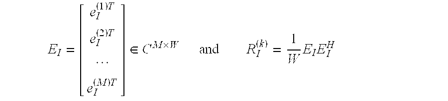
A vector can thus be set up for the signal received by the mth antenna element Am e(m)=[e1 (m) e2 (m) . . . eL (m)]T=eJD (m)+eI (m), 1≦m≦M, where L is the number of samples which are influenced solely by the training sequences, that is to say a number of samples may be ignored owing to interference with the preceding data symbols d. The vectors eJD (m) and eI (m) contain elements—JD—of those channel subscribers who are covered by the joint detection, and elements—I—of subscribers in adjacent cells.
If the training sequence tseqk of the kth subscriber, of length L+W−1 is denoted by si (k), then the vector eJD (m) can be stated as follows: e JD ( m ) = k = 1 K ( [ S W ( k ) S W - 1 ( k ) S W - 2 ( k ) S 1 ( k ) S W + 1 ( k ) S W ( k ) S W - 1 ( k ) S 2 ( k ) S W + L - 1 ( k ) S W + L - 2 ( k ) S W + L - 3 ( k ) S L ( k ) ] h ( k , m ) ) .
Figure US06317586-20011113-M00007
The vector eI (m) contains only elements of the interfering subscribers in the same frequency channel in adjacent cells, so that it can be said that:
e I (m) =e (m) −e JD (m),
for each antenna element m, 1≦m≦M.
A vector E 1 = [ e I ( 1 ) T e I ( 2 ) T e I ( M ) T ] C M × W
Figure US06317586-20011113-M00008
can thus be stated and the space covariance matrix RI can be stated as R I ( k ) = 1 W · E I E I H
Figure US06317586-20011113-M00009
(step 5 in FIG. 6). This is optionally followed by averaging of the values over a number of radio blocks using a rectangular or exponential window.
In FDD systems (frequency division duplex), the space covariance matrices Rxx, RI for the downlink direction are estimated from specific dominant incidence directions and the corresponding amplitudes in the uplink direction.
For example, the matrix Rxx results from: R xx ( k ) = i = 1 d ( k ) p i ( k ) · a ( μ i ( k ) ) a H ( μ i ( k ) )
Figure US06317586-20011113-M00010
where dI(k) is the number of dominant incidence directions for the kth subscriber (estimated from the uplink direction), μi (k) is a vector with the 1D or 2D spatial frequencies of the ith propagation path, a(μi (k)) is the corresponding control vector (array steering vector) for the antenna device AE, and pIi is the complex amplitude (estimated from the uplink direction).
The matrix RI thus becomes: R I ( k ) = i = 1 d I ( k ) p I i ( k ) · a ( μ I i ( k ) ) a H ( μ I i ( k ) )
Figure US06317586-20011113-M00011
where dI(k) is the number of dominant incidence directions of the interfering signals (estimated from the uplink direction), μI i (k) is a vector with the 1D or 2D spatial frequencies of the ith propagation path of the interference sources, a(μI i (k)) is the corresponding control vector (array steering vector) for the antenna device AE, and PIi is the complex amplitude (estimated from the uplink direction).
This procedure corresponds to steps 2 and 3 as well as 4 and 5, respectively, in FIG. 6.
As an alternative to the described TDMA/CDMA radio interface, the method according to the invention can also be applied to DS (direct sequence) CDMA transmission systems. In order to estimate the space covariance matrices Rxx, RI, the channel impulse responses in the uplink direction are evaluated in this case, or 2D rake receivers with MVDR processing (minimum variance distortionless response) are used.
In a further step (step 6 in FIG. 6), a beam forming vector w(k) is calculated for the kth link in accordance with the equation: w ( k ) R xx ( k ) w ( k ) w ( k ) R I ( k ) w ( k ) max
Figure US06317586-20011113-M00012
where w(k) is the generalized intrinsic vector relating to the largest generalized intrinsic value λ(k) max in accordance with
R xx (k) w (k) =R I (k) w (k)λmax (k)
This corresponds to a general intrinsic value problem, which can also be simplified by using a standard matrix I for RI. The calculation is carried out without iterations.
The transmission power for the transmission signals tx for the link k is defined from the beam forming vector w(k) in accordance with the relationship Pk=w(k)Hw(k), where H denotes a complex-conjugate vector.
In step 7 in FIG. 6, a check is carried out to determine whether the signal-to-noise ratio at the mobile station MSk is adequate. If this is not the case, then the transmission power Pk is also raised to a predetermined minimum signal-to-noise ratio in the radio station. The instantaneous signal-to-noise ratio is measured in the receiving radio station, and is reported to the base station.
Transmission signals for the link are then weighted with the beam forming vector w(k) and are supplied to the antenna elements for transmission (step 9 in FIG. 6).
A network for beam forming is shown by way of example in FIG. 5 for two links with transmission signals tx1 and tx2. The links are allocated beam forming vectors w1 and w2, which are multiplied by the transmission signals tx1 and tx2, with the weighted transmission signals tx1 and tx2 being superimposed for each individual antenna element, are converted into radio-frequency transmission signals in an HF section HF-T, and are then transmitted via m individual antenna elements. The transmission signals tx1 and tx2 are transmitted in the same frequency channel (at the same transmission frequency, possibly in the same timeslot and/or with the same code), and are only spatially separated.
The use of different beam forming vectors w1, w2 for the various links results in the antenna device AE having a transmission characteristic which ensures undisturbed reception of the transmission signals tx1, tx2 at the corresponding positions of the mobile stations MS1, MSk.

Claims (13)

I claim:
1. A signal transmission method in a wireless communications system of the type having a base station with an antenna device provided with and a plurality of antenna elements, and having a plurality of wireless stations, which method comprises:
defining space covariance matrices for a kth link from the base station to a first wireless station, and for a sum of further wireless stations by setting up the space covariance matrix for a sum of the influences of further wireless stations from received signals of signals not associated with the respective link and by joint detection of signals not being considered in the first wireless station, in accordance with E I = [ e I ( 1 ) T e I ( 2 ) T e I ( M ) T ] C M × W and R I ( k ) = 1 W E I E I H
Figure US06317586-20011113-M00013
where M is a number of antenna elements in the antenna device and RI is the space covariance matrix;
defining a beam forming vector w(k) in accordance with the condition w ( k ) R xx ( k ) w ( k ) w ( k ) R I ( k ) w ( k ) max
Figure US06317586-20011113-M00014
 having a greatest intrinsic value λmax (k) in accordance with
R xx (k) w (k) =R I (k) w (k)λmax (k)
 for the link, where Rxx and RI are the covariance matrices;
weighting transmission signals for the link with the beam forming vector; and
transmitting the transmission signals with the antenna elements.
2. The method according to claim 1, which comprises defining a transmission power for the transmission signals for the link from the beam forming vector in accordance with Pk=w(k)Hw(k), where H is a complex-conjugate vector and Pk is the transmission power, and raising the transmission power to a predetermined minimum signal-to-noise ratio in the radio station.
3. The method according to claim 1, which comprises transmitting data in an uplink direction and a downlink direction in a given frequency band, and defining at least one of the space covariance matrices with respect to the link for the downlink direction from measured values from the uplink direction.
4. The method according to claim 1, which comprises transmitting data in an uplink direction and a downlink direction in mutually different frequency bands, and defining at least one of the space covariance matrices for the downlink direction from dominant incidence directions for received signals with respect to the link in the uplink direction.
5. The method according to claim 1, which comprises setting a unit matrix for the space covariance matrix from a sum of influences from further radio stations.
6. The method according to claim 1, wherein the step of defining the space covariance matrices comprises defining the covariance matrices based on estimated channel pulse responses.
7. The method according to claim 6, which further comprises defining the channel pulse responses from training sequences transmitted by the wireless station.
8. The method according to claim 1, which comprises, in one of the base station and a wireless station, jointly detecting a plurality of signals differing by virtue of a CDMA code, and eliminating interference from signals not associated with the respective link.
9. A base station for data transmission in a wireless communications system with a plurality of wireless stations, comprising:
at least one transmitting device producing transmission signals;
an antenna device with a plurality of antenna elements connected to said transmitting device for transmitting transmission signals;
a control device connected to said transmitting device and a memory device connected to said control device, said control device being programmed:
to define space covariance matrices for a kth link from the base station to a first wireless station and for a number of further radio stations, and to store the space covariance matrices in said memory device;
to set up the space covariance matrix for a sum of the influences of further wireless stations from received signals of signals not associated with the respective link and by joint detection of signals not being considered in the first wireless station, in accordance with E I = [ e I ( 1 ) T e I ( 2 ) T e I ( M ) T ] C M × W and R I ( k ) = 1 W E I E I H
Figure US06317586-20011113-M00015
where M is a number of antenna elements in the antenna device and RI is the space covariance matrix;
to define, for the respective link, a beam forming vector in accordance with the condition w ( k ) R xx ( k ) w ( k ) w ( k ) R I ( k ) w ( k ) max
Figure US06317586-20011113-M00016
 having a greatest intrinsic value λmax (k) in accordance with
R xx (k) w (k) =R I (k) w (k)λmax (k)
 and to store the beam forming vector in said memory device; and
to control a weighting of the transmission signals for the respective link with the beam forming vector.
10. A signal transmission method in a wireless communications system of the type having a base station with an antenna device provided with and a plurality of antenna elements, and having a plurality of wireless stations, which method comprises:
defining space covariance matrices for a kth link from the base station to a first wireless station, and for a sum of further wireless stations by setting up the space covariance matrix for a sum of the influences of further wireless stations from received signals of signals not associated with the respective link in accordance with E I = [ e I ( 1 ) T e I ( 2 ) T e I ( M ) T ] C M × W and R I ( k ) = 1 W E I E I H
Figure US06317586-20011113-M00017
where M is a number of antenna elements in the antenna device and RI is the space covariance matrix;
defining a beam forming vector w(k) in accordance with the condition w ( k ) R xx ( k ) w ( k ) w ( k ) R I ( k ) w ( k ) max
Figure US06317586-20011113-M00018
 having a greatest intrinsic value λmax (k) in accordance with
R xx (k) w (k) =R I (k) w (k)λmax (k)
 for the link, where Rxx and RI are the covariance matrices;
weighting transmission signals for the link with the beam forming vector; and
transmitting the transmission signals with the antenna elements.
11. A signal transmission method in a wireless communications system of the type having a base station with an antenna device provided with and a plurality of antenna elements, and having a plurality of wireless stations, which method comprises:
defining space covariance matrices for a kth link from the base station to a first wireless station, and for a sum of further wireless stations by setting up the space covariance matrix for a sum of the influences of further wireless stations from received signals by joint detection of signals not being considered in the first wireless station, in accordance with E I = [ e I ( 1 ) T e I ( 2 ) T e I ( M ) T ] C M × W and R I ( k ) = 1 W E I E I H
Figure US06317586-20011113-M00019
where M is a number of antenna elements in the antenna device and RI is the space covariance matrix;
defining a beam forming vector w(k) in accordance with the condition w ( k ) R xx ( k ) w ( k ) w ( k ) R I ( k ) w ( k ) max
Figure US06317586-20011113-M00020
 having a greatest intrinsic value λmax (k) in accordance with
R xx (k) w (k) =R I (k) w (k)λmax (k)
 for the link, where Rxx and RI are the covariance matrices;
weighting transmission signals for the link with the beam forming vector; and
transmitting the transmission signals with the antenna elements.
12. A base station for data transmission in a wireless communications system with a plurality of wireless stations, comprising:
at least one transmitting device producing transmission signals;
an antenna device with a plurality of antenna elements connected to said transmitting device for transmitting transmission signals;
a control device connected to said transmitting device and a memory device connected to said control device, said control device being programmed:
to define space covariance matrices for a kth link from the base station to a first wireless station and for a number of further radio stations, and to store the space covariance matrices in said memory device;
to set up the space covariance matrix for a sum of the influences of further wireless stations from received signals of signals not associated with the respective link in accordance with E I = [ e I ( 1 ) T e I ( 2 ) T e I ( M ) T ] C M × W and R I ( k ) = 1 W E I E I H
Figure US06317586-20011113-M00021
where M is a number of antenna elements in the antenna device and RI is the space covariance matrix;
to define, for the respective link, a beam forming vector in accordance with the condition w ( k ) R xx ( k ) w ( k ) w ( k ) R I ( k ) w ( k ) max
Figure US06317586-20011113-M00022
 having a greatest intrinsic value λmax (k) in accordance with
R xx (k) w (k) =R I (k) w (k)λmax (k)
 and to store the beam forming vector in said memory device; and
to control a weighting of the transmission signals for the respective link with the beam forming vector.
13. A base station for data transmission in a wireless communications system with a plurality of wireless stations, comprising:
at least one transmitting device producing transmission signals;
an antenna device with a plurality of antenna elements connected to said transmitting device for transmitting transmission signals;
a control device connected to said transmitting device and a memory device connected to said control device, said control device being programmed:
to define space covariance matrices for a kth link from the base station to a first wireless station and for a number of further radio stations, and to store the space covariance matrices in said memory device;
to set up the space covariance matrix for a sum of the influences of further wireless stations from received signals by joint detection of signals not being considered in the first wireless station, in accordance with E I = [ e I ( 1 ) T e I ( 2 ) T e I ( M ) T ] C M × W and R I ( k ) = 1 W E I E I H
Figure US06317586-20011113-M00023
where M is a number of antenna elements in the antenna device and RI is the space covariance matrix;
to define, for the respective link, a beam forming vector in accordance with the condition w ( k ) R xx ( k ) w ( k ) w ( k ) R I ( k ) w ( k ) max
Figure US06317586-20011113-M00024
 having a greatest intrinsic value λmax (k) in accordance with
R xx (k) w (k) =R I (k) w (k)λmax (k)
 and to store the beam forming vector in said memory device; and
to control a weighting of the transmission signals for the respective link with the beam forming vector.
US09/239,421 1998-01-28 1999-01-28 Method and base station for data transmission in a wireless communications system Expired - Fee Related US6317586B1 (en)

Applications Claiming Priority (2)

Application Number Priority Date Filing Date Title
DE19803188 1998-01-28
DE19803188A DE19803188B4 (en) 1998-01-28 1998-01-28 Method and base station for data transmission in a radio communication system

Publications (1)

Publication Number Publication Date
US6317586B1 true US6317586B1 (en) 2001-11-13

Family

ID=7855890

Family Applications (1)

Application Number Title Priority Date Filing Date
US09/239,421 Expired - Fee Related US6317586B1 (en) 1998-01-28 1999-01-28 Method and base station for data transmission in a wireless communications system

Country Status (3)

Country Link
US (1) US6317586B1 (en)
CN (1) CN1158885C (en)
DE (1) DE19803188B4 (en)

Cited By (17)

* Cited by examiner, † Cited by third party
Publication number Priority date Publication date Assignee Title
US20020168941A1 (en) * 1999-12-17 2002-11-14 Mitsuru Uesugi Apparatus and Method for Interference Suppression Transmission
US6498939B1 (en) * 1999-07-20 2002-12-24 Texas Instruments Incorporated Wireless network
US20030087674A1 (en) * 2000-06-12 2003-05-08 China Academy Of Telecommunications Technology Apparatus and method using smart antenna in FDD wireless communication system
EP1320146A1 (en) * 2001-12-14 2003-06-18 Dyctel Infraestructuras de Telecomunicaciones, S.A. Multistandard multiband intelligent antenna system for cellular communications in multioperator environments
US20030125002A1 (en) * 2002-01-03 2003-07-03 Motorola Inc. Method and apparatus for transmitting a traffic signal using an adaptive antenna array
JP2003534708A (en) * 2000-05-22 2003-11-18 シーメンス アクチエンゲゼルシヤフト Method and system for estimating interference covariance matrix for downlink connection in cellular mobile radio network with adaptive antenna
US20030214917A1 (en) * 2001-09-28 2003-11-20 At&T Corp. Method and apparatus for reducing interference in multiple-input-multiple-output (MIMO) systems
WO2003098837A1 (en) * 2002-05-17 2003-11-27 Samsung Electronics Co., Ltd. Apparatus and method for forming a forward link transmission beam of a smart antenna in a mobile communication system
US6718184B1 (en) * 2000-09-28 2004-04-06 Lucent Technologies Inc. Method and system for adaptive signal processing for an antenna array
US20040082299A1 (en) * 2000-05-25 2004-04-29 Christopher Brunner Method for controlling the formation of a downlink beam
US20040229567A1 (en) * 2001-10-05 2004-11-18 Attila Bilgic Method and device for iterative JD equalization
WO2006030035A1 (en) * 2004-08-10 2006-03-23 Antennea Technologies, S.L. Plug-in adaptive antenna system and operating method thereof
US7065373B2 (en) 2002-10-18 2006-06-20 Itt Manufacturing Enterprises, Inc. Method of steering smart antennas
US7181244B2 (en) * 2000-11-16 2007-02-20 Qualcomm, Incorporated Method and apparatus for using position location to direct narrow beam antennas
EP2001142A2 (en) * 2006-01-18 2008-12-10 Shanghai Ultimate Power Communications Technology Co., Ltd. Downlink beam forming method and device of time division code division multiple access system
US20100195747A1 (en) * 2009-02-05 2010-08-05 Qualcomm Incorporated Method and apparatus for performing joint detection with a common midamble
RU2471271C2 (en) * 2011-03-11 2012-12-27 Петр Николаевич Башлы Method of optimising wideband antenna arrays

Families Citing this family (16)

* Cited by examiner, † Cited by third party
Publication number Priority date Publication date Assignee Title
DE19950577C2 (en) * 1999-10-20 2002-08-22 Siemens Ag Complex CORDIC procedure for signal processing tasks as well as radio communication system for the implementation of the procedure
DE19951524C1 (en) * 1999-10-26 2001-08-23 Siemens Ag Beam shaping method in a radio communication system
DE10026076C2 (en) * 2000-05-25 2002-11-07 Siemens Ag Method and device for evaluating an uplink radio signal
DE10026077B4 (en) * 2000-05-25 2007-03-22 Siemens Ag Beamforming method
DE10025989B4 (en) * 2000-05-25 2005-11-03 Siemens Ag Beamforming method
DE10032426B4 (en) * 2000-07-04 2006-01-12 Siemens Ag Beamforming method
DE10032427A1 (en) * 2000-07-04 2002-01-24 Siemens Ag Method and device for evaluating a radio signal
DE10051133A1 (en) 2000-10-16 2002-05-02 Siemens Ag Beamforming method
DE10051144C2 (en) * 2000-10-16 2002-11-14 Siemens Ag Method for improving channel estimation in a radio communication system
DE10058060A1 (en) 2000-11-23 2002-05-29 Siemens Ag Method and device for transmitting feedback in a radio communication system
US6836673B1 (en) 2000-12-22 2004-12-28 Arraycomm, Inc. Mitigating ghost signal interference in adaptive array systems
US6731705B2 (en) * 2000-12-22 2004-05-04 Arraycomm, Inc. Method and apparatus for mitigating inter-channel interference in adaptive array systems
CN100369493C (en) * 2001-07-14 2008-02-13 中兴通讯股份有限公司 Linear conversion method for receiving and transmitting right values of array antenna
EP1294209A1 (en) * 2001-09-14 2003-03-19 Siemens Aktiengesellschaft A method for determining location specific transmitter signals taking into account source specific quality criteria
DE10232694A1 (en) * 2002-07-18 2004-01-29 Siemens Ag Dynamic adaptation of beam shaping in radio communications system involves base station determining criteria for selecting feedback information depending on reception characteristic changes with time
DE102007023099B4 (en) * 2007-05-16 2012-06-21 Eads Deutschland Gmbh Method for calculating improved steering vectors

Citations (6)

* Cited by examiner, † Cited by third party
Publication number Priority date Publication date Assignee Title
WO1997024892A2 (en) 1995-12-29 1997-07-10 Siemens Aktiengesellschaft Process and arrangement for radio transmission between a base station and a plurality of subscriber stations
US5970060A (en) * 1995-10-06 1999-10-19 Siemens Aktiengesellschaft Method and system for radio transmission of digital signals
US6084967A (en) * 1997-10-29 2000-07-04 Motorola, Inc. Radio telecommunication device and method of authenticating a user with a voice authentication token
US6091361A (en) * 1998-05-12 2000-07-18 Davis; Dennis W. Method and apparatus for joint space-time array signal processing
US6101399A (en) * 1995-02-22 2000-08-08 The Board Of Trustees Of The Leland Stanford Jr. University Adaptive beam forming for transmitter operation in a wireless communication system
US6225948B1 (en) 1998-03-25 2001-05-01 Siemens Aktiengesellschaft Method for direction estimation

Family Cites Families (4)

* Cited by examiner, † Cited by third party
Publication number Priority date Publication date Assignee Title
US5299148A (en) * 1988-10-28 1994-03-29 The Regents Of The University Of California Self-coherence restoring signal extraction and estimation of signal direction of arrival
US5515378A (en) * 1991-12-12 1996-05-07 Arraycomm, Inc. Spatial division multiple access wireless communication systems
US5260968A (en) * 1992-06-23 1993-11-09 The Regents Of The University Of California Method and apparatus for multiplexing communications signals through blind adaptive spatial filtering
DE59802725D1 (en) * 1997-03-25 2002-02-21 Siemens Ag DIRECTION ESTIMATE METHOD

Patent Citations (6)

* Cited by examiner, † Cited by third party
Publication number Priority date Publication date Assignee Title
US6101399A (en) * 1995-02-22 2000-08-08 The Board Of Trustees Of The Leland Stanford Jr. University Adaptive beam forming for transmitter operation in a wireless communication system
US5970060A (en) * 1995-10-06 1999-10-19 Siemens Aktiengesellschaft Method and system for radio transmission of digital signals
WO1997024892A2 (en) 1995-12-29 1997-07-10 Siemens Aktiengesellschaft Process and arrangement for radio transmission between a base station and a plurality of subscriber stations
US6084967A (en) * 1997-10-29 2000-07-04 Motorola, Inc. Radio telecommunication device and method of authenticating a user with a voice authentication token
US6225948B1 (en) 1998-03-25 2001-05-01 Siemens Aktiengesellschaft Method for direction estimation
US6091361A (en) * 1998-05-12 2000-07-18 Davis; Dennis W. Method and apparatus for joint space-time array signal processing

Non-Patent Citations (2)

* Cited by examiner, † Cited by third party
Title
"A Comparison of Two Different Algorithms for Multi Antenna C/I Balancing", Ralph Schmalenberger et al., Research Group for RF Communications, University of Kaiserslautern, pp. 1-7.
"Space-Time Processing for Wireless Communications", Aroguaswami J. Paulraj et al., Ieee Signal Processing Magazine, Nov. 1997, pp. 49-83.

Cited By (29)

* Cited by examiner, † Cited by third party
Publication number Priority date Publication date Assignee Title
US6498939B1 (en) * 1999-07-20 2002-12-24 Texas Instruments Incorporated Wireless network
US20020168941A1 (en) * 1999-12-17 2002-11-14 Mitsuru Uesugi Apparatus and Method for Interference Suppression Transmission
US7133642B2 (en) 1999-12-17 2006-11-07 Matsushita Electric Industrial Co., Ltd. Apparatus and method for interference suppression transmission
JP4705306B2 (en) * 2000-05-22 2011-06-22 ノキア シーメンス ネットワークス ゲゼルシャフト ミット ベシュレンクテル ハフツング ウント コンパニー コマンディトゲゼルシャフト Method and communication system for estimating interference covariance matrix for downlink connection of cellular mobile radio network with adaptive antenna
JP2003534708A (en) * 2000-05-22 2003-11-18 シーメンス アクチエンゲゼルシヤフト Method and system for estimating interference covariance matrix for downlink connection in cellular mobile radio network with adaptive antenna
US7039368B2 (en) * 2000-05-25 2006-05-02 Siemens Aktiengesellschaft Method for controlling the formation of a downlink beam
US20040082299A1 (en) * 2000-05-25 2004-04-29 Christopher Brunner Method for controlling the formation of a downlink beam
US20030087674A1 (en) * 2000-06-12 2003-05-08 China Academy Of Telecommunications Technology Apparatus and method using smart antenna in FDD wireless communication system
US7394799B2 (en) * 2000-06-12 2008-07-01 China Academy Of Telecommunications Technology Apparatus and method using smart antenna in FDD wireless communication system
US6718184B1 (en) * 2000-09-28 2004-04-06 Lucent Technologies Inc. Method and system for adaptive signal processing for an antenna array
US7181244B2 (en) * 2000-11-16 2007-02-20 Qualcomm, Incorporated Method and apparatus for using position location to direct narrow beam antennas
US20030214917A1 (en) * 2001-09-28 2003-11-20 At&T Corp. Method and apparatus for reducing interference in multiple-input-multiple-output (MIMO) systems
US7912014B2 (en) * 2001-09-28 2011-03-22 At&T Intellectual Property Ii, Lp Method and apparatus for reducing interference in multiple-input-multiple-output (MIMO) systems
US20040229567A1 (en) * 2001-10-05 2004-11-18 Attila Bilgic Method and device for iterative JD equalization
EP1320146A1 (en) * 2001-12-14 2003-06-18 Dyctel Infraestructuras de Telecomunicaciones, S.A. Multistandard multiband intelligent antenna system for cellular communications in multioperator environments
ES2192970A1 (en) * 2001-12-14 2003-10-16 Dyctel Infraestructuras De Tel Multistandard multiband intelligent antenna system for cellular communications in multioperator environments
US20030125002A1 (en) * 2002-01-03 2003-07-03 Motorola Inc. Method and apparatus for transmitting a traffic signal using an adaptive antenna array
US6983172B2 (en) * 2002-01-03 2006-01-03 Motorola, Inc. Method and apparatus for transmitting a traffic signal using an adaptive antenna array
WO2003098837A1 (en) * 2002-05-17 2003-11-27 Samsung Electronics Co., Ltd. Apparatus and method for forming a forward link transmission beam of a smart antenna in a mobile communication system
CN100454775C (en) * 2002-05-17 2009-01-21 三星电子株式会社 Apparatus and method for forming a forward link transmission beam of a smart antenna in a mobile communication system
US7065373B2 (en) 2002-10-18 2006-06-20 Itt Manufacturing Enterprises, Inc. Method of steering smart antennas
WO2006030035A1 (en) * 2004-08-10 2006-03-23 Antennea Technologies, S.L. Plug-in adaptive antenna system and operating method thereof
EP2001142A2 (en) * 2006-01-18 2008-12-10 Shanghai Ultimate Power Communications Technology Co., Ltd. Downlink beam forming method and device of time division code division multiple access system
US20110003552A1 (en) * 2006-01-18 2011-01-06 Shanghai Ultimate Power Communications Technology Co., Ltd. Method and apparatus for downlink beam forming in td-cdma system
EP2001142A4 (en) * 2006-01-18 2012-08-22 Shanghai Ultimate Power Comm Downlink beam forming method and device of time division code division multiple access system
US8811904B2 (en) 2006-01-18 2014-08-19 Shanghai Ultimate Power Communications Technology Co., Ltd. Method and apparatus for downlink beam forming in TD-CDMA system
US20100195747A1 (en) * 2009-02-05 2010-08-05 Qualcomm Incorporated Method and apparatus for performing joint detection with a common midamble
US8311154B2 (en) * 2009-02-05 2012-11-13 Qualcomm Incorporated Method and apparatus for performing joint detection with a common midamble
RU2471271C2 (en) * 2011-03-11 2012-12-27 Петр Николаевич Башлы Method of optimising wideband antenna arrays

Also Published As

Publication number Publication date
CN1233923A (en) 1999-11-03
CN1158885C (en) 2004-07-21
DE19803188B4 (en) 2006-04-20
DE19803188A1 (en) 1999-07-29

Similar Documents

Publication Publication Date Title
US6317586B1 (en) Method and base station for data transmission in a wireless communications system
US7369877B2 (en) Multi-channel demodulation with blind digital beamforming
US6415163B1 (en) Method for transmitting pilot channels and a cellular radio system
US7286855B2 (en) Method and apparatus for adaptive transmission beam forming in a wireless communication system
US6606314B1 (en) Method and radio station for data transmission
US7099630B2 (en) Beam forming method
CN100454775C (en) Apparatus and method for forming a forward link transmission beam of a smart antenna in a mobile communication system
JP4319782B2 (en) Method and apparatus for determining the direction of arrival of a signal
EP1386421B1 (en) Radio communication system
US6470194B1 (en) Base station with improved directivity using adaptive antenna array reception
US6470192B1 (en) Method of an apparatus for beam reduction and combining in a radio communications system
US20030128677A1 (en) Method and system for transmitting data, with transmission antenna diversity
US20030144032A1 (en) Beam forming method
EP1371146B1 (en) Interference rejection in a receiver
US7006849B2 (en) Spatial domain matched filtering method and array receiver in wireless communication system
US7660561B2 (en) Method and system for implementing smart antennas and diversity techniques
US6865175B1 (en) Method and configuration for transmitting data over a radio interface in a radio communications system
EP1176737A2 (en) Radio equipment capable of real time change of antenna directivity and doppler frequency estimating circuit used for the radio equipment
US20040038702A1 (en) Radio communication method, base station and mobile station
US6959070B2 (en) Radio base station apparatus and radio communication method
US6956841B1 (en) Receiver and method of receiving a desired signal
US20020137548A1 (en) Base station apparatus and method for wireless communications
US6381260B1 (en) Method and radio station for data transmission
Asakura et al. Cooperative signal reception and down-link beam forming in cellular mobile communications
US20030108028A1 (en) Method and device for evaluation of a radio signal

Legal Events

Date Code Title Description
AS Assignment

Owner name: SIEMENS AKTIENGESELLSCHAFT, GERMANY

Free format text: ASSIGNMENT OF ASSIGNORS INTEREST;ASSIGNOR:HAARDT, MARTIN;REEL/FRAME:012162/0808

Effective date: 19990201

FPAY Fee payment

Year of fee payment: 4

AS Assignment

Owner name: NOKIA SIEMENS NETWORKS GMBH & CO. & KG, GERMANY

Free format text: ASSIGNMENT OF ASSIGNORS INTEREST;ASSIGNOR:SIEMENS AKTIENGESELLSCHAFT;REEL/FRAME:020010/0700

Effective date: 20071010

REMI Maintenance fee reminder mailed
LAPS Lapse for failure to pay maintenance fees
STCH Information on status: patent discontinuation

Free format text: PATENT EXPIRED DUE TO NONPAYMENT OF MAINTENANCE FEES UNDER 37 CFR 1.362

FP Lapsed due to failure to pay maintenance fee

Effective date: 20091113