US6314799B1 - Advanced glidehead sensor for small slider - Google Patents
Advanced glidehead sensor for small slider Download PDFInfo
- Publication number
- US6314799B1 US6314799B1 US09/122,194 US12219498A US6314799B1 US 6314799 B1 US6314799 B1 US 6314799B1 US 12219498 A US12219498 A US 12219498A US 6314799 B1 US6314799 B1 US 6314799B1
- Authority
- US
- United States
- Prior art keywords
- glidehead
- sensors
- asperities
- sensor
- disk
- Prior art date
- Legal status (The legal status is an assumption and is not a legal conclusion. Google has not performed a legal analysis and makes no representation as to the accuracy of the status listed.)
- Expired - Lifetime
Links
Images


Classifications
-
- G—PHYSICS
- G11—INFORMATION STORAGE
- G11B—INFORMATION STORAGE BASED ON RELATIVE MOVEMENT BETWEEN RECORD CARRIER AND TRANSDUCER
- G11B5/00—Recording by magnetisation or demagnetisation of a record carrier; Reproducing by magnetic means; Record carriers therefor
- G11B5/74—Record carriers characterised by the form, e.g. sheet shaped to wrap around a drum
- G11B5/82—Disk carriers
-
- G—PHYSICS
- G01—MEASURING; TESTING
- G01B—MEASURING LENGTH, THICKNESS OR SIMILAR LINEAR DIMENSIONS; MEASURING ANGLES; MEASURING AREAS; MEASURING IRREGULARITIES OF SURFACES OR CONTOURS
- G01B5/00—Measuring arrangements characterised by the use of mechanical techniques
- G01B5/28—Measuring arrangements characterised by the use of mechanical techniques for measuring roughness or irregularity of surfaces
-
- G—PHYSICS
- G01—MEASURING; TESTING
- G01B—MEASURING LENGTH, THICKNESS OR SIMILAR LINEAR DIMENSIONS; MEASURING ANGLES; MEASURING AREAS; MEASURING IRREGULARITIES OF SURFACES OR CONTOURS
- G01B7/00—Measuring arrangements characterised by the use of electric or magnetic techniques
- G01B7/34—Measuring arrangements characterised by the use of electric or magnetic techniques for measuring roughness or irregularity of surfaces
- G01B7/345—Measuring arrangements characterised by the use of electric or magnetic techniques for measuring roughness or irregularity of surfaces for measuring evenness
-
- G—PHYSICS
- G11—INFORMATION STORAGE
- G11B—INFORMATION STORAGE BASED ON RELATIVE MOVEMENT BETWEEN RECORD CARRIER AND TRANSDUCER
- G11B33/00—Constructional parts, details or accessories not provided for in the other groups of this subclass
- G11B33/10—Indicating arrangements; Warning arrangements
-
- G—PHYSICS
- G11—INFORMATION STORAGE
- G11B—INFORMATION STORAGE BASED ON RELATIVE MOVEMENT BETWEEN RECORD CARRIER AND TRANSDUCER
- G11B5/00—Recording by magnetisation or demagnetisation of a record carrier; Reproducing by magnetic means; Record carriers therefor
- G11B5/012—Recording on, or reproducing or erasing from, magnetic disks
Definitions
- the present invention relates to an apparatus for surface analysis of a recording surface.
- it relates to an apparatus for measuring head-disk contact using piezoelectric glidehead sensors.
- the present invention relates to piezoelectric sensors which are formed using microcircuit fabrication methods.
- an air bearing slider supports a magnetic transducer in close proximity to a moving recording surface.
- the recording surface comprises a rigid disk coated with a layer of magnetic material.
- the coated disks must be free of surface asperities at the head/disk interface. This is critical because asperities may lead to undesirable head/disk contact or “head crash”.
- a slider is flown over the recording disk at a height equal to or below the desired head fly height to analyze impacts between the slider and the disk surface.
- the present art includes one or more piezoelectric sensors bonded to the slider on an upper surface facing away from the recording surface or bonded onto a “wing” which extends off to the side of the slider. Piezoelectric materials are used because they generate an electric charge in response to stress. As the slider experiences rigid body displacement and flexing deformation, the sensors respond by generating an electric signal which may be monitored.
- the glide head flies over the disk surface at a predetermined clearance from the disk surface, also known as glide height. If contact occurs between the glidehead and a disk asperity or defect, the glidehead is subject to vibration and deformation.
- the slider deformation results in a piezoelectric sensor (also known as a piezoelectric transducer (“PZT”)) deformation.
- PZT piezoelectric transducer
- the PZT deformation produces a measurable electric signal which is carried by the electrodes of the PZT to a signal processor.
- many vibrational modes of the PZT and slider are excited simultaneously, and each mode generates a voltage at its specific frequency. Typically, these signals are filtered and analyzed. If the magnitude of the analyzed signal exceeds a predetermined threshold level, the disk is rejected.
- Another objective of the present invention is to adapt microchip fabrication techniques to sensor fabrication. Another object of the present invention is to provide a sensor configuration which delivers an optimal signal to noise ratio and provides the greatest amount of information regarding slider vibration.
- the radically reduced size of the sensors of the present invention do not significantly alter glidehead performance of reduced size glideheads as does the current art.
- the present invention provides a small apparatus for analyzing the disk surface for the presence of asperities without significantly altering the vibrational and resonance characteristics of the glidehead.
- the present invention uses piezoelectric sensors fabricated directly on a slider using typical microcircuit fabrication techniques.
- a typical sensor of the present invention is 100 ⁇ m ⁇ 20 ⁇ m ⁇ 2 ⁇ m or even smaller. As such, the sensor of the present invention is a fraction of the size of sensors used in current technology.
- the sensors of the present invention are not limited to silicon glideheads and may be fabricated directly on to Al 2 O 3 .TiC glideheads.
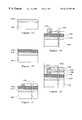
- FIGS. 1A-1E illustrate a typical process flow used to fabricate the sensors of the present invention.
- FIGS. 2A-2F show the effects of various contact on a glidehead of the present invention.
- FIGS. 3A and 3B show an embodiment of a sensor array as formed on a glidehead of the present invention.
- the sensor of the present invention may easily be fabricated using any of the techniques known in the art of microchip fabrication. In fact, due to the relatively large size of the sensors and their interconnects (well in excess of 1 ⁇ m) fabrication processes which are now approaching obsolescence for microchip fabrication find renewed life when used to fabricate the present invention. An example of a typical process flow is illustrated in FIGS. 1A-1E below.
- FIG. 1A shows a picoslider (approximately 1.25 mm ⁇ 1 mm ⁇ 0.3 mm) in preparation for sensor fabrication.
- the present invention can be fabricated directly on a standard Al 2 O 3 .TiC slider ( 100 ).
- a thin layer of polysilicon ( 110 ) is deposited using low pressure chemical vapor deposition (LPCVD). This layer ( 110 ) is typically greater than about 100 ⁇ thick.
- a second layer comprised of dielectric material ( 120 ) is then formed.
- a preferred embodiment uses a SiO 2 formed by thermal oxidation of the polysilicon layer (as shown in FIG. 1 B).
- dielectrics such as silicon nitride or silicon oxynitride may be deposited using LPCVD to form the dielectric material ( 120 ).
- the dielectric layer ( 120 ) is formed to a thickness sufficient to electrically isolate subsequently formed layers from the underlying slider and polysilicon.
- the dielectric layer ( 120 ) is pattern masked with photoresist (not shown). The pattern allows the formation of a lower electrode ( 135 ) and the lower electrode interconnects ( 130 ) (as shown in FIG. 1 C).
- the electrode and interconnects are made of conducting materials which include, but are not limited to, polysilicon, doped polysilicon, silicides, and metals. A preferred material is aluminum.
- the surface is masked again (not shown) and ZnO ( 140 ) is sputtered onto the electrode ( 135 ) to a thickness of approximately 2 ⁇ m (as shown in FIG. 1 D).
- the mask is removed.
- pure Zn metal can be sputtered onto the electrode ( 135 ).
- the Zn is later thermally oxidized to form piezoelectric ZnO.
- the ZnO ( 140 ) can be masked while an optional layer of electrically isolating material ( 150 ) is formed on the surface (as shown in FIG. 1 E).
- This isolating layer prevents subsequently formed interconnects from shorting with the lower electrode interconnects ( 130 ).
- the isolation layer ( 150 ) is comprised of SiO 2 but may be practiced using other electrically isolating materials (such as silicon nitride, silicon oxynitride, boropolysilicate glass, etc.). Shorting may also be avoided by forming subsequent interconnects such that they do not overlap with previously formed lower electrode interconnects ( 130 ).
- the surface is masked again and a layer of electrically conducting material is formed over the ZnO sensor ( 140 ), as the top electrode ( 165 ), and as top electrode interconnects ( 160 ).
- the preferred material is Al, but any conducting material will serve the purposes of the present invention, including, but not limited to, polysilicon, doped polysilicon, suicides, and metal.
- the top can be covered with an optional passivation/protection layer ( 170 ), which is composed of electrically isolating material, typically comprised of SiO 2 .
- FIGS. 2A-2F show a series of glideheads subject to typical deformation patterns caused by impacts with asperities on a disk surface.
- the X-axis represents horizontal motion with the Y-axis representing vertical motion.
- Each impact causes vibrational modes in the glidehead. These modes are dependent on how asperities impact and deform a glidehead during use.
- Each of the torsional and bending shapes depicted have specific natural resonant frequencies (or modes) which may be used to analyze asperities on the disk surface.
- sensors must be placed at a variety of locations in order to fully analyze the impact of each asperity.
- FIG. 3A shows an overhead view of a preferred embodiment of the present invention as fabricated by the previously described method.
- FIG. 3B is a perspective of the same slider and sensors.
- FIG. 3B shows five ZnO sensors ( 310 , 310 T) fabricated on a Al 2 O 3 .TiC slider ( 300 ).
- the comer sensor ( 310 ) dimensions are variable and may be as large as 100 ⁇ m ⁇ 100 ⁇ m ⁇ 2 ⁇ m, but, typically are 100 ⁇ m ⁇ 20 ⁇ m ⁇ 2 ⁇ m.
- These sensors ( 310 ) are each located on or near the four corners of the glidehead.
- Electrical interconnects ( 320 ) connect each sensor to analyzing instrumentation (not shown) through connection site ( 330 ).
- the bottom electrode ( 135 of FIG. 1E) is grounded.
- the top electrode is typically connected to amplification circuits (not shown) which amplify the signal during signal processing.
- a somewhat larger sensor ( 310 T) may be fabricated and used to detect flexing stress or temperature variation in the slider.
- the larger sensor ( 310 T) is fabricated onto the side surface of the glidehead. The length dimension of this sensor may be quite long, extending nearly the entire width of the slider ( 300 ).
- This sensor is also connected using an interconnect ( 320 ).
- the fabrication methods used to construct sensors ( 310 ) are largely the same for sensor ( 310 T).
- the signals sent by the five sensors can be processed by using any of a number of methods known in the art.
- a typical example is set forth in U.S. Pat. No. 5,581,021 by Flechsig, et al.
- the sensors of the present invention sense vibrational response of the sliders to contact with disk asperities, while by careful frequency (or mode) selection the signal-to-noise ratio is enhanced.
- Such techniques provide an accurate picture of the disk surface.
Abstract
Description
Claims (3)
Priority Applications (2)
| Application Number | Priority Date | Filing Date | Title |
|---|---|---|---|
| US09/122,194 US6314799B1 (en) | 1997-07-25 | 1998-07-23 | Advanced glidehead sensor for small slider |
| US09/981,533 US6557399B1 (en) | 1997-07-25 | 2001-10-16 | Advanced glidehead sensor for small slider |
Applications Claiming Priority (2)
| Application Number | Priority Date | Filing Date | Title |
|---|---|---|---|
| US5378197P | 1997-07-25 | 1997-07-25 | |
| US09/122,194 US6314799B1 (en) | 1997-07-25 | 1998-07-23 | Advanced glidehead sensor for small slider |
Related Child Applications (1)
| Application Number | Title | Priority Date | Filing Date |
|---|---|---|---|
| US09/981,533 Division US6557399B1 (en) | 1997-07-25 | 2001-10-16 | Advanced glidehead sensor for small slider |
Publications (1)
| Publication Number | Publication Date |
|---|---|
| US6314799B1 true US6314799B1 (en) | 2001-11-13 |
Family
ID=26732236
Family Applications (2)
| Application Number | Title | Priority Date | Filing Date |
|---|---|---|---|
| US09/122,194 Expired - Lifetime US6314799B1 (en) | 1997-07-25 | 1998-07-23 | Advanced glidehead sensor for small slider |
| US09/981,533 Expired - Fee Related US6557399B1 (en) | 1997-07-25 | 2001-10-16 | Advanced glidehead sensor for small slider |
Family Applications After (1)
| Application Number | Title | Priority Date | Filing Date |
|---|---|---|---|
| US09/981,533 Expired - Fee Related US6557399B1 (en) | 1997-07-25 | 2001-10-16 | Advanced glidehead sensor for small slider |
Country Status (1)
| Country | Link |
|---|---|
| US (2) | US6314799B1 (en) |
Cited By (1)
| Publication number | Priority date | Publication date | Assignee | Title |
|---|---|---|---|---|
| US20080074116A1 (en) * | 2006-09-26 | 2008-03-27 | Samsung Electronics Co., Ltd. | Advanced air bearing and detection method for media glide testing at ultra-low flying height |
Families Citing this family (4)
| Publication number | Priority date | Publication date | Assignee | Title |
|---|---|---|---|---|
| JP3917409B2 (en) * | 2001-11-16 | 2007-05-23 | 富士通株式会社 | Head slider and disk device |
| US7564649B2 (en) * | 2005-04-27 | 2009-07-21 | Seagate Technology Llc | Head assembly having a sensing element to provide feedback for head-media instability |
| US8310779B2 (en) * | 2005-04-27 | 2012-11-13 | Seagate Technology Llc | Head assembly having a sensing element |
| JP2008176849A (en) * | 2007-01-17 | 2008-07-31 | Fujitsu Ltd | Inspection head used for inspection device for magnetic disk |
Citations (4)
| Publication number | Priority date | Publication date | Assignee | Title |
|---|---|---|---|---|
| US5581021A (en) | 1993-12-27 | 1996-12-03 | International Business Machines Corporation | Method and apparatus for optimizing piezoelectric surface asperity detection sensor |
| US5808184A (en) * | 1997-01-15 | 1998-09-15 | Seagate Technology, Inc. | Thermal asperity sensor head with multiple spaced asperity sensors |
| US5872311A (en) * | 1996-11-13 | 1999-02-16 | Seagate Technology, Inc. | Integrated piezoelectric and thermal asperity transducers for testing disc media in high performance disc drives |
| US5942680A (en) * | 1997-04-22 | 1999-08-24 | Seagate Technology, Inc. | Multi-impact asperity sensor and burnish head |
Family Cites Families (1)
| Publication number | Priority date | Publication date | Assignee | Title |
|---|---|---|---|---|
| US6196062B1 (en) * | 1999-05-20 | 2001-03-06 | Seagate Technology Llc | Trailing edge acoustic emission sensor and pyroelectric sensor for asperity detection |
-
1998
- 1998-07-23 US US09/122,194 patent/US6314799B1/en not_active Expired - Lifetime
-
2001
- 2001-10-16 US US09/981,533 patent/US6557399B1/en not_active Expired - Fee Related
Patent Citations (4)
| Publication number | Priority date | Publication date | Assignee | Title |
|---|---|---|---|---|
| US5581021A (en) | 1993-12-27 | 1996-12-03 | International Business Machines Corporation | Method and apparatus for optimizing piezoelectric surface asperity detection sensor |
| US5872311A (en) * | 1996-11-13 | 1999-02-16 | Seagate Technology, Inc. | Integrated piezoelectric and thermal asperity transducers for testing disc media in high performance disc drives |
| US5808184A (en) * | 1997-01-15 | 1998-09-15 | Seagate Technology, Inc. | Thermal asperity sensor head with multiple spaced asperity sensors |
| US5942680A (en) * | 1997-04-22 | 1999-08-24 | Seagate Technology, Inc. | Multi-impact asperity sensor and burnish head |
Non-Patent Citations (1)
| Title |
|---|
| Bhushan, Bharat (Editor, American Society of Mechanical Engineers), "Advances in Information Storage Systems", vol. 5, pp. 211-236, 1993, New York. |
Cited By (1)
| Publication number | Priority date | Publication date | Assignee | Title |
|---|---|---|---|---|
| US20080074116A1 (en) * | 2006-09-26 | 2008-03-27 | Samsung Electronics Co., Ltd. | Advanced air bearing and detection method for media glide testing at ultra-low flying height |
Also Published As
| Publication number | Publication date |
|---|---|
| US6557399B1 (en) | 2003-05-06 |
Similar Documents
| Publication | Publication Date | Title |
|---|---|---|
| US6196062B1 (en) | Trailing edge acoustic emission sensor and pyroelectric sensor for asperity detection | |
| US5423207A (en) | Advanced PZT glide head design and implementation for a small slider | |
| US6311551B1 (en) | Method for determining characteristics of an asperity based upon detection members having a unique vibration frequency | |
| US5581021A (en) | Method and apparatus for optimizing piezoelectric surface asperity detection sensor | |
| US6889555B1 (en) | Magnetoresistive semiconductor pressure sensors and fingerprint identification/verification sensors using same | |
| US6092412A (en) | Glide height test signal processor and method using increased high frequency components | |
| US6079088A (en) | Method of fabricating a data storage system head slider having an internal accelerometer | |
| US6293135B1 (en) | Method of calibrating a system for detecting contact of a glide head with a recording media surface | |
| CA2338374C (en) | Method of manufacturing a capacitive ultrasound transducer | |
| US20050280944A1 (en) | Method for providing electrical crossover in laminated structure | |
| US7312941B2 (en) | Disk drive with head-disk interaction sensor integrated with suspension | |
| EP2164281A1 (en) | Acoustic sensor | |
| US6046596A (en) | Capacitance probe for magnetic recording head transducer to disc surface spacing measurement | |
| US6314799B1 (en) | Advanced glidehead sensor for small slider | |
| US5880587A (en) | Method and apparatus for performing in file slider take-off measurements through tuned external AE detection | |
| US6046871A (en) | Magnetic recording head slider with piezoelectric sensor for measuring slider to disc interference levels | |
| US5872311A (en) | Integrated piezoelectric and thermal asperity transducers for testing disc media in high performance disc drives | |
| Zeng et al. | Dynamics of the unload process for negative pressure sliders | |
| US6094973A (en) | Method and apparatus for mechanical screening of magnetic recording disk drives | |
| US5526687A (en) | Semiconductor acceleration sensor and testing method thereof | |
| US6185993B1 (en) | Single sided sensor for glide height testing | |
| US6269687B1 (en) | Force sensing slider | |
| Harris et al. | MEMS-based high-frequency vibration sensors | |
| US6021666A (en) | Determining a close point for glide heads | |
| US5915271A (en) | Head/disc force transducer |
Legal Events
| Date | Code | Title | Description |
|---|---|---|---|
| AS | Assignment |
Owner name: SEAGATE TECHNOLOGY, INC., CALIFORNIA Free format text: ASSIGNMENT OF ASSIGNORS INTEREST;ASSIGNORS:KU, CHIAO-PING;MARCHON, BRUNO JEAN;REEL/FRAME:009341/0575 Effective date: 19980721 |
|
| AS | Assignment |
Owner name: SEAGATE TECHNOLOGY LLC, CALIFORNIA Free format text: ASSIGNMENT OF ASSIGNORS INTEREST;ASSIGNOR:SEAGATE TECHNOLOGY, INC.;REEL/FRAME:010983/0344 Effective date: 20000628 |
|
| STCF | Information on status: patent grant |
Free format text: PATENTED CASE |
|
| CC | Certificate of correction | ||
| AS | Assignment |
Owner name: JPMORGAN CHASE BANK, AS COLLATERAL AGENT, NEW YORK Free format text: SECURITY AGREEMENT;ASSIGNOR:SEAGATE TECHNOLOGY LLC;REEL/FRAME:013177/0001 Effective date: 20020513 Owner name: JPMORGAN CHASE BANK, AS COLLATERAL AGENT,NEW YORK Free format text: SECURITY AGREEMENT;ASSIGNOR:SEAGATE TECHNOLOGY LLC;REEL/FRAME:013177/0001 Effective date: 20020513 |
|
| FPAY | Fee payment |
Year of fee payment: 4 |
|
| AS | Assignment |
Owner name: SEAGATE TECHNOLOGY LLC, CALIFORNIA Free format text: RELEASE OF SECURITY INTERESTS IN PATENT RIGHTS;ASSIGNOR:JPMORGAN CHASE BANK, N.A. (FORMERLY KNOWN AS THE CHASE MANHATTAN BANK AND JPMORGAN CHASE BANK), AS ADMINISTRATIVE AGENT;REEL/FRAME:016958/0294 Effective date: 20051130 |
|
| FPAY | Fee payment |
Year of fee payment: 8 |
|
| AS | Assignment |
Owner name: JPMORGAN CHASE BANK, N.A., AS ADMINISTRATIVE AGENT Free format text: SECURITY AGREEMENT;ASSIGNORS:MAXTOR CORPORATION;SEAGATE TECHNOLOGY LLC;SEAGATE TECHNOLOGY INTERNATIONAL;REEL/FRAME:022757/0017 Effective date: 20090507 Owner name: WELLS FARGO BANK, NATIONAL ASSOCIATION, AS COLLATE Free format text: SECURITY AGREEMENT;ASSIGNORS:MAXTOR CORPORATION;SEAGATE TECHNOLOGY LLC;SEAGATE TECHNOLOGY INTERNATIONAL;REEL/FRAME:022757/0017 Effective date: 20090507 |
|
| AS | Assignment |
Owner name: SEAGATE TECHNOLOGY INTERNATIONAL, CALIFORNIA Free format text: RELEASE;ASSIGNOR:JPMORGAN CHASE BANK, N.A., AS ADMINISTRATIVE AGENT;REEL/FRAME:025662/0001 Effective date: 20110114 Owner name: MAXTOR CORPORATION, CALIFORNIA Free format text: RELEASE;ASSIGNOR:JPMORGAN CHASE BANK, N.A., AS ADMINISTRATIVE AGENT;REEL/FRAME:025662/0001 Effective date: 20110114 Owner name: SEAGATE TECHNOLOGY LLC, CALIFORNIA Free format text: RELEASE;ASSIGNOR:JPMORGAN CHASE BANK, N.A., AS ADMINISTRATIVE AGENT;REEL/FRAME:025662/0001 Effective date: 20110114 Owner name: SEAGATE TECHNOLOGY HDD HOLDINGS, CALIFORNIA Free format text: RELEASE;ASSIGNOR:JPMORGAN CHASE BANK, N.A., AS ADMINISTRATIVE AGENT;REEL/FRAME:025662/0001 Effective date: 20110114 |
|
| AS | Assignment |
Owner name: THE BANK OF NOVA SCOTIA, AS ADMINISTRATIVE AGENT, Free format text: SECURITY AGREEMENT;ASSIGNOR:SEAGATE TECHNOLOGY LLC;REEL/FRAME:026010/0350 Effective date: 20110118 |
|
| FPAY | Fee payment |
Year of fee payment: 12 |
|
| AS | Assignment |
Owner name: SEAGATE TECHNOLOGY INTERNATIONAL, CAYMAN ISLANDS Free format text: TERMINATION AND RELEASE OF SECURITY INTEREST IN PATENT RIGHTS;ASSIGNOR:WELLS FARGO BANK, NATIONAL ASSOCIATION, AS COLLATERAL AGENT AND SECOND PRIORITY REPRESENTATIVE;REEL/FRAME:030833/0001 Effective date: 20130312 Owner name: SEAGATE TECHNOLOGY US HOLDINGS, INC., CALIFORNIA Free format text: TERMINATION AND RELEASE OF SECURITY INTEREST IN PATENT RIGHTS;ASSIGNOR:WELLS FARGO BANK, NATIONAL ASSOCIATION, AS COLLATERAL AGENT AND SECOND PRIORITY REPRESENTATIVE;REEL/FRAME:030833/0001 Effective date: 20130312 Owner name: SEAGATE TECHNOLOGY LLC, CALIFORNIA Free format text: TERMINATION AND RELEASE OF SECURITY INTEREST IN PATENT RIGHTS;ASSIGNOR:WELLS FARGO BANK, NATIONAL ASSOCIATION, AS COLLATERAL AGENT AND SECOND PRIORITY REPRESENTATIVE;REEL/FRAME:030833/0001 Effective date: 20130312 Owner name: EVAULT INC. (F/K/A I365 INC.), CALIFORNIA Free format text: TERMINATION AND RELEASE OF SECURITY INTEREST IN PATENT RIGHTS;ASSIGNOR:WELLS FARGO BANK, NATIONAL ASSOCIATION, AS COLLATERAL AGENT AND SECOND PRIORITY REPRESENTATIVE;REEL/FRAME:030833/0001 Effective date: 20130312 |