US6314468B1 - System and method for managing transmission of electronic data between trading partners - Google Patents
System and method for managing transmission of electronic data between trading partners Download PDFInfo
- Publication number
- US6314468B1 US6314468B1 US09/212,208 US21220898A US6314468B1 US 6314468 B1 US6314468 B1 US 6314468B1 US 21220898 A US21220898 A US 21220898A US 6314468 B1 US6314468 B1 US 6314468B1
- Authority
- US
- United States
- Prior art keywords
- message
- network entity
- data
- edi
- electronic
- Prior art date
- Legal status (The legal status is an assumption and is not a legal conclusion. Google has not performed a legal analysis and makes no representation as to the accuracy of the status listed.)
- Expired - Lifetime
Links
Images


Classifications
-
- H—ELECTRICITY
- H04—ELECTRIC COMMUNICATION TECHNIQUE
- H04L—TRANSMISSION OF DIGITAL INFORMATION, e.g. TELEGRAPHIC COMMUNICATION
- H04L63/00—Network architectures or network communication protocols for network security
- H04L63/04—Network architectures or network communication protocols for network security for providing a confidential data exchange among entities communicating through data packet networks
- H04L63/0428—Network architectures or network communication protocols for network security for providing a confidential data exchange among entities communicating through data packet networks wherein the data content is protected, e.g. by encrypting or encapsulating the payload
-
- H—ELECTRICITY
- H04—ELECTRIC COMMUNICATION TECHNIQUE
- H04L—TRANSMISSION OF DIGITAL INFORMATION, e.g. TELEGRAPHIC COMMUNICATION
- H04L63/00—Network architectures or network communication protocols for network security
- H04L63/12—Applying verification of the received information
- H04L63/123—Applying verification of the received information received data contents, e.g. message integrity
-
- H—ELECTRICITY
- H04—ELECTRIC COMMUNICATION TECHNIQUE
- H04L—TRANSMISSION OF DIGITAL INFORMATION, e.g. TELEGRAPHIC COMMUNICATION
- H04L63/00—Network architectures or network communication protocols for network security
- H04L63/16—Implementing security features at a particular protocol layer
- H04L63/166—Implementing security features at a particular protocol layer at the transport layer
-
- H—ELECTRICITY
- H04—ELECTRIC COMMUNICATION TECHNIQUE
- H04L—TRANSMISSION OF DIGITAL INFORMATION, e.g. TELEGRAPHIC COMMUNICATION
- H04L67/00—Network arrangements or protocols for supporting network services or applications
- H04L67/01—Protocols
- H04L67/12—Protocols specially adapted for proprietary or special-purpose networking environments, e.g. medical networks, sensor networks, networks in vehicles or remote metering networks
-
- H—ELECTRICITY
- H04—ELECTRIC COMMUNICATION TECHNIQUE
- H04L—TRANSMISSION OF DIGITAL INFORMATION, e.g. TELEGRAPHIC COMMUNICATION
- H04L69/00—Network arrangements, protocols or services independent of the application payload and not provided for in the other groups of this subclass
- H04L69/30—Definitions, standards or architectural aspects of layered protocol stacks
- H04L69/32—Architecture of open systems interconnection [OSI] 7-layer type protocol stacks, e.g. the interfaces between the data link level and the physical level
- H04L69/322—Intralayer communication protocols among peer entities or protocol data unit [PDU] definitions
- H04L69/329—Intralayer communication protocols among peer entities or protocol data unit [PDU] definitions in the application layer [OSI layer 7]
Definitions
- the present invention relates generally to the field of telecommunications and more specifically to a method, system and computer program product for managing transmission of electronic data between two network entities.
- the present invention relates more specifically to a method, system and computer program product for managing transmission of electronic data between network entities of trading partners using Transmission Control Protocol/Internet Protocol (“TCP/IP”) and Secure Sockets Layer, Version 3 (“SSL3”). More specifically, the present invention relates to a method, system and computer program product for managing transmission of data formatted compatible with Electronic Data Interchange (“EDI”) in transactions using TCP/IP and SSL3 between network entities.
- TCP/IP Transmission Control Protocol/Internet Protocol
- SSL3 Secure Sockets Layer, Version 3
- TCIF Telecommunications Industry Forum
- the International Telecommunication Union (“ITU”) is a treaty based organization operating under the auspices of UNICEF (a branch of the United Nations).
- the ITU's primary mission is to study, promote, initiate and design global telecommunication services and technology to improve the quality of life for all of the world's inhabitants.
- WTSC World Telecommunication Service Conference
- ITU-T Technology sector
- ITU-R Radio sector
- ITU-TSB Telecom Service Bureau sector
- ASN.1 Information Technology - Abstract Syntax Notation One
- RSA Laboratories a division of RSA Data Security, Inc. has published PKCS #7 , Public-Key Cryptography Standards # 7 —Cryptographic Message Syntax , which is incorporated herein by reference.
- FIG. 1 is a block diagram of a point-to-point network configuration.
- a network node A 10 is directly connected to a network node B 16 , which is directly connected to a network node C 12 and a network node D 14 .
- messages from node A 10 to node C 12 are transmitted from node A 10 to node B 16 and are then transmitted to node C 12 .
- a point-to-point configuration is a communications link in which dedicated links exist between individual origins and destinations, as opposed to a point-to-multipoint, in which the same signal goes to many destinations (such as a cable TV system), or a switched configuration, in which the signal moves from the original to a switch that routes the signal to one of several possible destinations.
- FIG. 2 is a block diagram of a Value Added Network (“VAN”) 28 , having network node A 20 , network node B 22 , network node C 24 and network node D 26 connected to the network.
- VAN Value Added Network
- node A 20 sends a message to the VAN 28 which encodes the message in a standard format for transmission to a server which communicates the message in a proper format for receipt by network node B 22 .
- a VAN is a communications network that offers additional services, such as message routing, resource management, and conversion facilities, for computers communicating at different speeds or using different protocols.
- a connection e.g., a modem-to-modem connection
- the data has been transmitted
- the connection has been terminated (e.g., via a modem-to-modem disconnect) in order to communicate the end of transmission of the message.
- Connecting via a dial-up modem involves a connection similar to a user dialing a telephone.
- a telephone company sends a ring signal.
- a modem detects the ring signal and starts transmitting a signal to establish a connection by setting up a carrier frequency and modulation.
- the recipient modem signals a computer, through a wire lead connecting the modem to the computer, that the modem has detected a ring signal.
- the computer has software routines which accept this information and issue commands to turn on a terminal ready lead.
- the connection is then established for transmission of data.
- Receiving modems “listen” for carrier signals on predetermined frequencies.
- a receiving modem detects a carrier, which is a transmitted voltage
- the receiving modem sends a carrier detect signal to its attached computer
- software routines in the computer recognize that a connection has been established.
- a receiving modem translates a received stream of data from a modulated frequency signal into a stream of digital bits to be transmitted to the attached computer.
- the computer then typically stores received bits one by one in a register until, for example, eight bits, or a byte, have been received. The byte thus received is then processed as a received byte of information. The process continues until a disconnect signal is received.
- Telephone carriers have voice channels devoted to voice data and signaling channels for data which is not voice grade. Telephony standards establish a path over which these types of data are transmitted to a receiver, giving a user a “physical connection,” or an established path over telephone lines, which is used to transmit a stream of data in this setting to an intended recipient.
- a sender When a sender has completed transmission of a message, the sender disconnects, very similarly to hanging up a telephone. The sender turns off the data terminal lead, dropping the carrier signal. The recipient then detects the lack of carrier signal being received and issues a signal such as “carrier lost” to disconnect from the telephone line. Each modem may then reset for its next connection.
- a recipient has had no way to know how much data was being transmitted until the connection was terminated. Therefore, once a sender initiated a connection and began transmission of a message, the receiver simply accepted transmission until a disconnect was received. The receiver could then interpret the stream as received to be the entire message. If a sender desired to transmit secure data by means of encryption, the sender and receiver typically had to agree to an encryption technique. The sender could then encrypt the sensitive portion of the message to be transmitted, and send it as an attachment to a non-secure message. Again, the receiver only recognized that the complete message had been received by recognizing the end of transmission of the message.
- a sender network entity and receiver network entity each have a distinct address on the network.
- a message to be transmitted from the sender network entity to the receiver network entity is partitioned into a plurality of packets, each of which includes a network destination address of the receiver network entity. The packets are then transmitted individually, to be received and pieced together back into the original message by the receiving network entity.
- the packets are routed through multiple network nodes, each of which examine the packets to determine whether the network node is the intended receiver network entity, or a host of the intended receiver network entity. Therefore, the transmitted data is insecure unless some form of encryption has been used to encrypt the data in the packet before transmission.
- EDI data has conventionally been transmitted only in its pure form.
- a sender has conventionally established a connection with a receiver, transmitted the EDI message, and then terminated the connection. Termination of the connection has been accomplished by a disconnect (e.g., a modem-to-modem disconnect).
- the receiver of EDI data has heretofore had no way of knowing the length of the message being transmitted, since the end of the message has been identified by the termination of the connection. However, the receiver of EDI data has heretofore had no need to know the length of the message being transmitted.
- EDI data protocol does not inherently support encryption. Therefore, EDI data transmitted over a non-secure line, such as the Internet, is insecure because (1) a third party may be able to intercept data during transmission and (2) a third party may be able to alter the data being transmitted.
- a digital signature is a personal authentication method based on encryption and secret authorization codes used for “signing” electronic documents.
- Encryption techniques generally have been utilized for secure transmission of many types of data
- Rivest-Shamir-Adleman (“RSA”) encryption is a public key encryption algorithm which is well known in the art of data transmission.
- the RSA technique is disclosed in U.S. Pat. No. 4,405,829, the teachings of which are hereby incorporated by reference in their entirety.
- SHA Secure Hash Algorithm
- a method and system for providing secure EDI over an open network by using an RSA type cryptographic system is disclosed in U.S. Pat. No. 5,812,669. The method and system uses an EDI AUTACK, or EDI acknowledgment message, as a document to provide the digital signature in a public/private key system in which the AUTACK is signed by an encrypted hash code which has been encrypted with the sender's private key.
- a problem with using an encryption technique such as SSL3 is that the receiver typically must know the length of an encrypted message which is being transmitted in order to recognize when the encrypted message ends and thereby terminate the decryption.
- EDI users have felt a need to transmit only EDI data. Therefore, the EDI community has resisted the inclusion of any header or trailer data. In fact, proposals to add header and/or trailer data to EDI formatted data have been rejected by members of the EDI community.
- the present inventor has identified at least two problems that have prevented secure transmission of EDI formatted data between two network entities over public lines using TCP/IP and SSL3,namely (1) a need for destination address information and (2) a need for length information to be included in a transmitted message.
- the present inventor has identified a need for a method and system of managing transmission of electronic data in EDI format between network entities over dedicated circuits or Wide Area Networks (“WANs”).
- WANs Wide Area Networks
- an object of this invention is to provide a novel method, system and computer program product for managing transmission of electronic data between two network entities.
- EDI Electronic Data Interchange
- TCP/IP Transmission Control Protocol/Internet Protocol
- SSL3 Secure Sockets Layer, Version 3
- the message format identifier corresponds to one of a basic EDI message, an EDI message with message integrity, an EDI message with non-repudiation, an Interactive Agent (“IA”) status, and an IA message receipt.
- Message trailers may also be appended to include information, for example, for digital signatures and message digests.
- the present invention provides a hardware and software platform to effect the secure transmission of EDI messages from one network entity to another.
- an EDI translator of a first network entity receives an ANSI X.12 EDI transaction, the transaction is passed to a first IA.
- the first IA accepts the ANSI X.12 EDI transaction from the EDI translator, sets up a secure connection using TCP/IP and SSL3,formats an electronic message having a header portion and a message data portion, transmits the electronic message to an IA of a second network entity, and disconnects.
- the IA of the second network entity receives the transmission, recognizes the header portion and the message data portion of the transmitted electronic message, and passes the transaction to an EDI translator of the second network entity for processing.
- Object identifiers are used in message transmission, for example, to identify a type of message being transmitted, encryption techniques used for encrypting the transmitted message, and hash algorithms used for message digests.
- lengths of message data portions and object identifiers are used in transmitted electronic messages, greater versatility of transmission is possible, as, for example, different encryption algorithms may be utilized in different transmissions of electronic messages between network entities.
- FIG. 1 is a network diagram for a conventional network having point-to-point connectivity
- FIG. 2 is a network diagram for a conventional Value Added Network (“VAN”) showing connectivity to end users;
- VAN Value Added Network
- FIG. 3 is a network diagram for the novel interface between two network entities according to one embodiment of the invention.
- FIG. 4 is a network diagram for the novel interface for the Interactive Agent according to a second embodiment of the present invention.
- FIG. 5 is a block diagram for the client server relationship in a network according to the invention.
- FIG. 6 is a block diagram of a data format for a message to be transmitted according to one embodiment
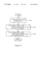
- FIGS. 7 a , 7 b , 7 c , 7 d , 7 e , 7 f , 7 g and 7 h are process flow diagrams of the method for the flow of data between a client and a server;
- FIG. 8 a is a block diagram of a format for a basic Electronic Data Interchange (“EDI”) message for the invention
- FIG. 8 b is a block diagram of an EDI message with message integrity for the invention.
- FIG. 8 c is a block diagram of a format for an EDI message with nonrepudiation for the invention.
- FIG. 8 d is a block diagram of a format for an Interactive Agent (“IA”) Status message for the invention.
- IA Interactive Agent
- FIG. 9 a is a block diagram of a format for a basic EDI message for the invention.
- FIG. 9 b is a block diagram of a format for an EDI message with message integrity for the invention.
- FIG. 9 c is a block diagram for an EDI message with non-repudiation for the invention.
- FIG. 9 d is a block diagram of a format for an IA Status message for the invention.
- FIG. 10 a is a block diagram of a format for an optional basic receipt message for the present invention.
- FIG. 10 b is a block diagram of a format for a receipt with message integrity for the present invention.
- FIG. 10 c is a block diagram for a format for a receipt with digital signature with non-repudiation for the invention.
- FIG. 11 illustrates the syntax for basic EDI messages and object identifiers for basic EDI messages
- FIG. 12 illustrates the syntax for EDI messages with message integrity and object identifiers for EDI messages with message integrity
- FIG. 13 a illustrates the syntax for EDI messages with non-repudiation
- FIG. 13 b illustrates the syntax for object identifiers referenced by EDI messages with non-repudiation
- FIG. 14 illustrates the syntax for IA Status messages for the present invention
- FIG. 15 illustrates the syntax for optional IA Receipts and object identifiers referenced by IA Receipt messages for the invention
- FIG. 16 illustrates exemplary computer code for an Open Socket operation for creating a socket
- FIG. 17 illustrates exemplary computer software code for initializing a server for the invention
- FIGS. 18 a- 18 b are a process flow chart for an exemplary method for parsing incoming messages by an Interactive Agent according to the invention
- FIG. 19 is a process flow chart for an exemplary method for parsing a basic EDI message according to the invention.
- FIGS. 20 a- 20 e are a process flow chart for an exemplary method for parsing an EDI message with message integrity
- FIGS. 21 a- 21 k are a process flow chart for an exemplary method for parsing an EDI message with non-repudiation according to the invention.
- FIG. 22 is a process flow chart for parsing an IA Status message according to the invention.
- FIGS. 23 a- 23 c are a process flow chart for parsing an IA Receipt according to the invention.
- FIG. 24 a illustrates an exemplary portion of a generalized computer system upon which portions of the invention may be implemented.
- FIG. 24 b illustrates an exemplary portion of a generalized hardware configuration, in the format of a workstation, upon which portions of the invention may be implemented.
- An Operations Support System (“OSS”) 30 for the network entity A of a trading partner communicates with a Service Center Gateway (“SCG”) 32 , which communicates, through an Internet Protocol (“IP”) network 34 which is in communication with a firewall 36 , communicating through a T 1 connection 38 to a network 40 .
- the network 40 communicates through a T 1 connection 42 with a firewall 44 in communication with an IP network 46 which communicates with an SCG 48 which communicates with an OSS 50 of a network entity B of a trading partner.
- the SCG 32 may consist of two components, an EDI gateway and a TCP/IP with SSL3 transport module.
- FIG. 4 is a network diagram for a second embodiment of the present invention.
- An OSS 30 for a network entity of a trading partner A communicates with an EDI translator 102 for translating incoming and outgoing EDI messages.
- the EDI translator 102 communicates with an EDI Communications Transporter (“EDICT”) 104 , which communicates with a firewall 106 , which is in communication with a network 108 .
- the network 108 is in turn in communication with a firewall 110 , which communicates with an EDICT 112 , in communication with an EDI translator 114 , which translates incoming and outgoing EDI messages for an OSS 50 for a network entity of a trading partner B.
- EDICT EDI Communications Transporter
- FIG. 5 is a block diagram showing an overall network set-up of two network entities of two respective trading partners communicating with each other.
- Company A 120 has a client 122 communicating with a server 126 of a company B 130 .
- Company B 130 has a Client 128 communicating with a Server 124 of Company A 120 .
- the Interactive Agent functions as an interface between the EDI translator and data communications protocols. Various implementation approaches may be taken ranging from a simple application programming interface (“API”) through a standalone programming application.
- API application programming interface
- the underlying structure of the Interactive Agent is a symmetrical Client/Server configuration where both the Client and Server functions are required at each implementation. As shown in FIG. 3, a gateway for a network entity of trading partner A and a gateway for a network entity of trading partner B communicate via a frame relay network with T1 access lines.
- An IA process sends and receives data using SSL3 libraries.
- interactions with the SSL3 libraries are in the form of SSL3 tool-kit functions.
- each IA server should provide up to a maximum of 16 concurrent connections per network entity by using such technical approaches as multi-processing, multi-threading, or other comparable technology.
- each SSL3 connection should support the transfer of a single EDI message.
- a session should exist only for the duration of a single EDI message, avoiding the potential of orphaned processes or sockets which may only be cleared by either an interruption in the client/server processes or a restart of the computing platform.
- FIG. 6 is a block diagram of a format for a message to be transmitted between the network entity of trading partner A and the network entity of trading partner B of FIG. 3 .
- the message 140 includes a 48-byte header followed by a message in EDI format. This message format was designed for messages to be transmitted over the network configuration discussed previously with regard to FIG. 3.
- a 48-byte header communicates information about the EDI message so that a receiver can receive and decode an encrypted message.
- An op_code 142 occupies the first eight bytes of the transmitted message. All information in the 48-byte header is in ASCII text format.
- the first byte of the 8-byte op_code is an operation type which has a value of “0” for Pre-order or a value of “1” for Order.
- the second byte of the op_code is an Operation Action which has a value of “0” for status only, with no message, “1” for Acknowledgment, “2” for return, or “7” for Action.
- the third and fourth bytes of the op_code are an error code having a value of “00” for no error, a value of “01” for upstream down, indicating that some server or communications capability upstream from the gateway is down, as a signal to stop sending data, a value of “02” for upstream up, indicating that the server or communications capability has been restored, or a value of “03,” indicating that a bad header has been received.
- the last four bytes of the op_code are padded with spaces.
- the next eight bytes of the header consist of a source and destination 144 .
- a source value occupies the first four bytes, having, for example, a value of “U99” for a US West re-seller ID, or, for example, a value of “M02” for an MCI re-seller ID.
- a destination value occupies the next four bytes, having, for example, a value of “U99” for a US West re-seller ID, or, for example, g 22 a value of “M02” for an MCI re-seller.
- a msg_id 146 value for a message ID occupies the next eight bytes of the header.
- the msg_id 146 will have the value of a Purchase Order Number (“PON”) for an Order, or the value of an Inquiry Number (“INQNUM”) for a pre-order.
- the next eight bytes have the value of a byte_cnt 150 , which is the value of the number of bytes in the accompanying message, excluding the header.
- a user_data field 152 occupies the next eight bytes, followed by the message data 154 , which is the stream of EDI data to be transmitted.
- FIGS. 7 a- 7 h are process flow charts showing the method for the flow of data between a client and a server.
- the server is initialized on port 7000 , to listen for transmission from the client.
- the client initiates a connection to the server, as further described below with regard to FIGS. 7 b- 7 d .
- the server accepts the connection from the client, as discussed further below with regard to FIGS. 7 e- 7 f
- “establishing a connection” in an open network such as the Internet, may involve creating a socket, which is a software technique to establish communication between nodes on a network. This is different from the conventional point-to-point techniques of modem-to-modem connects and disconnects.
- step 186 the client sends a message type/length and data to the server, as discussed further below with regard to FIG. 7 g .
- step 188 the server initiates closing the connection, as discussed further below with regard to FIG. 7 h .
- “terminating a connection” on an open network such as the Internet, may involve closing a socket connection in software while two network entities continue to communicate through other software connections over hardware communications lines. Control is then returned to the calling system.
- FIG. 7 b is a process flow chart showing the overall method for the client initiating a connection to the server, as discussed above with regard to step 182 of FIG. 7 a .
- the client accepts EDI data and destination information from an EDI translator.
- the client determines the message length of the EDI data which was accepted in step 190 as discussed above.
- the client determines an IP destination address using the destination information which was accepted in step 190 as discussed above.
- the client connects to the server, as further discussed previously with regard to step 184 of FIG. 7 a and as discussed further below with regard to FIGS. 7 c- 7 d.
- step 186 of FIG. 7 b the clients sends the message type/length and data to the server.
- step 200 of FIG. 7 b the client logs a system general serial number, a date/time, an ISA, and the destination IP address. Control is then returned to the calling system.
- FIGS. 7 c- 7 d are a process flow chart for the method of step 196 of FIG. 7 b , wherein the client connects to the server.
- the client After starting, in step 220 , the client creates an SSL context.
- a memory allocation is performed, and an opaque data structure known as a “context” is used to store cryptographic data associated with the individual connection, certificates, references to callbacks and various other data.
- An independent context must be maintained for each connection in the preferred embodiment.
- step 222 the client initializes an SSL context to initialize the internal values of the SSL context structure. This step must be performed before any other SSL Set function.
- step 224 the client reads and adds certificates from a local library. This step adds to the chain of certificates used when authenticating an SSL peer. A variation of this step adds trusted certificates to complete certificate chains.
- step 226 the client reads and adds a private key from a local source. This step specifies the private key to be used for signing and non-export key exchange. This key must match an installed public key.
- step 228 the client sets an SSL protocol version. This parameter specifies which version of the SSL protocol may be used for the connection. In the preferred embodiment, this will normally be set to SSL Version 3 only.
- step 230 of FIG. 7 d the client sets an SSL protocol side to the client. The current SSL instance is now set to be the client side of the connection. It is noted that clients may only connect to servers.
- step 240 the client opens a socket, which is an identifier for a particular service on a particular node on a network.
- a socket comprises a node address and a port number, which identifies the service. For example, port 80 on an Internet node indicates a Web server.
- a client application creates a socket and then issues a connect to a service specified in a sockaddr_in structure. Exemplary code for an open socket operation is discussed below with regard to FIG. 16 .
- step 242 of FIG. 7 d the client sets an SSL I/O reference to specify the reference parameter passed by the library to the I/O callback functions. This step configures the SSL context structure for later use.
- step 244 the client sets an SSL peer ID to uniquely identify the SSL peer associated with the current SSL connection. This set function is required in instances where session resumption capabilities are specified.
- step 246 the client initiates an SSL handshake for exchanging certificates and keys with the server.
- the client performs a “client hello” operation, comprising sending a challenge, a session ID (if any) and cipher specifications.
- client hello After receiving a “server hello,” the client will perform a “send client” master key operation to send the clients master key encrypted by the server's public key. This is only performed for an initial session and is not done for a resumed session.
- the client then performs a “client finish” operation to transmit the connection ID encrypted by the client's write key.
- the server responds with a “server verify” function followed by a request for the client's certificate.
- the client responds with its certificate data, encrypted by the client's write key.
- the server executes a “server finish” function to ready the connection for passing data.
- the receiving party Upon receiving a certificate from a peer (i.e., client or server), the receiving party sends the certificate information from the SSL3 transport layer to the receiving party's IA to be saved and used for enhanced security such as non-repudiation.
- the same key pair/certificate used for authentication to the peer system will also be used for any digital signing that is required. Peers exchanging this type of data should agree to mutually acceptable Trusted Certificate Authorities. In the preferred embodiment, only certificates issued by these Trusted Authorities are exchanged or referred to in digital signatures.
- FIGS. 7 e- 7 f are a process flow chart showing the method for the server accepting the connection from the client, as discussed previously with regard to step 184 of FIG. 7 a .
- the server creates an SSL context. Memory allocation is performed and an opaque data structure known as a context is used to store the cryptographic data associated with the current connection, certificates, references to callbacks and various other data An independent context must be maintained for each connection.
- step 252 the server initializes an SSL context, as discussed previously with regard to the client in step 222 of FIG. 7 c .
- step 254 the server reads and adds certificates from a local library, similarly to step 224 as discussed previously with regard to the client and FIG. 7 c .
- step 256 the server reads and adds a private key from a local source, similarly to step 226 discussed previously with regard to the client in FIG. 7 c .
- step 258 the server set an SSL protocol version, similarly to step 228 as discussed previously with regard to the client for FIG. 7 c.
- step 260 of FIG. 7 f the server set an SSL protocol side to server.
- the current SSL instance is set to be the server side of the connection. It is to be noted that servers may only accept connections from clients.
- step 262 the server opens a socket call similarly to step 240 as discussed previously with regard to the client for FIG. 7 d.
- step 264 the server sets an SSL I/O reference similarly to step 242 discussed previously with regard to the client and FIG. 7 d .
- step 266 the server sets an SSL peer ID, similarly to step 244 as discussed previously with regard to the client for FIG. 7 d.
- the server performs an SSL handshake to exchange certificates and keys with the client.
- the server After receiving the “client hello” from the client, as discussed previously with regard to step 246 of FIG. 7 d , the server sends a “server hello” having the connection ID and either a session ID or the server certificate and cipher specifications, depending on whether this is an initial or a resumed session.
- the server then waits for the “client finish” message to be received.
- the server responds with a “server verify,” which is a challenge encrypted with the server write key.
- the server requests a certificate from the client by sending an Auth Type Challenge encrypted by the server write key.
- the client responds with its client certificate.
- the server then sends a “server finish” message having the session ID encrypted by the server write key. This completes the process to prepare the connection to pass data. Control is then returned to the calling system.
- FIG. 7 g is a process flow chart showing the method used by the server for receiving the message type/length and data send by the client to the server as discussed previously with regard to step 186 of FIG. 7 a .
- the server reads octets of the message type and length.
- An SSL Read of 2 bytes is performed.
- the first byte is an ASN.1 tag, and the second byte defines a size of a message length field.
- the first read operation determines the number of bytes for the second read operation.
- the second read operation determines the total length of all subsequent data.
- the third read operation then reads all the subsequent data.
- these steps are accomplished using an SSL Read () function.
- step 272 of FIG. 7 g the server reads the number of bytes indicated by the message length, as discussed above with regard to step 270 . After the reads are completed, in step 274 , the server passes EDI data to a translator.
- step 276 the server logs a system general serial number, a date and time, an ISA segment, and a sender IP address which is a remote IP address and local port number. Control is then returned to step 188 , as discussed previously with regard to FIG. 7 a.
- FIG. 7 h is a process flow chart showing the method for step 188 of FIG. 7 a .
- the client selects a socket with timeout. This allows the client to determine a successful/unsuccessful transmission of data after passage of a predetermined time even though the client does not receive notice that the server has completed a socket close operation.
- the server issues an SSL close.
- the server issues a socket close and the SSL context is set to delete.
- the client similarly issues an SSL close.
- the client issues a socket close and the SSL context is set to delete. Control is then returned to the calling system.
- the SSL close function closes the SSL session with the peer. No further communications are then expected for this particular session.
- the server closes the socket connection with the socket close () function, passing the socket descriptor as a parameter.
- the SSL context delete function typically releases the resources utilized by the SSL connection. Note that this is only performed if the current session is to be terminated and is not performed for sessions that may later be resumed. Depending on implementation, the memory used by the context structure may have to be deallocated after the context delete.
- FIGS. 8 a- 8 d and FIGS. 9 a- 9 d are block diagrams showing the four formats.
- Each message type is to be encoded in accordance with Abstract Syntax Notation 1 (“ASN.1”) and its associated encoding rules Basic Encoding Rules (“PER”) and Distinguished Encoding Rules (“DER”). These rules are fully described in Rec.
- FIG. 8 a is a block diagram illustrating a format of a basic EDI message 300 .
- a first portion of the message to be transmitted is a message type and length 302 , followed by the EDI message 304 .
- FIG. 8 b is a block diagram illustrating a format for an EDI message with message integrity 320 .
- a first portion of the message 320 is a message type and length 322 , followed by the EDI message 324 , followed by a message digest 326 .
- FIG. 8 c is a block diagram illustrating a message format architecture for EDI message with non-repudiation 340 .
- a message type and length 342 is followed by the EDI message 344 , followed by a digital signature 346 .
- FIG. 8 d is a block diagram showing a message format architecture for an IA status message 360 .
- a message type and length 362 is followed by a status message 364 .
- FIGS. 9 a- 9 d are block diagrams illustrating the message formats as discussed previously with regard to FIGS. 8 a- 8 d message format architectures.
- FIG. 9 a is a block diagram of a message format for a basic EDI message 300 .
- a header 1 302 includes a message type and length.
- the EDI message 304 follows the header 1 302 .
- FIG. 9 b is a block diagram illustrating the message format for an EDI message with message integrity 320 , as discussed previously with regard to FIG. 8 b .
- a header 1 321 includes a message type and length, followed by a header 2 323 having an EDI message tag and length. Following the header 2 323 is an EDI message 324 , followed by a header 3 325 , which includes a message digest tag and length. Following the header 3 325 is a message digest 326 which is created by using a hash algorithm (SHA1).
- SHA1 hash algorithm
- the recipient After receiving a message of the type EDI with message integrity 320 , the recipient calculates a message digest of the EDI data portion 324 of the message, using the algorithm specified in the message. The calculated message digest is then compared with the message digest received with the message 320 and an exact match verified. If the message digests match, the EDI data is forwarded to the EDI translator for the recipient and a successful reception is written to a log file.
- FIG. 9 c is a block diagram illustrating a message format of an EDI message with non-repudiation 340 , as discussed previously with regard to FIG. 8 c .
- a header 1 341 includes a message type and length, followed by a header 2 343 , which includes an EDI message tag and length, followed by an EDI message 344 .
- a header 4 345 includes a digital signature tag and length, followed by a digital signature, including a hash algorithm (SHA1), a sender's certificate information, a hash encryption algorithm, and a message digest encrypted using a sender's private key.
- SHA1 hash algorithm
- the recipient After receiving a message of the type EDI with non-repudiation 340 , the recipient calculates a message digest of the EDI data portion 344 of the message, using the algorithm specified in the message. The message digest received from the sender is then decrypted using the decryption key referenced in the message. The calculated message digest is then compared with the message digest received with the message 340 and an exact match verified. If the message digests match, the EDI data is forwarded to the EDI translator for the recipient and a successful reception is written to a log file.
- FIG. 9 d is a block diagram illustrating the format of an IA status message 360 as discussed previously with regard to FIG. 8 d .
- a header 1 362 including a message type and length, is followed by an IA status 364 which is an encoded IA status.
- the IA status message consists of an identifying header and four octets (each octet consists of eight bits) containing status information.
- the first octet is utilized for status conditions pertaining to the wide area interface of the IA (i.e., TCP/IP and SSL3).
- values defined for the current embodiment include a value of 00 for NULL (no error or action) and 08 for a request for a peer to cease transmissions on inbound data stream due to problems with the Wide Area Network (“WAN”) interface.
- WAN Wide Area Network
- the second octet is utilized for status conditions pertaining to the downstream systems on the local interface (i.e., the EDI translator or other related, downstream system).
- Values defined for the current embodiment include a value of 00 for NULL and a value of 08 for a request for a peer to cease transmissions on inbound data stream due to problems with the IA communicating with an EDI translator or other downstream processing systems.
- the third and fourth octets are available for pairwise definitions. Parties to a pairwise agreement may define the values of the third and fourth octets in any manner they choose.
- the third and fourth octets be utilized to either convey their own independent meanings when the first two octets contain 00 00, or they may be used as amplifying identifiers in instances where either of the first two octets are non-zero.
- the message “00 08 00 00” is a message sent to a peer requesting no further transmission due to a downstream problem.
- a message having a value of “08 00 00 00” communicates problems with an inbound WAN, so the peer should cease transmissions.
- FIG 10 a is a block diagram illustrating the format of a basic receipt 380 .
- a header 1 382 includes a message type and length followed by an IA receipt 384 .
- the EDI message is parsed to extract the ISA segment.
- a date/time stamp is appended to the ISA forming the receipt.
- the information is formatted in accordance with the syntax to be discussed below with regard to FIG. 15, and is then returned to the originator.
- FIG 10 b is a block diagram illustrating a format for a receipt with message integrity 390 .
- a header 1 392 including a message type and length, is followed by an IA receipt 394 .
- the IA receipt 394 is followed by a header 3 396 which includes a message digest tag and length, followed by a message digest 398 which includes an SHA1 message digest algorithm. Receipts with message integrity extend the basic receipt by adding a message digest of the original EDI data.
- FIG 10 c is a block diagram illustrating a format for a receipt with digital signature (non-repudiation) 400 .
- a header 1 402 includes a message type and length, followed by an IA receipt 404 .
- a header 4 406 having a digital signature tag and length, followed by a digital signature 408 , having an SHA1 message digest algorithm and an RSA digital signature algorithm. Receipts with digital signatures extend the basic receipt of FIG 10 a by adding a digitally signed acknowledgment of the original EDI message.
- FIG. 11 illustrates a syntax for basic EDI messages and object identifiers referenced by basic EDI messages.
- a PlainEDIMessage 420 is a sequence having a content type object identifier 422 and an explicit octet string 424 which is the EDI message.
- a pkcs-7 object identifier has an ISO, a member body, a code for US, a code for rsadsi, pkcs, and 7.
- a content type object identifier 428 has a pkcs-7 as discussed above, and 1 for EDI data.
- FIG. 12 illustrates a syntax for an EDI message with message integrity. It is recommended that a user utilize privacy enhanced security when sending an EDI message with message integrity.
- An IntegrityEDIMessage 450 is a sequence having an IntegrityType object identifier 452 , an IntegrityContent 454 which is an explicit sequence having a version 456 of data type integer, a DigestAlgorithm 458 having data type AlgorithmIdentifier, and a ContentInfo 460 having data type sequence.
- the ContentInfo 460 sequence has a contentType 462 having data type object identifier, and an ediMessage 464 having data type explicit octet string.
- the IntegrityEDIMessage 450 sequence is terminated by a digest 466 having data type octet string.
- AlgorithmIdentifier 470 is a sequence having an algorithm 472 of data type object identifier and parameters 474 having a null data type.
- a pkcs-7 476 object identifier has an ISO, a member body, a code for US, a code for rsadsi, a pkcs, and 7.
- An IntegrityType 478 has a value of pkcs-7 and 5.
- a contentType 480 object identifier has a value of pkcs-7 and 1.
- a digestAlgorithm 482 object identifier has value SHA1.
- a SHA1 484 object identifier has value “1 3 14 3 2 26”.
- FIG. 13 a illustrates an ASN.1 syntax for EDI messages with nonrepudiation.
- a SignedEDIMessage 500 is a sequence having a SignedType object identifier 502 , followed by a signedContent explicit sequence 504 .
- the signedContent 504 explicit sequence includes a version 506 having data type integer, a digestAlgorithms 508 having data type set of AlgorithmIdentifier, and a contentInfo 510 , which is a sequence.
- the ContentInfo 510 sequence has a contentType 512 object identifier and an ediMessage 514 of data type explicit octet string.
- the signedContent 504 explicit sequence further includes signerInfos 516 having type set of sequence.
- the signerInfos 516 set of sequence includes a version 518 of data type integer, and an issuerAndSerialNumber 520 of type sequence, which includes an issuercountry 522 which has type sequence of set of sequence having a country 524 object identifier and a value 526 PrintableString.
- TheissuerAndSerialNumber 520 sequence further includes an issuerOrg 528 which is a sequence of set of sequence including an org 530 object identifier and a value 532 having data type PrintableString.
- the issuerAndSerialNumber 520 sequence further includes a serialNumber 534 having data type integer.
- the signerInfos 516 set of sequence further includes a digestAlgorithm 536 having data type AlgorithmIdentifier, a digestEncryptionAlgorithm 538 having data type AlgorithmIdentifier, and an encryptedDigest 540 of data type octet string.
- FIG. 13 d illustrates object identifiers which are referenced by EDI messages with non-repudiation.
- An AlgorithmIdentifier 550 is a sequence which includes an algorithm 552 object identifier and parameters 554 which are null.
- a pkcs-7 556 object identifier includes an ISO, a member body, a code for US, a code for rsadsi, a pkcs, and 7 558 .
- a signedType 560 object identifier includes a pkcs-7 and 2 for signed EDI data.
- a contentType 562 object identifier has a pkcs-7 and 1 for EDI data.
- An rsadsi 564 object identifier includes 1, 2, 840 and 113549.
- An SHA1 566 object identifier includes 1, 3, 14, 3, 2 and 26.
- An rsaEncryption 568 object identifier includes rsadsi, 1, 1 and 1.
- FIG. 14 illustrates the syntax for an IA status message as discussed previously with regard to FIGS. 8 d and 9 d and IaStatusMessage 600 is a sequence which includes a contentType 602 object identifier and a statusCode 604 , which is an explicit bit string.
- FIG. 15 illustrates an syntax for optional IA receipts as discussed previously with regard to FIGS. 10 a- 10 c and IaReceiptMessage 620 is a sequence which includes a contentType 622 object identifier and a receiptContent 624 explicit sequence.
- the receiptContent 624 explicit sequence includes an isaSegment 626 octet string, which is the first 105 octets of the EDI data message, a dateTimeStamp 628 of type UTCTime.
- UTC time is formatted as CCYYMMDDhhmmssZ where CC is the century, YY is the year, MM is the month, DD is a day value, hh is an hour value, mm is a minute value, ss is a second value, and Z is a time zone Zulu, which is UTC time.
- the date and time in the time stamp should be the time that the receiving party receives the complete message being receipted. Using coordinated universal time in the receipt avoids time zone ambiguities.
- the receiptContent 624 explicit sequence further includes an enhancement 630 of type Enhancements, which is optional.
- Enhancements 632 are defined as a choice of a withDigest 634 having type WithDigest, or withDigSig 636 having type WithDigSig.
- WithDigest 638 is defined as an explicit sequence which includes a digestAlgorithm 640 of data type DigestAlgorithm and a messageDigest 642 of type octet string.
- the messageDigest 640 in a receipt message is the digest of the message being receipted. If the message being receipted was of the EDI width message integrity format, the digest is that which was received with the message and which was verified by the recipient.
- a WithDigSig 644 is defined as an explicit sequence including a signatureAlgorithm 646 of data type SignatureAlgorithm, and a digitalSignature 648 of data type octet string.
- the digitalSignature 648 in a receipt message is computed by formatting a concatenation of the ISA segment of the EDI message (105 octets), the dateTimeStamp of the receipt (15 octets), and the digital signature (96 octets, assuming a 768-bit key) received with the original message.
- This 216 octet structure is then signed by encrypting it in accordance with the RSA digital signature algorithm using SHA-1 as the digest algorithm and the receipt generating party's private key.
- the party receiving the receipt should construct a concatenation of the ISA segment of 105 octets (from either the transmitted message or the body of the receipt), the dateTimeStamp 628 of 15 octets (from the body of the receipt), and the digital signature from the original message (96 octets if a 768-bit key is used).
- This concatenated structure, together with the digitalSignature 648 received in the receipt should be passed to the digital signature verification algorithm.
- the receipting party's public key is used to verify the signature.
- a DigestAlgorithm 650 includes 1, 3, 14, 3, 2 and 26 for SHA1.
- a SignatureAlgorithm 652 includes rsadsi, 1, 1, and 5 for SHA-1 with RSA encryption.
- An rsadsi 654 object identifier includes 1, 2, 840 and 113549.
- FIG. 16 illustrates exemplary software code for an open socket operation as discussed previously with regard to step 240 of FIG. 7 d .
- a client application creates a socket and then issues a connect to a service specified in a sockaddr_in structure.
- a function tcpopen 700 is defined to be of type integer and having arguments host and service, both defined as data type pointer to character on line 702 .
- a variable unit 704 is declared to be of data type integer.
- a structure sin 706 is defined to be of type sockaddr_in.
- a structure sp 708 is defined to be of type pointer to servent.
- a structure hp 710 is defined to be of type pointer to hostent.
- a function getservbyname is called, sending arguments of service and “tcp” to assign a returned value to the variable sp. If the value returned is null, an error is reported.
- a function gethostbyname is called, sending an argument host, assigning a returned value to the variable hp. If the value returned is null, then an error is reported.
- a function bzero is called sending values of the address of the structure sin and the value of the size of the structure sin. Other code related to opening the socket is then included.
- a function socket is called with arguments AF_INET, SOCK_STREAM and 0, assigning the return value to the variable unit 704 . If the value of unit 704 is less than 0, an error is reported.
- a function connect is called with arguments unit 704 , a reference to the structure sin 706 , and the value of the size of the structure sin 706 .
- Line 722 then returns a value of the variable unit 704 .
- the result returned is a file descriptor which is connected to a server process.
- a communications channel is one on which a user can conduct an application specific protocol.
- FIG. 17 illustrates a sample code fragment for accepting the connections, as discussed previously with regard to step 184 of FIG. 7 a .
- a structure sp 750 is defined to have data type pointer to servent.
- structures sin and from are defined as type sockaddr_in.
- a function getservbyname is called with arguments service and “tcp” to assign the returned value to the variable sp 750 . If the returned value is NULL, an error is reported.
- a variable sin_family of the structure sin is assigned a value in code related to initialization of the server.
- the function socket is called with arguments AF_INET, SOCK_STREAM and 0 to assign the returned value to a variable s. If the returned value is less than zero, an error is reported.
- a function bind is called with arguments variable s, the address of the structure sin, and the value of the size of the structure sin. This function call binds a process to the port. If the value returned from the function call is less than zero, an error is reported. In line 762 a function listen is called with arguments variable s and QUELEN. If the value returned is less than zero, an error is reported. The server thereby listens to the port for connection requests.
- a socket is created. For example, when using a multiprocessing scheme, connections are made and the process forks off a child process to handle that service request, as discussed below. The parent process continues to listen for and accept further service requests.
- a for statement is executed with null terminating conditions specified.
- Lines 766 , 768 , 770 , 772 , and 774 illustrate an exemplary code segment for the for statement.
- an accept function is executed with arguments variable f, an address of the structure from, and an address of variable len, assigning the returned value to a variable g. If the returned value is less than zero, an error is reported.
- a function fork () is called. If the value returned is false, then in line 770 , a child handles a request, and exits in line 772 with an exit instruction on line 774 .
- FIGS. 18 a- 23 c are process flowcharts showing an exemplary method for parsing incoming messages by an Interactive Agent.
- the initial portion of all IA messages identifies the message type via a unique Object Identifier (“OID”).
- FIGS. 18 a- 18 b are a process flowchart for an exemplary method of parsing the initial portion of all IA messages to identify its particular message type so that the remaining portion of the message may be appropriately parsed.
- step 800 of FIG. 18 a reads an OID tag.
- Step 802 then reads an OID length L, which is the length of an OID value which follows in the message.
- Step 804 then reads L bytes, which is the OID value.
- Step 806 looks up the OID which was read in step 804 to determine a message type of the OID.
- Step 808 determines whether the message type of the OID is basic. If step 808 determines that the message type of the OID is basic, control passes to step 840 of FIG. 19 which is discussed below. If step 808 determines that the message type of the OIL) is not basic, step 810 then determines whether the message type of the OID is message integrity. If step 810 determines that the message type of the OID is message integrity, then control passes to step 860 of FIG. 20 a , which is discussed below. If step 810 of FIG. 18 a determines that the message type of the OID is not message integrity, then step 814 of FIG. 18 b determines whether the message type of the OID is non-repudiation.
- step 814 determines that the message type of the OID is non-repudiation, then control passes to step 950 of FIG. 21 a , which is discussed below. If step 814 of FIG. 18 b determines that the message type of the OID is not non-repudiation, then step 816 determines whether message type of the OID is IAStatus. If step 816 determines that the message type of the OID is IAStatus, then control passes to step 1150 of FIG. 22, which is discussed below. If step 816 of FIG. 18 b determines that the message type of the OID is not IAStatus, then step 818 determines whether the message type of the OID is IAReceipt.
- step 818 determines that the message type of the OID is IAReceipt
- control passes to step 1180 of FIG. 23 a , which is discussed below. If step 818 of FIG. 18 b determines that the message type of the OID is not IAReceipt, then step 820 assigns a value of “unknown message type” to a variable error. Step 822 then logs an event, step 824 saves the message, and control is returned to the calling system.
- FIG. 19 is a process flowchart for an exemplary method for parsing a basic EDI message after the message type has been determined to be basic in step 808 as discussed previously with regard to FIG. 18 a.
- Step 840 of FIG. 19 reads a next tag.
- Step 842 then reads a next length.
- Step 844 then uses the length which was read in step 842 to read the next tag which is an octet string.
- Step 846 then reads a next length LL.
- Step 848 then reads the next LL bytes, which is the transmitted EDI message.
- Step 850 then logs a message receipt.
- Step 852 then determines whether receipting is enabled. If it is determined in step 852 that receipting is enabled, then step 854 formats a receipt and passes it to an output routine, and control passes to step 856 as discussed below.
- step 856 passes the EDI data to a translator.
- Step 858 logs whether the transmission was successful or unsuccessful. Control is then returned to the calling system.
- FIGS. 20 a- 20 e are a process flowchart for an exemplary method for parsing an EDI message with message integrity after the message type has been determined to be message integrity in step 810 of FIG. 18 a .
- Step 860 of FIG. 20 a reads a next tag.
- Step 862 then reads a next length.
- Step 864 then reads a next tag, which is a sequence.
- Step 866 then reads a next length.
- Step 868 then reads a next tag which is a version.
- Step 870 then reads a next length LL.
- Step 872 then reads the next LL bytes, which are a version number.
- Step 876 of FIG. 20 b then reads a next tag, which is a sequence.
- Step 878 then reads a next length.
- Step 880 uses the length read in step 878 to read a next tag which is an Object Identifier.
- Step 882 then reads a next length LL.
- Step 884 then reads the next LL bytes, which are an Object Identifier for a digest algorithm.
- the digest algorithm is SHA1.
- Step 886 then reads a next tag which is NULL.
- Step 888 then reads a next length.
- Step 892 of FIG. 20 c then reads a next tag which is a sequence.
- Step 894 then reads a next length.
- Step 896 then reads a next tag, which is an OID.
- Step 898 then reads a next length LL.
- Step 900 then reads the next LL bytes, which are an OID.
- Step 902 then reads a next tag, which is explicit.
- Step 904 then reads a next length LL.
- Step 906 then reads a next tag, which is an octet string.
- Step 908 then reads a next length LL.
- Step 910 then reads the next LL bytes, which is an EDI message.
- Step 914 of FIG. 20 d then reads a next tag, which is an octet string.
- Step 916 then reads a next length LL.
- Step 918 then reads the next LL bytes, which are a remote SHA1 message digest.
- Step 920 then calculates a local message digest using the EDI message which has been read in step 910 which was discussed previously with regard to FIG. 20 c , and the digest algorithm which was read in step 884 , which was discussed previously with regard to FIG. 20 b.
- Step 922 determines if the remote message digest which was read in step 918 as discussed above is equal to the local message digest calculated in step 920 discussed above. If step 922 determines that the remote message digest is equal to the local message digest, then control passes to step 930 of FIG. 20 e , which is discussed below. If step 922 determines that the remote message digest is not equal to the local message digest, then step 924 logs a message failure, step 926 saves the entire message for manual review, and control is returned to the calling system.
- step 922 determines that the remote message digest is equal to the local message digest
- step 930 logs a message acceptance.
- Step 932 then saves the remote message digest.
- Step 934 determines whether receipting is enabled.
- step 934 determines that receipting is enabled, then step 936 formats a receipt and passes the receipt to an output routine, followed by control being passed to step 938 , which is discussed below. If step 934 determines that receipting is not enabled, then step 938 passes the EDI data to a translator. Step 940 then logs whether the transmission was successful or unsuccessful. Control is then returned to the calling system.
- FIGS. 21 a- 21 k are a process flowchart for an exemplary method for parsing an EDI message with non-repetition after the message type has been determined to be non-repudiation in step 814 as discussed previously with regard to FIG. 18 b .
- Step 950 of FIG. 21 a reads a next tag, which is explicit.
- Step 952 then reads a next length, which is then used in step 954 to read a next tag, which is a sequence.
- Step 956 then reads a next length.
- Step 958 then reads a next tag which is a version.
- Step 960 then reads a next length LL.
- Step 962 then reads the next LL bytes, which is a version number.
- Step 966 of FIG. 21 b then reads a next tag, which is a set.
- Step 968 then reads a next length.
- Step 970 then reads a next tag, which is a sequence.
- Step 972 then reads a next length.
- Step 974 then reads a next tag, which is an OID.
- Step 976 then reads a next length LL.
- Step 978 then reads the next LL bytes, which is an OID. For the current embodiment, this is a digest algorithm, which is SHA1.
- Step 980 then reads a next tag, which is NULL.
- Step 982 then reads a next length.
- Step 986 of FIG. 21 c reads a next tag, which is a sequence.
- Step 988 then reads a next length.
- Step 990 then reads a next tag, which is an OID.
- Step 992 then reads a next length LL.
- Step 994 then reads the next LL bytes, which are an OID.
- Step 996 then reads a next tag, which is explicit.
- Step 998 then reads a next length LL.
- Step 1000 reads a next tag, which is an octet string.
- Step 1002 then reads a next length LL.
- Step 1004 then reads the next LL bytes, which are the EDI message.
- Step 1008 of FIG. 21 d reads a next tag, which is a set.
- Step 1010 then reads a next length.
- Step 1012 then reads a next tag, which is a sequence.
- Step 1014 reads a next length.
- Step 1016 reads a next tag which is an integer.
- Step 1018 reads a next length LL.
- Step 1020 reads the next LL bytes, which are a version number.
- Step 1022 reads a next tag, which is a sequence.
- Step 1024 reads a next length.
- Step 1028 of FIG. 21 e then reads a next tag.
- Step 1030 reads a next length.
- Step 1032 reads a next tag, which is a set.
- Step 1034 reads a next length.
- Step 1036 reads a next tag, which is a sequence.
- Step 1038 reads a next length.
- Step 1040 reads a next tag, which is an OID.
- Step 1042 reads a next length LL.
- Step 1044 then reads the next LL bytes, which are an OID for a country.
- Step 1048 of FIG. 21 f then reads a next tag, which is a print string.
- Step 1050 then reads a next length.
- Step 1052 reads the next LL bytes, which are a country.
- Step 1054 then reads a next tag, which is a set.
- Step 1056 then reads a next length.
- Step 1058 then reads a next tag, which is a sequence.
- Step 1060 reads a next length.
- Step 1062 then reads a next tag, which is an OID.
- Step 1066 of FIG. 21 g then reads a next length LL.
- Step 1068 then reads the next LL bytes, which are an OID for a name.
- Step 1070 then reads a next tag, which is a print string.
- Step 1072 reads a next length.
- Step 1074 reads the next LL bytes, which are an issuer's name.
- Step 1076 then reads a next tag, which is an integer.
- Step 1078 reads a next length LL.
- Step 1080 then reads the next LL bytes, which are a serial number.
- Step 1084 of FIG. 21 h reads a next tag, which is a sequence.
- Step 1086 then reads a next length.
- Step 1088 reads a next tag, which is an OID.
- Step 1090 then reads a next length LL.
- Step 1092 then reads the next LL bytes, which are an OID of a hash algorithm.
- the hash algorithm is SHA1.
- Step 1094 then reads a next tag, which is NULL.
- Step 1096 then reads a next length.
- Step 1100 of FIG. 21 i then reads a next tag, which is a sequence.
- Step 1102 then reads a next length.
- Step 1104 then reads a next tag, which is an OID.
- Step 1106 then reads a next length LL.
- Step 1108 then reads the next LL bytes, which are an OID of an encryption algorithm.
- the encryption algorithm is RSA.
- Step 1110 then reads a next tag, which is NULL.
- Step 1112 then reads a next length.
- Step 1116 of FIG. 21 j then reads a next tag, which is an octet string.
- Step 1118 then reads a next length LL.
- Step 1120 then reads the next LL bytes, which are a remote message digest signed with a private key.
- Step 1122 then calculates a local message digest using the EDI message which was read in step 1004 as discussed previously with regard to FIG. 21 c , and the hash algorithm which was identified in step 1092 , discussed previously with regard to FIG. 21 h.
- Step 1124 then decrypts the remote message digest which was read in step 1120 as discussed previously, using the sender's public key in accordance with the encryption algorithm which was identified by step 1108 , which was discussed previously with regard to FIG. 21 i.
- Step 1126 determines whether the decrypted remote message digest computed in step 1124 , discussed above, is equal to the local message digest which was calculated in step 1122 as discussed above. If step 1126 determines that the remote message digest is not equal to the local message digest, then step 1128 logs a message failure, step 1130 saves the entire message for manual review, and control is returned to the calling system.
- step 1126 determines that the remote message digest is equal to the local message digest, then step 1134 of FIG. 21 k logs acceptance of the message. Step 1136 then saves the remote message digest. Step 1138 then passes the EDI data to a translator.
- Step 1140 determines whether the transmission was successful. If step 1140 determines that the transmission was not successful, then control is returned to the calling system. If step 1140 determines that the transmission was successful, then step 1142 logs a successful transmission. Step 1144 determines whether receipting is enabled. If step 1144 determines that receipting is not enabled, then control is returned to the calling system. If step 1144 determines that receipting is enabled, then step 1146 formats a receipt and passes it to the output routine, after which control is returned to the calling system.
- FIG. 22 is a process flowchart for an exemplary method for parsing an IA status message after the message type has been determined to be IA status in step 816 as discussed previously with regard to FIG. 18 b .
- Step 1150 of FIG. 22 reads a next tag, which is explicit.
- Step 1152 then reads a next length.
- Step 1154 then reads a next tag, which is a bit string.
- Step 1156 then reads a next length LL.
- Step 1158 then reads the next LL bytes, which are a status code.
- Step 1160 logs a message received.
- Step 1162 passes the EDI data to a translator.
- Step 1164 then logs a successful or an unsuccessful transmission. Control is then returned to the calling system.
- FIGS. 23 a- 23 c are a process flowchart for an exemplary method for parsing an IA receipt after the message type has been determined to be IA receipt in step 818 as discussed previously with regard to FIG. 18 b .
- Step 1180 reads a next tag, which is explicit.
- Step 1182 then reads a next length.
- Step 1184 reads a next tag, which is a sequence.
- Step 1186 then reads a next length.
- Step 1188 then reads a next tag, which is a sequence.
- Step 1190 reads a next length.
- Step 1192 then reads LL bytes, which are an ISA. In the current embodiment, a 105-octet ISA segment is read.
- Step 1194 then reads a next tag, which is an OID.
- Step 1196 then reads a next length LL.
- Step 1198 then reads the next LL bytes, which are an OID.
- the OID is a 15-octet UTC time.
- Step 1202 reads a next tag, which is optional.
- Step 1204 then reads a next length.
- Step 1206 reads a next tag, which is a sequence.
- Step 1208 then reads a next length.
- Step 1210 reads a next tag, which is an OID.
- Step 1212 then reads a next length LL.
- Step 1214 then reads LL bytes, which are an OID for a message digest or a signature algorithm.
- Step 1216 then reads a next tag, which is an octet string.
- Step 1218 then reads a next length LL.
- Step 1220 then reads LL bytes, which are a remote message digest or a digital signature, depending on the OID which was read in step 1214 as discussed above.
- Step 1224 then processes the receipt by the current receipt format.
- Step 1226 compares the remote message digest with all pending local message digests having a status of “pending receipt.”
- Step 1228 then determines if a match exists.
- step 1228 determines that a match exists, then step 1230 logs a receipt, step 1232 saves the receipt, and control is returned to the calling system. If step 1228 determines that a match does not exist, then step 1234 logs a receipt mismatch, step 1236 saves the receipt for manual review, and control is returned to the calling system.
- FIG. 24 a illustrates an exemplary portion of a generalized computer system 1300 upon which portions of the invention may be implemented.
- the network configurations illustrated in FIGS. 3-5 may each be implemented by a plurality of computers having a generalized configuration as exemplified by FIG. 24 a .
- the message formatting and transmission illustrated in FIGS. 6-23 c may be implemented by a plurality of computers having configurations similar to those of FIGS. 24 a and 24 b described below.
- An input 1302 of FIG. 23 a communicates with a memory 1304 and a Central Processing Unit 1308 .
- the Central Processing Unit 1308 communicates with the memory 1304 and an output 1306 .
- the output 1306 is also in communication with the memory 1304 .
- the Central Processing Unit 1308 may include an arithmetic/logic unit and a control unit in the form of hardware and/or software (not shown).
- One or more of inputs 1302 may each be in communication with one or more memories 1304 and/or Central Processing Units 1308 .
- One or more Central Processing Units 1308 may be in communication with one or more outputs 1306 and/or memories 1304 and/or inputs 1302 .
- One or more memories 1304 may be in communication with one or more inputs 1302 and/or Central Processing Units 1308 and/or outputs 1306 .
- a plurality of variations of computer hardware configurations may be realized in a network of computer systems upon which portions of the invention may be implemented.
- FIG. 24 b illustrates an exemplary hardware configuration of a generalized computer system 1320 upon which portions of the invention may be implemented.
- One or more processors 1324 are connected to a communication bus 1322 .
- the communication bus 1322 also communicates with a main memory 1326 , preferably a random access memory (“RAM”).
- a secondary memory 1328 communicating with the communication bus 1322 may also be included in the computer system 1320 .
- the secondary memory 1320 may include, for example, a hard disk drive, a removable storage drive such as a floppy disk drive, a magnetic tape drive, an optical disk drive, a program cartridge and cartridge interface, a removable memory chip (e.g., EPROM, PROM, ROM), or any other similar storage medium.
- the secondary memory 1328 may be in communication with a storage unit 1330 such as a floppy disk, magnetic tape, optical disk, or other storage medium read by and written to by a secondary memory device.
- the storage unit 1330 includes a computer usable storage medium for storing computer software and data.
- the computer system 1320 may also include a communications interface 1332 in communication with the communication bus 1322 for transferring software and data between the computer system 1320 and external devices.
- communications interfaces 1332 include a modem, a network interface (e.g., a network card), a communications port, a PCMCIA slot and card, and other similar interfaces.
- Software and data transferred via the communications interface 1332 are in the form of signals 1336 which are provided to the communications interface 1332 via a channel 1334 .
- the signals 1336 may be electronic, electromagnetic, optical or other signals capable of being received by the communications interface 1332 .
- the channel 1334 may be implemented using wire, cable, fiber optics, a phone line, a cellular phone link, an RF link or other communications channels.
- Computer programs are stored in main memory 1326 and/or secondary memory 1328 . Computer programs may be received via the communications interface 1332 . Computer programs, when executed by the processor 1324 , enable the computer system 1320 to perform the features of the present invention.
- This invention may be conveniently implemented using a network of conventional general purpose digital computers and/or microprocessors programmed according to the teachings of the present specification, as will be apparent to those skilled in the computer art from reading the above descriptions regarding FIGS. 3-23 c .
- Appropriate software coding can readily be prepared by skilled programmers based on the teachings of the present disclosure, as will be apparent to those skilled in the software art.
- the invention may also be implemented by the preparation of application specific integrated circuits or by interconnecting an appropriate network of conventional component circuits, as will be readily apparent to those skilled in the art.
- the present invention includes a computer program product which is a storage medium including instructions which can be used to program a computer or a plurality of networked computers to perform a process of the invention.
- the storage medium can include, but is not limited to, any type of disk including floppy disks, optical discs, CD-ROMs, and magneto-optical disks, ROMs, RAMs, EPROMs, EEPROMs, magnetic or optical cards, or any type of media suitable for storing electronic instructions.
Abstract
Description
Claims (19)
Priority Applications (1)
| Application Number | Priority Date | Filing Date | Title |
|---|---|---|---|
| US09/212,208 US6314468B1 (en) | 1998-09-03 | 1998-12-16 | System and method for managing transmission of electronic data between trading partners |
Applications Claiming Priority (2)
| Application Number | Priority Date | Filing Date | Title |
|---|---|---|---|
| US9911198P | 1998-09-03 | 1998-09-03 | |
| US09/212,208 US6314468B1 (en) | 1998-09-03 | 1998-12-16 | System and method for managing transmission of electronic data between trading partners |
Publications (1)
| Publication Number | Publication Date |
|---|---|
| US6314468B1 true US6314468B1 (en) | 2001-11-06 |
Family
ID=26795580
Family Applications (1)
| Application Number | Title | Priority Date | Filing Date |
|---|---|---|---|
| US09/212,208 Expired - Lifetime US6314468B1 (en) | 1998-09-03 | 1998-12-16 | System and method for managing transmission of electronic data between trading partners |
Country Status (1)
| Country | Link |
|---|---|
| US (1) | US6314468B1 (en) |
Cited By (47)
| Publication number | Priority date | Publication date | Assignee | Title |
|---|---|---|---|---|
| US20020035681A1 (en) * | 2000-07-31 | 2002-03-21 | Guillermo Maturana | Strategy for handling long SSL messages |
| US20030001882A1 (en) * | 2001-06-29 | 2003-01-02 | Macer Peter J. | Portable entertainment machines |
| US20030093679A1 (en) * | 2001-11-14 | 2003-05-15 | Hawkins Charles F. | System for obtaining signatures on a single authoritative copy of an electronic record |
| US20030167403A1 (en) * | 1999-03-02 | 2003-09-04 | Mccurley Kevin Snow | Secure user-level tunnels on the internet |
| US6629150B1 (en) * | 1999-06-18 | 2003-09-30 | Intel Corporation | Platform and method for creating and using a digital container |
| US20030212904A1 (en) * | 2000-05-25 | 2003-11-13 | Randle William M. | Standardized transmission and exchange of data with security and non-repudiation functions |
| US6671728B1 (en) * | 2000-02-18 | 2003-12-30 | G.E. Information Services, Inc. | Abstract initiator |
| WO2004036348A2 (en) * | 2002-10-15 | 2004-04-29 | E2Open Llc | Network directory for business process integration of trading partners |
| US20040123109A1 (en) * | 2002-09-16 | 2004-06-24 | Samsung Electronics Co., Ltd. | Method of managing metadata |
| US6823340B1 (en) * | 2001-03-30 | 2004-11-23 | E2Open Llc | Private collaborative planning in a many-to-many hub |
| US6823387B1 (en) * | 2000-06-23 | 2004-11-23 | Microsoft Corporation | System and method for enhancing a server's ability to withstand a “SYN flood” denial of service attack |
| US20050071207A1 (en) * | 2003-09-26 | 2005-03-31 | E2Open Llc | Visibility and synchronization in a multi tier supply chain model |
| US20050209950A1 (en) * | 2001-09-28 | 2005-09-22 | Clark Gregory S | Method for business to business collaborative viral adoption |
| US20060015450A1 (en) * | 2004-07-13 | 2006-01-19 | Wells Fargo Bank, N.A. | Financial services network and associated processes |
| US7065340B1 (en) * | 1999-06-04 | 2006-06-20 | Nokia Networks Oy | Arranging authentication and ciphering in mobile communication system |
| US20060225062A1 (en) * | 2005-03-21 | 2006-10-05 | Lamb James A | Message exchange between software components |
| US20060248545A1 (en) * | 2005-04-29 | 2006-11-02 | Sap Aktiengesellschaft | Calls and return calls using client interfaces |
| US20060248507A1 (en) * | 2005-04-29 | 2006-11-02 | Sap Aktiengesellschaft | Object generation in packages |
| US20060248544A1 (en) * | 2005-04-29 | 2006-11-02 | Friederike Benjes | Client interfaces for packages |
| US20060294206A1 (en) * | 2005-06-23 | 2006-12-28 | Marc Graveline | Opaque cryptographic web application data protection |
| US20070143610A1 (en) * | 2005-12-16 | 2007-06-21 | Microsoft Corporation | Synchronous validation and acknowledgment of electronic data interchange (EDI) |
| US7254611B1 (en) * | 2001-04-24 | 2007-08-07 | E2 Open, Inc. | Multi-hub connectivity in a system for collaborative planning |
| US20080016242A1 (en) * | 2001-03-30 | 2008-01-17 | Minor Ventures, Llc | Apparatus and methods for managing messages sent between services |
| US20080025326A1 (en) * | 2006-07-28 | 2008-01-31 | Microsoft Corporation | Security model for application and trading partner integration |
| US7386727B1 (en) | 1998-10-24 | 2008-06-10 | Encorus Holdings Limited | Method for digital signing of a message |
| US20080219452A1 (en) * | 2007-03-05 | 2008-09-11 | Hon Hai Precision Industry Co., Ltd. | Wireless device and key exchange method thereof |
| US20090034730A1 (en) * | 1997-10-28 | 2009-02-05 | Encorus Holdings Limited | Process for digital signing of a message |
| US7493486B1 (en) * | 2000-06-09 | 2009-02-17 | Verizon Laboratories, Inc. | Method and apparatus for supporting cryptographic-related activities in a public key infrastructure |
| WO2004100568A3 (en) * | 2003-05-05 | 2009-04-09 | Cisco Tech Inc | Controlling data security procedures using an admission control signaling protocol |
| US7664688B2 (en) | 2003-05-23 | 2010-02-16 | E2Open, Inc. | Managing information in a multi-hub system for collaborative planning and supply chain management |
| US20100115046A1 (en) * | 2008-10-31 | 2010-05-06 | Software Ag | Method and server cluster for map reducing flow services and large documents |
| US20100205611A1 (en) * | 2009-02-12 | 2010-08-12 | Scalable Analytics, Inc. | System and method for parallel stream processing |
| US20100211583A1 (en) * | 2009-02-17 | 2010-08-19 | B + B Holding S.R.L. | Method and system for exchanging digital documents |
| US20100281516A1 (en) * | 2003-10-14 | 2010-11-04 | Alexander Lerner | Method, system, and computer program product for network authorization |
| US7970722B1 (en) | 1999-11-08 | 2011-06-28 | Aloft Media, Llc | System, method and computer program product for a collaborative decision platform |
| US20110161220A1 (en) * | 2009-10-28 | 2011-06-30 | Ften, Inc. | Method and System for Monitoring Financial Market Trading Activity to Establish and Track Aggregate Trading Limits Based on Trading Sub-Limits Assigned by Prime Brokers for Particular Trading Entities |
| US20110166982A1 (en) * | 2003-10-14 | 2011-07-07 | Ften, Inc. | Intraday risk management data cloud computing system capable of controlling execution of orders |
| US20110225081A1 (en) * | 2010-02-02 | 2011-09-15 | Ften, Inc. | Method and system for canceling orders for financial articles of trades |
| US8161114B1 (en) * | 1997-04-29 | 2012-04-17 | Deutsche Telekom Ag | Method for transferring information using a defined data structure |
| US8260849B2 (en) | 2004-03-23 | 2012-09-04 | Salesforce.Com, Inc. | Synchronous interface to asynchronous processes |
| US20150006354A1 (en) * | 2007-06-01 | 2015-01-01 | Ften, Inc. | Methods and systems for monitoring market data to identify user defined market conditions |
| US9544284B1 (en) * | 2012-07-27 | 2017-01-10 | Daniel A Dooley | Secure data exchange technique |
| US9588828B2 (en) | 2001-03-26 | 2017-03-07 | Salesforce.Com, Inc. | System and method for routing messages between applications |
| US20170200228A1 (en) * | 2004-09-22 | 2017-07-13 | Fmr Llc | Multichannel Exchange Mechanism Apparatuses, Methods and Systems |
| US20180268461A1 (en) * | 2017-03-17 | 2018-09-20 | Teampay, Inc. | System and method of purchase request management using plain text messages |
| US10177917B2 (en) * | 2013-09-09 | 2019-01-08 | Alcatel Lucent | TLS protocol extension |
| US11710181B1 (en) | 2020-01-10 | 2023-07-25 | Cboe Exchange, Inc. | Exchange risk controls |
Citations (5)
| Publication number | Priority date | Publication date | Assignee | Title |
|---|---|---|---|---|
| US5758126A (en) * | 1996-03-19 | 1998-05-26 | Sterling Commerce, Inc. | Customizable bidirectional EDI translation system |
| US5970475A (en) * | 1997-10-10 | 1999-10-19 | Intelisys Electronic Commerce, Llc | Electronic procurement system and method for trading partners |
| US5982893A (en) * | 1997-06-04 | 1999-11-09 | Simple Access Partners, Llc. | System and method for processing transaction messages |
| US6119149A (en) * | 1998-06-05 | 2000-09-12 | I2 Technologies, Inc. | System and process allowing collaboration within and between enterprises for optimal decision making |
| US6205482B1 (en) * | 1998-02-19 | 2001-03-20 | Ameritech Corporation | System and method for executing a request from a client application |
-
1998
- 1998-12-16 US US09/212,208 patent/US6314468B1/en not_active Expired - Lifetime
Patent Citations (5)
| Publication number | Priority date | Publication date | Assignee | Title |
|---|---|---|---|---|
| US5758126A (en) * | 1996-03-19 | 1998-05-26 | Sterling Commerce, Inc. | Customizable bidirectional EDI translation system |
| US5982893A (en) * | 1997-06-04 | 1999-11-09 | Simple Access Partners, Llc. | System and method for processing transaction messages |
| US5970475A (en) * | 1997-10-10 | 1999-10-19 | Intelisys Electronic Commerce, Llc | Electronic procurement system and method for trading partners |
| US6205482B1 (en) * | 1998-02-19 | 2001-03-20 | Ameritech Corporation | System and method for executing a request from a client application |
| US6119149A (en) * | 1998-06-05 | 2000-09-12 | I2 Technologies, Inc. | System and process allowing collaboration within and between enterprises for optimal decision making |
Cited By (92)
| Publication number | Priority date | Publication date | Assignee | Title |
|---|---|---|---|---|
| US8161114B1 (en) * | 1997-04-29 | 2012-04-17 | Deutsche Telekom Ag | Method for transferring information using a defined data structure |
| US7774609B2 (en) | 1997-10-28 | 2010-08-10 | First Data Mobile Holdings Limited | Process for digital signing of a message |
| US20090034730A1 (en) * | 1997-10-28 | 2009-02-05 | Encorus Holdings Limited | Process for digital signing of a message |
| US7386727B1 (en) | 1998-10-24 | 2008-06-10 | Encorus Holdings Limited | Method for digital signing of a message |
| US20030167403A1 (en) * | 1999-03-02 | 2003-09-04 | Mccurley Kevin Snow | Secure user-level tunnels on the internet |
| US7065340B1 (en) * | 1999-06-04 | 2006-06-20 | Nokia Networks Oy | Arranging authentication and ciphering in mobile communication system |
| US6629150B1 (en) * | 1999-06-18 | 2003-09-30 | Intel Corporation | Platform and method for creating and using a digital container |
| US7970722B1 (en) | 1999-11-08 | 2011-06-28 | Aloft Media, Llc | System, method and computer program product for a collaborative decision platform |
| US8005777B1 (en) | 1999-11-08 | 2011-08-23 | Aloft Media, Llc | System, method and computer program product for a collaborative decision platform |
| US8160988B1 (en) | 1999-11-08 | 2012-04-17 | Aloft Media, Llc | System, method and computer program product for a collaborative decision platform |
| US6671728B1 (en) * | 2000-02-18 | 2003-12-30 | G.E. Information Services, Inc. | Abstract initiator |
| US7568222B2 (en) | 2000-05-25 | 2009-07-28 | Randle William M | Standardized transmission and exchange of data with security and non-repudiation functions |
| US20030212904A1 (en) * | 2000-05-25 | 2003-11-13 | Randle William M. | Standardized transmission and exchange of data with security and non-repudiation functions |
| US8826000B2 (en) | 2000-06-09 | 2014-09-02 | Verizon Laboratories Inc. | Method and apparatus for supporting cryptographic-related activities in a public key infrastructure |
| US20090138702A1 (en) * | 2000-06-09 | 2009-05-28 | Verizon Laboratories, Inc. | Method and apparatus for supporting cryptographic-related activities in a public key infrastructure |
| US7493486B1 (en) * | 2000-06-09 | 2009-02-17 | Verizon Laboratories, Inc. | Method and apparatus for supporting cryptographic-related activities in a public key infrastructure |
| US7269654B2 (en) | 2000-06-23 | 2007-09-11 | Microsoft Corporation | System and method for enhancing a server's ability to withstand a “SYN flood” denial of service attack |
| US6823387B1 (en) * | 2000-06-23 | 2004-11-23 | Microsoft Corporation | System and method for enhancing a server's ability to withstand a “SYN flood” denial of service attack |
| US20050027872A1 (en) * | 2000-06-23 | 2005-02-03 | Microsoft Corporation | System and method for enhancing a server's ability to withstand a "SYN flood" denial of service attack |
| US20020035681A1 (en) * | 2000-07-31 | 2002-03-21 | Guillermo Maturana | Strategy for handling long SSL messages |
| US9588828B2 (en) | 2001-03-26 | 2017-03-07 | Salesforce.Com, Inc. | System and method for routing messages between applications |
| US11070626B2 (en) | 2001-03-30 | 2021-07-20 | Salesforce.Com, Inc. | Managing messages sent between services |
| US6823340B1 (en) * | 2001-03-30 | 2004-11-23 | E2Open Llc | Private collaborative planning in a many-to-many hub |
| US9037726B2 (en) * | 2001-03-30 | 2015-05-19 | Salesforce.Com, Inc. | Apparatus and methods for managing messages sent between services |
| US20050119925A1 (en) * | 2001-03-30 | 2005-06-02 | E2Open Llc | Private collaborative planning in a many-to-many hub |
| US7574441B2 (en) | 2001-03-30 | 2009-08-11 | E2Open, Inc. | Private collaborative planning in a many-to-many hub |
| US20080016242A1 (en) * | 2001-03-30 | 2008-01-17 | Minor Ventures, Llc | Apparatus and methods for managing messages sent between services |
| US7254611B1 (en) * | 2001-04-24 | 2007-08-07 | E2 Open, Inc. | Multi-hub connectivity in a system for collaborative planning |
| US20030001882A1 (en) * | 2001-06-29 | 2003-01-02 | Macer Peter J. | Portable entertainment machines |
| US7788157B2 (en) * | 2001-09-28 | 2010-08-31 | E2Open, Inc. | Method for business to business collaborative viral adoption |
| US20050209950A1 (en) * | 2001-09-28 | 2005-09-22 | Clark Gregory S | Method for business to business collaborative viral adoption |
| US7146500B2 (en) * | 2001-11-14 | 2006-12-05 | Compass Technology Management, Inc. | System for obtaining signatures on a single authoritative copy of an electronic record |
| US20030093679A1 (en) * | 2001-11-14 | 2003-05-15 | Hawkins Charles F. | System for obtaining signatures on a single authoritative copy of an electronic record |
| US8555071B2 (en) * | 2002-09-16 | 2013-10-08 | Samsung Electronics Co., Ltd. | Method of managing metadata |
| US20080072054A1 (en) * | 2002-09-16 | 2008-03-20 | Samsung Electronics Co., Ltd. | Method of managing metadata |
| US20040123109A1 (en) * | 2002-09-16 | 2004-06-24 | Samsung Electronics Co., Ltd. | Method of managing metadata |
| US8301884B2 (en) * | 2002-09-16 | 2012-10-30 | Samsung Electronics Co., Ltd. | Method of managing metadata |
| WO2004036348A2 (en) * | 2002-10-15 | 2004-04-29 | E2Open Llc | Network directory for business process integration of trading partners |
| WO2004036348A3 (en) * | 2002-10-15 | 2004-07-15 | E2Open Llc | Network directory for business process integration of trading partners |
| WO2004100568A3 (en) * | 2003-05-05 | 2009-04-09 | Cisco Tech Inc | Controlling data security procedures using an admission control signaling protocol |
| US7664688B2 (en) | 2003-05-23 | 2010-02-16 | E2Open, Inc. | Managing information in a multi-hub system for collaborative planning and supply chain management |
| US20050071207A1 (en) * | 2003-09-26 | 2005-03-31 | E2Open Llc | Visibility and synchronization in a multi tier supply chain model |
| US20100281515A1 (en) * | 2003-10-14 | 2010-11-04 | Salesforce.Com, Inc. | Method, system, and computer program product for facilitating communication in an interoperability network |
| US8516540B2 (en) | 2003-10-14 | 2013-08-20 | Salesforce.Com, Inc. | Method, system, and computer program product for facilitating communication in an interoperability network |
| US8788396B2 (en) | 2003-10-14 | 2014-07-22 | Ften, Inc. | Intraday risk management data cloud computing system capable of controlling execution of orders |
| US8516541B2 (en) | 2003-10-14 | 2013-08-20 | Salesforce.Com, Inc. | Method, system, and computer program product for network authorization |
| US11610265B2 (en) | 2003-10-14 | 2023-03-21 | Ften, Inc. | Processing over alternate communication sessions between a source node and a destination node having different paths in a communications network |
| US9473536B2 (en) | 2003-10-14 | 2016-10-18 | Salesforce.Com, Inc. | Method, system, and computer program product for facilitating communication in an interoperability network |
| US20110166982A1 (en) * | 2003-10-14 | 2011-07-07 | Ften, Inc. | Intraday risk management data cloud computing system capable of controlling execution of orders |
| US8522306B2 (en) | 2003-10-14 | 2013-08-27 | Salesforce.Com, Inc. | System, method and computer program product for implementing at least one policy for facilitating communication among a plurality of entities |
| US20100281516A1 (en) * | 2003-10-14 | 2010-11-04 | Alexander Lerner | Method, system, and computer program product for network authorization |
| US10867349B2 (en) | 2003-10-14 | 2020-12-15 | Ften, Inc. | Method and system for processing intraday risk parameters over a communications network |
| US20110131314A1 (en) * | 2003-10-14 | 2011-06-02 | Salesforce.Com, Inc. | System, method and computer program product for implementing at least one policy for facilitating communication among a plurality of entities |
| US8260849B2 (en) | 2004-03-23 | 2012-09-04 | Salesforce.Com, Inc. | Synchronous interface to asynchronous processes |
| US9032023B2 (en) | 2004-03-23 | 2015-05-12 | Salesforce.Com, Inc. | Synchronous interface to asynchronous processes |
| US10516700B2 (en) | 2004-03-23 | 2019-12-24 | Salesforce.Com, Inc. | Synchronous interface to asynchronous processes |
| US8478818B2 (en) | 2004-03-23 | 2013-07-02 | Salesforce.Com, Inc. | Synchronous interface to asynchronous processes |
| US9674226B2 (en) | 2004-03-23 | 2017-06-06 | Salesforce.Com, Inc. | Synchronous interface to asynchronous processes |
| US20060015450A1 (en) * | 2004-07-13 | 2006-01-19 | Wells Fargo Bank, N.A. | Financial services network and associated processes |
| US20170200228A1 (en) * | 2004-09-22 | 2017-07-13 | Fmr Llc | Multichannel Exchange Mechanism Apparatuses, Methods and Systems |
| US20060225062A1 (en) * | 2005-03-21 | 2006-10-05 | Lamb James A | Message exchange between software components |
| US8412826B2 (en) * | 2005-03-21 | 2013-04-02 | Hewlett-Packard Development Company, L.P. | Message exchange between software components |
| US8738785B2 (en) | 2005-03-21 | 2014-05-27 | Hewlett-Packard Development Company, L.P. | Message exchange between software components |
| US7669181B2 (en) * | 2005-04-29 | 2010-02-23 | Sap (Ag) | Client interfaces for packages |
| US20060248545A1 (en) * | 2005-04-29 | 2006-11-02 | Sap Aktiengesellschaft | Calls and return calls using client interfaces |
| US20060248507A1 (en) * | 2005-04-29 | 2006-11-02 | Sap Aktiengesellschaft | Object generation in packages |
| US20060248544A1 (en) * | 2005-04-29 | 2006-11-02 | Friederike Benjes | Client interfaces for packages |
| US7587705B2 (en) | 2005-04-29 | 2009-09-08 | Sap (Ag) | Calls and return calls using client interfaces |
| US7634771B2 (en) | 2005-04-29 | 2009-12-15 | Sap (Ag) | Object generation in packages |
| US20060294206A1 (en) * | 2005-06-23 | 2006-12-28 | Marc Graveline | Opaque cryptographic web application data protection |
| US7765310B2 (en) * | 2005-06-23 | 2010-07-27 | International Business Machines Corporation | Opaque cryptographic web application data protection |
| US20070143610A1 (en) * | 2005-12-16 | 2007-06-21 | Microsoft Corporation | Synchronous validation and acknowledgment of electronic data interchange (EDI) |
| US7647500B2 (en) | 2005-12-16 | 2010-01-12 | Microsoft Corporation | Synchronous validation and acknowledgment of electronic data interchange (EDI) |
| US20080025326A1 (en) * | 2006-07-28 | 2008-01-31 | Microsoft Corporation | Security model for application and trading partner integration |
| US7639629B2 (en) | 2006-07-28 | 2009-12-29 | Microsoft Corporation | Security model for application and trading partner integration |
| US20080219452A1 (en) * | 2007-03-05 | 2008-09-11 | Hon Hai Precision Industry Co., Ltd. | Wireless device and key exchange method thereof |
| US10296974B2 (en) * | 2007-06-01 | 2019-05-21 | Ften, Inc. | Methods and systems for monitoring market data to identify user defined market conditions |
| US20150006354A1 (en) * | 2007-06-01 | 2015-01-01 | Ften, Inc. | Methods and systems for monitoring market data to identify user defined market conditions |
| US8682998B2 (en) * | 2008-10-31 | 2014-03-25 | Software Ag | Method and server cluster for map reducing flow services and large documents |
| US20100115046A1 (en) * | 2008-10-31 | 2010-05-06 | Software Ag | Method and server cluster for map reducing flow services and large documents |
| US20100205611A1 (en) * | 2009-02-12 | 2010-08-12 | Scalable Analytics, Inc. | System and method for parallel stream processing |
| US20100211583A1 (en) * | 2009-02-17 | 2010-08-19 | B + B Holding S.R.L. | Method and system for exchanging digital documents |
| US20110161220A1 (en) * | 2009-10-28 | 2011-06-30 | Ften, Inc. | Method and System for Monitoring Financial Market Trading Activity to Establish and Track Aggregate Trading Limits Based on Trading Sub-Limits Assigned by Prime Brokers for Particular Trading Entities |
| US20110225081A1 (en) * | 2010-02-02 | 2011-09-15 | Ften, Inc. | Method and system for canceling orders for financial articles of trades |
| US8386371B2 (en) * | 2010-02-02 | 2013-02-26 | Ften, Inc. | Method and system for canceling orders for financial articles of trades |
| US9544284B1 (en) * | 2012-07-27 | 2017-01-10 | Daniel A Dooley | Secure data exchange technique |
| US10177917B2 (en) * | 2013-09-09 | 2019-01-08 | Alcatel Lucent | TLS protocol extension |
| US20180268461A1 (en) * | 2017-03-17 | 2018-09-20 | Teampay, Inc. | System and method of purchase request management using plain text messages |
| US10755339B2 (en) * | 2017-03-17 | 2020-08-25 | Team Labs, Inc. | System and method of purchase request management using plain text messages |
| US11501360B2 (en) | 2017-03-17 | 2022-11-15 | Team Labs, Inc. | System and method of purchase request management using plain text messages |
| US11710181B1 (en) | 2020-01-10 | 2023-07-25 | Cboe Exchange, Inc. | Exchange risk controls |
| US11908008B1 (en) | 2020-01-10 | 2024-02-20 | Cboe Exchange, Inc. | Exchange risk controls |
Similar Documents
| Publication | Publication Date | Title |
|---|---|---|
| US6314468B1 (en) | System and method for managing transmission of electronic data between trading partners | |
| US11290431B2 (en) | Secure end-to-end transport through intermediary nodes | |
| EP1471708B1 (en) | System and method for establishing secondary channels | |
| EP1490995B1 (en) | End-to-end protection of media stream encryption keys for voice-over-IP systems | |
| US7131003B2 (en) | Secure instant messaging system | |
| US6684332B1 (en) | Method and system for the exchange of digitally signed objects over an insecure network | |
| GB2357227A (en) | Communication security protocol using attribute certificates to prove the attributes or authorisations of communicating parties | |
| GB2357226A (en) | Communication tunnel security protocol with nested security sessions | |
| EP1024640A2 (en) | Method of encoding status information | |
| Blobel et al. | 9 Standard Guide for Implementing HL7 Communication Security | |
| Cruickshank et al. | Securing multimedia services over satellite ATM networks | |
| Duflos et al. | Integration of security parameters in the service level specification to improve QoS management of secure distributed multimedia services | |
| Friend | ODETTE File Transfer Protocol 2.0 | |
| Calvert et al. | Secure, customizable, many-to-one communication | |
| Sweeney et al. | Comparison of IPsec to TLS and SRTP for Securing VoIP. | |
| Faltin et al. | On the development of a security toolkit for open networks-New security features in SECUDE | |
| Hühnlein | On the development of a security toolkit for open networks | |
| CN101252572A (en) | Apparatus, and associated method, for communicating push message pursuant to push message service |
Legal Events
| Date | Code | Title | Description |
|---|---|---|---|
| AS | Assignment |
Owner name: MCI WORLDCOM, INC., DISTRICT OF COLUMBIA Free format text: ASSIGNMENT OF ASSIGNORS INTEREST;ASSIGNORS:MURPHY, JOHN M.;ANDERSON, LEE E.;REEL/FRAME:009664/0266 Effective date: 19981202 |
|
| STCF | Information on status: patent grant |
Free format text: PATENTED CASE |
|
| FPAY | Fee payment |
Year of fee payment: 4 |
|
| FPAY | Fee payment |
Year of fee payment: 8 |
|
| FPAY | Fee payment |
Year of fee payment: 12 |
|
| AS | Assignment |
Owner name: MCI, INC., VIRGINIA Free format text: MERGER;ASSIGNOR:WORLDCOM, INC.;REEL/FRAME:032634/0342 Effective date: 20040420 Owner name: VERIZON BUSINESS GLOBAL LLC, VIRGINIA Free format text: CHANGE OF NAME;ASSIGNOR:MCI LLC;REEL/FRAME:032635/0201 Effective date: 20061120 Owner name: MCI LLC, VIRGINIA Free format text: MERGER;ASSIGNOR:MCI INC.;REEL/FRAME:032635/0179 Effective date: 20060106 |
|
| AS | Assignment |
Owner name: VERIZON PATENT AND LICENSING INC., NEW JERSEY Free format text: ASSIGNMENT OF ASSIGNORS INTEREST;ASSIGNOR:VERIZON BUSINESS GLOBAL LLC;REEL/FRAME:032734/0502 Effective date: 20140409 |
|
| AS | Assignment |
Owner name: VERIZON PATENT AND LICENSING INC., NEW JERSEY Free format text: CORRECTIVE ASSIGNMENT TO CORRECT THE ASSIGNEE PREVIOUSLY RECORDED AT REEL: 032734 FRAME: 0502. ASSIGNOR(S) HEREBY CONFIRMS THE ASSIGNMENT;ASSIGNOR:VERIZON BUSINESS GLOBAL LLC;REEL/FRAME:044626/0088 Effective date: 20140409 |