US6311257B1 - Method and system for allocating memory for a command queue - Google Patents
Method and system for allocating memory for a command queue Download PDFInfo
- Publication number
- US6311257B1 US6311257B1 US09/290,844 US29084499A US6311257B1 US 6311257 B1 US6311257 B1 US 6311257B1 US 29084499 A US29084499 A US 29084499A US 6311257 B1 US6311257 B1 US 6311257B1
- Authority
- US
- United States
- Prior art keywords
- records
- storage system
- command queue
- data storage
- host
- Prior art date
- Legal status (The legal status is an assumption and is not a legal conclusion. Google has not performed a legal analysis and makes no representation as to the accuracy of the status listed.)
- Expired - Lifetime
Links
Images


Classifications
-
- G—PHYSICS
- G06—COMPUTING; CALCULATING OR COUNTING
- G06F—ELECTRIC DIGITAL DATA PROCESSING
- G06F3/00—Input arrangements for transferring data to be processed into a form capable of being handled by the computer; Output arrangements for transferring data from processing unit to output unit, e.g. interface arrangements
- G06F3/06—Digital input from, or digital output to, record carriers, e.g. RAID, emulated record carriers or networked record carriers
- G06F3/0601—Interfaces specially adapted for storage systems
- G06F3/0602—Interfaces specially adapted for storage systems specifically adapted to achieve a particular effect
- G06F3/0608—Saving storage space on storage systems
-
- G—PHYSICS
- G06—COMPUTING; CALCULATING OR COUNTING
- G06F—ELECTRIC DIGITAL DATA PROCESSING
- G06F3/00—Input arrangements for transferring data to be processed into a form capable of being handled by the computer; Output arrangements for transferring data from processing unit to output unit, e.g. interface arrangements
- G06F3/06—Digital input from, or digital output to, record carriers, e.g. RAID, emulated record carriers or networked record carriers
- G06F3/0601—Interfaces specially adapted for storage systems
- G06F3/0628—Interfaces specially adapted for storage systems making use of a particular technique
- G06F3/0655—Vertical data movement, i.e. input-output transfer; data movement between one or more hosts and one or more storage devices
- G06F3/0659—Command handling arrangements, e.g. command buffers, queues, command scheduling
-
- G—PHYSICS
- G06—COMPUTING; CALCULATING OR COUNTING
- G06F—ELECTRIC DIGITAL DATA PROCESSING
- G06F3/00—Input arrangements for transferring data to be processed into a form capable of being handled by the computer; Output arrangements for transferring data from processing unit to output unit, e.g. interface arrangements
- G06F3/06—Digital input from, or digital output to, record carriers, e.g. RAID, emulated record carriers or networked record carriers
- G06F3/0601—Interfaces specially adapted for storage systems
- G06F3/0668—Interfaces specially adapted for storage systems adopting a particular infrastructure
- G06F3/0671—In-line storage system
- G06F3/0683—Plurality of storage devices
Definitions
- the invention relates generally to methods and apparatus for improving the performance of a mass storage system.
- Disk drive systems have grown enormously in both size and sophistication in recent years. These systems can typically include many large disk drive units controlled by a complex, multi-tasking, disk drive controller such as the EMC Symmetrix disk drive controller (a product of EMC Corporation, Hopkinton, Mass.).
- a large scale disk drive system can typically receive commands from a number of host computers and can control a number of disk drive mass storage devices, each mass storage device capable of storing in excess of several gigabytes of data.
- Each mass storage device can be representative of one or more logical volumes. Alternatively, a physical disk drive element may represent several of the logical volumes.
- the EMC Symmetrix data storage system is configured to include as many 4096 logical volumes.
- Each logical volume has an associated command queue for receiving input/output command requests from one or more hosts connected to the disk drive system.
- a “queue”, in general, is nothing more than a multi-element data structure from which elements (e.g., command requests) can be removed in the same order in which they were inserted; that is, the queue follows a first-in-first-out (FIFO) constraint.
- FIFO first-in-first-out
- input/output command requests are typically received in the command queue and executed in the order in which they are received.
- a command queue typically has a finite maximum length (i.e., predetermined number of records) so that when the queue is full, a host is not able to make a command request until a previously stored command request has been transferred and executed.
- Hosts of different types respond differently to a “queue full” message. For example, one type of host will simply wait and periodically poll the particular logical volume with its request. Another type of host, upon receiving a “queue full” message will change its mode of operation, for example, to limit the number of requests made in a give period of time. To return to its original mode of operation may require resetting the host (e.g., reboot).
- the invention features a method, as well as a data storage system using the method, for efficiently allocating a static amount of buffer space (e.g., records) among a number of logical volumes of a data storage system on the basis of the computing environment within which the data storage system is used.
- computing environment it is meant the number, type (i.e., manufacturer, model), and characteristics (e.g., communication protocol) of hosts connected to the data storage system.
- the method for providing input/output allocation between a number of hosts and a data storage system in a computing environment includes the following steps.
- the data storage system is provided from a plurality of logical volumes, each of the logical volumes including a command queue.
- Each command queue includes records, each for storing a command request.
- a memory pool is established from which records can be allocated to each command queue associated with each logical volume.
- the memory pool has a predetermined number of records which can be allocated by the command queues of the logical volumes. Based on the computing environment, one of a number of allocation schemes for allocating records to a command queue of a logical volume is selected.
- Allocating records to command queues on the basis of the computing environment has numerous advantages, particularly for enterprise data storage systems which interface with different types of hosts.
- the method reduces the possibility that any of a number of hosts connected to the data storage system will receive a “queue full” message from the storage system.
- the method recognizes that hosts of different types generally behave differently when communicating with a data storage system and their tolerance to changes may be different.
- one type of host may be configured to operate with a data storage system in which certain data objects (e.g., stack or queue) and their size are predefined. Changing the size of these data objects may cause problems during communication between the storage system and host.
- a host of a different type may be less sensitive to such changes.
- the method allows each of the different hosts to be connected to and simultaneously use the data storage system by selecting the most efficient and effective allocation scheme that the host is able to use.
- Embodiments of this aspect of the invention may include one or more of the following steps. Selecting one of the allocation schemes includes determining the type of hosts connected to the data storage system, for example, whether the host can tolerate a variable-length command queue.
- the strict allocation scheme includes determining the number of logical devices in the data storage system, and then determining the number of records for each command queue by dividing the predetermined number of records associated with the memory pool by the total number of logical devices. Using the strict allocation scheme is preferably used if all of the hosts connected to the data storage system cannot tolerate a variable-length command queue. In this case, the method recognizes that the most effective way of allocating records from the memory pool is to divide them evenly among the command queues of each logical volume.
- each logical volume can add as many records as there are available from the memory pool.
- the pseudo-maximum allocation scheme includes determining the number of logical devices in the data storage system, and then determining a maximum number of records which can be added to a logical volume, the maximum number being greater than the predetermined number of records associated with the memory pool divided by the number of logical devices.
- the command queues for each logical volume are configured as free list data structures and allocating records to a command queue is performed one record at a time.
- a data storage system includes a controller which implements the method approach described above.
- FIG. 1 is a block diagram illustrating the disk storage element/host computer system with which the invention is particularly useful.
- FIG. 2 is a functional representation of a command queue associated with one of the logical volumes of the disk storage system of FIG. 1 .
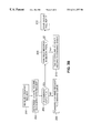
- FIGS. 3A-3C are flow charts illustrating operation of the system in accordance with strict, no-maximum, and pseudo-maximum allocation schemes.
- a computer system 10 includes at least one, and more likely several host processors or computers (hosts) 12 connected to a mass storage system 14 .
- hosts 12 may all be of the same type (i.e., same model and manufacturer). In many other applications, however, hosts 12 may be different. Thus, the manner in which each host communicates and its tolerance to changes of its protocol may differ.
- Mass storage system 14 includes a number of logical volumes 16 , each logical volume, for example, representative of one or more physical disk drive elements.
- a logical volume may represent a portion of a physical disk drive element with several of the logical volumes constituting a drive element.
- each physical drive has a number of logical volumes, for example, four, eight, or more logical volumes in a single physical disk drive element.
- Each of logical volumes 16 typically represents a relatively large amount of memory (e.g., 1 gigabyte or more).
- Logical volumes 16 together, in aggregate, define a large mass storage device having a memory capacity equal to the sum of each of the logical volumes.
- each logical volume 16 includes a corresponding command queue 17 .
- Command queues 17 represent ordered lists, each of which receives command requests sent from hosts 12 and stores the requests in records 19 . Additions to command queues 17 take place at the rear of the queue while deletions take place at the front of the queue. Thus, a request stored within the record 19 a at the front of the queue is the next one to be executed.
- Hosts 12 can send a large number of command requests which can accumulate within a command queue 17 faster than they are executed. Thus, the records in the command queue can be occupied until there are no records remaining in the queue to store newly received command requests. In this case, a “Queue Full” message is received by the host sending the command request requiring the host to re-submit the command request at a time when a record in the command queue has been freed.
- storage system 14 includes a disk drive controller 18 (e.g., that which is manufactured by EMC Corporation, Hopkinton, Mass.) interconnects host computers 12 and logical volumes 16 .
- Disk controller 18 receives memory commands, for example, read and write commands from host computers 12 over a bus 19 operating in accordance with a SCSI protocol.
- Disk controller 18 includes a processor 21 for executing computer instructions associated with the operation described below. The computer instructions are stored in a memory 23 connected to processor 21 via an internal bus 25 .
- Disk controller 18 delivers data associated with those commands to or from an appropriate one of logical volumes 16 over a second bus 20 which, for example, also operates in accordance with a SCSI protocol.
- controller 18 is also connected to a console computer 22 through a connecting bus 24 .
- Console computer 22 is used for maintenance and access to controller 18 and can be employed to set parameters of and/or to initiate maintenance commands to the controller, under user control, as is well known in the art.
- disk controller 18 on the basis of the computing environment for which the storage system is being used (i.e., type and characteristics of hosts), allows each of logical volumes 16 to increase or decrease the number of records in their respective command queues 17 from a memory pool 23 within memory 27 . For example, if a particular host 12 is tolerant in using a logical volume 16 having a command queue of varying size, disk controller 18 will select an allocation scheme which will allow the command queue to acquire a larger number of records. Generally, in this case, disk controller 18 will allow the command queue to acquire an additional record from memory pool 23 .
- disk controller 18 When the command requests stored in that record is executed, disk controller 18 allows the record to be de-allocated or returned to memory pool 23 for use by that host or another host which requires it. On the other hand, if the host is of the type which expects to use a logical volume of a fixed size, disk controller scheme will ensure that the command queue associated with that host remains unchanged.
- Each command request received by disk controller 18 generally includes information relating to 1) which particular host sent the request; 2) what path was used to receive the request; and 3) the type of host. Disk controller 18 uses this information to determine which allocation scheme will be used for a given task.
- Memory pool 23 includes a fixed number of records which are allocated by disk controller 18 among all of logical volumes 16 .
- memory pool may include a total of 2048 (800 H) records which are shared by all of the logical volumes.
- disk controller 18 selects one of three different allocation schemes for the command queue of the logical volume associated with the request. The allocation schemes will now be described.
- each logical volume is allocated with (n/m) records. For purposes of example, if there are 2048 (800 H) available queue records and 256 logical volumes, each logical volume will be assigned eight records.
- Disk controller 18 will typically use this allocation scheme when all of the hosts are of the type which are configured to expect a pre-established number of records for the command queue. Such hosts keep track of the number of command requests made to a logical volume and already know that the command queue is full and will automatically wait for an indication that a command request has been executed and a record has been freed. This strict allocation approach is also used by disk controller 18 as the default selection when the disk controller is not sure of the type or characteristics of the hosts in the computing environment.
- the Pseudo-Maximum allocation scheme is generally used when hosts of various types are connected to mass storage system 14 .
- the scheme is best suited for those arrangements in which there are hosts that are tolerant of a variable size command queue and hosts that are not.
- This approach allows the command queue for each logical volume to be assigned a number of records (r), the sum of the records for all of the command queues being greater than the total number of available queue records (n) in memory pool 23 .
- the scheme is based on the recognition that at any given point of time, the total number of command requests (the sum of all r's) sent by the hosts will almost always be less than the total number of available queue records (n).
- a command queue associated with a particular logical volume may require a large number of records while, at the same time, another command queue associated with a different logical volume will require a far fewer number of records.
- disk controller 18 simply informs the particular host making a request that the queue is full. Because the host is of the type tolerant of being told that the queue is full, it can simply re-submit its requests after a predetermined time.
- the No-Maximum allocation scheme is used when all of the hosts are tolerant of a variable size command queue. In this case, each host can freely allocate further records from memory pool 23 as needed. As was the case, in the Pseudo-Maximum approach, if memory pool 23 is depleted, the requesting host simply issues a message to the host indicating that the particular command queue is full.
- FIGS. 3A-3C flowcharts representing the operation of disk controller 18 for the Strict, Pseudo-Maximum, and No-Maximum allocation schemes are shown, respectively.
- disk controller 18 determines which logical volume 16 the request is associated with ( 102 ) and whether the command queue associated with that logical volume is full ( 104 ). If the command queue is not full, disk controller 18 simply forwards the command request where it is buffered within the command queue ( 106 ). If the command queue is full, disk controller 18 issues a “Queue Full” message to the host sending the command request so that the host can re-submit the command request at a time when a record in the command queue has been freed ( 108 ).
- disk controller 18 determines which logical volume 16 the request is associated with ( 202 ) and whether the command queue associated with that logical volume is full ( 204 ). If the command queue is not full, disk controller simply forwards the command request where it is buffered within the command queue ( 206 ). If the command queue is full, disk controller 18 determines whether there are available records in memory pool 23 which can be allocated to the command queue ( 208 ). If available queue records are available, disk controller 18 tags the record to indicate which logical volume is using the record and that it is no longer available for use, until de-allocated ( 210 ).
- Disk controller 18 then allocates a record to the command queue. If available queue records are not available from memory pool 23 , disk controller issues a “Queue Full” message to the host which sent the command request so that the host can re-submit the command request at a time when a record in the command queue has been freed ( 214 ).
- disk controller 18 determines which logical volume 16 the request is associated with ( 302 ) and whether the command queue associated with that logical volume is full ( 304 ). If the command queue is not full, disk controller simply forwards the command request where it is buffered within the command queue ( 306 ). If the command queue is full, disk controller 18 determines whether the requesting host is one that can tolerate a variable length command queue ( 308 ).
- disk controller 18 issues a “Queue Full” message to the host sending the command request so that the host can re-submit the command request at a time when a record in the command queue has been freed ( 310 ).
- disk controller 18 determines whether there are available records in memory pool 23 which can be allocated to the command queue ( 312 ). If available queue records are available, disk controller 18 tags the record to indicate which logical volume is using the record and that it is no longer available for use, until de-allocated ( 314 ). Disk controller 18 then allocates a record to the command queue ( 316 ). If available queue records are not available from memory pool 23 , disk controller issues the “Queue Full” message to the host, which sent the command request ( 318 ).
Abstract
Description
Claims (21)
Priority Applications (1)
| Application Number | Priority Date | Filing Date | Title |
|---|---|---|---|
| US09/290,844 US6311257B1 (en) | 1999-04-13 | 1999-04-13 | Method and system for allocating memory for a command queue |
Applications Claiming Priority (1)
| Application Number | Priority Date | Filing Date | Title |
|---|---|---|---|
| US09/290,844 US6311257B1 (en) | 1999-04-13 | 1999-04-13 | Method and system for allocating memory for a command queue |
Publications (1)
| Publication Number | Publication Date |
|---|---|
| US6311257B1 true US6311257B1 (en) | 2001-10-30 |
Family
ID=23117783
Family Applications (1)
| Application Number | Title | Priority Date | Filing Date |
|---|---|---|---|
| US09/290,844 Expired - Lifetime US6311257B1 (en) | 1999-04-13 | 1999-04-13 | Method and system for allocating memory for a command queue |
Country Status (1)
| Country | Link |
|---|---|
| US (1) | US6311257B1 (en) |
Cited By (19)
| Publication number | Priority date | Publication date | Assignee | Title |
|---|---|---|---|---|
| US6694410B1 (en) | 2001-04-30 | 2004-02-17 | Lsi Logic Corporation | Method and apparatus for loading/storing multiple data sources to common memory unit |
| US6735677B1 (en) * | 2001-04-30 | 2004-05-11 | Lsi Logic Corporation | Parameterizable queued memory access system |
| US20050102469A1 (en) * | 2003-11-12 | 2005-05-12 | Ofir Zohar | Distributed task queues in a multiple-port storage system |
| US7076604B1 (en) * | 2002-12-24 | 2006-07-11 | Western Digital Technologies, Inc. | Disk drive employing a disk command data structure for tracking a write verify status of a write command |
| EP1862893A2 (en) * | 2006-05-31 | 2007-12-05 | Hitachi, Ltd. | Storage control apparatus and method for controlling number of commands executed in storage control apparatus |
| EP1936487A2 (en) * | 2006-11-28 | 2008-06-25 | Hitachi, Ltd. | Storage subsystem and remote copy system using said subsystem |
| US20090198748A1 (en) * | 2008-02-06 | 2009-08-06 | Kevin John Ash | Apparatus, system, and method for relocating storage pool hot spots |
| US20090198940A1 (en) * | 2008-02-06 | 2009-08-06 | Kevin John Ash | Apparatus, system, and method for relocating logical array hot spots |
| US20090307341A1 (en) * | 2008-06-04 | 2009-12-10 | Hitachi, Ltd. | Method for managing storage system |
| US20090319743A1 (en) * | 2008-06-23 | 2009-12-24 | Kevin John Ash | Apparatus, system, and method for migrating wear spots |
| US20100287310A1 (en) * | 2009-05-08 | 2010-11-11 | Won-Seok Jung | Method and controller for processing commands in a storage device |
| WO2013098888A1 (en) * | 2011-12-27 | 2013-07-04 | Hitachi, Ltd. | Storage apparatus and method for controlling same |
| US8868876B2 (en) | 2011-12-28 | 2014-10-21 | International Business Machines Corporation | Dedicated large page memory pools |
| US20150331710A1 (en) * | 2014-05-13 | 2015-11-19 | International Business Machines Corporation | Using queues corresponding to attribute values associated with units of work to select the units of work to process |
| US9201778B2 (en) * | 2005-08-25 | 2015-12-01 | Lattice Semiconductor Corporation | Smart scalable storage switch architecture |
| US20170031592A1 (en) * | 2015-07-29 | 2017-02-02 | Sandisk Technologies Inc. | Data storage device with command buffer management module and method of operating same |
| CN107562369A (en) * | 2016-06-30 | 2018-01-09 | 爱思开海力士有限公司 | Memory Controller, storage buffer chip and storage system |
| US10331584B2 (en) * | 2017-03-09 | 2019-06-25 | Toshiba Memory Corporation | Internal system namespace exposed through use of two local processors and controller memory buffer with two reserved areas |
| US20220342601A1 (en) * | 2021-04-27 | 2022-10-27 | Samsung Electronics Co., Ltd. | Systems, methods, and devices for adaptive near storage computation |
Citations (5)
| Publication number | Priority date | Publication date | Assignee | Title |
|---|---|---|---|---|
| US5561785A (en) * | 1992-10-29 | 1996-10-01 | International Business Machines Corporation | System for allocating and returning storage and collecting garbage using subpool of available blocks |
| US5651111A (en) * | 1994-06-07 | 1997-07-22 | Digital Equipment Corporation | Method and apparatus for producing a software test system using complementary code to resolve external dependencies |
| US5796413A (en) * | 1995-12-06 | 1998-08-18 | Compaq Computer Corporation | Graphics controller utilizing video memory to provide macro command capability and enhanched command buffering |
| US6000011A (en) * | 1996-12-09 | 1999-12-07 | International Business Machines Corporation | Multi-entry fully associative transition cache |
| US6141707A (en) * | 1998-05-28 | 2000-10-31 | Emc Corporation | Input/output request allocation by establishing master command queue among plurality of command queues to receive and store commands, determine logical volume, and forwarding command to determined logical volume |
-
1999
- 1999-04-13 US US09/290,844 patent/US6311257B1/en not_active Expired - Lifetime
Patent Citations (5)
| Publication number | Priority date | Publication date | Assignee | Title |
|---|---|---|---|---|
| US5561785A (en) * | 1992-10-29 | 1996-10-01 | International Business Machines Corporation | System for allocating and returning storage and collecting garbage using subpool of available blocks |
| US5651111A (en) * | 1994-06-07 | 1997-07-22 | Digital Equipment Corporation | Method and apparatus for producing a software test system using complementary code to resolve external dependencies |
| US5796413A (en) * | 1995-12-06 | 1998-08-18 | Compaq Computer Corporation | Graphics controller utilizing video memory to provide macro command capability and enhanched command buffering |
| US6000011A (en) * | 1996-12-09 | 1999-12-07 | International Business Machines Corporation | Multi-entry fully associative transition cache |
| US6141707A (en) * | 1998-05-28 | 2000-10-31 | Emc Corporation | Input/output request allocation by establishing master command queue among plurality of command queues to receive and store commands, determine logical volume, and forwarding command to determined logical volume |
Cited By (38)
| Publication number | Priority date | Publication date | Assignee | Title |
|---|---|---|---|---|
| US6694410B1 (en) | 2001-04-30 | 2004-02-17 | Lsi Logic Corporation | Method and apparatus for loading/storing multiple data sources to common memory unit |
| US6735677B1 (en) * | 2001-04-30 | 2004-05-11 | Lsi Logic Corporation | Parameterizable queued memory access system |
| US7076604B1 (en) * | 2002-12-24 | 2006-07-11 | Western Digital Technologies, Inc. | Disk drive employing a disk command data structure for tracking a write verify status of a write command |
| US7120737B1 (en) | 2002-12-24 | 2006-10-10 | Western Digital Technologies, Inc. | Disk drive employing a disk command data structure for tracking a write verify status of a write command |
| US20050102469A1 (en) * | 2003-11-12 | 2005-05-12 | Ofir Zohar | Distributed task queues in a multiple-port storage system |
| US7870334B2 (en) * | 2003-11-12 | 2011-01-11 | International Business Machines Corporation | Distributed task queues in a multiple-port storage system |
| US9201778B2 (en) * | 2005-08-25 | 2015-12-01 | Lattice Semiconductor Corporation | Smart scalable storage switch architecture |
| EP1862893A2 (en) * | 2006-05-31 | 2007-12-05 | Hitachi, Ltd. | Storage control apparatus and method for controlling number of commands executed in storage control apparatus |
| US20080005490A1 (en) * | 2006-05-31 | 2008-01-03 | Shinjiro Shiraki | Storage control apparatus and method for controlling number of commands executed in storage control apparatus |
| EP1862893A3 (en) * | 2006-05-31 | 2009-11-18 | Hitachi, Ltd. | Storage control apparatus and method for controlling the number of commands executed in storage control apparatus |
| US7685342B2 (en) * | 2006-05-31 | 2010-03-23 | Hitachi, Ltd. | Storage control apparatus and method for controlling number of commands executed in storage control apparatus |
| EP1936487A3 (en) * | 2006-11-28 | 2010-08-25 | Hitachi, Ltd. | Storage subsystem and remote copy system using said subsystem |
| EP1936487A2 (en) * | 2006-11-28 | 2008-06-25 | Hitachi, Ltd. | Storage subsystem and remote copy system using said subsystem |
| US8108562B2 (en) | 2006-11-28 | 2012-01-31 | Hitachi, Ltd. | Storage subsystem and remote copy system using said subsystem |
| US20100077106A1 (en) * | 2006-11-28 | 2010-03-25 | Hitachi, Ltd. | Storage subsystem and remote copy system using said subsystem |
| US20090198940A1 (en) * | 2008-02-06 | 2009-08-06 | Kevin John Ash | Apparatus, system, and method for relocating logical array hot spots |
| US20090198748A1 (en) * | 2008-02-06 | 2009-08-06 | Kevin John Ash | Apparatus, system, and method for relocating storage pool hot spots |
| US8914340B2 (en) | 2008-02-06 | 2014-12-16 | International Business Machines Corporation | Apparatus, system, and method for relocating storage pool hot spots |
| US8423739B2 (en) * | 2008-02-06 | 2013-04-16 | International Business Machines Corporation | Apparatus, system, and method for relocating logical array hot spots |
| US8683025B2 (en) * | 2008-06-04 | 2014-03-25 | Hitachi, Ltd. | Method for managing storage system |
| US20090307341A1 (en) * | 2008-06-04 | 2009-12-10 | Hitachi, Ltd. | Method for managing storage system |
| US20090319743A1 (en) * | 2008-06-23 | 2009-12-24 | Kevin John Ash | Apparatus, system, and method for migrating wear spots |
| US8055835B2 (en) | 2008-06-23 | 2011-11-08 | International Business Machines Corporation | Apparatus, system, and method for migrating wear spots |
| US8266330B2 (en) * | 2009-05-08 | 2012-09-11 | Samsung Electronics Co., Ltd. | Method and controller for processing commands in a storage device |
| US20100287310A1 (en) * | 2009-05-08 | 2010-11-11 | Won-Seok Jung | Method and controller for processing commands in a storage device |
| KR20100121340A (en) * | 2009-05-08 | 2010-11-17 | 삼성전자주식회사 | Method for processing command of non-volatile storage device interfacing with host using serial interface protocol |
| KR101662729B1 (en) * | 2009-05-08 | 2016-10-06 | 삼성전자주식회사 | Method for processing command of non-volatile storage device interfacing with host using serial interface protocol and Memory controller for performing the method |
| WO2013098888A1 (en) * | 2011-12-27 | 2013-07-04 | Hitachi, Ltd. | Storage apparatus and method for controlling same |
| US8868876B2 (en) | 2011-12-28 | 2014-10-21 | International Business Machines Corporation | Dedicated large page memory pools |
| US9921879B2 (en) * | 2014-05-13 | 2018-03-20 | International Business Machines Corporation | Using queues corresponding to attribute values associated with units of work to select the units of work to process |
| US20150331710A1 (en) * | 2014-05-13 | 2015-11-19 | International Business Machines Corporation | Using queues corresponding to attribute values associated with units of work to select the units of work to process |
| US20170031592A1 (en) * | 2015-07-29 | 2017-02-02 | Sandisk Technologies Inc. | Data storage device with command buffer management module and method of operating same |
| US10013173B2 (en) * | 2015-07-29 | 2018-07-03 | Sandisk Technologies Llc | Data storage device with command buffer management module and method of operating same |
| CN107562369A (en) * | 2016-06-30 | 2018-01-09 | 爱思开海力士有限公司 | Memory Controller, storage buffer chip and storage system |
| CN107562369B (en) * | 2016-06-30 | 2020-08-07 | 爱思开海力士有限公司 | Memory controller, memory buffer chip and memory system |
| US10990322B2 (en) | 2016-06-30 | 2021-04-27 | SK Hynix Inc. | Memory buffer chip, memory system and method of controlling the memory buffer chip |
| US10331584B2 (en) * | 2017-03-09 | 2019-06-25 | Toshiba Memory Corporation | Internal system namespace exposed through use of two local processors and controller memory buffer with two reserved areas |
| US20220342601A1 (en) * | 2021-04-27 | 2022-10-27 | Samsung Electronics Co., Ltd. | Systems, methods, and devices for adaptive near storage computation |
Similar Documents
| Publication | Publication Date | Title |
|---|---|---|
| US6311257B1 (en) | Method and system for allocating memory for a command queue | |
| US11221975B2 (en) | Management of shared resources in a software-defined storage environment | |
| US8838851B2 (en) | Techniques for path selection | |
| US6141707A (en) | Input/output request allocation by establishing master command queue among plurality of command queues to receive and store commands, determine logical volume, and forwarding command to determined logical volume | |
| US8793443B2 (en) | Methods and structure for improved buffer allocation in a storage controller | |
| US6094605A (en) | Virtual automated cartridge system | |
| US7363629B2 (en) | Method, system, and program for remote resource management | |
| US20050097384A1 (en) | Data processing system with fabric for sharing an I/O device between logical partitions | |
| JP4452064B2 (en) | Information processing system, information processing apparatus, information processing apparatus control method, and program | |
| EP2687991A2 (en) | Methods And Structure For Improved Flexibility In Shared Storage Caching By Multiple Systems Operating As Multiple Virtual Machines | |
| US20080059752A1 (en) | Virtualization system and region allocation control method | |
| EP2302500A2 (en) | Application and tier configuration management in dynamic page realloction storage system | |
| US8145930B2 (en) | Storage system and management information acquisition method for power saving | |
| JP2001290746A (en) | Method for giving priority to i/o request | |
| US8694563B1 (en) | Space recovery for thin-provisioned storage volumes | |
| JP2012523624A (en) | Method and apparatus for storing data in a flash memory data storage device | |
| US6343351B1 (en) | Method and system for the dynamic scheduling of requests to access a storage system | |
| JP4176341B2 (en) | Storage controller | |
| US7032093B1 (en) | On-demand allocation of physical storage for virtual volumes using a zero logical disk | |
| WO2013042174A1 (en) | Computer system and storage management method | |
| US8954666B2 (en) | Storage subsystem | |
| JPH08263429A (en) | Bus access arbitration system and method for recognition of bus access | |
| US9201598B2 (en) | Apparatus and method for sharing resources between storage devices | |
| US20050108235A1 (en) | Information processing system and method | |
| JP2019191886A (en) | Information processing apparatus, information processing method, and program |
Legal Events
| Date | Code | Title | Description |
|---|---|---|---|
| AS | Assignment |
Owner name: EMC CORPORATION, MASSACHUSETTS Free format text: ASSIGNMENT OF ASSIGNORS INTEREST;ASSIGNORS:FITZGERALD, JOHN T.;OFER, EREZ;HALLIGAN, KENNETH;REEL/FRAME:009899/0146;SIGNING DATES FROM 19990330 TO 19990331 |
|
| STCF | Information on status: patent grant |
Free format text: PATENTED CASE |
|
| FEPP | Fee payment procedure |
Free format text: PAYOR NUMBER ASSIGNED (ORIGINAL EVENT CODE: ASPN); ENTITY STATUS OF PATENT OWNER: LARGE ENTITY |
|
| FPAY | Fee payment |
Year of fee payment: 4 |
|
| FPAY | Fee payment |
Year of fee payment: 8 |
|
| FEPP | Fee payment procedure |
Free format text: PAYOR NUMBER ASSIGNED (ORIGINAL EVENT CODE: ASPN); ENTITY STATUS OF PATENT OWNER: LARGE ENTITY Free format text: PAYER NUMBER DE-ASSIGNED (ORIGINAL EVENT CODE: RMPN); ENTITY STATUS OF PATENT OWNER: LARGE ENTITY |
|
| FPAY | Fee payment |
Year of fee payment: 12 |
|
| AS | Assignment |
Owner name: THE BANK OF NEW YORK MELLON TRUST COMPANY, N.A., AS NOTES COLLATERAL AGENT, TEXAS Free format text: SECURITY AGREEMENT;ASSIGNORS:ASAP SOFTWARE EXPRESS, INC.;AVENTAIL LLC;CREDANT TECHNOLOGIES, INC.;AND OTHERS;REEL/FRAME:040136/0001 Effective date: 20160907 Owner name: CREDIT SUISSE AG, CAYMAN ISLANDS BRANCH, AS COLLATERAL AGENT, NORTH CAROLINA Free format text: SECURITY AGREEMENT;ASSIGNORS:ASAP SOFTWARE EXPRESS, INC.;AVENTAIL LLC;CREDANT TECHNOLOGIES, INC.;AND OTHERS;REEL/FRAME:040134/0001 Effective date: 20160907 Owner name: CREDIT SUISSE AG, CAYMAN ISLANDS BRANCH, AS COLLAT Free format text: SECURITY AGREEMENT;ASSIGNORS:ASAP SOFTWARE EXPRESS, INC.;AVENTAIL LLC;CREDANT TECHNOLOGIES, INC.;AND OTHERS;REEL/FRAME:040134/0001 Effective date: 20160907 Owner name: THE BANK OF NEW YORK MELLON TRUST COMPANY, N.A., A Free format text: SECURITY AGREEMENT;ASSIGNORS:ASAP SOFTWARE EXPRESS, INC.;AVENTAIL LLC;CREDANT TECHNOLOGIES, INC.;AND OTHERS;REEL/FRAME:040136/0001 Effective date: 20160907 |
|
| AS | Assignment |
Owner name: EMC IP HOLDING COMPANY LLC, MASSACHUSETTS Free format text: ASSIGNMENT OF ASSIGNORS INTEREST;ASSIGNOR:EMC CORPORATION;REEL/FRAME:040203/0001 Effective date: 20160906 |
|
| AS | Assignment |
Owner name: THE BANK OF NEW YORK MELLON TRUST COMPANY, N.A., T Free format text: SECURITY AGREEMENT;ASSIGNORS:CREDANT TECHNOLOGIES, INC.;DELL INTERNATIONAL L.L.C.;DELL MARKETING L.P.;AND OTHERS;REEL/FRAME:049452/0223 Effective date: 20190320 Owner name: THE BANK OF NEW YORK MELLON TRUST COMPANY, N.A., TEXAS Free format text: SECURITY AGREEMENT;ASSIGNORS:CREDANT TECHNOLOGIES, INC.;DELL INTERNATIONAL L.L.C.;DELL MARKETING L.P.;AND OTHERS;REEL/FRAME:049452/0223 Effective date: 20190320 |
|
| AS | Assignment |
Owner name: WYSE TECHNOLOGY L.L.C., CALIFORNIA Free format text: RELEASE BY SECURED PARTY;ASSIGNOR:CREDIT SUISSE AG, CAYMAN ISLANDS BRANCH;REEL/FRAME:058216/0001 Effective date: 20211101 Owner name: SCALEIO LLC, MASSACHUSETTS Free format text: RELEASE BY SECURED PARTY;ASSIGNOR:CREDIT SUISSE AG, CAYMAN ISLANDS BRANCH;REEL/FRAME:058216/0001 Effective date: 20211101 Owner name: MOZY, INC., WASHINGTON Free format text: RELEASE BY SECURED PARTY;ASSIGNOR:CREDIT SUISSE AG, CAYMAN ISLANDS BRANCH;REEL/FRAME:058216/0001 Effective date: 20211101 Owner name: MAGINATICS LLC, CALIFORNIA Free format text: RELEASE BY SECURED PARTY;ASSIGNOR:CREDIT SUISSE AG, CAYMAN ISLANDS BRANCH;REEL/FRAME:058216/0001 Effective date: 20211101 Owner name: FORCE10 NETWORKS, INC., CALIFORNIA Free format text: RELEASE BY SECURED PARTY;ASSIGNOR:CREDIT SUISSE AG, CAYMAN ISLANDS BRANCH;REEL/FRAME:058216/0001 Effective date: 20211101 Owner name: EMC IP HOLDING COMPANY LLC, TEXAS Free format text: RELEASE BY SECURED PARTY;ASSIGNOR:CREDIT SUISSE AG, CAYMAN ISLANDS BRANCH;REEL/FRAME:058216/0001 Effective date: 20211101 Owner name: EMC CORPORATION, MASSACHUSETTS Free format text: RELEASE BY SECURED PARTY;ASSIGNOR:CREDIT SUISSE AG, CAYMAN ISLANDS BRANCH;REEL/FRAME:058216/0001 Effective date: 20211101 Owner name: DELL SYSTEMS CORPORATION, TEXAS Free format text: RELEASE BY SECURED PARTY;ASSIGNOR:CREDIT SUISSE AG, CAYMAN ISLANDS BRANCH;REEL/FRAME:058216/0001 Effective date: 20211101 Owner name: DELL SOFTWARE INC., CALIFORNIA Free format text: RELEASE BY SECURED PARTY;ASSIGNOR:CREDIT SUISSE AG, CAYMAN ISLANDS BRANCH;REEL/FRAME:058216/0001 Effective date: 20211101 Owner name: DELL PRODUCTS L.P., TEXAS Free format text: RELEASE BY SECURED PARTY;ASSIGNOR:CREDIT SUISSE AG, CAYMAN ISLANDS BRANCH;REEL/FRAME:058216/0001 Effective date: 20211101 Owner name: DELL MARKETING L.P., TEXAS Free format text: RELEASE BY SECURED PARTY;ASSIGNOR:CREDIT SUISSE AG, CAYMAN ISLANDS BRANCH;REEL/FRAME:058216/0001 Effective date: 20211101 Owner name: DELL INTERNATIONAL, L.L.C., TEXAS Free format text: RELEASE BY SECURED PARTY;ASSIGNOR:CREDIT SUISSE AG, CAYMAN ISLANDS BRANCH;REEL/FRAME:058216/0001 Effective date: 20211101 Owner name: DELL USA L.P., TEXAS Free format text: RELEASE BY SECURED PARTY;ASSIGNOR:CREDIT SUISSE AG, CAYMAN ISLANDS BRANCH;REEL/FRAME:058216/0001 Effective date: 20211101 Owner name: CREDANT TECHNOLOGIES, INC., TEXAS Free format text: RELEASE BY SECURED PARTY;ASSIGNOR:CREDIT SUISSE AG, CAYMAN ISLANDS BRANCH;REEL/FRAME:058216/0001 Effective date: 20211101 Owner name: AVENTAIL LLC, CALIFORNIA Free format text: RELEASE BY SECURED PARTY;ASSIGNOR:CREDIT SUISSE AG, CAYMAN ISLANDS BRANCH;REEL/FRAME:058216/0001 Effective date: 20211101 Owner name: ASAP SOFTWARE EXPRESS, INC., ILLINOIS Free format text: RELEASE BY SECURED PARTY;ASSIGNOR:CREDIT SUISSE AG, CAYMAN ISLANDS BRANCH;REEL/FRAME:058216/0001 Effective date: 20211101 |
|
| AS | Assignment |
Owner name: SCALEIO LLC, MASSACHUSETTS Free format text: RELEASE OF SECURITY INTEREST IN PATENTS PREVIOUSLY RECORDED AT REEL/FRAME (040136/0001);ASSIGNOR:THE BANK OF NEW YORK MELLON TRUST COMPANY, N.A., AS NOTES COLLATERAL AGENT;REEL/FRAME:061324/0001 Effective date: 20220329 Owner name: EMC IP HOLDING COMPANY LLC (ON BEHALF OF ITSELF AND AS SUCCESSOR-IN-INTEREST TO MOZY, INC.), TEXAS Free format text: RELEASE OF SECURITY INTEREST IN PATENTS PREVIOUSLY RECORDED AT REEL/FRAME (040136/0001);ASSIGNOR:THE BANK OF NEW YORK MELLON TRUST COMPANY, N.A., AS NOTES COLLATERAL AGENT;REEL/FRAME:061324/0001 Effective date: 20220329 Owner name: EMC CORPORATION (ON BEHALF OF ITSELF AND AS SUCCESSOR-IN-INTEREST TO MAGINATICS LLC), MASSACHUSETTS Free format text: RELEASE OF SECURITY INTEREST IN PATENTS PREVIOUSLY RECORDED AT REEL/FRAME (040136/0001);ASSIGNOR:THE BANK OF NEW YORK MELLON TRUST COMPANY, N.A., AS NOTES COLLATERAL AGENT;REEL/FRAME:061324/0001 Effective date: 20220329 Owner name: DELL MARKETING CORPORATION (SUCCESSOR-IN-INTEREST TO FORCE10 NETWORKS, INC. AND WYSE TECHNOLOGY L.L.C.), TEXAS Free format text: RELEASE OF SECURITY INTEREST IN PATENTS PREVIOUSLY RECORDED AT REEL/FRAME (040136/0001);ASSIGNOR:THE BANK OF NEW YORK MELLON TRUST COMPANY, N.A., AS NOTES COLLATERAL AGENT;REEL/FRAME:061324/0001 Effective date: 20220329 Owner name: DELL PRODUCTS L.P., TEXAS Free format text: RELEASE OF SECURITY INTEREST IN PATENTS PREVIOUSLY RECORDED AT REEL/FRAME (040136/0001);ASSIGNOR:THE BANK OF NEW YORK MELLON TRUST COMPANY, N.A., AS NOTES COLLATERAL AGENT;REEL/FRAME:061324/0001 Effective date: 20220329 Owner name: DELL INTERNATIONAL L.L.C., TEXAS Free format text: RELEASE OF SECURITY INTEREST IN PATENTS PREVIOUSLY RECORDED AT REEL/FRAME (040136/0001);ASSIGNOR:THE BANK OF NEW YORK MELLON TRUST COMPANY, N.A., AS NOTES COLLATERAL AGENT;REEL/FRAME:061324/0001 Effective date: 20220329 Owner name: DELL USA L.P., TEXAS Free format text: RELEASE OF SECURITY INTEREST IN PATENTS PREVIOUSLY RECORDED AT REEL/FRAME (040136/0001);ASSIGNOR:THE BANK OF NEW YORK MELLON TRUST COMPANY, N.A., AS NOTES COLLATERAL AGENT;REEL/FRAME:061324/0001 Effective date: 20220329 Owner name: DELL MARKETING L.P. (ON BEHALF OF ITSELF AND AS SUCCESSOR-IN-INTEREST TO CREDANT TECHNOLOGIES, INC.), TEXAS Free format text: RELEASE OF SECURITY INTEREST IN PATENTS PREVIOUSLY RECORDED AT REEL/FRAME (040136/0001);ASSIGNOR:THE BANK OF NEW YORK MELLON TRUST COMPANY, N.A., AS NOTES COLLATERAL AGENT;REEL/FRAME:061324/0001 Effective date: 20220329 Owner name: DELL MARKETING CORPORATION (SUCCESSOR-IN-INTEREST TO ASAP SOFTWARE EXPRESS, INC.), TEXAS Free format text: RELEASE OF SECURITY INTEREST IN PATENTS PREVIOUSLY RECORDED AT REEL/FRAME (040136/0001);ASSIGNOR:THE BANK OF NEW YORK MELLON TRUST COMPANY, N.A., AS NOTES COLLATERAL AGENT;REEL/FRAME:061324/0001 Effective date: 20220329 |
|
| AS | Assignment |
Owner name: SCALEIO LLC, MASSACHUSETTS Free format text: RELEASE OF SECURITY INTEREST IN PATENTS PREVIOUSLY RECORDED AT REEL/FRAME (045455/0001);ASSIGNOR:THE BANK OF NEW YORK MELLON TRUST COMPANY, N.A., AS NOTES COLLATERAL AGENT;REEL/FRAME:061753/0001 Effective date: 20220329 Owner name: EMC IP HOLDING COMPANY LLC (ON BEHALF OF ITSELF AND AS SUCCESSOR-IN-INTEREST TO MOZY, INC.), TEXAS Free format text: RELEASE OF SECURITY INTEREST IN PATENTS PREVIOUSLY RECORDED AT REEL/FRAME (045455/0001);ASSIGNOR:THE BANK OF NEW YORK MELLON TRUST COMPANY, N.A., AS NOTES COLLATERAL AGENT;REEL/FRAME:061753/0001 Effective date: 20220329 Owner name: EMC CORPORATION (ON BEHALF OF ITSELF AND AS SUCCESSOR-IN-INTEREST TO MAGINATICS LLC), MASSACHUSETTS Free format text: RELEASE OF SECURITY INTEREST IN PATENTS PREVIOUSLY RECORDED AT REEL/FRAME (045455/0001);ASSIGNOR:THE BANK OF NEW YORK MELLON TRUST COMPANY, N.A., AS NOTES COLLATERAL AGENT;REEL/FRAME:061753/0001 Effective date: 20220329 Owner name: DELL MARKETING CORPORATION (SUCCESSOR-IN-INTEREST TO FORCE10 NETWORKS, INC. AND WYSE TECHNOLOGY L.L.C.), TEXAS Free format text: RELEASE OF SECURITY INTEREST IN PATENTS PREVIOUSLY RECORDED AT REEL/FRAME (045455/0001);ASSIGNOR:THE BANK OF NEW YORK MELLON TRUST COMPANY, N.A., AS NOTES COLLATERAL AGENT;REEL/FRAME:061753/0001 Effective date: 20220329 Owner name: DELL PRODUCTS L.P., TEXAS Free format text: RELEASE OF SECURITY INTEREST IN PATENTS PREVIOUSLY RECORDED AT REEL/FRAME (045455/0001);ASSIGNOR:THE BANK OF NEW YORK MELLON TRUST COMPANY, N.A., AS NOTES COLLATERAL AGENT;REEL/FRAME:061753/0001 Effective date: 20220329 Owner name: DELL INTERNATIONAL L.L.C., TEXAS Free format text: RELEASE OF SECURITY INTEREST IN PATENTS PREVIOUSLY RECORDED AT REEL/FRAME (045455/0001);ASSIGNOR:THE BANK OF NEW YORK MELLON TRUST COMPANY, N.A., AS NOTES COLLATERAL AGENT;REEL/FRAME:061753/0001 Effective date: 20220329 Owner name: DELL USA L.P., TEXAS Free format text: RELEASE OF SECURITY INTEREST IN PATENTS PREVIOUSLY RECORDED AT REEL/FRAME (045455/0001);ASSIGNOR:THE BANK OF NEW YORK MELLON TRUST COMPANY, N.A., AS NOTES COLLATERAL AGENT;REEL/FRAME:061753/0001 Effective date: 20220329 Owner name: DELL MARKETING L.P. (ON BEHALF OF ITSELF AND AS SUCCESSOR-IN-INTEREST TO CREDANT TECHNOLOGIES, INC.), TEXAS Free format text: RELEASE OF SECURITY INTEREST IN PATENTS PREVIOUSLY RECORDED AT REEL/FRAME (045455/0001);ASSIGNOR:THE BANK OF NEW YORK MELLON TRUST COMPANY, N.A., AS NOTES COLLATERAL AGENT;REEL/FRAME:061753/0001 Effective date: 20220329 Owner name: DELL MARKETING CORPORATION (SUCCESSOR-IN-INTEREST TO ASAP SOFTWARE EXPRESS, INC.), TEXAS Free format text: RELEASE OF SECURITY INTEREST IN PATENTS PREVIOUSLY RECORDED AT REEL/FRAME (045455/0001);ASSIGNOR:THE BANK OF NEW YORK MELLON TRUST COMPANY, N.A., AS NOTES COLLATERAL AGENT;REEL/FRAME:061753/0001 Effective date: 20220329 |