US6307604B1 - Light source having a luminescent layer - Google Patents
Light source having a luminescent layer Download PDFInfo
- Publication number
- US6307604B1 US6307604B1 US08/382,937 US38293795A US6307604B1 US 6307604 B1 US6307604 B1 US 6307604B1 US 38293795 A US38293795 A US 38293795A US 6307604 B1 US6307604 B1 US 6307604B1
- Authority
- US
- United States
- Prior art keywords
- light
- cholesteric
- luminescent
- wavelength range
- layer
- Prior art date
- Legal status (The legal status is an assumption and is not a legal conclusion. Google has not performed a legal analysis and makes no representation as to the accuracy of the status listed.)
- Expired - Lifetime
Links
- 230000003098 cholesteric effect Effects 0.000 claims abstract description 63
- 239000013078 crystal Substances 0.000 claims abstract description 9
- 239000000758 substrate Substances 0.000 claims description 9
- 230000010287 polarization Effects 0.000 claims description 6
- 239000003086 colorant Substances 0.000 claims description 5
- 239000011159 matrix material Substances 0.000 claims description 5
- 238000001914 filtration Methods 0.000 claims 2
- 230000004936 stimulating effect Effects 0.000 claims 2
- 230000003287 optical effect Effects 0.000 abstract description 4
- 230000005855 radiation Effects 0.000 description 17
- 238000010521 absorption reaction Methods 0.000 description 3
- 230000000694 effects Effects 0.000 description 3
- 238000000034 method Methods 0.000 description 3
- 239000012141 concentrate Substances 0.000 description 2
- 230000001419 dependent effect Effects 0.000 description 2
- 238000004519 manufacturing process Methods 0.000 description 2
- 239000000463 material Substances 0.000 description 2
- 238000001228 spectrum Methods 0.000 description 2
- 230000003190 augmentative effect Effects 0.000 description 1
- 238000005136 cathodoluminescence Methods 0.000 description 1
- 238000004020 luminiscence type Methods 0.000 description 1
- 238000012986 modification Methods 0.000 description 1
- 230000004048 modification Effects 0.000 description 1
- 230000000704 physical effect Effects 0.000 description 1
Images
Classifications
-
- G—PHYSICS
- G02—OPTICS
- G02F—OPTICAL DEVICES OR ARRANGEMENTS FOR THE CONTROL OF LIGHT BY MODIFICATION OF THE OPTICAL PROPERTIES OF THE MEDIA OF THE ELEMENTS INVOLVED THEREIN; NON-LINEAR OPTICS; FREQUENCY-CHANGING OF LIGHT; OPTICAL LOGIC ELEMENTS; OPTICAL ANALOGUE/DIGITAL CONVERTERS
- G02F1/00—Devices or arrangements for the control of the intensity, colour, phase, polarisation or direction of light arriving from an independent light source, e.g. switching, gating or modulating; Non-linear optics
- G02F1/01—Devices or arrangements for the control of the intensity, colour, phase, polarisation or direction of light arriving from an independent light source, e.g. switching, gating or modulating; Non-linear optics for the control of the intensity, phase, polarisation or colour
- G02F1/13—Devices or arrangements for the control of the intensity, colour, phase, polarisation or direction of light arriving from an independent light source, e.g. switching, gating or modulating; Non-linear optics for the control of the intensity, phase, polarisation or colour based on liquid crystals, e.g. single liquid crystal display cells
- G02F1/133—Constructional arrangements; Operation of liquid crystal cells; Circuit arrangements
- G02F1/1333—Constructional arrangements; Manufacturing methods
- G02F1/1335—Structural association of cells with optical devices, e.g. polarisers or reflectors
- G02F1/1336—Illuminating devices
- G02F1/133617—Illumination with ultraviolet light; Luminescent elements or materials associated to the cell
-
- H—ELECTRICITY
- H01—ELECTRIC ELEMENTS
- H01J—ELECTRIC DISCHARGE TUBES OR DISCHARGE LAMPS
- H01J63/00—Cathode-ray or electron-stream lamps
- H01J63/02—Details, e.g. electrode, gas filling, shape of vessel
- H01J63/04—Vessels provided with luminescent coatings; Selection of materials for the coatings
-
- H—ELECTRICITY
- H04—ELECTRIC COMMUNICATION TECHNIQUE
- H04N—PICTORIAL COMMUNICATION, e.g. TELEVISION
- H04N9/00—Details of colour television systems
- H04N9/12—Picture reproducers
- H04N9/31—Projection devices for colour picture display, e.g. using electronic spatial light modulators [ESLM]
- H04N9/3141—Constructional details thereof
- H04N9/315—Modulator illumination systems
- H04N9/3167—Modulator illumination systems for polarizing the light beam
-
- G—PHYSICS
- G02—OPTICS
- G02F—OPTICAL DEVICES OR ARRANGEMENTS FOR THE CONTROL OF LIGHT BY MODIFICATION OF THE OPTICAL PROPERTIES OF THE MEDIA OF THE ELEMENTS INVOLVED THEREIN; NON-LINEAR OPTICS; FREQUENCY-CHANGING OF LIGHT; OPTICAL LOGIC ELEMENTS; OPTICAL ANALOGUE/DIGITAL CONVERTERS
- G02F1/00—Devices or arrangements for the control of the intensity, colour, phase, polarisation or direction of light arriving from an independent light source, e.g. switching, gating or modulating; Non-linear optics
- G02F1/01—Devices or arrangements for the control of the intensity, colour, phase, polarisation or direction of light arriving from an independent light source, e.g. switching, gating or modulating; Non-linear optics for the control of the intensity, phase, polarisation or colour
- G02F1/13—Devices or arrangements for the control of the intensity, colour, phase, polarisation or direction of light arriving from an independent light source, e.g. switching, gating or modulating; Non-linear optics for the control of the intensity, phase, polarisation or colour based on liquid crystals, e.g. single liquid crystal display cells
- G02F1/133—Constructional arrangements; Operation of liquid crystal cells; Circuit arrangements
- G02F1/1333—Constructional arrangements; Manufacturing methods
- G02F1/1335—Structural association of cells with optical devices, e.g. polarisers or reflectors
- G02F1/133528—Polarisers
- G02F1/133536—Reflective polarizers
-
- G—PHYSICS
- G02—OPTICS
- G02F—OPTICAL DEVICES OR ARRANGEMENTS FOR THE CONTROL OF LIGHT BY MODIFICATION OF THE OPTICAL PROPERTIES OF THE MEDIA OF THE ELEMENTS INVOLVED THEREIN; NON-LINEAR OPTICS; FREQUENCY-CHANGING OF LIGHT; OPTICAL LOGIC ELEMENTS; OPTICAL ANALOGUE/DIGITAL CONVERTERS
- G02F1/00—Devices or arrangements for the control of the intensity, colour, phase, polarisation or direction of light arriving from an independent light source, e.g. switching, gating or modulating; Non-linear optics
- G02F1/01—Devices or arrangements for the control of the intensity, colour, phase, polarisation or direction of light arriving from an independent light source, e.g. switching, gating or modulating; Non-linear optics for the control of the intensity, phase, polarisation or colour
- G02F1/13—Devices or arrangements for the control of the intensity, colour, phase, polarisation or direction of light arriving from an independent light source, e.g. switching, gating or modulating; Non-linear optics for the control of the intensity, phase, polarisation or colour based on liquid crystals, e.g. single liquid crystal display cells
- G02F1/133—Constructional arrangements; Operation of liquid crystal cells; Circuit arrangements
- G02F1/1333—Constructional arrangements; Manufacturing methods
- G02F1/1335—Structural association of cells with optical devices, e.g. polarisers or reflectors
- G02F1/133528—Polarisers
- G02F1/133543—Cholesteric polarisers
-
- G—PHYSICS
- G02—OPTICS
- G02F—OPTICAL DEVICES OR ARRANGEMENTS FOR THE CONTROL OF LIGHT BY MODIFICATION OF THE OPTICAL PROPERTIES OF THE MEDIA OF THE ELEMENTS INVOLVED THEREIN; NON-LINEAR OPTICS; FREQUENCY-CHANGING OF LIGHT; OPTICAL LOGIC ELEMENTS; OPTICAL ANALOGUE/DIGITAL CONVERTERS
- G02F1/00—Devices or arrangements for the control of the intensity, colour, phase, polarisation or direction of light arriving from an independent light source, e.g. switching, gating or modulating; Non-linear optics
- G02F1/01—Devices or arrangements for the control of the intensity, colour, phase, polarisation or direction of light arriving from an independent light source, e.g. switching, gating or modulating; Non-linear optics for the control of the intensity, phase, polarisation or colour
- G02F1/13—Devices or arrangements for the control of the intensity, colour, phase, polarisation or direction of light arriving from an independent light source, e.g. switching, gating or modulating; Non-linear optics for the control of the intensity, phase, polarisation or colour based on liquid crystals, e.g. single liquid crystal display cells
- G02F1/133—Constructional arrangements; Operation of liquid crystal cells; Circuit arrangements
- G02F1/1333—Constructional arrangements; Manufacturing methods
- G02F1/1335—Structural association of cells with optical devices, e.g. polarisers or reflectors
- G02F1/1336—Illuminating devices
- G02F1/13362—Illuminating devices providing polarized light, e.g. by converting a polarisation component into another one
Definitions
- the invention relates to a light source having a luminescent layer, whose light is guided through an optical filter.
- Such a light source for use in a colour projection arrangement with three monochromatic cathodoluminescence light sources is known from DE-OS 38 36 955.
- a multilayer interference filter which concentrates the light radiation in the forward direction as a light collection filter, is arranged between a front substrate and a layer of luminescent material. Interference filters are difficult to manufacture. A significant problem is that the thickness of the individual layers should be maintained constant, which is an absolute requirement for a satisfactory operation.
- optical filter comprises at least one cholesteric crystal layer (cholesteric filter).
- Known cholesteric filters are transmissive to light which is circularly polarized in a given direction of rotation (for example, laevorotatory) within a selectable wavelength range, whereas the circularly polarized light is reflected in the opposite direction of rotation (for example, dextrorotatory). If the filter is used as a polarization filter, either the transmitted or the reflected light can be utilized, hence at most half the unpolarized entrance light.
- the light reflected by the cholesteric layer is depolarized by the luminescent layer and reflected back to the cholesteric layer, so that approximately half the quantity of this light passes through the cholesteric polarization filter as, for example laevorotatory polarised light.
- the rest of the light which is reflected back is again reflected towards the luminescent layer from which it is again depolarized and reflected back to the cholesteric layer.
- the cholesteric filter comprises a dextrorotatory or a laevorotatory cholesteric layer in which the wavelength range, in which the transmitted light is polarized, is larger than the wavelength range of the luminescent light, the wavelength range of the cholesteric filter, in which perpendicularly incident light is polarized, and the wavelength. range of the luminescent light starting at approximately equal, low wavelengths.
- the reflecting property of a luminescent layer provides the possibility of replacing the interference filter of the arrangement known from DE-OS 38 36 955 by a combination of two cholesteric layers polarized in opposite directions, which combination can be manufactured in a very simple manner.
- the cholesteric filter is a light collection filter comprising successively arranged cholesteric layers, one of which polarizes in a dextrorotatory sense and the other polarizes in a laevorotatory sense in the same wavelength range, the wavelength range for this combination of layers, in which perpendicularly incident light is completely reflected, being slightly above the wavelength range of the luminescent light.
- the cholesteric filter comprises a first polarizing layer and a second polarizing layer having an opposite sense of rotation, in which the wavelength range, at which light passing through the first layer is polarized, is larger than the wavelength range of the luminescent light and, in the case of perpendicularly incident light, starts approximately at the same low wavelength as the wavelength range of the luminescent light, and in that the wavelength range, in which the second layer polarizing in the opposite sense of rotation polarizes perpendicularly incident light, is slightly above the wavelength range of the luminescent light.
- An advantageous embodiment of the invention is characterized in that the light source forms part of a cathodoluminescent lamp for LCD-projection television (FIG. 3) in which a ⁇ /4 element is arranged between the light source and the LCD element.
- light sources according to the invention may form part of a flat colour display screen having a pattern of light sources of different colours.
- the light sources may be arranged behind a substrate and a ⁇ /4-element as well as an absorbing polarizer may be arranged in front of the substrate.
- FIG. 1 show graphically the reflecting wavelength range of a cholesteric polarization filter relative to the wavelength range of a luminescent layer
- FIG. 2 a shows graphically the reflecting wavelength range of a cholesteric light collection filter relative to the wavelength range of a luminescent layer
- FIG. 2 b shows graphically the degree of reflection of a combination of layers having polarinzation and collection properties
- FIG. 3 shows diagrammatically in combination a cathodoluminescent light source, a quarter wave plate and an LCD;
- FIG. 4 a shows diagrammatically a partial area of a flat colour display screen with integrated cholesteric light collection filters
- FIG. 4 b shows diagrammatically a partial area of a flat colour display screen with integrated cholesteric filter which operate as illustrated in FIG. 2 b and in which additional measures for absorption of ambient light have been taken.
- FIG. 1 shows the degree ofrefection R of a laevorotatory or dextrorotatofy polarizing cholesteric layer as a function wavelength of ⁇ .
- half the quantity of the incident unpolarized light is transmitted in a limited second wavelength range as light circularly polarized in a given direction of rotation, whereas the other half of the quantity of the incident light is reflected as light circularly polarized in the opposite direction.
- the characteristic curve L shows the wavelength-dependent relative intensity of the light incident on the cholesteric layer.
- the radiation of the luminescent layer is in a first wavelength range the wavelength range between ⁇ 1 and ⁇ 4 so that half the quantity of this radiation directly passes as polarized light through the cholesteric layer in the range of 60 °> ⁇ >0.
- the reflected radiation is largely depolarized by luminescent layer and reflected back. Consequently, approximately half the quanity of the radiation which is reflected back can additionally pass through the cholesteric layer as circularly polarized light.
- the process of reflection from the cholesteric layer and the reflection back from the luminescent layer may be repeated several times so that, while allowing for unavoidable absorption losses, up to 80% of the unpolarized exit light passes through the cholesteric layer as circularly polarized light.
- a light source for circularly polarized light is obtained in which up to 80 % of the unpolarized exit light is converted into circularly polarized light instead of up to 50%, as with conventional polarizers.
- the limit wavelengths ⁇ 3 ′ and ⁇ 4 ′ are possibly close to the limit wavelengths of the spectrum of luminescent radiation.
- the two cholesteric layers circularly polarizing in opposite directions act as a light collection filter having a high degree of transmissivity.
- an optical filter which with a high efficiency simultaneously polarizes circularly and concentrates the exit light to a narrow radiation angular range in the forward direction.
- FIG. 2 b the degree of reflection in the case of perpendicularly incident light is shown in solid lines, whereas the degree of reflection at 60° is shown in broken lines.
- the characteristic curves shown are obtained when two cholesteric layers polarizingin opposite directions are superimposed. One of these layers is formed in accordance with FIG. 1 and the other is formed analogously to one of the layers in accordance with FIG. 2 The same designations are used for the limit values of the wavelengths.
- FIGS. 3, 4 a and 4 b show examples of particularly advantageous uses of cholesteric filters according to the invention.
- a cathodoluminescent light source (cf. DE-OS 38 36 955) comprises a cathode 1 , a grid 2 , a luminescent layer 3 , a transparent substrate 4 and a three-layer cholesteric filter 5 in accordance with FIG. 2 b .
- the cholesteric filter passes circularly polarzed light in a concentrated radiation beam via a ⁇ /4 element 6 to an LCD device 7 with LCD cells which and are arranged in the form of a matrix and can be driven.
- the circularly polarized light by the ⁇ 4 element 6 is converted into linearly polarized light substantially without any loss, which linearly polarized light is required for driving the LCD cells of the LCD 7 .
- FIG. 4 a shows a partial area of a flat colour display screen.
- a display screen comprises interleaved grating-shaped patterns of red (R), green (G), and blue (B) luminescing pixels 8 which are selectively irradiated with electrons by means of cathode arrangements (for example, of the field emitter type) not shown (cf. PCT/US 87/01747).
- Cholesteric filter elements 10 adapted to each “colour” are arranged between the common transparent substrate 9 and the pixels 8 .
- the light of the luminescent pixels 8 passes through the grating apertures of the “black matrix” 11 and thence through the substrate 9 .
- the “black matrix” 11 is used for attenuating ambient light from the exterior incident on the substrate 9 .
- the cholesteric filter elements have two layers in accordance with FIG. 2 and, similarly as an interference filter, enable a greater luminescence in the forward direction.
- a cholesteric filter operating in a similar way can be manufactured much more easily. More specifically, the filter effect is substantially independent of variations of the layer thickness. It should of course be taken in account that temperatures of more than 200° C. should be avoided when manufacturing an arrangement comprising cholesteric layers, because the organic cholesteric layers would be destroyed at such high temperatures.
- the cholesteric filter elements 10 shown in FIG. 4 a are replaced by cholesteric filter elements 14 in accordance with FIG. 2 b .
- a ⁇ /4 element 12 and a polarizer 13 are additionally provided.
- the ⁇ 4 element 12 converts the incident circularly polarized light into linearly polarized light.
- the polarizer 13 is arranged in such a way that this linearly polarized light is completely passed.
- at most half the quantity of the exterior ambient light incident on the polarizer 13 can be reflected, while the rest is absorbed.
Abstract
Light source having a luminescent layer (3,8) whose light is guided through an optical filter (5,9) comprising at least one cholesteric crystal layer (cholesteric filter).
Description
This is an continuation of application Ser. No. 08/086,812, filed Jul. 2, 1993, now abandoned.
The invention relates to a light source having a luminescent layer, whose light is guided through an optical filter.
Such a light source for use in a colour projection arrangement with three monochromatic cathodoluminescence light sources is known from DE-OS 38 36 955.
A multilayer interference filter, which concentrates the light radiation in the forward direction as a light collection filter, is arranged between a front substrate and a layer of luminescent material. Interference filters are difficult to manufacture. A significant problem is that the thickness of the individual layers should be maintained constant, which is an absolute requirement for a satisfactory operation.
It is an object of the invention to provide a light source with a filter which can be easily manufactured and produces low light losses.
This object is solved in that the optical filter comprises at least one cholesteric crystal layer (cholesteric filter).
Known cholesteric filters (cf. Philips Research Bulletin on Materials 1991, page 15, or EP-A 0 154 953) are transmissive to light which is circularly polarized in a given direction of rotation (for example, laevorotatory) within a selectable wavelength range, whereas the circularly polarized light is reflected in the opposite direction of rotation (for example, dextrorotatory). If the filter is used as a polarization filter, either the transmitted or the reflected light can be utilized, hence at most half the unpolarized entrance light. In the combination according to the invention of a luminescent narrow-band light source with a cholesteric polarisation filter, the light reflected by the cholesteric layer is depolarized by the luminescent layer and reflected back to the cholesteric layer, so that approximately half the quantity of this light passes through the cholesteric polarization filter as, for example laevorotatory polarised light. The rest of the light which is reflected back is again reflected towards the luminescent layer from which it is again depolarized and reflected back to the cholesteric layer. This process may be repeated many times in an analogue manner, so that, while allowing for unavoidable absorption losses, approximately 80% of the unpolarized entrance light is finally passed through the cholesteric polarization filter as, for example laevorotatory polarzed light. Such a polarization filter having a high share of polarized light which can be utilized is characterized in that the cholesteric filter comprises a dextrorotatory or a laevorotatory cholesteric layer in which the wavelength range, in which the transmitted light is polarized, is larger than the wavelength range of the luminescent light, the wavelength range of the cholesteric filter, in which perpendicularly incident light is polarized, and the wavelength. range of the luminescent light starting at approximately equal, low wavelengths.
The reflecting property of a luminescent layer provides the possibility of replacing the interference filter of the arrangement known from DE-OS 38 36 955 by a combination of two cholesteric layers polarized in opposite directions, which combination can be manufactured in a very simple manner. A corresponding solution according to the invention is characterized in that the cholesteric filter is a light collection filter comprising successively arranged cholesteric layers, one of which polarizes in a dextrorotatory sense and the other polarizes in a laevorotatory sense in the same wavelength range, the wavelength range for this combination of layers, in which perpendicularly incident light is completely reflected, being slightly above the wavelength range of the luminescent light.
It is advantageously possible to arrange a polarizing cholesteric filter according to the invention and a cholesteric light collection filter according to the invention one after the other and to superimpose their physical effects. A simple solution using two layers with the same effect is characterized in that the cholesteric filter comprises a first polarizing layer and a second polarizing layer having an opposite sense of rotation, in which the wavelength range, at which light passing through the first layer is polarized, is larger than the wavelength range of the luminescent light and, in the case of perpendicularly incident light, starts approximately at the same low wavelength as the wavelength range of the luminescent light, and in that the wavelength range, in which the second layer polarizing in the opposite sense of rotation polarizes perpendicularly incident light, is slightly above the wavelength range of the luminescent light.
An advantageous embodiment of the invention is characterized in that the light source forms part of a cathodoluminescent lamp for LCD-projection television (FIG. 3) in which a λ/4 element is arranged between the light source and the LCD element.
In accordance with a further advantageous embodiment, light sources according to the invention may form part of a flat colour display screen having a pattern of light sources of different colours. In a further embodiment the light sources may be arranged behind a substrate and a λ/4-element as well as an absorbing polarizer may be arranged in front of the substrate.
These and other aspects of the invention will be apparent from and elucidated with reference to the embodiment described hereinafter.
In the drawing
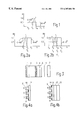
FIG. 1 show graphically the reflecting wavelength range of a cholesteric polarization filter relative to the wavelength range of a luminescent layer;
FIG. 2a shows graphically the reflecting wavelength range of a cholesteric light collection filter relative to the wavelength range of a luminescent layer;
FIG. 2b shows graphically the degree of reflection of a combination of layers having polarinzation and collection properties;
FIG. 3 shows diagrammatically in combination a cathodoluminescent light source, a quarter wave plate and an LCD;
FIG. 4a shows diagrammatically a partial area of a flat colour display screen with integrated cholesteric light collection filters; and
FIG. 4b shows diagrammatically a partial area of a flat colour display screen with integrated cholesteric filter which operate as illustrated in FIG. 2b and in which additional measures for absorption of ambient light have been taken.
FIG. 1 shows the degree ofrefection R of a laevorotatory or dextrorotatofy polarizing cholesteric layer as a function wavelength of λ. In an ideal representation half the quantity of the incident unpolarized light is transmitted in a limited second wavelength range as light circularly polarized in a given direction of rotation, whereas the other half of the quantity of the incident light is reflected as light circularly polarized in the opposite direction. The positon of this wavelength range is dependent on the angle θ between the direction of the incident radiation and the normal on the cholesteric layer. For θ=0 there is a reflecting range between λ1, and λ2, for θ=60° the range is between λ3 and λ4. The characteristic curve L shows the wavelength-dependent relative intensity of the light incident on the cholesteric layer. The radiation of the luminescent layer is in a first wavelength range the wavelength range between λ1 and λ4 so that half the quantity of this radiation directly passes as polarized light through the cholesteric layer in the range of 60 °>θ>0. The reflected radiation is largely depolarized by luminescent layer and reflected back. Consequently, approximately half the quanity of the radiation which is reflected back can additionally pass through the cholesteric layer as circularly polarized light. The process of reflection from the cholesteric layer and the reflection back from the luminescent layer may be repeated several times so that, while allowing for unavoidable absorption losses, up to 80% of the unpolarized exit light passes through the cholesteric layer as circularly polarized light.
The width of the wavelength ranges λ1−λ2 and λ3−λ4 can be chosen in such a way that an at least predominant part of the spectrum of the luminescent layer between θ=0° and an angle θ located close to the radiation angle of the luminescent radiation (θ=60° in the example) is reflected. It is advantageous that the limit wavelength λ1 for θ=0° is close to the smaller limit wavelength of the luminescent light. In accordance with FIG. 1 a light source for circularly polarized light is obtained in which up to 80% of the unpolarized exit light is converted into circularly polarized light instead of up to 50%, as with conventional polarizers.
FIG. 2a shows the degree of reflection of a successive arrangement of two cholesteric layers circularly polarizing in opposite directions for the angles θ=0 and θ=60°, analogous to FIG. 1. In contrast to FIG. 1 the wavelength range of the luminescent radiation L is outside, though close to a third wavelength range the wavelength range between λ1′ and λ2′ in which the two cholesteric layers reflect the complete light occurring at θ=0°. This means that luminescent light occurring at the angle θ=0° completely passes through the cholesteric layers. However, the reflecting range of the cholesteric layer in the case of radiation incident θ=60° is shifted between values of λ3′ and λ4′ so that radiation incident at θ>60° is initially completely reflected towards the luminescent layer. From this layer, it is, however, reflected back at angles of radiation predominantly in the range of 0 <θ>60° and can then pass through the cholesteric layers, while the process of reflection and back-reflection can be repeated several times. In the final result the part of the luminescent radiation radiated at too large angles θ is converted into radiation having a considerably smaller angle θ with a high efficiency. For a satisfactory efficiency it is advantageous that the limit wavelengths λ3′ and λ4′ are possibly close to the limit wavelengths of the spectrum of luminescent radiation. As a consequence of the combination with a luminescent layer, the two cholesteric layers circularly polarizing in opposite directions act as a light collection filter having a high degree of transmissivity.
In a layer arrangement according to FIG. 2b in connection with a luminescent layer, an optical filter is obtained which with a high efficiency simultaneously polarizes circularly and concentrates the exit light to a narrow radiation angular range in the forward direction. In FIG. 2b the degree of reflection in the case of perpendicularly incident light is shown in solid lines, whereas the degree of reflection at 60° is shown in broken lines. The characteristic curves shown are obtained when two cholesteric layers polarizingin opposite directions are superimposed. One of these layers is formed in accordance with FIG. 1 and the other is formed analogously to one of the layers in accordance with FIG. 2 The same designations are used for the limit values of the wavelengths.
FIGS. 3, 4 a and 4 b show examples of particularly advantageous uses of cholesteric filters according to the invention.
In accordance with FIG. 3, a cathodoluminescent light source (cf. DE-OS 38 36 955) comprises a cathode 1, a grid 2, a luminescent layer 3, a transparent substrate 4 and a three-layer cholesteric filter 5 in accordance with FIG. 2b. The cholesteric filter passes circularly polarzed light in a concentrated radiation beam via a λ/4 element 6 to an LCD device 7 with LCD cells which and are arranged in the form of a matrix and can be driven. The circularly polarized light by the λ4 element 6 is converted into linearly polarized light substantially without any loss, which linearly polarized light is required for driving the LCD cells of the LCD 7.
In the arrangement shown in FIG. 3 approximately 70% of the exit light of the luminescent layer is guided towards the LCD tube 7 instead of less than 50%, as in the known case. In the known case a required polarizer would in fact obstruct more than 50% and an interference filter would obstruct an additional part of the exit light.
FIG. 4a shows a partial area of a flat colour display screen. Such a display screen comprises interleaved grating-shaped patterns of red (R), green (G), and blue (B) luminescing pixels 8 which are selectively irradiated with electrons by means of cathode arrangements (for example, of the field emitter type) not shown (cf. PCT/US 87/01747).
The cholesteric filter elements have two layers in accordance with FIG. 2 and, similarly as an interference filter, enable a greater luminescence in the forward direction. However, in contrast to an interference filter, a cholesteric filter operating in a similar way can be manufactured much more easily. More specifically, the filter effect is substantially independent of variations of the layer thickness. It should of course be taken in account that temperatures of more than 200° C. should be avoided when manufacturing an arrangement comprising cholesteric layers, because the organic cholesteric layers would be destroyed at such high temperatures.
In a modification shown in FIG. 4b, the cholesteric filter elements 10 shown in FIG. 4a are replaced by cholesteric filter elements 14 in accordance with FIG. 2b. A λ/4 element 12 and a polarizer 13 are additionally provided. The λ4 element 12 converts the incident circularly polarized light into linearly polarized light. The polarizer 13 is arranged in such a way that this linearly polarized light is completely passed. On the other hand at most half the quantity of the exterior ambient light incident on the polarizer 13 can be reflected, while the rest is absorbed. Thus, a structure in which the effect of the “black matrix” is augmented is realized in a simple manner.
Claims (6)
1. A light source having a luminescent layer, means for stimulating light emission from the layer in a first wavelength range, and a cholesteric filter comprising at least one cholesteric crystal layer for filtering the emitted light, characterized in that the cholesteric filter is a light collection filter comprising first and second successively arranged cholesteric crystal layers, the first of which polarizes light in a dextrorotatory sense and the second of which polarizes light in a laevorotatory sense, in the same wavelength range, the light collection filter completely reflecting perpendicularly incident light over a second wavelength range which is slightly above the first wavelength range of the luminescent light.
2. A light source as claimed in claim 1, characterized in that the luminescent elements of different colors, each of a pattern of luminescent elements of different colors, each of said luminescent elements emitting light in first wavelength ranges and each of the luminescent elements being provided with one of said cholesteric filters.
3. A light source as claimed in claim 1, in combination with a substrate (9) arranged in front of the light source, a λ/4 element (12) arranged in front of the substrate (9), and an absorbing polarizer (13) arranged in front of the λ/4 element characterized in that the luminescent layer defines a flat color display screen having a pattern of luminescent elements of different colors, each of said luminescent elements emitting light in said first wavelength range and each of the luminescent elements being provides with one of said cholesteric filters.
4. A light source as claimed in claim 1, characterized in that the luminescent layer defines a flat color display screen having a pattern of luminescent elements of different colors, each of said luminescent elements emitting light in first wavelength ranges and each of the luminescent elements being provided with one of said cholesteric filters.
5. A light source as claimed in claim 1, in combination with a an LCD matrix device for projection television, and a λ/4 element arranged between the light source and the LCD device.
6. A light source having a luminescent layer, means for stimulating light emission from the layer, a cholesteric filter comprising at, least one cholesteric crystal layer for filtering the emitted light, characterized in that the cholesteric filter comprises a first cholesteric crystal layer and a second cholesteric crystal layer having a sense of polarization rotation opposite to that of the first cholesteric layer, the first cholesteric crystal layer polarizing light in a first wavelength range and the second cholesteric crystal layer polarizing light in a second wavelength range, both ranges having approximately the same lower limits, the lower limit of the first wavelength range being approximately the same of the wavelength range of the luminescent light and the upper limit of the second wavelength range being slightly above that of the wavelength range of the luminescent light.
Priority Applications (1)
| Application Number | Priority Date | Filing Date | Title |
|---|---|---|---|
| US08/382,937 US6307604B1 (en) | 1992-07-04 | 1995-02-02 | Light source having a luminescent layer |
Applications Claiming Priority (4)
| Application Number | Priority Date | Filing Date | Title |
|---|---|---|---|
| DE4222028 | 1992-07-04 | ||
| DE4222028A DE4222028A1 (en) | 1992-07-04 | 1992-07-04 | Light source with a luminescent layer |
| US8681293A | 1993-07-02 | 1993-07-02 | |
| US08/382,937 US6307604B1 (en) | 1992-07-04 | 1995-02-02 | Light source having a luminescent layer |
Related Parent Applications (1)
| Application Number | Title | Priority Date | Filing Date |
|---|---|---|---|
| US8681293A Continuation | 1992-07-04 | 1993-07-02 |
Publications (1)
| Publication Number | Publication Date |
|---|---|
| US6307604B1 true US6307604B1 (en) | 2001-10-23 |
Family
ID=6462506
Family Applications (1)
| Application Number | Title | Priority Date | Filing Date |
|---|---|---|---|
| US08/382,937 Expired - Lifetime US6307604B1 (en) | 1992-07-04 | 1995-02-02 | Light source having a luminescent layer |
Country Status (4)
| Country | Link |
|---|---|
| US (1) | US6307604B1 (en) |
| EP (1) | EP0578302B1 (en) |
| JP (2) | JP3810808B2 (en) |
| DE (2) | DE4222028A1 (en) |
Cited By (20)
| Publication number | Priority date | Publication date | Assignee | Title |
|---|---|---|---|---|
| US20010055208A1 (en) * | 2000-06-15 | 2001-12-27 | Koichi Kimura | Optical element, optical light source unit and optical display device equipped with the optical light source unit |
| WO2003077018A1 (en) * | 2002-03-14 | 2003-09-18 | Nitto Denko Corporation | Back light and liquid crystal display unit using this |
| WO2003077017A1 (en) * | 2002-03-14 | 2003-09-18 | Nitto Denko Corporation | Liquid crystal display unit |
| US6667788B1 (en) * | 1999-06-15 | 2003-12-23 | Nec Lcd Technologies, Ltd. | Method for producing image on liquid crystal panel, liquid crystal panel and liquid crystal display equipped with the same |
| US6667794B2 (en) * | 2000-09-25 | 2003-12-23 | Fuji Photo Film Co., Ltd. | Collimator utilizing wavelength selective reflection and backlight system |
| US20050088740A1 (en) * | 2003-10-23 | 2005-04-28 | Nitto Denko Corporation | Rotatory polarization plate, optical element, light condensation backlight system and liquid crystal display |
| US20050151896A1 (en) * | 2002-04-23 | 2005-07-14 | Kazutaka Hara | Polarizer, polarization light source and image displayunit using them |
| US20050180017A1 (en) * | 2002-04-24 | 2005-08-18 | Kazutaka Hara | Light converging system and transmission liquid crystal display |
| US20050200776A1 (en) * | 2002-04-24 | 2005-09-15 | Kazutaka Hara | Viewing angle magnification liquid crystal display unit |
| US20060028146A1 (en) * | 2002-06-21 | 2006-02-09 | Hitachi, Ltd. | Display device |
| US20060036365A1 (en) * | 2002-08-15 | 2006-02-16 | Chiayee Steve C | Interface for a gps system |
| US20060285037A1 (en) * | 2005-06-21 | 2006-12-21 | Chi Lin Technology Co., Ltd. | Apparatus for mixing light beams and backlight module having the same |
| US20070014127A1 (en) * | 2003-09-02 | 2007-01-18 | Nitto Denko Corporation | Light source device and crystal display device |
| US20070097291A1 (en) * | 2005-10-31 | 2007-05-03 | Hewlett-Packard Development Company, Lp | Polymer dispersed liquid crystal |
| US20070097478A1 (en) * | 2005-10-31 | 2007-05-03 | Hewlett-Packard Development Company, L.C. | Charge responsive optical material |
| US20070132914A1 (en) * | 2003-10-23 | 2007-06-14 | Nitto Denko Corporation | Optical element, light condensation backlight system, and liquid crystal display |
| WO2008007782A1 (en) | 2006-07-13 | 2008-01-17 | Zeon Corporation | Method for producing circularly polarized light isolation sheet, and apparatus for coating film formation |
| US7612859B2 (en) | 2005-10-31 | 2009-11-03 | Hewlett-Packard Development Company, L.P. | Ultra-violet radiation absorbing grid |
| US7852560B2 (en) | 1993-12-21 | 2010-12-14 | 3M Innovative Properties Company | Display incorporating reflective polarizer |
| US20120120354A1 (en) * | 2009-12-18 | 2012-05-17 | Stephen Kitson | Cholesteric reflector |
Families Citing this family (41)
| Publication number | Priority date | Publication date | Assignee | Title |
|---|---|---|---|---|
| GB2296807A (en) * | 1994-12-29 | 1996-07-10 | Sharp Kk | Illumination system |
| US5691790A (en) * | 1995-08-04 | 1997-11-25 | Raychem Corporation | Colored liquid crystal display having a reflector which reflects different wavelengths of light for different incident angles |
| GB9607994D0 (en) * | 1996-04-18 | 1996-06-19 | Screen Tech Ltd | Liquid crystal display element |
| US7049761B2 (en) | 2000-02-11 | 2006-05-23 | Altair Engineering, Inc. | Light tube and power supply circuit |
| JP2004004149A (en) * | 2002-04-23 | 2004-01-08 | Nitto Denko Corp | Neutral polarization plate and image display device |
| JP4233431B2 (en) | 2003-04-01 | 2009-03-04 | 日東電工株式会社 | Optical element, polarizing element, illumination device, and liquid crystal display device |
| US8118447B2 (en) | 2007-12-20 | 2012-02-21 | Altair Engineering, Inc. | LED lighting apparatus with swivel connection |
| US7712918B2 (en) | 2007-12-21 | 2010-05-11 | Altair Engineering , Inc. | Light distribution using a light emitting diode assembly |
| US8360599B2 (en) | 2008-05-23 | 2013-01-29 | Ilumisys, Inc. | Electric shock resistant L.E.D. based light |
| US7976196B2 (en) | 2008-07-09 | 2011-07-12 | Altair Engineering, Inc. | Method of forming LED-based light and resulting LED-based light |
| US7946729B2 (en) | 2008-07-31 | 2011-05-24 | Altair Engineering, Inc. | Fluorescent tube replacement having longitudinally oriented LEDs |
| US8674626B2 (en) | 2008-09-02 | 2014-03-18 | Ilumisys, Inc. | LED lamp failure alerting system |
| US8256924B2 (en) | 2008-09-15 | 2012-09-04 | Ilumisys, Inc. | LED-based light having rapidly oscillating LEDs |
| US8444292B2 (en) | 2008-10-24 | 2013-05-21 | Ilumisys, Inc. | End cap substitute for LED-based tube replacement light |
| US8214084B2 (en) | 2008-10-24 | 2012-07-03 | Ilumisys, Inc. | Integration of LED lighting with building controls |
| US8653984B2 (en) | 2008-10-24 | 2014-02-18 | Ilumisys, Inc. | Integration of LED lighting control with emergency notification systems |
| US8901823B2 (en) | 2008-10-24 | 2014-12-02 | Ilumisys, Inc. | Light and light sensor |
| US8324817B2 (en) | 2008-10-24 | 2012-12-04 | Ilumisys, Inc. | Light and light sensor |
| US7938562B2 (en) | 2008-10-24 | 2011-05-10 | Altair Engineering, Inc. | Lighting including integral communication apparatus |
| US8556452B2 (en) | 2009-01-15 | 2013-10-15 | Ilumisys, Inc. | LED lens |
| US8362710B2 (en) | 2009-01-21 | 2013-01-29 | Ilumisys, Inc. | Direct AC-to-DC converter for passive component minimization and universal operation of LED arrays |
| US8664880B2 (en) | 2009-01-21 | 2014-03-04 | Ilumisys, Inc. | Ballast/line detection circuit for fluorescent replacement lamps |
| US8330381B2 (en) | 2009-05-14 | 2012-12-11 | Ilumisys, Inc. | Electronic circuit for DC conversion of fluorescent lighting ballast |
| US8299695B2 (en) | 2009-06-02 | 2012-10-30 | Ilumisys, Inc. | Screw-in LED bulb comprising a base having outwardly projecting nodes |
| EP2446715A4 (en) | 2009-06-23 | 2013-09-11 | Ilumisys Inc | Illumination device including leds and a switching power control system |
| WO2011119958A1 (en) | 2010-03-26 | 2011-09-29 | Altair Engineering, Inc. | Inside-out led bulb |
| US9057493B2 (en) | 2010-03-26 | 2015-06-16 | Ilumisys, Inc. | LED light tube with dual sided light distribution |
| US8541958B2 (en) | 2010-03-26 | 2013-09-24 | Ilumisys, Inc. | LED light with thermoelectric generator |
| US8454193B2 (en) | 2010-07-08 | 2013-06-04 | Ilumisys, Inc. | Independent modules for LED fluorescent light tube replacement |
| EP2593714A2 (en) | 2010-07-12 | 2013-05-22 | iLumisys, Inc. | Circuit board mount for led light tube |
| WO2012058556A2 (en) | 2010-10-29 | 2012-05-03 | Altair Engineering, Inc. | Mechanisms for reducing risk of shock during installation of light tube |
| US8870415B2 (en) | 2010-12-09 | 2014-10-28 | Ilumisys, Inc. | LED fluorescent tube replacement light with reduced shock hazard |
| US9072171B2 (en) | 2011-08-24 | 2015-06-30 | Ilumisys, Inc. | Circuit board mount for LED light |
| WO2013131002A1 (en) | 2012-03-02 | 2013-09-06 | Ilumisys, Inc. | Electrical connector header for an led-based light |
| WO2014008463A1 (en) | 2012-07-06 | 2014-01-09 | Ilumisys, Inc. | Power supply assembly for led-based light tube |
| US9271367B2 (en) | 2012-07-09 | 2016-02-23 | Ilumisys, Inc. | System and method for controlling operation of an LED-based light |
| US9285084B2 (en) | 2013-03-14 | 2016-03-15 | Ilumisys, Inc. | Diffusers for LED-based lights |
| US9267650B2 (en) | 2013-10-09 | 2016-02-23 | Ilumisys, Inc. | Lens for an LED-based light |
| JP2017504166A (en) | 2014-01-22 | 2017-02-02 | イルミシス, インコーポレイテッドiLumisys, Inc. | LED-based lamp with LED addressed |
| US9510400B2 (en) | 2014-05-13 | 2016-11-29 | Ilumisys, Inc. | User input systems for an LED-based light |
| US10161568B2 (en) | 2015-06-01 | 2018-12-25 | Ilumisys, Inc. | LED-based light with canted outer walls |
Citations (11)
| Publication number | Priority date | Publication date | Assignee | Title |
|---|---|---|---|---|
| US3669525A (en) * | 1971-01-06 | 1972-06-13 | Xerox Corp | Liquid crystal color filter |
| US3697152A (en) * | 1971-01-06 | 1972-10-10 | Xerox Corp | Tuning method for plural layer liquid crystal filters |
| US4073571A (en) * | 1976-05-05 | 1978-02-14 | Hughes Aircraft Company | Circularly polarized light source |
| EP0154953A2 (en) | 1984-03-12 | 1985-09-18 | Matsushita Electric Industrial Co., Ltd. | Optical filter and the method of preparing the same |
| EP0302619A2 (en) * | 1987-08-03 | 1989-02-08 | Kaiser Aerospace And Electronics Corporation | Opticle collimating apparatus |
| US4882617A (en) * | 1986-12-24 | 1989-11-21 | U.S. Philips Corporation | Projection device and associated electro-optic monochrome display device with phosphor layer and interference filters |
| US4900133A (en) * | 1988-10-27 | 1990-02-13 | Kaiser Electronics | Heads-up display combiner utilizing a cholesteric liquid crystal element |
| US5016985A (en) * | 1988-06-24 | 1991-05-21 | Kaiser Aerospace & Electronics Corporation | Infrared filter using cholesteric liquids |
| US5089883A (en) | 1988-10-29 | 1992-02-18 | U.S. Philips Corporation | Color television projection device with cathodoluminescent light sources |
| US5193015A (en) * | 1989-10-05 | 1993-03-09 | Thorn Emi Plc | Cholesteric liquid crystal screen which reflects substantially all of the projected light |
| US5235443A (en) | 1989-07-10 | 1993-08-10 | Hoffmann-La Roche Inc. | Polarizer device |
Family Cites Families (2)
| Publication number | Priority date | Publication date | Assignee | Title |
|---|---|---|---|---|
| DE59010516D1 (en) * | 1989-07-10 | 1996-10-31 | Hoffmann La Roche | Polarizer |
| JPH04221990A (en) * | 1990-12-25 | 1992-08-12 | Sony Corp | Image display device |
-
1992
- 1992-07-04 DE DE4222028A patent/DE4222028A1/en not_active Withdrawn
-
1993
- 1993-06-28 DE DE59309755T patent/DE59309755D1/en not_active Expired - Fee Related
- 1993-06-28 EP EP93201875A patent/EP0578302B1/en not_active Expired - Lifetime
- 1993-06-30 JP JP16260193A patent/JP3810808B2/en not_active Expired - Lifetime
-
1995
- 1995-02-02 US US08/382,937 patent/US6307604B1/en not_active Expired - Lifetime
-
2006
- 2006-04-05 JP JP2006103709A patent/JP2006293355A/en active Pending
Patent Citations (11)
| Publication number | Priority date | Publication date | Assignee | Title |
|---|---|---|---|---|
| US3669525A (en) * | 1971-01-06 | 1972-06-13 | Xerox Corp | Liquid crystal color filter |
| US3697152A (en) * | 1971-01-06 | 1972-10-10 | Xerox Corp | Tuning method for plural layer liquid crystal filters |
| US4073571A (en) * | 1976-05-05 | 1978-02-14 | Hughes Aircraft Company | Circularly polarized light source |
| EP0154953A2 (en) | 1984-03-12 | 1985-09-18 | Matsushita Electric Industrial Co., Ltd. | Optical filter and the method of preparing the same |
| US4882617A (en) * | 1986-12-24 | 1989-11-21 | U.S. Philips Corporation | Projection device and associated electro-optic monochrome display device with phosphor layer and interference filters |
| EP0302619A2 (en) * | 1987-08-03 | 1989-02-08 | Kaiser Aerospace And Electronics Corporation | Opticle collimating apparatus |
| US5016985A (en) * | 1988-06-24 | 1991-05-21 | Kaiser Aerospace & Electronics Corporation | Infrared filter using cholesteric liquids |
| US4900133A (en) * | 1988-10-27 | 1990-02-13 | Kaiser Electronics | Heads-up display combiner utilizing a cholesteric liquid crystal element |
| US5089883A (en) | 1988-10-29 | 1992-02-18 | U.S. Philips Corporation | Color television projection device with cathodoluminescent light sources |
| US5235443A (en) | 1989-07-10 | 1993-08-10 | Hoffmann-La Roche Inc. | Polarizer device |
| US5193015A (en) * | 1989-10-05 | 1993-03-09 | Thorn Emi Plc | Cholesteric liquid crystal screen which reflects substantially all of the projected light |
Non-Patent Citations (9)
| Title |
|---|
| Adams et al. "Cholesteric Films as Optical Filters" Journal of Applied Physics-vol. 42-No. 10-Sep. 1971, pp. 4096-4098.* |
| Adams et al. "Cholesteric Films as Optical Filters" Journal of Applied Physics—vol. 42—No. 10—Sep. 1971, pp. 4096-4098.* |
| Adams et al., "Lossless Polarizer" Xerox Disclosure Journal-vol. 1-No. 3-Mar. 1976-pp. 85-86.* |
| Adams et al., "Lossless Polarizer" Xerox Disclosure Journal—vol. 1—No. 3—Mar. 1976—pp. 85-86.* |
| F. J. Kahn "Cholesteric Liquid Crystals For Optical Applications" Applied Physics Letters-vol. 18, No. 6-Mar. 1971-pp. 231-233.* |
| F. J. Kahn "Cholesteric Liquid Crystals For Optical Applications" Applied Physics Letters—vol. 18, No. 6—Mar. 1971—pp. 231-233.* |
| Melamed et al "Selected Optical Properties of Mixtures of Cholesteric Liquid Crystals" Applied Optics-vol. 10, No. 5-May 1971-pp. 1103-1107.* |
| Melamed et al "Selected Optical Properties of Mixtures of Cholesteric Liquid Crystals" Applied Optics-vol. 10, No. 5—May 1971—pp. 1103-1107.* |
| Philips Research Bulletin on Materials 1991, "Scanning tunnelling microscopy" pp. 5-16. No date. |
Cited By (44)
| Publication number | Priority date | Publication date | Assignee | Title |
|---|---|---|---|---|
| US7852560B2 (en) | 1993-12-21 | 2010-12-14 | 3M Innovative Properties Company | Display incorporating reflective polarizer |
| US6667788B1 (en) * | 1999-06-15 | 2003-12-23 | Nec Lcd Technologies, Ltd. | Method for producing image on liquid crystal panel, liquid crystal panel and liquid crystal display equipped with the same |
| US6798469B2 (en) * | 2000-06-15 | 2004-09-28 | Fuji Photo Film Co., Ltd. | Optical element, optical light source unit and optical display device equipped with the optical light source unit |
| US20010055208A1 (en) * | 2000-06-15 | 2001-12-27 | Koichi Kimura | Optical element, optical light source unit and optical display device equipped with the optical light source unit |
| US6667794B2 (en) * | 2000-09-25 | 2003-12-23 | Fuji Photo Film Co., Ltd. | Collimator utilizing wavelength selective reflection and backlight system |
| US20050206804A1 (en) * | 2002-03-14 | 2005-09-22 | Kazutaka Hara | Liquid crystal display unit |
| WO2003077018A1 (en) * | 2002-03-14 | 2003-09-18 | Nitto Denko Corporation | Back light and liquid crystal display unit using this |
| WO2003077017A1 (en) * | 2002-03-14 | 2003-09-18 | Nitto Denko Corporation | Liquid crystal display unit |
| CN100345047C (en) * | 2002-03-14 | 2007-10-24 | 日东电工株式会社 | Back light and liquid crystal display unit using this |
| US20050185112A1 (en) * | 2002-03-14 | 2005-08-25 | Nitto Denko Corporation | Back light and liquid crystal display unit using this |
| US7443585B2 (en) | 2002-04-23 | 2008-10-28 | Nitto Denko Corporation | Polarizer, polarization light source and image display unit using them |
| US7746555B2 (en) | 2002-04-23 | 2010-06-29 | Nitto Denko Corporation | Polarizer, polarization light source and image display unit using them |
| US7982952B2 (en) | 2002-04-23 | 2011-07-19 | Nitto Denko Corporation | Polarization component, polarization light source and image display apparatus using the same |
| US20100226007A1 (en) * | 2002-04-23 | 2010-09-09 | Nitto Denko Corporation | Polarization component, polarization light source and image display apparatus using the same |
| US20050151896A1 (en) * | 2002-04-23 | 2005-07-14 | Kazutaka Hara | Polarizer, polarization light source and image displayunit using them |
| US20090034070A1 (en) * | 2002-04-23 | 2009-02-05 | Nitto Denko Corporation | Polarizer, polarization light source and image display unit using them |
| US20050200776A1 (en) * | 2002-04-24 | 2005-09-15 | Kazutaka Hara | Viewing angle magnification liquid crystal display unit |
| US20050180017A1 (en) * | 2002-04-24 | 2005-08-18 | Kazutaka Hara | Light converging system and transmission liquid crystal display |
| US7317498B2 (en) | 2002-04-24 | 2008-01-08 | Nitto Denko Corporation | Viewing angle magnification liquid crystal display unit |
| US8198804B2 (en) | 2002-06-21 | 2012-06-12 | Hitachi Displays, Ltd. | Display device |
| US7928639B2 (en) | 2002-06-21 | 2011-04-19 | Hitachi Displays, Ltd. | Display device |
| US20110163333A1 (en) * | 2002-06-21 | 2011-07-07 | Masaya Adachi | Display Device |
| US7425794B2 (en) | 2002-06-21 | 2008-09-16 | Hitachi Displays, Ltd. | Display device |
| US20060028146A1 (en) * | 2002-06-21 | 2006-02-09 | Hitachi, Ltd. | Display device |
| US7557494B2 (en) | 2002-06-21 | 2009-07-07 | Hitachi Displays, Ltd. | Display device |
| US20090072731A1 (en) * | 2002-06-21 | 2009-03-19 | Hitachi Displays, Ltd. | Display Device |
| US20060036365A1 (en) * | 2002-08-15 | 2006-02-16 | Chiayee Steve C | Interface for a gps system |
| US7841730B2 (en) | 2003-09-02 | 2010-11-30 | Nitto Denko Corporation | Light source device and crystal display device |
| US8373829B2 (en) | 2003-09-02 | 2013-02-12 | Nitto Denko Corporation | Light source and liquid crystal display |
| US20110037927A1 (en) * | 2003-09-02 | 2011-02-17 | Nitto Denko Corporation | Light source and liquid crystal display |
| US20070014127A1 (en) * | 2003-09-02 | 2007-01-18 | Nitto Denko Corporation | Light source device and crystal display device |
| US20050088740A1 (en) * | 2003-10-23 | 2005-04-28 | Nitto Denko Corporation | Rotatory polarization plate, optical element, light condensation backlight system and liquid crystal display |
| US7326451B2 (en) | 2003-10-23 | 2008-02-05 | Nitto Denko Corporation | Rotatory polarization plate, optical element, light condensation backlight system and liquid crystal display |
| US7746421B2 (en) | 2003-10-23 | 2010-06-29 | Nitto Denko Corporation | Optical element, light condensation backlight system, and liquid crystal display |
| US20070132914A1 (en) * | 2003-10-23 | 2007-06-14 | Nitto Denko Corporation | Optical element, light condensation backlight system, and liquid crystal display |
| US20060285037A1 (en) * | 2005-06-21 | 2006-12-21 | Chi Lin Technology Co., Ltd. | Apparatus for mixing light beams and backlight module having the same |
| US7612859B2 (en) | 2005-10-31 | 2009-11-03 | Hewlett-Packard Development Company, L.P. | Ultra-violet radiation absorbing grid |
| US20070097478A1 (en) * | 2005-10-31 | 2007-05-03 | Hewlett-Packard Development Company, L.C. | Charge responsive optical material |
| US7876400B2 (en) | 2005-10-31 | 2011-01-25 | Hewlett-Packard Development Company, L.P. | Optical modulation system |
| US20070097291A1 (en) * | 2005-10-31 | 2007-05-03 | Hewlett-Packard Development Company, Lp | Polymer dispersed liquid crystal |
| WO2008007782A1 (en) | 2006-07-13 | 2008-01-17 | Zeon Corporation | Method for producing circularly polarized light isolation sheet, and apparatus for coating film formation |
| US20090269502A1 (en) * | 2006-07-13 | 2009-10-29 | Zeon Corporation | Method for producing circular polarization separation sheet, and apparatus for coating layer formation |
| US20120120354A1 (en) * | 2009-12-18 | 2012-05-17 | Stephen Kitson | Cholesteric reflector |
| US8908131B2 (en) * | 2009-12-18 | 2014-12-09 | Hewlett-Packard Development Company, L.P. | Cholesteric reflector |
Also Published As
| Publication number | Publication date |
|---|---|
| EP0578302B1 (en) | 1999-09-01 |
| JP2006293355A (en) | 2006-10-26 |
| DE59309755D1 (en) | 1999-10-07 |
| DE4222028A1 (en) | 1994-01-05 |
| JPH06235900A (en) | 1994-08-23 |
| EP0578302A1 (en) | 1994-01-12 |
| JP3810808B2 (en) | 2006-08-16 |
Similar Documents
| Publication | Publication Date | Title |
|---|---|---|
| US6307604B1 (en) | Light source having a luminescent layer | |
| US6671014B2 (en) | Liquid projection device having a liquid crystal display element that includes an electroluminescent element | |
| KR100257969B1 (en) | Daylight readable liquid crystal display | |
| US5841494A (en) | Transflective LCD utilizing chiral liquid crystal filter/mirrors | |
| JP2708763B2 (en) | Projection device and related display device | |
| US5751385A (en) | Subtractive color LCD utilizing circular notch polarizers and including a triband or broadband filter tuned light source or dichroic sheet color polarizers | |
| US5813752A (en) | UV/blue LED-phosphor device with short wave pass, long wave pass band pass and peroit filters | |
| US4142781A (en) | Electro-optical display device with electro-optical light valves | |
| US5650865A (en) | Holographic backlight for flat panel displays | |
| JP3300642B2 (en) | Image display device | |
| US7306338B2 (en) | Image projection system with a polarizing beam splitter | |
| US8040043B2 (en) | Display device and luminous panel | |
| MXPA04005915A (en) | Color pre-filter for single-panel projection display system. | |
| JP2001264759A (en) | Liquid crystal display screen | |
| KR19990082028A (en) | Reflective Flat Panel Display | |
| RU2001125727A (en) | Liquid crystal display with reflective polarizer | |
| US6256120B1 (en) | Spatial light modulation device and color display apparatus | |
| JPH09189910A (en) | Color display device | |
| JPH0777691A (en) | Polarization light source body | |
| KR19990075731A (en) | Active light emitting liquid crystal display device | |
| JPS61256376A (en) | Color liquid crystal display unit | |
| Hsiang et al. | 62‐4: Distinguished Student Paper: Doubling the Optical Efficiency of Color‐Converted MicroLED Displays with a Patterned Cholesteric Liquid‐Crystal Polymer Film | |
| JPH07253577A (en) | Color display device | |
| JPH09311641A (en) | Color display device | |
| CN110794615A (en) | Backlight module and display device |
Legal Events
| Date | Code | Title | Description |
|---|---|---|---|
| STCF | Information on status: patent grant |
Free format text: PATENTED CASE |
|
| FPAY | Fee payment |
Year of fee payment: 4 |
|
| FPAY | Fee payment |
Year of fee payment: 8 |
|
| REMI | Maintenance fee reminder mailed | ||
| FPAY | Fee payment |
Year of fee payment: 12 |
|
| SULP | Surcharge for late payment |
Year of fee payment: 11 |