US6307554B1 - Apparatus and method for generating progressive polygon data, and apparatus and method for generating three-dimensional real-time graphics using the same - Google Patents
Apparatus and method for generating progressive polygon data, and apparatus and method for generating three-dimensional real-time graphics using the same Download PDFInfo
- Publication number
- US6307554B1 US6307554B1 US09/071,830 US7183098A US6307554B1 US 6307554 B1 US6307554 B1 US 6307554B1 US 7183098 A US7183098 A US 7183098A US 6307554 B1 US6307554 B1 US 6307554B1
- Authority
- US
- United States
- Prior art keywords
- polygon data
- vertex
- detailed
- polygon
- polyhedron
- Prior art date
- Legal status (The legal status is an assumption and is not a legal conclusion. Google has not performed a legal analysis and makes no representation as to the accuracy of the status listed.)
- Expired - Lifetime
Links
Images


Classifications
-
- G—PHYSICS
- G06—COMPUTING; CALCULATING OR COUNTING
- G06T—IMAGE DATA PROCESSING OR GENERATION, IN GENERAL
- G06T17/00—Three dimensional [3D] modelling, e.g. data description of 3D objects
- G06T17/20—Finite element generation, e.g. wire-frame surface description, tesselation
Definitions
- the present invention relates to an apparatus and a method for generating progressive polygon data, and an apparatus and a method for generating three-dimensional real-time graphics using the progressive polygon data.
- Japanese Laid-Open Patent Publication (Tokkai-Hei) No.7-85307 discloses a technique for the reduction of the polygon data used for rendering an individual object, when a plurality of objects are rendered.
- this technique a plurality of sets of polygon data that have different resolutions are prepared previously, and the resolutions are changed depending on what is rendered, e.g., what kind of behavior is rendered or the like.
- This method makes it possible to reduce the number of polygons according to the behavior of an object or the like when rendering the object, so that this method is effective to display a plurality of objects on the screen.
- a progressive polygon data generator includes a basic vertex determinator for determining vertices of a basic polyhedron approximate to a shape of a 3D object, a detailed vertex determinator for determining vertices of a polyhedron in a level of approximation to the object that is higher than the basic polyhedron progressively, based on the level of approximation, and a detailed vertex coordinate calculator for progressively calculating coordinates of vertices of a polyhedron determined by the detailed vertex determinator in a coordinate system determined based on a plurality of predetermined vertices of a polyhedron in a level of approximation that is lower than the polyhedron.
- the basic vertex determinator determines vertices of the basic polyhedron by selection of an operator.
- a progressive polygon data generator includes a basic vertex determinator for determining vertices of polygons approximate to cross-sections virtually segmenting a 3D object as vertices of a basic polyhedron approximate to a shape of the 3D object, a detailed vertex determinator for determining vertices of a polyhedron in a level of approximation to the object that is higher than the basic polyhedron progressively based on the level of approximation, and a detailed vertex coordinate calculator for calculating coordinates of vertices of a polyhedron progressively determined by the detailed vertex determinator in a coordinate system determined based on a plurality of predetermined vertices of a polyhedron in a level of approximation that is lower than the polyhedron.
- the polygon approximate to each cross-section is a quadrilateral defined by four vertices that divide a total length of sides of the second polygonal shape into four equal lengths.
- the detailed vertex determinator progressively determines vertices of a polygon the number of which is increased so that the level of approximation to the cross-section is higher than the polygon approximate to the cross-section as detailed vertices, based on the increased number of vertices. This is because information about the position of the detailed vertex can be stored in a simplified form.
- the detailed vertex determinator includes an approximation level calculator for calculating a difference between a length of each side of the quadrilateral and a total length of sides of the second polygonal shape between both ends of each side of the quadrilateral, a comparator for comparing the difference calculated by the approximation level calculator with a predetermined value, and a progressive vertex determinator for determining a point that divides into two equal lengths the total length of the sides of the second polygonal shape between both ends of the side of the quadrilateral as a vertex of a polygon in a higher level of approximation when the comparator determines that the difference is the predetermined value or more, and not determining a vertex of a polygon in a higher level of approximation when the difference is determined to be smaller than the predetermined value.
- the approximation level calculator calculates the difference with respect to a newly produced side of the polygon whose vertex is determined, and the progressive vertex determinator determines a vertex of a polygon in a higher level of approximation recursively, until the progressive vertex determinator no longer determines a vertex of a polygon in a higher level of approximation.
- the detailed vertex is determined by this process, it is possible to produce suitable 3D polygon data in accordance with the number of 3D polygons that are desired to be used for rendering.
- the detailed vertex determinator includes an approximation level calculator for calculating a difference between an area of each face of the basic polyhedron and an area on a surface of the 3D object defined by line segments connecting vertices of each face of the basic polyhedron, a comparator for comparing the difference calculated by the approximation level calculator with a predetermined value, and a progressive vertex determinator for determining a new vertex closer to the surface of the 3D object than the face when the comparator determines that the difference is the predetermined value or more, and not determining a new vertex when the difference is determined to be smaller than the predetermined value.
- an approximation level calculator for calculating a difference between an area of each face of the basic polyhedron and an area on a surface of the 3D object defined by line segments connecting vertices of each face of the basic polyhedron
- a comparator for comparing the difference calculated by the approximation level calculator with a predetermined value
- a progressive vertex determinator for determining
- the approximation level calculator calculates a difference in the area with respect to a polyhedron defined by the face and the new vertex, and the progressive vertex determinator determines a vertex of a polygon in a higher level of approximation recursively, until the progressive vertex determinator no longer determines a new vertex.
- the detailed vertex is determined by this process as well, it is possible to produce suitable 3D polygon data in accordance with the number of 3D polygons that are desired to be used for rendering.
- the progressive vertex determinator determines as the new vertex a point at which a normal line from a centroid of a corresponding face of a polyhedron intersects a face represented by original polygon data obtained by geometric modeling of the 3D object. This makes it possible to obtain suitable vertices for producing 3D polygon data.
- a method for generating progressive polygon data includes a basic vertex determining step of determining vertices of a basic polyhedron approximate to a shape of a 3D object, a detailed vertex determining step of determining vertices of a polyhedron in a level of approximation to the object that is higher than the basic polyhedron progressively based on the level of approximation, and a detailed vertex coordinate calculating step of calculating coordinates of vertices of a progressively determined polyhedron in a coordinate system determined based on a plurality of predetermined vertices of a polyhedron in a level of approximation that is lower than the polyhedron.
- the detailed vertex determining step and the detailed vertex coordinate calculating step are performed until the level of approximation reaches a predetermined level of approximation.
- the level of approximation is determined by comparing a difference between an area of a face of a polyhedron defined by a vertex determined by the detailed vertex determining step and a plurality of predetermined vertices used for determining a coordinate system in the detailed vertex calculating step and an area of a potion corresponding to the face of the polyhedron represented by original polygon data obtained by geometric modeling of the object with a predetermined value.
- the detailed vertex is determined by this process, it is possible to produce suitable 3D polygon data in accordance with the number of 3D polygons that can be used for rendering.
- a computer-readable recording medium storing a program.
- the program includes a basic vertex determining step of determining vertices of a basic polyhedron approximate to a shape of a 3D object, a detailed vertex determining step of determining vertices of a polyhedron in a level of approximation to the object that is higher than the basic polyhedron progressively based on the level of approximation, and a detailed vertex coordinate calculating step of calculating coordinates of vertices of a progressively determined polyhedron in a coordinate system based on a plurality of predetermined vertices of a polyhedron in a level of approximation that is lower than the polyhedron.
- the detailed vertex determining step and the detailed vertex coordinate calculating step are performed until the level of approximation reaches a predetermined level of approximation.
- a 3D real-time graphics generator includes a rendering polygon number determinator for determining the number of polygons for rendering 3D polygon data, and a 3D polygon data producer for producing 3D polygon data based on progressive polygon data generated by the progressive polygon data generator of the present invention in accordance with the number of polygons determined by the rendering polygon number determinator.
- the 3D polygon data producer produces 3D polygon data by determining vertices constituting 3D polygon data for rendering an object in accordance with the number of polygons determined by the rendering polygon number determinator.
- the utilization of the progressive polygon data of the present invention makes it possible to produce 3D polygon data easily.
- the 3D real-time graphics generator of the present invention further includes a basic vertex changer for changing positions of vertices of the basic polyhedron.
- the 3D polygon data producer calculates absolute coordinates of detailed vertices whose positions are represented by coordinates in a coordinate system determined based on the vertices, based on changed positions of the vertices.
- the sequential computation for detailed vertices after the change of the position of the vertices of the basic polyhedron makes it possible to move the object or change the shape of the object easily.
- the 3D real-time graphics generator further includes an animation data storage for storing a plurality of progressive polygon data added with information about rendering timing, and an animation rendering controller for rendering 3D polygon data produced by the 3D polygon data producer from the progressive polygon data stored in the animation data storage in accordance with the information about rendering timing.
- an animation rendering controller for rendering 3D polygon data produced by the 3D polygon data producer from the progressive polygon data stored in the animation data storage in accordance with the information about rendering timing.
- a plurality of polygon data representing movement of the object or change in the shape are sequentially rendered at a predetermined timing so as to produce animation.
- the use of the present invention facilitates movement of the object and change in the shape or the like, so that the amount of work of the animator can be reduced.
- the rendering polygon number determinator includes a moving speed calculator for calculating a moving speed of an object when 3D polygon data is rendered sequentially, based on the plurality of progressive polygon data and the information about rendering timing stored in the animation data storage.
- the rendering polygon number determinator determines the number of polygons based on the moving speed calculated by the moving speed calculator.
- the moving speed is high, animation is naturally rendered even with a reduced number of polygons. Therefore, the reduction in the number of polygons for rendering an object makes it possible to render more objects.
- the rendering polygon number determinator comprises a Z value obtainer for obtaining a Z value representing a distance from a viewpoint to a position of a rendered object from the progressive polygon data.
- the rendering polygon number determinator determines the number of polygons based on the distance obtained by the Z value obtainer.
- the distance between the viewpoint and the position of the object is long, the object can be rendered smoothly even with a reduced number of polygons. Therefore, the reduction in the number of polygons for rendering an object makes it possible to render more objects.
- the rendering polygon number determinator determines the number of polygons based on information about system resources on which the object is rendered. For example, a suitable number of polygons depends on system resources such as processing performance of CPU, a capacity of a memory or the like.
- a method for generating 3D real-time graphics includes a rendering polygon number determining step of determining the number of polygons for rendering 3D polygon data, and a 3D polygon data producing step of producing 3D polygon data based on progressive polygon data generated by the progressive polygon data generator of the present invention, based on the number of polygons determined by the rendering polygon number determining step.
- a computer-readable recording medium storing a program.
- the program executing a process includes a rendering polygon number determining step of determining the number of polygons for rendering 3D polygon data, and a 3D polygon data producing step of producing 3D polygon data based on progressive polygon data generated by the progressive polygon data generator of the present invention, based on the number of polygons determined in the rendering polygon number determining step.
- the 3D polygon data producing step the 3D polygon data is produced by determining vertices constituting the 3D polygon data for rendering an object, based on the number of polygons determined in the rendering polygon number determining step.
- a computer-readable recording medium storing progressive polygon data.
- 3D polygon data representing an 3D object is produced based on the progressive polygon in accordance with a determined number of polygons.
- the progressive polygon data includes information about vertices of a basic polyhedron approximate to a shape of the 3D object and information about a plurality of detailed vertices obtained by sequentially computing vertices from the vertices of the basic polyhedron in accordance with the determined number of polygons so that a polyhedron in a higher level of approximation to the 3D object is generated.
- the information of the detailed vertices is represented in the form of coordinates in a coordinate system determined based on a plurality of predetermined vertices of a polyhedron not including the detailed vertices.
- FIG. 1 is a block diagram showing the structure of a 3D real-time graphics generator according to one embodiment of the present invention.
- FIG. 2 is a diagram showing an example of a data structure of original polygon data.
- FIG. 3 is a view showing an example of a object for illustrating a method for generating progressive data for an object of a first embodiment.
- FIG. 4 is a view for illustrating a process when converting original polygon data present in the vicinity of a cross-section 403 to control point data.
- FIG. 5 is an enlarged view of a region 404 .
- FIG. 6 is a diagram showing example of results of calculating all control points on the cross-section 403 .
- FIG. 7 is a diagram illustrating a boundary and a starting point.
- FIG. 8 is a diagram illustrating a median point.
- FIG. 9 is a diagram illustrating a median point M 2 between a starting point S and a median point M 1 .
- FIG. 10 is a diagram illustrating the case where another median point M 3 between the median point M 1 and the median point M 2 is obtained.
- FIG. 11 is a diagram illustrating the relative coordinates of the median point M 3 .
- FIG. 12 is a diagram showing an example of a data structure of progressive polygon data in the first embodiment.
- FIG. 13 is a flow chart showing the process procedure of a controller when generating progressive polygon data in the first embodiment.
- FIG. 14 is a view showing an example of a tetrahedron inscribed inside an object.
- FIG. 15 is a view illustrating the process when forming a tetrahedron one face of which is inscribed inside the object.
- FIG. 16 is a view showing how another tetrahedron is produced.
- FIG. 17 is a diagram illustrating relative coordinates of new points.
- FIG. 18 is a diagram showing an example of a data structure of progressive polygon data in a second embodiment.
- FIG. 19 is a flow chart showing the process procedure of a controller when generating progressive polygon data in the second embodiment.
- FIG. 20 is a flow chart showing the process procedure of a controller when controlling the number of polygon data for rendering.
- FIG. 21 is a view when an example of a object is rendered with 10,000 polygons.
- FIG. 22 is a view when the object in FIG. 21 is rendered with 2,000 polygons.
- FIG. 23 is a view when the object in FIG. 21 is rendered with 400 polygons.
- FIG. 24 is a view when the object in FIG. 21 is rendered with 220 polygons.
- FIG. 25 is a view when the object in FIG. 21 is rendered with 200 polygons.
- FIG. 26 is a view when the object in FIG. 21 is viewed from above.
- FIG. 27 is a view when the object in FIG. 22 is viewed from above.
- FIG. 28 is a view when the object in FIG. 23 is viewed from above.
- FIG. 29 is a view when the object in FIG. 24 is viewed from above.
- FIG. 30 is a view when the object in FIG. 25 is viewed from above.
- FIGS. 31A to 30 E are views showing contracted objects.
- FIG. 32 is a view illustrating the management of the number of polygons for rendering, depending on the rendering speed.
- FIG. 33 is a view illustrating translation (parallel movement) of an object.
- FIG. 34 is a view illustrating translation of the object.
- FIG. 35 is a view illustrating translation of the object.
- FIG. 36 is a view illustrating translation of the object.
- FIG. 37 is a view illustrating translation of the object.
- FIG. 38 is a view illustrating translation of the object.
- FIG. 39 is a view illustrating translation of the object.
- FIG. 40 is a view illustrating translation of the object.
- FIG. 41 is a view illustrating partial transformation of the object.
- FIG. 42 is a view illustrating partial transformation of the object.
- FIG. 43 is a view illustrating partial transformation of the object.
- FIG. 44 is a view illustrating partial transformation of the object.
- FIG. 45 is a view illustrating partial transformation of the object.
- FIG. 46 is a view illustrating partial transformation of the object.
- FIG. 47 is a view illustrating partial transformation of the object.
- FIG. 48 is a view illustrating partial transformation of the object.
- FIG. 49 is a view illustrating entire transformation of the object.
- FIG. 50 is a view illustrating entire transformation of the object.
- FIG. 51 is a view illustrating entire transformation of the object.
- FIG. 52 is a view illustrating entire transformation of the object.
- FIG. 53 is a view illustrating entire transformation of the object.
- FIG. 54 is a view illustrating entire transformation of the object.
- FIG. 55 is a view illustrating entire transformation of the object.
- FIG. 56 is a view illustrating entire transformation of the object.
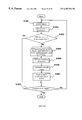
- FIG. 1 is a functional block diagram showing a structural example of a progressive polygon data generator and a 3D real-time graphics generator of the present invention.
- one apparatus can realize both the process for generating progressive polygon data and the process for generating 3D real-time graphics (hereinafter, the apparatus in this embodiment is simply referred to as “3D real-time graphics generator”).
- the process for generating progressive polygon data and the process for generating 3D real-time graphics can be performed in separate apparatuses.
- the 3D real-time graphics generator includes an input part 101 , a controller 102 , an output part 103 , an original polygon data storage 104 , a control point data storage 105 , and a progressive polygon data storage 106 .
- the user inputs and edits the polygon data with the input part 101 .
- Specific examples of the input part 101 are a keyboard or a mouse.
- the controller 102 controls the entire 3D real-time graphics generator of this embodiment. From the aspect of hardware, the controller 102 corresponds to a CPU and I/O interfaces between the CPU and the input/output devices. The controller 102 realizes the process for generating progressive polygon data and the process for generating 3D real-time graphics according to the present invention with a program.
- the controller 102 includes a control point converting part 1021 , a polygon progressing part 1022 , an input receiving part 1023 , a basic polygon data editing part 1024 , a rendering polygon number calculating part 1025 , a merging part 1026 , and a 3D information rendering part 1027 as functional parts.
- the original polygon data storage 104 stores polygon data generated by 3D geometric modeling.
- the 3D polygon data generating process is mainly performed by the control point converting part 1021 and the polygon progressing part 1022 , and the 3D real-time graphics generating process is performed by the other parts. Therefore, the part for generating the progressive polygon data to be stored in the progressive polygon data storage 106 from the original polygon data stored in the original polygon storage 104 can be separated from the other parts and performed in another apparatus. Thus, the progressive polygon data generating process and the 3D real-time graphics generating process can be performed in separate apparatuses. The process procedure of each part of the controller 102 will be detailed later.
- 3D real-time graphics like are displayed on output part 103 , which can be for example an output device of a display apparatus.
- the original polygon data storage 104 stores original polygon data.
- original polygon data Hereinafter, the data structure of the original polygon data will be described.
- FIG. 2 is a diagram showing an example of a data structure of the original polygon data of this embodiment.
- original polygon data 20 include vertex data 201 and triangle polygon data 202 .
- the vertex data 201 includes coordinates (X v , Y v , Z v ) of the vertex of a triangle modeled from a real object together with the identifier ID v of the vertex.
- the triangle polygon data 202 includes a set of identifiers ID v of three vertices forming a triangle face together with the identifier ID F of the triangle face.
- An identifier ID o 203 is assigned to each object and stored. In this embodiment, a triangle is used as the polygon, but a rectangle or other polygonal shapes can be used as well.
- the control point data storage 105 stores control point data converted from the original polygon data 20 .
- the data structure of the control point data will be detailed later.
- the progressive polygon data storage 106 stores progressive polygon data generated by the polygon progressing part 1022 based on the control points.
- the progressive polygon data includes the most coarse polygon data in the uppermost level (hereinafter, referred to as “basic polygon data”) 1061 and polygon data in lower levels than the basic polygon data (hereinafter, referred to as “detailed polygon data”) 1062 .
- the detailed polygon data 1062 represents detailed vertices obtained on the basis of the basic polygon data. Based on the detailed polygon data 1062 , more data for polygons having smaller faces is generated.
- the polygon progressing process and the data structure of the progressive polygon data including the basic polygon data 1061 and the detailed polygon data 1062 generated by the polygon progressing process will be detailed later.
- the control point converting part 1021 converts the original polygon data 20 into control point data.
- the control point converting process will be detailed later.
- the polygon progressing part 1022 generates progressive polygon data from the control point data.
- the input receiving part 1023 receives input instructions for editing the basic polygon data 1061 from the input part 101 .
- the editing process for the basic polygon data 1061 will be detailed in the following.
- the basic polygon data editing part 1024 edits the basic polygon data 1061 in response to the input received by the input receiving part 1023 .
- currently available polygon editing software or the like can be used as the basic polygon data editing part 1024 .
- Edited basic polygon data can be stored separately from the basic polygon data that are not edited.
- the rendering polygon number calculating part 1025 calculates the number of polygons for use in rendering an object on the output part 103 .
- the number of polygons for rendering corresponds to the number of levels of the detailed polygon data 1062 from the basic polygon data 1061 in the progressive polygon data. The method for calculating the rendering polygon number will be detailed later.
- the merging part 1026 performs a process of computing the detailed polygon data 1062 from the basic polygon data 1061 , based on the rendering polygon number obtained by the rendering polygon number calculating part 1025 (hereinafter, referred to as “merging”) and produces 3D polygon data for the object to be rendered on the output part 103 .
- the 3D information rendering part 1027 receives the 3D polygon data processed by the merging part 1026 and renders the object on the output part 103 .
- the 3D information rendering part 1027 stores a tool (not shown) for rendering the object on the output part 103 with the 3D polygon data generated in the 3D real-time graphics generating process in this embodiment.
- Currently available software can be used for this tool.
- SoftImage® by Microsoft Co. was used.
- other software can be used, as long as it can render a 3D object by obtaining data of vertices of polygons and data of surfaces formed by a plurality of vertices representing the 3D polygon data.
- Embodiment 1 of the present invention will be described with reference to the accompanying drawings.
- a first method for generating progressive polygon data from the original polygon data 20 will be described in detail.
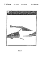
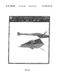
- FIG. 3 is a view showing an example of an object illustrating a method of this embodiment for generating progressive polygon data from the original polygon data 20 .
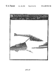
- FIG. 3 shows an object 401 whose original polygon data has been obtained previously by geometric modeling on coordinate axes. In FIG. 3, not all triangles representing the original polygon data are shown.
- first an object 401 is bisected virtually while sequentially changing the z coordinate of a (x, y) plane 402 vertical to the z axis, and the coordinates on the boundary of a cross-section 403 are obtained. In this manner, the original polygon data 20 is converted to control points.
- the object is bisected in the (x, y) plane, but the object also can be bisected in the (y, z) plane or the (z, x) plane.
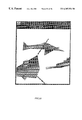
- FIG. 4 is a view for illustrating a process when converting the original polygon data 20 in the vicinity of the cross-section 403 to control point data. As shown in a region 404 of FIG. 4, many faces represented by the original polygon data intersect the cross-section 403 in the vicinity of the cross-section 403 .
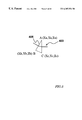
- FIG. 5 shows an enlarged view of the region 404 shown in FIG. 4 .
- the coordinates of the vertices A, B and C of a triangle 405 represented by the original polygon data 20 that intersects the cross-section 403 are (X a , Y a , Z a ), (X b , Y b , Z b ), and (X c , Y c , Z c ), respectively.
- the coordinates of the points on line segments AB and AC with the z coordinate of Z 1 can be obtained.
- the point on the line segment AB with the z coordinate of Z 1 is represented by P, and the point on the line segment AC with the z coordinate of Z 1 is represented by Q.
- the coordinates (X p , Y p , Z p ) of P and the coordinates (X q , Y q , Z q ) of Q can be obtained with the following equations.
- Y p Y a ⁇ ( Z 1 ⁇ Z b )/( Z a ⁇ Z b )
- control points are allotted as “control points”.
- FIG. 6 is a diagram showing an example of results of the calculation for all the control points in the cross-section 403 .
- black squares denote the control points.
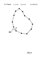
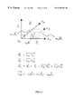
- FIG. 7 is a diagram for illustrating a boundary and a starting point in the polygon progressing process.
- a line segment is formed between each pair of adjacent control points so as to form a boundary 406 , and then a starting point S is selected from the control points on the boundary 406 .
- Any control point among the control points on the boundary 406 can be selected as the starting point S.
- the point closest to the x axis is selected as the starting point S.
- a cross denotes the starting point S.
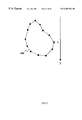
- FIG. 8 is a diagram showing an example of results of the calculation for the median point.
- M 1 denotes the median point.
- L 01 the length from the starting point S to the median point M 1 on the boundary 406 along the upper path in FIG. 8, which is denoted by L 01 , is equal to that along the lower path, which is denoted L′ 01 .
- a length l 01 of a line segment between the starting point S and the median point M 1 is compared with the length L 01 .
- ) of the difference between the lengths l 01 and L 01 is below a predetermined value ⁇ , the polygon progressing process is not performed any more.
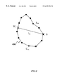
- FIG. 9 is a diagram showing the median point between the starting point S and the median point M 1 .
- M 2 denotes the median point between the starting point S and the median point M 1 .
- the length from the starting point S to the median point M 2 on the boundary 406 which is denoted by L 02 , is equal to the length from the starting point M 1 to the median point M 2 , which is denoted L 12 .
- Another point M′ 2 on the other side can be obtained as the median point between the starting point S and the median point M 1 , but subsequent processes will be described by taking the median point M 2 as an example. The process described below also can be applied to the median point M′ 2 .
- L 02 denotes a length from the starting point S to the median point M 2 on the boundary 406 , as described above, and l 02 denotes a length of a line segment SM 2 .
- L 12 denotes a length from the median points M 1 and M 2 on the boundary 406 , as described above, and l 12 denotes a length of a line segment M 1 M 2 .
- the lengths L 02 and L 12 are equal, but the lengths l 02 and l 12 are different.
- a difference between L 02 and l 02 and a difference between L 12 and l 12 are obtained, and the absolute value (
- ⁇ no further median point is obtained.
- the absolute value of the difference is equal to ⁇ or more, a further median point between the starting point and the median point or between the median points is obtained.
- FIG. 10 is a diagram for illustrating the case where a further median point M 3 is obtained between the median points M 1 and M 2 .
- ) of the difference between L 02 and l 02 is below the predetermined value ⁇ , there is no need to obtain a further median point between the starting point S and the median point M 2 .
- ) of the difference between L 12 and l 12 is equal to the predetermined value ⁇ or more, a further median point M 3 is obtained between the median points M 1 and M 2 .
- the thus obtained starting point S and median points M 1 , M 2 , M 3 , . . . constitute vertex data in the form of progressive polygon data.
- the starting point S and the median points M 1 and M 2 (and M′ 2 ) obtained in the early stage constitute the basic polygon data 1061
- the median point M 3 and other detailed median points following M 3 constitute the detailed polygon data 1062 for a larger number of polygons, which are sequentially computed from the basic polygon data 1061 .
- the basic polygon data 1061 is used when the number of polygons for displaying on the screen is the smallest. Therefore, the basic polygon data 1061 can be stored in the form of absolute coordinates, that means coordinates with respect to the origin of coordinate axes.
- the detailed polygon data 1062 is sequentially computed dynamically to produce 3D polygon data, even if the basic polygon data is edited by the basic polygon data editing part 1024 . Therefore, the detailed polygon data 1062 cannot be stored in the form of absolute coordinates.
- the median point M 3 is stored with relative coordinates to the median points M 1 and M 2 .
- FIG. 11 is a diagram for illustrating relative coordinates of the median point M 3 .
- Vectors from the origin O in the (x, y) plane including the median points M 1 and M 2 to the median points M 1 and M 2 are denoted by m 1 and m 2 respectively.
- a vector m 3 from the origin O to the median point M 3 is represented by (am 1 +bm 2 ) by suitably selecting real numbers a and b. Therefore, storing information about the vector m 1 and the vector m 2 and values for the real numbers a and b as data representing the median M 3 makes it possible to regenerate the median point M 3 in an appropriate relative position, even if the median points M 1 and M 2 are shifted due to a transformation process or the like.
- progressive vertex data with respect to the cross-section 403 having a z coordinate of Z 1 can be obtained. This process is performed by changing the z coordinate, so that progressive vertex data for the entire object 401 can be obtained.
- a process of grouping vertices forming triangles is performed with respect to the vertex data obtained in each level. More specifically, the coordinates of the basic vertex data in a cross-section are compared with those in another cross-section with one stage difference in the z coordinate, and vertices of a triangle constituting the basic polygon data are grouped.
- the level of the hierarchy is also stored. The detailed vertices can be grouped in the level of interest by referring the stored level, so that a combination of vertices of a triangle forming the detailed polygon data can be obtained.
- FIG. 12 is a diagram showing an example of a data structure of the thus obtained progressive polygon data.
- the data structure of the progressive polygon data shown in FIG. 12 will be more specifically described below.
- Progressive polygon data 30 includes step number data 301 , vertex step data 302 , face step data 303 , basic polygon vertex data 304 , detailed polygon vertex data 305 and face data 306 .
- An object identifier 307 is assigned to each object.
- step number refers to the number of times that the computing of the detailed polygon data is iterated, starting from the basic polygon data. In order words, a larger number of steps means a larger number of polygons.
- the step number data 301 includes the maximum number of steps with respect to an object and the number of vertices V t and the number of faces F t obtained by the maximum number of steps.
- step number 0 corresponds to the basic polygon data.
- the number of vertices corresponding to step number 0 is the number of vertices of the basic polygon data.
- the vertex step data 302 the number of vertices corresponding to step number 0 is the number of vertices of the basic polygon data.
- the vertex step data 302 all data up to the number of vertices corresponding to the maximum step number, which is stored as the step number data 301 , are stored as the vertex step data 302 .
- the number of vertices corresponding to the maximum step number matches V t , which is stored as the step number data 301 .
- the vertex represented by the detailed polygon vertex data 305 which will be described later, is sequentially computed until the number of vertices reaches V t .
- a step number corresponding to a rendering polygon number is designated by the rendering polygon number calculating part 1025 .
- necessary progressive polygon data is acquired in accordance with the designated step number so as to produce the polygon data. Then, the polygon data is sent to the 3D information rendering part 1027 .
- Absolute coordinates of vertices constituting the basic polygon data are stored together with the identifiers for the vertices as the basic polygon vertex data 304 .
- the number of the basic polygon vertex data 304 matches the number of vertices in step number 0 included in the vertex step data 302 .
- Relative coordinates of detailed vertices such as the median M 3 described earlier are stored in the detailed polygon vertex data 305 .
- the identifiers of reference vertices that are referred to when the relative coordinates are obtained are stored. Since the progressive polygon data in this embodiment has the same z coordinate as the reference vertices, it suffices to store two points as the reference vertices. Therefore, in this embodiment, the detailed polygon vertex data 305 includes suitable real numbers a and b that determine the coordinates of the detailed vertex based on the sum of the vectors from the origin to the two reference vertices on the (x, y) plane, as described above.
- a combination of identifiers of vertices forming a triangle in a level at a predetermined depth by the basic polygon vertex data and the detailed polygon vertex data is stored as the polygon face data 306 .
- the combination is assigned an identifier ID F for identifying a triangle face represented by the polygon face data.
- FIG. 13 is a flow chart showing the process procedure of the controller 102 when a polygon progressing process is performed. The process shown in FIG. 13 is mainly performed by the control point converting part 1021 and the polygon progressing part 1022 .
- control point converting part 1021 selects an object for the polygon progressing process and acquires the original polygon data of the object from the original polygon data storage 104 (S 1301 ).
- control point converting part 1021 sets the coordinates of a cross-section in the manner described above (S 1302 ).
- the cross-section is not necessarily orthogonal to the z axis, but can be set arbitrarily.
- control point converting part 1021 performs the control point calculating process (S 1303 ).
- the method for calculating control points has been described, so that it is not further described here.
- the obtained control point data is stored in the control point data storage 105 .
- the polygon progressing part 1022 performs a polygon progressing process.
- the polygon progressing part 1022 calculates the coordinates of the starting point (S 1304 ) and calculates the coordinates of the first median point M 1 (S 1305 ) with respect to the cross-section whose control points have been calculated.
- the process proceeds to a polygon progressing loop (S 1307 ). More specifically, the median point between the starting point and the median point or between the median points is calculated (S 1308 ), the relative coordinates of the obtained median point are stored in the progressive polygon data storage 106 (S 1309 ). The difference between the length L on the boundary and the length l of the line segment with respect to the obtained median point is compared with the predetermined value ⁇ (S 1310 ).
- the predetermined value ⁇ depends on such factors as the shape of the object, the performance of the machine or the like, and it is possible to predetermine and set a value that is suitable for the system resources.
- the detailed polygon data is sequentially computed from the basic polygon data so as to generate progressive polygon data in accordance with the number of polygons for displaying graphics on the screen, so that 3D polygon data with a suitable number of polygons can be produced.
- the use of the progressive polygon data generated by the method for generating progressive polygon data as described above makes it possible to take any forms in accordance with the number of polygons that can be used for displaying on the screen and to reduce a storage area for polygon data.
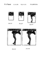
- FIG. 14 shows an example of an object for explaining the concept in this embodiment.
- a first tetrahedron 1402 that is inscribed inside an object 1401 is formed virtually.
- the coordinates of the vertex of the first tetrahedron 1402 represent vertex data of basic polygon data.
- the coordinates of the vertex of the first tetrahedron 1402 can be designated by the user with a 3D information editing tool, or can be computed automatically.
- progressive polygon data is generated by forming a new tetrahedron that shares one face with the first tetrahedron 1402 .
- FIG. 15 shows an example of how to form a tetrahedron whose base is one face 1403 of the first tetrahedron.
- the difference between the length L on the boundary and the length l of the line segment is compared with a predetermined value ⁇ .
- the object 1401 is segmented by a face formed by the shortest lines along the surface connecting the vertices of the tetrahedron. Then, a difference between a surface area of the segmented part of the object 1401 and an area of the corresponding face of the tetrahedron is compared with a predetermined value, so as to determine the level of hierarchy.
- the vertices of the face 1403 of the first tetrahedron are denoted by T, U and W.
- the shortest lines along the surface connecting the vertex D of the new tetrahedron and the vertices T and U are denoted by TD, DU and TU.
- a difference between a surface area of a portion on the object 1401 segmented by the face formed by the lines TD, DU and TU and an area of a triangle TDU is calculated.
- the difference between the surface area of the portion and the area of the triangle is below a predetermined value, it is determined that it is not necessary to form a new tetrahedron including the triangle TDU any more.
- the centroid of the triangle TDU is calculated so as to form a new tetrahedron with the same process as described above.
- the progressive polygon data can be obtained.
- the coordinates of the vertex D of the new tetrahedron are stored in the form of relative coordinates in the coordinate system defined by using the vertices T, D and U forming a face of the first tetrahedron, more specifically, by using a vector from the vertex T to the vertex D and a vector from the vertex T to the vertex U and an outer product of the vectors.
- FIG. 17 is a diagram for illustrating the relative coordinates of a new vertex in detail
- V 11 corresponds to the vertex T
- V 12 corresponds to the vertex W
- V 13 corresponds to the vertex U
- V 111 corresponds to the new vertex D.
- P 1 a vector from V 11 to V 12
- P 2 a vector from V 11 to V 13
- P 3 a vector from V 11 to V 13
- V 111 l 111 P 1 +m 111 P 2 +n 111 P 3 , where l, m and n are suitable real numbers.
- FIG. 18 is an example of a data structure of the progressive polygon data in this embodiment.
- the progressive polygon data in this embodiment is different from that in the first embodiment in the content of the detailed polygon vertex data 305 . This is because it is necessary to store three identifiers for three reference vertices in this embodiment.
- attributes of the vectors from the first vertex of the three vertices to the other two vertices and the outer products of the vectors are stored as 1 111 , m 111 and n 111 obtained in the above equation.
- the relative coordinates in the three dimensional coordinates are stored.
- the detailed polygon data is sequentially computed from the basic polygon data so as to generate progressive polygon data, so that 3D polygon data with a suitable number of polygons can be produced.
- a suitable 3D polygon data can be produced even when the basic polygon data 1061 is edited.
- FIG. 19 is a flow chart showing the process procedure of the controller 102 when generating progressive polygon data according to the method of this embodiment.
- an object is selected (S 1901 ), and the coordinates of the first tetrahedron as shown in FIG. 15 are determined with respect to the selected object (S 1902 ).
- the coordinates can be determined automatically by the controller 102 , or can be selected by the user.
- the difference between an area of each face of the tetrahedron and a surface area of a corresponding portion of the object is calculated and compared with a predetermined value (S 1903 ).
- a predetermined value When the difference is below the predetermined value with respect to all the faces of the tetrahedron (S 1903 : Yes), there is no need to further perform the polygon progressing process. Then, the next object is selected.
- the use of the progressive polygon data generated by the method for generating progressive polygon data as described above makes it possible to take any forms in accordance with the number of polygons that can be used for displaying on the screen and to reduce a storage area for polygon data.
- the use of the progressive polygon data generated by the methods of the present invention provides polygon data with a desired level of coarseness.
- An important issue is how to determine the number of polygons for rendering polygon data. If the number of polygons can be determined by system resources for rendering, the system resources for rendering are assigned as parameters, and the detailed polygon data is sequentially computed from the basic polygon data in accordance with the parameters. In this manner, polygon data with a desired level of coarseness can be obtained.
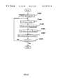
- FIG. 20 is a flow chart showing the process procedure of the controller 102 when calculating the number of polygons for rendering in the 3D real-time graphics generator in this embodiment. This process is performed by the rendering polygon number calculating part 1025 , based on the progressive polygon data or the like.
- the number of polygons for an object to be rendered is managed based on the performance of the machine, the distance from the user to the object in the virtual world displayed on the screen (hereinafter, referred to as “Z value”) and the speed of the movement of the object.
- the shape of the polygon is recognized distinctly unless the object is rendered with a large number of polygons.
- the rendered object is small, so that the detail shape of the polygon cannot be recognized by the user, even if the object is rendered with a small number of polygons.
- the number of polygons for rendering an object is changed dynamically depending on the Z value of the object, by using the progressive polygon data as described above. Thus, the procedures of the CPU and the board can be minimized.
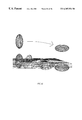
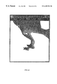
- FIGS. 21 to 25 show objects rendered with a variety of numbers of polygons, i.e., 10,000 polygons, 2,000 polygons, 400 polygons, 220 polygons, and 200 polygons, respectively. As shown in FIGS. 21 to 25 , as the number of polygons becomes smaller, the shape of the polygon can be recognized distinctly.
- FIGS. 26 to 30 show the same object as FIGS. 21 to 25 when viewed from above.
- FIGS. 31A to 31 E show downscaled rendering of the object according to the Z value (the Z value of the object in FIG. 31A is the largest).
- the rendered object of a large Z value looks natural, even though it is rendered with a small number of polygons.
- the 3D real-time graphics generator of the present invention produces polygon data progressively, polygon data that cannot be seen from the direction of the camera (viewpoint) can be calculated.
- a process of preventing polygons that cannot be seen from the camera from being rendered is performed.
- the edge of the object is conspicuous.
- the edge is rendered with a large number of polygons and the front of the object is rendered with a small number of polygons by referring to the relation between the direction of the camera and the normal line of the object, so that graphics with high quality can be rendered with a small number of polygons.
- the object can be rendered naturally with a small number of polygons.
- the object on the way of the movement can be rendered with a smaller number of polygons without giving any visual problem to the user.
- the controller 102 first acquires machine data (S 2001 ).
- Machine data refers to information concerning the function, performance, etc. of the computer. It is not necessary to change this value even when objects are changed, and it suffices to acquire the value only once at the beginning.
- the machine data can be acquired by various methods.
- the machine data can be assigned by the user as a parameter.
- a Z value is acquired for every object (S 2002 ), and position information of a centroid of the object for every frame stored in the progressive polygon data storage 106 is acquired (S 2003 ).
- the distance of the movement of the object for every frame i.e., the speed of the movement of the object, is calculated (S 2004 ).
- the number of polygons is determined (S 2005 ).
- the number of polygons is sent to the merging part 1026 in the form of the step number in the progressive polygon data, as described above. Therefore, the rendering polygon number calculating part 1025 in this embodiment stores a table indicating the correspondence between a specific number of polygons that are allowed to be used and the step number. However, such a table is not always necessary.
- the number of polygons can be sent to the merging part 1026 in the form of a ratio to the maximum number.
- the steps S 2002 to S 2005 are performed for every object and when all the objects have been subjected to the process of this embodiment, the whole process is complete (S 2006 ).
- the use of the 3D real-time graphics generator makes it possible to render an object with a number of polygons suitable for the system resources for rendering.
- the progressive polygon data generated according to the present invention includes the basic polygon data 1061 representing an object with the smallest number of polygons and the detailed polygon data 1062 representing vertices of polyhedrons that are sequentially computed starting from the basic polygon data 1061 .
- the detailed polygon data 1062 is used to approximate the shape of the object represented by the basic polygon data 1061 to the shape of the object represented by the original polygon data.
- the detailed polygon data 1062 is represented by relative coordinates, as described above. Therefore, for example, the basic polygon data 1061 is changed via the basic polygon data editing part 1024 so as to transform an object, and then the detailed polygon data is sequentially computed from the changed basic polygon data representing the transformed object, so that the entire object can be transformed.
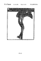
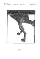
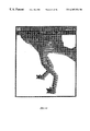
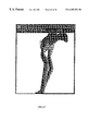
- FIG. 33 shows an example of a object whose progressive polygon data has been obtained according to the method for generating progressive polygon data of the present invention.
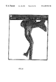
- this object is rendered with only the basic polygon data 1061 , the representation is coarse, as seen in FIG. 34 where the left leg is formed as a triangle.
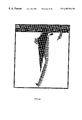
- FIG. 35 is a view showing the entire object that has moved to right. In this example, the object has been moved to right by 10% of the horizontal axis.
- the basic polygon data of the edited object is stored in the form of absolute coordinates in the progressive polygon data storage 106 separately from the basic polygon data before editing.
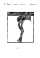
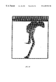
- the merging part 1026 sequentially computes the detailed polygon data 1062 starting from the basic polygon data. In this manner, the entire object can be translated, as shown in FIG. 36 .
- FIGS. 37 to 40 are views showing the object shown in FIGS. 33 to 36 that is subjected to the same process when viewed from above.
- the object has been translated directly from one position to another.
- an object positioned between the two positions shown in the example of this embodiment can be produced and can be rendered at every predetermined time, so that animation where the object is moving gradually can be produced.
- information about timing at which objects are rendered is added to the progressive polygon data representing animation via the basic polygon data editing part 1024 , so that the merging part 1026 and the 3D information rendering part 1027 perform the process to render the object at the timing specified by the information.
- animation can be rendered.
- the use of the 3D real-time graphics generator of this embodiment facilitates editing of an object.
- the use of the progressive polygon data of the present invention makes it possible for a computer to perform the process at high speed, because the computer has only to compute the amount of data of order (n) in the sequential computation for the detailed polygon data. That is, even if the complexity of a problem increases by n times, the amount of data for the computation increases only by n times.
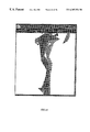
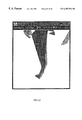
- FIG. 41 shows an example of a object whose progressive polygon data has been obtained according to the method for generating progressive polygon data of the present invention.
- this object is rendered with only the basic polygon data 1061 , the representation is coarse, as seen in FIG. 42 where the left leg is formed as a triangle.
- FIG. 43 is a view showing the shape of the polygon mesh that has been transformed due to the change.
- FIGS. 45 to 48 are views showing the objects that are subjected to the same process as FIGS. 41 to 44 when viewed from below on the left side.
- the object has changed directly from one shape to another shape.
- objects with shapes on the way of the change between the two shapes shown in the example of this embodiment can be produced and can be rendered at every predetermined time, so that animation where the object is gradually lifting its left leg can be produced, as in the case of Embodiment 4.
- the use of the 3D real-time graphics generator of this embodiment facilitates editing of an object.
- the use of the progressive polygon data of the present invention makes it possible for a computer to perform the process at high speed, because the computer has only to compute the amount of data of order (n) in the sequential computation for the detailed polygon data. That is, even if the complexity of a problem increases by n times, the amount of data for the computation increases only by n times.
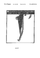
- FIG. 49 shows an example of a object whose progressive polygon data has been obtained according to the method for generating progressive polygon data of the present invention.
- this object is rendered with only the basic polygon data 1061 , the representation is coarse, as seen in FIG. 50 where the left leg is formed as a triangle.
- FIG. 51 is a view showing the shape of the polygon mesh that has been transformed due to the change.
- FIGS. 53 to 56 are views showing the objects that are subjected to the same process as FIGS. 49 to 52 when viewed from above.
- the object has changed directly from one shape to another shape.
- a plurality of objects with shapes on the way of the change between the two shapes shown in the example of this embodiment can be produced and can be rendered at every predetermined time, so that animation where the left leg is gradually swollen can be produced, as in the case of Embodiment 4.
- the method for generating progressive polygon data the method of virtually bisecting a 3D object and the method of approximating a tetrahedron to the shape of the object progressively have been described.
- the effect of the present invention can be obtained when progressively detailed vertices are obtained and information about the positions of the obtained detailed vertices are stored in the form of relative coordinates. Methods for realizing the effect of the present invention are not limited to the methods that have been described above.
- a recording medium in which programs for realizing the progressive polygon data generator and the 3D real-time graphics generator of the present invention are recorded can be not only a transportable recording medium 572 such as a CD-ROM 572 - 1 , or a floppy disk 572 - 2 , but also a remote accessible storage apparatus 571 or an equipped storage medium such as a hard disk and a RAM of a computer.
- the program 574 is loaded into the main memory of a data processing apparatus, and executed.
- a recording medium storing the progressive polygon data generated according to the apparatus or the method for generating the progressive polygon data of the present invention can be not only a transportable recording medium 572 such as a CD-ROM 572 - 1 , or a floppy disk 572 - 2 , but also a remote storage apparatus 571 or an equipped storage medium such as a hard disk and a RAM of a computer.
- the recording medium can be read by a computer when the 3D real-time graphics generator of the present invention is utilized.
- the use of the apparatus and method for generating the progressive polygon data of the present invention makes it possible to deal with any number of rendering polygons, so that 3D polygon data that can be utilized for general purposes by machines with various performances can be generated. Moreover, since the detailed polygon data is generated progressively, it is possible to reduce a storage area for 3D polygon data.
- the use of the progressive polygon data generated according to the present invention makes it possible to reduce the amount of data processed by the computer so that the computer can process data at high speed.
- the use of the apparatus and method for generating the 3D real-time graphics facilitates editing of objects so that the amount of work of an animator can be reduced.
Abstract
Description
Claims (48)
Applications Claiming Priority (2)
| Application Number | Priority Date | Filing Date | Title |
|---|---|---|---|
| JP9-351310 | 1997-12-19 | ||
| JP35131097A JP3654616B2 (en) | 1997-12-19 | 1997-12-19 | Hierarchical polygon data generation apparatus and method, and three-dimensional real-time video generation apparatus and method using the hierarchical polygon data |
Publications (1)
| Publication Number | Publication Date |
|---|---|
| US6307554B1 true US6307554B1 (en) | 2001-10-23 |
Family
ID=18416448
Family Applications (1)
| Application Number | Title | Priority Date | Filing Date |
|---|---|---|---|
| US09/071,830 Expired - Lifetime US6307554B1 (en) | 1997-12-19 | 1998-05-04 | Apparatus and method for generating progressive polygon data, and apparatus and method for generating three-dimensional real-time graphics using the same |
Country Status (3)
| Country | Link |
|---|---|
| US (1) | US6307554B1 (en) |
| EP (1) | EP0926628A3 (en) |
| JP (1) | JP3654616B2 (en) |
Cited By (30)
| Publication number | Priority date | Publication date | Assignee | Title |
|---|---|---|---|---|
| US20010010522A1 (en) * | 2000-01-27 | 2001-08-02 | Mitsubishi Denki Kabushiki Kaisha | Three-dimensional graphic processing device for drawing polygon having vertex data defined by relative value and method therefor |
| US20030007678A1 (en) * | 2001-07-06 | 2003-01-09 | Keizo Ohta | Image processing apparatus and program for displaying object shapes |
| US20040017369A1 (en) * | 2002-01-22 | 2004-01-29 | Hultgren Bruce Willard | Method and apparatus for computer generation of electronic model images |
| WO2004075110A2 (en) * | 2003-02-20 | 2004-09-02 | Binary Simplex, Inc. | Image display, manipulation, and spatial decomposition methods |
| US20050024362A1 (en) * | 2001-07-11 | 2005-02-03 | Klein Dean A. | Three dimensional rendering including motion sorting |
| US20100118029A1 (en) * | 2007-03-15 | 2010-05-13 | Basimah Khulusi | Apparatus And Method For Modeling All Matter By Modeling, Truncating, And Creating N-Dimensional Polyhedra Including Those Having Holes, Concave Attributes, And No Symmetry |
| US20110131491A1 (en) * | 2009-11-30 | 2011-06-02 | International Business Machines Corporation | Dynamic help information |
| US8436860B1 (en) * | 2006-06-09 | 2013-05-07 | Pixar | Techniques for using depth maps |
| US8497860B2 (en) | 2003-02-20 | 2013-07-30 | Binary Simplex, Inc. | Spatial decomposition methods using bit manipulation |
| US8508535B1 (en) | 2006-06-09 | 2013-08-13 | Pixar | Systems and methods for locking inverse kinematic (IK) objects to a surface object |
| US20140058959A1 (en) * | 2012-08-21 | 2014-02-27 | Kimmo Isbjornssund | Method and system for enforcing 3d restricted rights in a rapid manufacturing and prototyping environment |
| US8757485B2 (en) | 2012-09-05 | 2014-06-24 | Greatbatch Ltd. | System and method for using clinician programmer and clinician programming data for inventory and manufacturing prediction and control |
| US8761897B2 (en) | 2012-08-31 | 2014-06-24 | Greatbatch Ltd. | Method and system of graphical representation of lead connector block and implantable pulse generators on a clinician programmer |
| US8812125B2 (en) | 2012-08-31 | 2014-08-19 | Greatbatch Ltd. | Systems and methods for the identification and association of medical devices |
| US8868199B2 (en) | 2012-08-31 | 2014-10-21 | Greatbatch Ltd. | System and method of compressing medical maps for pulse generator or database storage |
| US8903496B2 (en) | 2012-08-31 | 2014-12-02 | Greatbatch Ltd. | Clinician programming system and method |
| US8983616B2 (en) | 2012-09-05 | 2015-03-17 | Greatbatch Ltd. | Method and system for associating patient records with pulse generators |
| US9183295B2 (en) | 2012-10-17 | 2015-11-10 | Thomson Licensing | Method and apparatus for retrieving a media file of interest |
| US9180302B2 (en) | 2012-08-31 | 2015-11-10 | Greatbatch Ltd. | Touch screen finger position indicator for a spinal cord stimulation programming device |
| US9259577B2 (en) | 2012-08-31 | 2016-02-16 | Greatbatch Ltd. | Method and system of quick neurostimulation electrode configuration and positioning |
| US9375582B2 (en) | 2012-08-31 | 2016-06-28 | Nuvectra Corporation | Touch screen safety controls for clinician programmer |
| US9378575B1 (en) | 2013-11-05 | 2016-06-28 | Pixar | Chained kinematic logic |
| US9471753B2 (en) | 2012-08-31 | 2016-10-18 | Nuvectra Corporation | Programming and virtual reality representation of stimulation parameter Groups |
| US9507912B2 (en) | 2012-08-31 | 2016-11-29 | Nuvectra Corporation | Method and system of simulating a pulse generator on a clinician programmer |
| US9594877B2 (en) | 2012-08-31 | 2017-03-14 | Nuvectra Corporation | Virtual reality representation of medical devices |
| US9615788B2 (en) | 2012-08-31 | 2017-04-11 | Nuvectra Corporation | Method and system of producing 2D representations of 3D pain and stimulation maps and implant models on a clinician programmer |
| US9767255B2 (en) | 2012-09-05 | 2017-09-19 | Nuvectra Corporation | Predefined input for clinician programmer data entry |
| US10325373B2 (en) | 2017-09-07 | 2019-06-18 | Here Global B.V. | Method, apparatus, and system for constructing a polygon from edges for object detection |
| RU2706460C1 (en) * | 2016-07-12 | 2019-11-19 | Шангвен КАО | Method of performing high-speed boolean operations by means of geometrical faces |
| US10668276B2 (en) | 2012-08-31 | 2020-06-02 | Cirtec Medical Corp. | Method and system of bracketing stimulation parameters on clinician programmers |
Families Citing this family (6)
| Publication number | Priority date | Publication date | Assignee | Title |
|---|---|---|---|---|
| US6625509B1 (en) | 1999-03-05 | 2003-09-23 | R & F Industries, Llc | Automated multisection rail material list generation system and method |
| US7127081B1 (en) | 2000-10-12 | 2006-10-24 | Momentum Bilgisayar, Yazilim, Danismanlik, Ticaret, A.S. | Method for tracking motion of a face |
| US6731287B1 (en) * | 2000-10-12 | 2004-05-04 | Momentum Bilgisayar, Yazilim, Danismanlik, Ticaret A.S. | Method for animating a 3-D model of a face |
| US6664956B1 (en) * | 2000-10-12 | 2003-12-16 | Momentum Bilgisayar, Yazilim, Danismanlik, Ticaret A. S. | Method for generating a personalized 3-D face model |
| JP3961525B2 (en) * | 2004-09-22 | 2007-08-22 | 株式会社コナミデジタルエンタテインメント | Image processing apparatus, image processing method, and program |
| JP5919111B2 (en) * | 2012-06-28 | 2016-05-18 | 株式会社Nttファシリティーズ | Outline data generation apparatus, outline data generation method and program |
Citations (11)
| Publication number | Priority date | Publication date | Assignee | Title |
|---|---|---|---|---|
| US5123084A (en) * | 1987-12-24 | 1992-06-16 | General Electric Cgr S.A. | Method for the 3d display of octree-encoded objects and device for the application of this method |
| US5301267A (en) * | 1991-09-27 | 1994-04-05 | Adobe Systems Incorporated | Intelligent font rendering co-processor |
| US5349533A (en) * | 1992-05-08 | 1994-09-20 | Lockheed Missiles & Space Company, Inc. | System and method for collision checking between solid objects and vectors |
| JPH0785307A (en) | 1993-09-17 | 1995-03-31 | Canon Inc | Method and device for displaying three-dimensional picture |
| US5712964A (en) * | 1993-09-29 | 1998-01-27 | Fujitsu Limited | Computer graphics data display device and method based on a high-speed generation of a changed image |
| US5771341A (en) * | 1992-11-06 | 1998-06-23 | Canon Kabushiki Kaisha | Graphics apparatus and method for dividing parametric surface patches defining an object into polygons |
| US5929860A (en) * | 1996-01-11 | 1999-07-27 | Microsoft Corporation | Mesh simplification and construction of progressive meshes |
| US5936869A (en) * | 1995-05-25 | 1999-08-10 | Matsushita Electric Industrial Co., Ltd. | Method and device for generating mesh for use in numerical analysis |
| US5943056A (en) * | 1995-07-11 | 1999-08-24 | Fujitsu Ltd. | Interference checking method |
| US5947819A (en) * | 1996-05-22 | 1999-09-07 | Konami Co., Ltd. | Object-throwing video game system |
| US5999185A (en) * | 1992-03-30 | 1999-12-07 | Kabushiki Kaisha Toshiba | Virtual reality control using image, model and control data to manipulate interactions |
-
1997
- 1997-12-19 JP JP35131097A patent/JP3654616B2/en not_active Expired - Fee Related
-
1998
- 1998-04-30 EP EP98303404A patent/EP0926628A3/en not_active Withdrawn
- 1998-05-04 US US09/071,830 patent/US6307554B1/en not_active Expired - Lifetime
Patent Citations (11)
| Publication number | Priority date | Publication date | Assignee | Title |
|---|---|---|---|---|
| US5123084A (en) * | 1987-12-24 | 1992-06-16 | General Electric Cgr S.A. | Method for the 3d display of octree-encoded objects and device for the application of this method |
| US5301267A (en) * | 1991-09-27 | 1994-04-05 | Adobe Systems Incorporated | Intelligent font rendering co-processor |
| US5999185A (en) * | 1992-03-30 | 1999-12-07 | Kabushiki Kaisha Toshiba | Virtual reality control using image, model and control data to manipulate interactions |
| US5349533A (en) * | 1992-05-08 | 1994-09-20 | Lockheed Missiles & Space Company, Inc. | System and method for collision checking between solid objects and vectors |
| US5771341A (en) * | 1992-11-06 | 1998-06-23 | Canon Kabushiki Kaisha | Graphics apparatus and method for dividing parametric surface patches defining an object into polygons |
| JPH0785307A (en) | 1993-09-17 | 1995-03-31 | Canon Inc | Method and device for displaying three-dimensional picture |
| US5712964A (en) * | 1993-09-29 | 1998-01-27 | Fujitsu Limited | Computer graphics data display device and method based on a high-speed generation of a changed image |
| US5936869A (en) * | 1995-05-25 | 1999-08-10 | Matsushita Electric Industrial Co., Ltd. | Method and device for generating mesh for use in numerical analysis |
| US5943056A (en) * | 1995-07-11 | 1999-08-24 | Fujitsu Ltd. | Interference checking method |
| US5929860A (en) * | 1996-01-11 | 1999-07-27 | Microsoft Corporation | Mesh simplification and construction of progressive meshes |
| US5947819A (en) * | 1996-05-22 | 1999-09-07 | Konami Co., Ltd. | Object-throwing video game system |
Cited By (46)
| Publication number | Priority date | Publication date | Assignee | Title |
|---|---|---|---|---|
| US6788299B2 (en) * | 2000-01-27 | 2004-09-07 | Renesas Technology Corp. | Three-dimensional graphic processing device for drawing polygon having vertex data defined by relative value and method therefor |
| US20010010522A1 (en) * | 2000-01-27 | 2001-08-02 | Mitsubishi Denki Kabushiki Kaisha | Three-dimensional graphic processing device for drawing polygon having vertex data defined by relative value and method therefor |
| US20030007678A1 (en) * | 2001-07-06 | 2003-01-09 | Keizo Ohta | Image processing apparatus and program for displaying object shapes |
| US6897859B2 (en) * | 2001-07-06 | 2005-05-24 | Nintendo Co., Ltd. | Image processing apparatus for polyhedron shaped objects |
| US7038679B2 (en) | 2001-07-11 | 2006-05-02 | Micron Technology, Inc. | Three dimensional rendering including motion sorting |
| US20050024362A1 (en) * | 2001-07-11 | 2005-02-03 | Klein Dean A. | Three dimensional rendering including motion sorting |
| US20060262128A1 (en) * | 2001-07-11 | 2006-11-23 | Klein Dean A | Three dimensional rendering including motion sorting |
| US20040017369A1 (en) * | 2002-01-22 | 2004-01-29 | Hultgren Bruce Willard | Method and apparatus for computer generation of electronic model images |
| US7777740B2 (en) | 2003-02-20 | 2010-08-17 | Binary Simplex, Inc. | Spatial decomposition methods using bit manipulation |
| WO2004075110A2 (en) * | 2003-02-20 | 2004-09-02 | Binary Simplex, Inc. | Image display, manipulation, and spatial decomposition methods |
| WO2004075110A3 (en) * | 2003-02-20 | 2005-05-12 | Binary Simplex Inc | Image display, manipulation, and spatial decomposition methods |
| US8497860B2 (en) | 2003-02-20 | 2013-07-30 | Binary Simplex, Inc. | Spatial decomposition methods using bit manipulation |
| US8436860B1 (en) * | 2006-06-09 | 2013-05-07 | Pixar | Techniques for using depth maps |
| US8508535B1 (en) | 2006-06-09 | 2013-08-13 | Pixar | Systems and methods for locking inverse kinematic (IK) objects to a surface object |
| US20100118029A1 (en) * | 2007-03-15 | 2010-05-13 | Basimah Khulusi | Apparatus And Method For Modeling All Matter By Modeling, Truncating, And Creating N-Dimensional Polyhedra Including Those Having Holes, Concave Attributes, And No Symmetry |
| US8599195B2 (en) * | 2007-03-15 | 2013-12-03 | Basimah Khulusi | Apparatus and method for modeling all matter by modeling, truncating, and creating N-dimensional polyhedra including those having holes, concave attributes, and no symmetry |
| US20110131491A1 (en) * | 2009-11-30 | 2011-06-02 | International Business Machines Corporation | Dynamic help information |
| US9026910B2 (en) | 2009-11-30 | 2015-05-05 | International Business Machines Corporation | Dynamic help information |
| US20140058959A1 (en) * | 2012-08-21 | 2014-02-27 | Kimmo Isbjornssund | Method and system for enforcing 3d restricted rights in a rapid manufacturing and prototyping environment |
| US8903496B2 (en) | 2012-08-31 | 2014-12-02 | Greatbatch Ltd. | Clinician programming system and method |
| US9507912B2 (en) | 2012-08-31 | 2016-11-29 | Nuvectra Corporation | Method and system of simulating a pulse generator on a clinician programmer |
| US8868199B2 (en) | 2012-08-31 | 2014-10-21 | Greatbatch Ltd. | System and method of compressing medical maps for pulse generator or database storage |
| US8761897B2 (en) | 2012-08-31 | 2014-06-24 | Greatbatch Ltd. | Method and system of graphical representation of lead connector block and implantable pulse generators on a clinician programmer |
| US10668276B2 (en) | 2012-08-31 | 2020-06-02 | Cirtec Medical Corp. | Method and system of bracketing stimulation parameters on clinician programmers |
| US10376701B2 (en) | 2012-08-31 | 2019-08-13 | Nuvectra Corporation | Touch screen safety controls for clinician programmer |
| US10347381B2 (en) | 2012-08-31 | 2019-07-09 | Nuvectra Corporation | Programming and virtual reality representation of stimulation parameter groups |
| US9180302B2 (en) | 2012-08-31 | 2015-11-10 | Greatbatch Ltd. | Touch screen finger position indicator for a spinal cord stimulation programming device |
| US9259577B2 (en) | 2012-08-31 | 2016-02-16 | Greatbatch Ltd. | Method and system of quick neurostimulation electrode configuration and positioning |
| US9314640B2 (en) | 2012-08-31 | 2016-04-19 | Greatbatch Ltd. | Touch screen finger position indicator for a spinal cord stimulation programming device |
| US9375582B2 (en) | 2012-08-31 | 2016-06-28 | Nuvectra Corporation | Touch screen safety controls for clinician programmer |
| US10141076B2 (en) | 2012-08-31 | 2018-11-27 | Nuvectra Corporation | Programming and virtual reality representation of stimulation parameter groups |
| US9471753B2 (en) | 2012-08-31 | 2016-10-18 | Nuvectra Corporation | Programming and virtual reality representation of stimulation parameter Groups |
| US8812125B2 (en) | 2012-08-31 | 2014-08-19 | Greatbatch Ltd. | Systems and methods for the identification and association of medical devices |
| US9555255B2 (en) | 2012-08-31 | 2017-01-31 | Nuvectra Corporation | Touch screen finger position indicator for a spinal cord stimulation programming device |
| US9594877B2 (en) | 2012-08-31 | 2017-03-14 | Nuvectra Corporation | Virtual reality representation of medical devices |
| US9615788B2 (en) | 2012-08-31 | 2017-04-11 | Nuvectra Corporation | Method and system of producing 2D representations of 3D pain and stimulation maps and implant models on a clinician programmer |
| US10083261B2 (en) | 2012-08-31 | 2018-09-25 | Nuvectra Corporation | Method and system of simulating a pulse generator on a clinician programmer |
| US9776007B2 (en) | 2012-08-31 | 2017-10-03 | Nuvectra Corporation | Method and system of quick neurostimulation electrode configuration and positioning |
| US9901740B2 (en) | 2012-08-31 | 2018-02-27 | Nuvectra Corporation | Clinician programming system and method |
| US9767255B2 (en) | 2012-09-05 | 2017-09-19 | Nuvectra Corporation | Predefined input for clinician programmer data entry |
| US8757485B2 (en) | 2012-09-05 | 2014-06-24 | Greatbatch Ltd. | System and method for using clinician programmer and clinician programming data for inventory and manufacturing prediction and control |
| US8983616B2 (en) | 2012-09-05 | 2015-03-17 | Greatbatch Ltd. | Method and system for associating patient records with pulse generators |
| US9183295B2 (en) | 2012-10-17 | 2015-11-10 | Thomson Licensing | Method and apparatus for retrieving a media file of interest |
| US9378575B1 (en) | 2013-11-05 | 2016-06-28 | Pixar | Chained kinematic logic |
| RU2706460C1 (en) * | 2016-07-12 | 2019-11-19 | Шангвен КАО | Method of performing high-speed boolean operations by means of geometrical faces |
| US10325373B2 (en) | 2017-09-07 | 2019-06-18 | Here Global B.V. | Method, apparatus, and system for constructing a polygon from edges for object detection |
Also Published As
| Publication number | Publication date |
|---|---|
| EP0926628A3 (en) | 2003-11-12 |
| EP0926628A2 (en) | 1999-06-30 |
| JP3654616B2 (en) | 2005-06-02 |
| JPH11185060A (en) | 1999-07-09 |
Similar Documents
| Publication | Publication Date | Title |
|---|---|---|
| US6307554B1 (en) | Apparatus and method for generating progressive polygon data, and apparatus and method for generating three-dimensional real-time graphics using the same | |
| Perry et al. | Kizamu: A system for sculpting digital characters | |
| US8154544B1 (en) | User specified contact deformations for computer graphics | |
| JP3380231B2 (en) | 3D skeleton data compression device | |
| US7983882B1 (en) | Joint wrinkle and muscle movement simulating software | |
| US7038679B2 (en) | Three dimensional rendering including motion sorting | |
| US7236170B2 (en) | Wrap deformation using subdivision surfaces | |
| US7348976B2 (en) | Three-dimensional shape display program, three-dimensional shape display method, and three-dimensional shape display apparatus | |
| JP4842242B2 (en) | Method and apparatus for real-time expression of skin wrinkles during character animation | |
| US7333112B2 (en) | Rig baking | |
| JP4463597B2 (en) | 3D drawing model generation method and program thereof | |
| JP2837584B2 (en) | How to create terrain data | |
| WO2003017206A1 (en) | Automatic 3d modeling system and method | |
| US9734616B1 (en) | Tetrahedral volumes from segmented bounding boxes of a subdivision | |
| Sturzlinger | Ray-tracing triangular trimmed free-form surfaces | |
| US10636210B2 (en) | Dynamic contour volume deformation | |
| US8669980B1 (en) | Procedural methods for editing hierarchical subdivision surface geometry | |
| US11727616B2 (en) | Contour lines for volumetric objects | |
| Bendels et al. | Image and 3D-Object Editing with Precisely Specified Editing Regions. | |
| KR100512567B1 (en) | Displaced Subdivision Mesh restoration method for face animation | |
| JP3711273B2 (en) | 3D graphics drawing device for occlusion culling | |
| JPH10172009A (en) | Method and device for generating three-dimensional cg animation | |
| JPH07220118A (en) | Topographic display device | |
| CN116797696A (en) | Skeleton driving method and device for character animation | |
| Mari | Automatic surface generation with a voxel-based skeleton defining topological constraints |
Legal Events
| Date | Code | Title | Description |
|---|---|---|---|
| AS | Assignment |
Owner name: FUJITSU LIMITED, JAPAN Free format text: ASSIGNMENT OF ASSIGNORS INTEREST;ASSIGNORS:ARAI, MASATOSHI;MIYATA, RYOSUKE;MURAKAMI, KOICHI;REEL/FRAME:009216/0796 Effective date: 19980423 |
|
| STCF | Information on status: patent grant |
Free format text: PATENTED CASE |
|
| FPAY | Fee payment |
Year of fee payment: 4 |
|
| FPAY | Fee payment |
Year of fee payment: 8 |
|
| FEPP | Fee payment procedure |
Free format text: PAYER NUMBER DE-ASSIGNED (ORIGINAL EVENT CODE: RMPN); ENTITY STATUS OF PATENT OWNER: LARGE ENTITY Free format text: PAYOR NUMBER ASSIGNED (ORIGINAL EVENT CODE: ASPN); ENTITY STATUS OF PATENT OWNER: LARGE ENTITY |
|
| AS | Assignment |
Owner name: LD TECHNOLOGIES, LLC, DELAWARE Free format text: ASSIGNMENT OF ASSIGNORS INTEREST;ASSIGNOR:FUJITSU LIMITED;REEL/FRAME:026459/0350 Effective date: 20110331 |
|
| FPAY | Fee payment |
Year of fee payment: 12 |
|
| AS | Assignment |
Owner name: HANGER SOLUTIONS, LLC, GEORGIA Free format text: ASSIGNMENT OF ASSIGNORS INTEREST;ASSIGNOR:INTELLECTUAL VENTURES ASSETS 158 LLC;REEL/FRAME:051486/0425 Effective date: 20191206 |
|
| AS | Assignment |
Owner name: INTELLECTUAL VENTURES ASSETS 158 LLC, DELAWARE Free format text: ASSIGNMENT OF ASSIGNORS INTEREST;ASSIGNOR:LD TECHNOLOGIES, LLC;REEL/FRAME:051777/0163 Effective date: 20191126 |