US6303074B1 - Mixed flow rotor for molten metal pumping device - Google Patents
Mixed flow rotor for molten metal pumping device Download PDFInfo
- Publication number
- US6303074B1 US6303074B1 US09/312,361 US31236199A US6303074B1 US 6303074 B1 US6303074 B1 US 6303074B1 US 31236199 A US31236199 A US 31236199A US 6303074 B1 US6303074 B1 US 6303074B1
- Authority
- US
- United States
- Prior art keywords
- rotor
- molten metal
- pump
- pump chamber
- chamber
- Prior art date
- Legal status (The legal status is an assumption and is not a legal conclusion. Google has not performed a legal analysis and makes no representation as to the accuracy of the status listed.)
- Expired - Lifetime
Links
Images


Classifications
-
- C—CHEMISTRY; METALLURGY
- C22—METALLURGY; FERROUS OR NON-FERROUS ALLOYS; TREATMENT OF ALLOYS OR NON-FERROUS METALS
- C22B—PRODUCTION AND REFINING OF METALS; PRETREATMENT OF RAW MATERIALS
- C22B9/00—General processes of refining or remelting of metals; Apparatus for electroslag or arc remelting of metals
- C22B9/05—Refining by treating with gases, e.g. gas flushing also refining by means of a material generating gas in situ
-
- C—CHEMISTRY; METALLURGY
- C22—METALLURGY; FERROUS OR NON-FERROUS ALLOYS; TREATMENT OF ALLOYS OR NON-FERROUS METALS
- C22B—PRODUCTION AND REFINING OF METALS; PRETREATMENT OF RAW MATERIALS
- C22B21/00—Obtaining aluminium
- C22B21/0084—Obtaining aluminium melting and handling molten aluminium
- C22B21/0092—Remelting scrap, skimmings or any secondary source aluminium
-
- F—MECHANICAL ENGINEERING; LIGHTING; HEATING; WEAPONS; BLASTING
- F27—FURNACES; KILNS; OVENS; RETORTS
- F27D—DETAILS OR ACCESSORIES OF FURNACES, KILNS, OVENS, OR RETORTS, IN SO FAR AS THEY ARE OF KINDS OCCURRING IN MORE THAN ONE KIND OF FURNACE
- F27D3/00—Charging; Discharging; Manipulation of charge
- F27D3/14—Charging or discharging liquid or molten material
-
- F—MECHANICAL ENGINEERING; LIGHTING; HEATING; WEAPONS; BLASTING
- F27—FURNACES; KILNS; OVENS; RETORTS
- F27D—DETAILS OR ACCESSORIES OF FURNACES, KILNS, OVENS, OR RETORTS, IN SO FAR AS THEY ARE OF KINDS OCCURRING IN MORE THAN ONE KIND OF FURNACE
- F27D3/00—Charging; Discharging; Manipulation of charge
- F27D2003/0034—Means for moving, conveying, transporting the charge in the furnace or in the charging facilities
- F27D2003/0054—Means to move molten metal, e.g. electromagnetic pump
-
- Y—GENERAL TAGGING OF NEW TECHNOLOGICAL DEVELOPMENTS; GENERAL TAGGING OF CROSS-SECTIONAL TECHNOLOGIES SPANNING OVER SEVERAL SECTIONS OF THE IPC; TECHNICAL SUBJECTS COVERED BY FORMER USPC CROSS-REFERENCE ART COLLECTIONS [XRACs] AND DIGESTS
- Y02—TECHNOLOGIES OR APPLICATIONS FOR MITIGATION OR ADAPTATION AGAINST CLIMATE CHANGE
- Y02P—CLIMATE CHANGE MITIGATION TECHNOLOGIES IN THE PRODUCTION OR PROCESSING OF GOODS
- Y02P10/00—Technologies related to metal processing
- Y02P10/20—Recycling
Definitions
- the present invention relates to a device for pumping molten metal wherein the device includes a rotor that directs flow both into and out of a pump chamber.
- Circulation pumps are used to circulate the molten metal within a bath, thereby equalizing the temperature of the molten metal and creating a uniformly consistent alloy.
- circulation pumps are used in conjunction with a reverbatory furnace having an external well. The well is usually an extension of the charging well where scrap metal is charged (i.e., added).
- Transfer pumps are generally used to transfer molten metal from the external well of the furnace to a different location such as a ladle or another furnace.
- Pumps including gas-release devices circulate the molten metal while adding a gas into the molten metal stream created by the pump in order to “demag” or “degas” the molten metal.
- a gas such as hydrogen, or dissolved metals such as magnesium.
- the removing of dissolved gas is known as “degassing” while the removal of magnesium is known as “demagging.”
- Known molten-metal pumps include a pump base that comprises a housing, also called a casing, a pump chamber, which is an open area (or cavity) formed within the housing, and a discharge, which is a channel formed within the housing that communicates with the chamber and leads from the chamber to an outlet formed in an exterior wall of the housing.
- a rotor also called an impeller, is mounted in the pump chamber and connected to a drive system, which is typically one or more vertical shafts that eventually connect to a motor. As the drive system turns the rotor, the rotor creates a stream of molten metal by pushing molten metal out of the pump chamber, through the discharge, out of the outlet and into the molten metal bath.
- molten metal pumping device When pumping molten metal it is desirable to increase the quantity of metal moved (or pumped) for each revolution of the rotor. Further, it is most desirable to increase the quantity of metal pumped per revolution without increasing the pump's size or energy consumption (or increasing the size and energy consumption by the minimum amount possible).
- Increasing the amount of molten metal pumped is desirable in any molten metal pumping device because it provides at least the following benefits: (1) in a circulation pump the temperature of the bath is more uniform; (2) in a gas-release pump more molten metal is demagged and/or degassed within a given time frame; and (3) in a transfer pump greater pressure is generated to push the molten metal upward to a higher elevation, if so desired.
- denser metals such as zinc, can be pumped through the same transfer pump, having relatively standard pump components and relatively low energy consumption, as is used to pump molten aluminum.
- the present invention solves these and other problems by providing a dual-flow (or mixed flow) rotor for a molten metal pumping device wherein the device comprises: (1) a pump housing including a pump chamber and a chamber wall, (2) a discharge leading from the chamber to an outlet that opens into a molten metal bath, (3) a rotor positioned in the chamber, and (4) a drive system for rotating the rotor about an axis.
- Dual-flow means that the rotor both directs molten metal into the pump chamber and outward toward the chamber wall where it ultimately passes through the discharge.
- the dual-flow rotor of the present invention preferably has a plurality of vanes wherein each vane comprises: (1) a first surface to direct molten metal into the pump chamber, and (2) a second surface for directing molten metal outward against the chamber wall.
- Each vane includes a horizontally-oriented projection that includes a leading edge, an upper surface and a lower surface.
- the first surface is preferably an angled wall formed in the lower surface of the projection near the leading edge.
- the second surface is preferably a substantially vertical face beneath the projection that directs the molten metal towards the chamber wall.
- Each vane includes a trailing side (opposite the first surface and second surface) that preferably includes a recess.
- the recess further increases the efficiency of the rotor (and a pump including the rotor) because the recess allows more molten metal to enter the pump chamber.
- a rotor of the present invention could also be used with a scrap melter, such as the type described in U.S. Pat. No. 5,308,045 to Cooper, the disclosure of which is incorporated herein by reference.
- the benefit of the rotor of the present invention, when used with a scrap metal, is that it (1) pushes the molten metal (and hence the scrap) downward into the bath, thereby facilitating the melting of the scrap, and (2) generates a greater flow of molten metal throughout the bath thereby keeping the temperature of the bath consistent, which also facilitates the melting of the scrap.
- FIG. 1 is a front, partial-sectional view of a molten metal pump in accordance with the invention having a pump discharge formed in the side of the pump housing.
- FIG. 1 a is a partial, cross-sectional view of the pump chamber shown in FIG. 1 with a rotor therein.
- FIG. 2 is a perspective, front view of a rotor in accordance with the present invention.
- FIG. 3 is a side view of the rotor of FIG. 2 .
- FIG. 4 is a top view of the rotor of FIG. 2 .
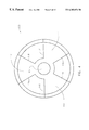
- FIG. 5 is a bottom view of the rotor of FIG. 2 .
- FIG. 6 is a perspective view of a dual-flow rotor according to the invention for use in a pump having an inlet in the top surface of the pump base and an inlet in the bottom surface of the pump base.
- FIG. 6 a is a front, partial cross-sectional view of a pump that includes two inlets, one in the top surface of the pump base and one in the bottom surface of the pump base, and that includes the rotor of FIG. 6 .
- FIG. 7 is a cut-away view of a well containing molten metal with a perspective view of a scrap melter according to the invention.
- FIG. 8 is a perspective view of the rotor shown in FIG. 7 .
- FIG. 1 shows a pumping device 10 submerged in a metallic bath B.
- Device 10 has a superstructure 20 and a base (or casing) 50 .
- Superstructure 20 is positioned outside of bath B when device 10 is operating and generally comprises a mounting plate 24 that supports a motor mount 26 .
- a motor 28 is mounted to mount 26 .
- Motor 28 is preferably electric or pneumatic although, as used herein, the term motor refers to any device capable of rotating a rotor.
- Superstructure 20 is connected to base 50 by one or more support posts 30 .
- posts 30 extend through openings (not shown) in plate 24 and are secured by post clamps 32 , which are preferably bolted to the top surface (preferred) or lower surface of plate 24 .
- a rotor 100 is driven by a drive shaft 12 preferably comprised of a motor drive shaft connected to a rotor drive shaft 40 .
- the motor drive shaft has a first end (not shown) and a second end 36 , the first end being connected to motor 28 .
- the preferred structure for connecting the motor drive shaft to rotor drive shaft 40 is a coupling 38 .
- Coupling 38 has a first coupling member 90 attached to second end 36 of the motor drive shaft, and a second coupling member 180 .
- a rotor shaft 40 has a first end 42 and a second end 44 .
- First end 42 is connected to second end 36 of the motor shaft, preferably by coupling 38 , by connecting first end 42 to second coupling member 180 .
- the motor drive shaft drives coupling 38 which, in turn, drives rotor shaft 40 .
- coupling 38 and first end 42 of rotor shaft 40 are connected without the use of connecting threads.
- Base 50 and all of the components of device 10 exposed to the molten metal, are preferably formed from graphite or other material suitable for use in molten metal.
- Base 50 includes a top surface 54 and an input port (or inlet) 56 , preferably formed in top surface 54 .
- an inlet could be formed in the bottom surface or pump 10 could be a dual-inlet pump with inlets in both top surface 54 and the bottom surface.
- a pump chamber 58 which is in communication with port 56 , is a cavity formed within housing 50 .
- Chamber 58 is partially defined by a chamber wall 59 .
- a discharge 60 shown in FIG. 1, is preferably formed tangentially with, and is in fluid communication with, pump chamber 58 .
- Discharge 60 leads to an output port (or outlet) 62 formed in a side surface of housing 50 . (Alternatively, the discharge may be formed in top surface 54 if the pump were a transfer pump.)
- Base 50 preferably includes a wear ring (or bearing ring) 64 that is preferably made of ceramic and is cemented to the lower edge of chamber 58 .
- the rotors of the present invention may be used with any type of molten metal pump.
- rotor 100 is imperforate, formed of solid graphite, is mounted in a circulation pump, is attached to and driven by shaft 40 and is preferably placed centrally within chamber 58 .
- rotor 100 preferably has three vanes 102 .
- Rotor 100 may, however, have a perforate structure, have any number of vanes and be formed of any material suitable for use in a molten metal environment.
- Rotor 100 further includes a connective portion 104 , which is preferably a threaded bore, but can be any structure capable of drivingly engaging rotor shaft 40 . It is most preferred that the outer surface of second 44 of shaft 40 have tapered threads and bore 104 be threaded to receive the tapered threads.
- a flow blocking plate 106 is preferably formed of ceramic and is cemented to the base 108 of rotor 100 . In the embodiment shown, plate 106 preferably rides against circular bearing ring 64 in pump chamber 58 and blocks molten metal from entering or exiting through the bottom of chamber 58 .
- plate 106 could be replaced by a plurality of individual bearing pins mounted in the rotor, or the bearing ring could be eliminated, in which case there would be openings between vanes 102 and wear ring 64 that would function as a second input port.
- the rotor could have a bearing surface integrally formed therein, such a bearing ring being either graphite or ceramic.
- the bearing ring and/or bearing surface could be entirely eliminated, in which case the pump would preferably include a shaft or other device to keep the rotor centered in the pump housing.
- Rotor 100 preferably rotates about a vertical axis Y and preferably includes three vanes 102 .
- the preferred dimensions of rotor 100 will depend upon the size of the pump (because the size of the rotor varies with the size of the pump) and on manufacturer's specifications. The preferred proportions of rotor 100 , however, are shown in FIGS. 2-5.
- a rotor according to the invention should have a structure that directs flow into the pump chamber and a structure that directs flow outward towards the pump chamber wall.
- this is accomplished by either (1) providing at least one vane on the rotor that both directs molten metal into the chamber and outward against the chamber wall, or (2) providing at least one vane that directs molten metal into the pump chamber, and at least one vane that directs molten metal outward against the chamber wall
- each vane 102 has the same configuration so only one vane 102 shall be described.
- Each vane 102 preferably includes a vertically-oriented portion 102 A and a horizontally-extending portion 102 B.
- the respective vertical and horizontal orientation of the portions described herein is in reference to a rotor positioned in a standard pump having an input port in its top surface.
- the invention covers any rotor for use in a molten-metal pump, whether the input port is formed in the top surface, bottom surface or a side surface. It will be therefore understood that the terms “horizontal” and “vertical” refer to the rotor when it is in the orientation shown in FIGS. 1 and 2.
- portion 102 B (also called a projection or horizontally-extending projection) is positioned closer to inlet 56 than portion 102 A. This is because the molten metal in bath B outside of inlet 56 should first be directed into chamber 58 before being directed outward towards chamber wall 59 .
- Projection 102 B has a top surface 112 preferably flush with inlet 56 and a bottom surface 114 . (However, surface 112 and projection 102 B may be outside or inside of inlet 56 .)
- Projection 102 B further includes a leading edge 116 and an angled surface (or first surface) 118 , which is preferably formed in surface 114 adjacent to leading edge 116 .
- surface 118 is angled (as used herein the term angled refers to both a substantially planar surface, or a curved surface, or a multi-faceted surface) such that, as rotor 100 turns (as shown it turns in a clockwise direction) surface 118 directs molten metal into pump chamber 54 (i.e., towards plate 106 in the embodiment shown). Any surface that functions to direct molten metal into chamber 54 can be used, but it is preferred that surface 118 is substantially planar and formed at a 30°-60°, and most preferably, a 45° angle.
- Projection 102 B also preferably includes a lip 120 . Lip 120 prevents too thin an edge from being formed when surface 118 is cut into projection 102 B. This reduces the likelihood of breakage during shipping or handling of rotor 100 , but is not related to the overall function of rotor 100 during operation of pump 10 . Lip 120 also serves to help align and center rotor 100 within chamber 58 during installation.
- Portion 102 A which is preferably vertical (but can be angled or curved), extends from the back (or trailing portion) of projection 102 B to base 108 .
- Portion 102 A has a leading face (or second surface) 132 and a trailing face 134 .
- Leading face 132 is preferably planar and vertical, although it can be of any configuration that directs molten metal outward against the wall of chamber 54 .
- a recess 150 is formed in top surface 112 and preferably extends from top surface 112 to trailing face 134 . As shown, recess 150 begins at a position on surface 112 slightly forward of face 132 and terminates at a position on face 134 . The purpose of recess 150 is to reduce the area of top surface 112 , thereby creating a larger opening at inlet 56 when rotor 100 is positioned in pump chamber 58 . This allows more molten metal to enter pump chamber 58 for given time period thus enabling rotor 100 and pump 10 to move more molten metal per rotor revolution. Because pump 10 including rotor 100 can pump more metal per revolution of rotor 100 , pump 10 can, if desired, be operated at lower speeds.
- pump 10 can achieve the same results as other molten metal pumps while requiring less maintenance, which saves money in parts, labor and reduced down time.
- pump 10 can be operated at the same speed as molten metal pumps utilizing conventional rotors, in which case it will generate a greater flow than such molten metal pumps.
- FIG. 6 shows a rotor 200 according to the invention for use in a pump having two inlets, one in the bottom surface of the pump base and one in the top surface of the pump base.
- Pump 10 ′ is the same as previously described pump 10 except that it includes a pump base 50 ′ having dual inlets 56 ′ and 56 a ′. Inlet 56 ′ is formed in top surface 54 ′ and inlet 56 a ′ is formed in bottom surface 70 ′.
- Base 50 ′ further includes a pump chamber 58 ′ having a chamber wall 59 ′.
- pump 10 ′ is a circulation pump having a tangential discharge 60 ′ leading to an outlet 62 ′.
- Pimp 10 ′ could also be a transfer pump, having an outlet formed in top surface 54 ′, or it could include a gas-release device.
- Rotor 200 is shown connected to end 44 of shaft 40 and positioned in chamber 58 ′.
- Rotor 200 preferably has three vanes 202 . Each vane preferably has the same configuration so only one vane 202 will be described in detail.
- Portion 202 A is preferably positioned generally in the center of rotor 200 and is configured to push molten metal outward towards wall 59 ′ of pump chamber 58 ′.
- Portion 202 B is positioned next to top inlet 56 ′ and is configured to direct molten metal into pump chamber 58 ′, towards portion 202 A.
- Portion 202 C is positioned next to inlet 56 a ′ in the bottom surface 70 ′ and is configured to direct molten metal into pump chamber 58 ′, towards portion 202 A.
- a recess 250 A is formed in the top surface 212 of each vane 202
- a recess 250 B is formed in the bottom surface 240 of each vane 202 .
- the purpose of recesses 250 a and 250 b is to allow more molten metal, over a given time period, to enter chamber 58 ′ through inlet 56 ′ and/or inlet 56 a′.
- FIG. 7 shows a scrap melter 300 including a rotor 400 of the present invention.
- Scrap melter 300 includes a drive source 310 , a drive shaft 320 , having a first end 322 , and a second end 324 .
- Rotor 400 is identical to previously described dual-flow rotor 100 , except that rotor 400 does not include a flow-blocking plate such as plate 106 .
- Drive source 310 is any device or combination of devices capable of rotating shaft 320 and rotor 400 .
- First end 322 of shaft 320 is connected to drive source 310 and second end 324 is connected to connective portion 404 of rotor 400 . Additional details about scrap melter 300 are disclosed in U.S. Pat. No. 5,308,045, the disclosure of which is incorporated herein by reference.
- rotor 400 is immersed in molten metal bath B 2 contained within a vessel V having one or more vessel walls W. Second end 324 of shaft 320 is below the surface of bath B 2 , and first end 322 of shaft 320 is above the surface of bath B 2 .
- Drive source 310 is positioned above bath B 2 and is suspended by a suspending device (not shown). As drive source 310 rotates shaft 320 , rotor 400 also rotates. Surface 418 of portion 402 B pushes the molten metal downward into bath B while face 432 of portion 402 A directs the molten metal outward towards the vessel wall(s). Molten metal from above the impeller is thereby drawn downward.
- Impeller 400 provides the advantage of driving the molten metal downward thereby creating a downward draw to submerge scrap. Further, impeller 400 can displace a greater amount of molten metal per revolution. Therefore, it can either be used to (1) create a greater flow, or (2) be run at lower speeds, at which it will generate the same flow as conventional rotors, but will vibrate less. Less vibration leads to longer component life and less maintenance.
Abstract
Description
Claims (32)
Priority Applications (1)
| Application Number | Priority Date | Filing Date | Title |
|---|---|---|---|
| US09/312,361 US6303074B1 (en) | 1999-05-14 | 1999-05-14 | Mixed flow rotor for molten metal pumping device |
Applications Claiming Priority (1)
| Application Number | Priority Date | Filing Date | Title |
|---|---|---|---|
| US09/312,361 US6303074B1 (en) | 1999-05-14 | 1999-05-14 | Mixed flow rotor for molten metal pumping device |
Publications (1)
| Publication Number | Publication Date |
|---|---|
| US6303074B1 true US6303074B1 (en) | 2001-10-16 |
Family
ID=23211111
Family Applications (1)
| Application Number | Title | Priority Date | Filing Date |
|---|---|---|---|
| US09/312,361 Expired - Lifetime US6303074B1 (en) | 1999-05-14 | 1999-05-14 | Mixed flow rotor for molten metal pumping device |
Country Status (1)
| Country | Link |
|---|---|
| US (1) | US6303074B1 (en) |
Cited By (44)
| Publication number | Priority date | Publication date | Assignee | Title |
|---|---|---|---|---|
| US6457940B1 (en) | 1999-07-23 | 2002-10-01 | Dale T. Lehman | Molten metal pump |
| US6524066B2 (en) * | 2001-01-31 | 2003-02-25 | Bruno H. Thut | Impeller for molten metal pump with reduced clogging |
| US6837678B1 (en) | 2000-05-27 | 2005-01-04 | Dale T. Lehman | Molten metal pump impeller |
| US20060170304A1 (en) * | 2004-11-19 | 2006-08-03 | Magnadrive Corporation | Magnetic coupling devices and associated methods |
| US20060180963A1 (en) * | 2005-01-27 | 2006-08-17 | Thut Bruno H | Vortexer apparatus |
| US20060180962A1 (en) * | 2004-12-02 | 2006-08-17 | Thut Bruno H | Gas mixing and dispersement in pumps for pumping molten metal |
| US20060198725A1 (en) * | 2005-03-07 | 2006-09-07 | Thut Bruno H | Multi functional pump for pumping molten metal |
| US20060245921A1 (en) * | 2005-04-28 | 2006-11-02 | Morando Jorge A | High flow/dual inducer/high efficiency impeller for liquid applications including molten metal |
| US20080236336A1 (en) * | 2007-03-27 | 2008-10-02 | Thut Bruno H | Flux injection with pump for pumping molten metal |
| US20090230599A1 (en) * | 2008-03-14 | 2009-09-17 | Thut Bruno H | Molten metal flow powered degassing device |
| US7731891B2 (en) * | 2002-07-12 | 2010-06-08 | Cooper Paul V | Couplings for molten metal devices |
| US7906068B2 (en) * | 2003-07-14 | 2011-03-15 | Cooper Paul V | Support post system for molten metal pump |
| US20110142606A1 (en) * | 2009-08-07 | 2011-06-16 | Cooper Paul V | Quick submergence molten metal pump |
| US8075837B2 (en) | 2003-07-14 | 2011-12-13 | Cooper Paul V | Pump with rotating inlet |
| WO2012012484A1 (en) * | 2010-07-20 | 2012-01-26 | Itt Manufacturing Enterprises, Inc. | Improved impeller attachment method |
| US8178037B2 (en) | 2002-07-12 | 2012-05-15 | Cooper Paul V | System for releasing gas into molten metal |
| US8337746B2 (en) | 2007-06-21 | 2012-12-25 | Cooper Paul V | Transferring molten metal from one structure to another |
| US8361379B2 (en) | 2002-07-12 | 2013-01-29 | Cooper Paul V | Gas transfer foot |
| US8366993B2 (en) | 2007-06-21 | 2013-02-05 | Cooper Paul V | System and method for degassing molten metal |
| US8444911B2 (en) | 2009-08-07 | 2013-05-21 | Paul V. Cooper | Shaft and post tensioning device |
| US8449814B2 (en) | 2009-08-07 | 2013-05-28 | Paul V. Cooper | Systems and methods for melting scrap metal |
| US8524146B2 (en) | 2009-08-07 | 2013-09-03 | Paul V. Cooper | Rotary degassers and components therefor |
| US8529828B2 (en) | 2002-07-12 | 2013-09-10 | Paul V. Cooper | Molten metal pump components |
| US8535603B2 (en) | 2009-08-07 | 2013-09-17 | Paul V. Cooper | Rotary degasser and rotor therefor |
| US20130299524A1 (en) * | 2007-06-21 | 2013-11-14 | Molten Metal Equipment Innovations, Inc. | Molten metal transfer system and rotor |
| US20130306687A1 (en) * | 2007-06-21 | 2013-11-21 | Molten Metal Equipment Innovations, Llc | Molten metal transfer and degassing system |
| US8613884B2 (en) | 2007-06-21 | 2013-12-24 | Paul V. Cooper | Launder transfer insert and system |
| US8714914B2 (en) | 2009-09-08 | 2014-05-06 | Paul V. Cooper | Molten metal pump filter |
| US9011761B2 (en) | 2013-03-14 | 2015-04-21 | Paul V. Cooper | Ladle with transfer conduit |
| US9108244B2 (en) | 2009-09-09 | 2015-08-18 | Paul V. Cooper | Immersion heater for molten metal |
| US9205490B2 (en) | 2007-06-21 | 2015-12-08 | Molten Metal Equipment Innovations, Llc | Transfer well system and method for making same |
| US9410744B2 (en) | 2010-05-12 | 2016-08-09 | Molten Metal Equipment Innovations, Llc | Vessel transfer insert and system |
| US9409232B2 (en) | 2007-06-21 | 2016-08-09 | Molten Metal Equipment Innovations, Llc | Molten metal transfer vessel and method of construction |
| US20170175772A1 (en) * | 2015-12-21 | 2017-06-22 | Karl E. Greer | Post Mounting Assembly and Method for Molten Metal Pump |
| US9903383B2 (en) | 2013-03-13 | 2018-02-27 | Molten Metal Equipment Innovations, Llc | Molten metal rotor with hardened top |
| US10052688B2 (en) | 2013-03-15 | 2018-08-21 | Molten Metal Equipment Innovations, Llc | Transfer pump launder system |
| US10138892B2 (en) | 2014-07-02 | 2018-11-27 | Molten Metal Equipment Innovations, Llc | Rotor and rotor shaft for molten metal |
| US10267314B2 (en) | 2016-01-13 | 2019-04-23 | Molten Metal Equipment Innovations, Llc | Tensioned support shaft and other molten metal devices |
| JP2019157710A (en) * | 2018-03-09 | 2019-09-19 | 三菱重工業株式会社 | Impeller, centrifugal compressor, gas turbine and method for manufacturing impeller |
| US10947980B2 (en) | 2015-02-02 | 2021-03-16 | Molten Metal Equipment Innovations, Llc | Molten metal rotor with hardened blade tips |
| US11131309B2 (en) * | 2004-07-07 | 2021-09-28 | Pyrotek, Inc. | Molten metal pump |
| US11149747B2 (en) | 2017-11-17 | 2021-10-19 | Molten Metal Equipment Innovations, Llc | Tensioned support post and other molten metal devices |
| US11358216B2 (en) | 2019-05-17 | 2022-06-14 | Molten Metal Equipment Innovations, Llc | System for melting solid metal |
| US11873845B2 (en) | 2021-05-28 | 2024-01-16 | Molten Metal Equipment Innovations, Llc | Molten metal transfer device |
Citations (187)
| Publication number | Priority date | Publication date | Assignee | Title |
|---|---|---|---|---|
| US209219A (en) | 1878-10-22 | Improvement in turbine water-wheels | ||
| US251104A (en) | 1881-12-20 | Upright-shaft support and step-reli ever | ||
| US364804A (en) | 1887-06-14 | Turbine wheel | ||
| US506572A (en) | 1893-10-10 | Propeller | ||
| US585188A (en) | 1897-06-29 | Screen attachment for suction or exhaust fans | ||
| US898499A (en) | 1906-02-21 | 1908-09-15 | James Joseph O'donnell | Rotary pump. |
| US1100475A (en) | 1913-10-06 | 1914-06-16 | Emile Franckaerts | Door-holder. |
| US1331997A (en) | 1918-06-10 | 1920-02-24 | Russelle E Neal | Power device |
| US1454967A (en) | 1919-07-22 | 1923-05-15 | Gill Propeller Company Ltd | Screw propeller and similar appliance |
| US1518501A (en) | 1923-07-24 | 1924-12-09 | Gill Propeller Company Ltd | Screw propeller or the like |
| US1522765A (en) | 1922-12-04 | 1925-01-13 | Metals Refining Company | Apparatus for melting scrap metal |
| US1526851A (en) | 1922-11-02 | 1925-02-17 | Alfred W Channing Inc | Melting furnace |
| US1669668A (en) | 1927-10-19 | 1928-05-15 | Marshall Thomas | Pressure-boosting fire hydrant |
| US1673594A (en) | 1921-08-23 | 1928-06-12 | Westinghouse Electric & Mfg Co | Portable washing machine |
| US1717969A (en) | 1927-01-06 | 1929-06-18 | Goodner James Andrew | Pump |
| US1896201A (en) | 1931-01-17 | 1933-02-07 | American Lurgi Corp | Process of separating oxides and gases from molten aluminum and aluminium alloys |
| US2038221A (en) | 1935-01-10 | 1936-04-21 | Western Electric Co | Method of and apparatus for stirring materials |
| US2290961A (en) | 1939-11-15 | 1942-07-28 | Essex Res Corp | Desulphurizing apparatus |
| US2488447A (en) | 1948-03-12 | 1949-11-15 | Glenn M Tangen | Amalgamator |
| US2515478A (en) | 1944-11-15 | 1950-07-18 | Owens Corning Fiberglass Corp | Apparatus for increasing the homogeneity of molten glass |
| US2528210A (en) | 1946-12-06 | 1950-10-31 | Walter M Weil | Pump |
| US2566892A (en) | 1949-09-17 | 1951-09-04 | Gen Electric | Turbine type pump for hydraulic governing systems |
| US2677609A (en) | 1950-08-15 | 1954-05-04 | Meehanite Metal Corp | Method and apparatus for metallurgical alloy additions |
| US2698583A (en) | 1951-12-26 | 1955-01-04 | Bennie L House | Portable relift pump |
| US2787873A (en) | 1954-12-23 | 1957-04-09 | Clarence E Hadley | Extension shaft for grinding motors |
| US2808782A (en) | 1953-08-31 | 1957-10-08 | Galigher Company | Corrosion and abrasion resistant sump pump for slurries |
| US2821472A (en) | 1955-04-18 | 1958-01-28 | Kaiser Aluminium Chem Corp | Method for fluxing molten light metals prior to the continuous casting thereof |
| US2832292A (en) | 1955-03-23 | 1958-04-29 | Edwards Miles Lowell | Pump assemblies |
| US2865618A (en) | 1956-01-30 | 1958-12-23 | Arthur S Abell | Water aerator |
| US2901677A (en) | 1956-02-24 | 1959-08-25 | Hunt Valve Company | Solenoid mounting |
| DE1800446U (en) | 1959-09-23 | 1959-11-19 | Maisch Ohg Florenz | PROFILE STRIP FOR FASTENING OBJECTS. |
| US2948524A (en) | 1957-02-18 | 1960-08-09 | Metal Pumping Services Inc | Pump for molten metal |
| US2978885A (en) | 1960-01-18 | 1961-04-11 | Orenda Engines Ltd | Rotary output assemblies |
| US2984524A (en) | 1957-04-15 | 1961-05-16 | Kelsey Hayes Co | Road wheel with vulcanized wear ring |
| US2987885A (en) | 1957-07-26 | 1961-06-13 | Power Jets Res & Dev Ltd | Regenerative heat exchangers |
| US3010402A (en) | 1959-03-09 | 1961-11-28 | Krogh Pump Company | Open-case pump |
| US3048384A (en) | 1959-12-08 | 1962-08-07 | Metal Pumping Services Inc | Pump for molten metal |
| US3070393A (en) | 1956-08-08 | 1962-12-25 | Deere & Co | Coupling for power take off shaft |
| US3092030A (en) | 1961-07-10 | 1963-06-04 | Gen Motors Corp | Pump |
| GB942648A (en) | 1961-06-27 | 1963-11-27 | Sulzer Ag | Centrifugal pumps |
| CA683469A (en) | 1964-03-31 | O. Christensen Einar | Electric motor driven liquid pump | |
| CH392268A (en) | 1961-02-13 | 1965-05-15 | Lyon Nicoll Limited | Centrifugal circulation pump |
| US3227547A (en) | 1961-11-24 | 1966-01-04 | Union Carbide Corp | Degassing molten metals |
| US3244109A (en) | 1963-07-19 | 1966-04-05 | Barske Ulrich Max Willi | Centrifugal pumps |
| US3251676A (en) | 1962-08-16 | 1966-05-17 | Arthur F Johnson | Aluminum production |
| US3255702A (en) | 1964-02-27 | 1966-06-14 | Molten Metal Systems Inc | Hot liquid metal pumps |
| US3272619A (en) | 1963-07-23 | 1966-09-13 | Metal Pumping Services Inc | Apparatus and process for adding solids to a liquid |
| US3289473A (en) | 1964-07-14 | 1966-12-06 | Zd Y V I Plzen Narodni Podnik | Tension measuring apparatus |
| US3291473A (en) | 1963-02-06 | 1966-12-13 | Metal Pumping Services Inc | Non-clogging pumps |
| US3400923A (en) | 1964-05-15 | 1968-09-10 | Aluminium Lab Ltd | Apparatus for separation of materials from liquid |
| US3417929A (en) | 1966-02-08 | 1968-12-24 | Secrest Mfg Company | Comminuting pumps |
| US3459346A (en) | 1966-10-18 | 1969-08-05 | Metacon Ag | Molten metal pouring spout |
| US3459133A (en) | 1967-01-23 | 1969-08-05 | Westinghouse Electric Corp | Controllable flow pump |
| US3487805A (en) | 1966-12-22 | 1970-01-06 | Satterthwaite James G | Peripheral journal propeller drive |
| GB1185314A (en) | 1967-04-24 | 1970-03-25 | Speedwell Res Ltd | Improvements in or relating to Centrifugal Pumps. |
| US3512788A (en) | 1967-11-01 | 1970-05-19 | Allis Chalmers Mfg Co | Self-adjusting wearing rings |
| US3512762A (en) | 1967-08-11 | 1970-05-19 | Ajem Lab Inc | Apparatus for liquid aeration |
| US3575525A (en) | 1968-11-18 | 1971-04-20 | Westinghouse Electric Corp | Pump structure with conical shaped inlet portion |
| US3618917A (en) | 1969-02-20 | 1971-11-09 | Asea Ab | Channel-type induction furnace |
| US3650730A (en) | 1968-03-21 | 1972-03-21 | Alloys & Chem Corp | Purification of aluminium |
| US3689048A (en) | 1971-03-05 | 1972-09-05 | Air Liquide | Treatment of molten metal by injection of gas |
| US3715112A (en) | 1970-08-04 | 1973-02-06 | Alsacienne Atom | Means for treating a liquid metal and particularly aluminum |
| US3743500A (en) | 1968-01-10 | 1973-07-03 | Air Liquide | Non-polluting method and apparatus for purifying aluminum and aluminum-containing alloys |
| US3743263A (en) | 1971-12-27 | 1973-07-03 | Union Carbide Corp | Apparatus for refining molten aluminum |
| US3753690A (en) | 1969-09-12 | 1973-08-21 | British Aluminium Co Ltd | Treatment of liquid metal |
| US3759635A (en) | 1972-03-16 | 1973-09-18 | Kaiser Aluminium Chem Corp | Process and system for pumping molten metal |
| US3767382A (en) | 1971-11-04 | 1973-10-23 | Aluminum Co Of America | Treatment of molten aluminum with an impeller |
| US3776660A (en) | 1972-02-22 | 1973-12-04 | Nl Industries Inc | Pump for molten salts and metals |
| US3785632A (en) | 1969-03-17 | 1974-01-15 | Rheinstahl Huettenwerke Ag | Apparatus for accelerating metallurgical reactions |
| US3814400A (en) | 1971-12-22 | 1974-06-04 | Nippon Steel Corp | Impeller replacing device for molten metal stirring equipment |
| US3824042A (en) | 1971-11-30 | 1974-07-16 | Bp Chem Int Ltd | Submersible pump |
| US3836280A (en) | 1972-10-17 | 1974-09-17 | High Temperature Syst Inc | Molten metal pumps |
| US3839019A (en) | 1972-09-18 | 1974-10-01 | Aluminum Co Of America | Purification of aluminum with turbine blade agitation |
| US3871872A (en) | 1973-05-30 | 1975-03-18 | Union Carbide Corp | Method for promoting metallurgical reactions in molten metal |
| US3873305A (en) | 1974-04-08 | 1975-03-25 | Aluminum Co Of America | Method of melting particulate metal charge |
| US3886992A (en) | 1971-05-28 | 1975-06-03 | Rheinstahl Huettenwerke Ag | Method of treating metal melts with a purging gas during the process of continuous casting |
| US3915694A (en) | 1972-09-05 | 1975-10-28 | Nippon Kokan Kk | Process for desulphurization of molten pig iron |
| US3954134A (en) | 1971-03-28 | 1976-05-04 | Rheinstahl Huettenwerke Ag | Apparatus for treating metal melts with a purging gas during continuous casting |
| US3961778A (en) | 1973-05-30 | 1976-06-08 | Groupement Pour Les Activites Atomiques Et Avancees | Installation for the treating of a molten metal |
| US3972709A (en) | 1973-06-04 | 1976-08-03 | Southwire Company | Method for dispersing gas into a molten metal |
| US3984234A (en) | 1975-05-19 | 1976-10-05 | Aluminum Company Of America | Method and apparatus for circulating a molten media |
| US3985000A (en) | 1974-11-13 | 1976-10-12 | Helmut Hartz | Elastic joint component |
| US3997336A (en) | 1975-12-12 | 1976-12-14 | Aluminum Company Of America | Metal scrap melting system |
| US4003560A (en) | 1975-05-27 | 1977-01-18 | Groupement pour les Activities Atomiques et Advancees "GAAA" | Gas-treatment plant for molten metal |
| US4018598A (en) | 1973-11-28 | 1977-04-19 | The Steel Company Of Canada, Limited | Method for liquid mixing |
| US4052199A (en) | 1975-07-21 | 1977-10-04 | The Carborundum Company | Gas injection method |
| US4091970A (en) | 1976-05-20 | 1978-05-30 | Toshiba Kikai Kabushiki Kaisha | Pump with porus ceramic tube |
| US4126360A (en) | 1975-12-02 | 1978-11-21 | Escher Wyss Limited | Francis-type hydraulic machine |
| US4128415A (en) | 1977-12-09 | 1978-12-05 | Aluminum Company Of America | Aluminum scrap reclamation |
| US4169584A (en) | 1977-07-18 | 1979-10-02 | The Carborundum Company | Gas injection apparatus |
| US4286985A (en) | 1980-03-31 | 1981-09-01 | Aluminum Company Of America | Vortex melting system |
| US4322245A (en) | 1980-01-09 | 1982-03-30 | Claxton Raymond J | Method for submerging entraining, melting and circulating metal charge in molten media |
| US4351514A (en) | 1980-07-18 | 1982-09-28 | Koch Fenton C | Apparatus for purifying molten metal |
| US4360314A (en) | 1980-03-10 | 1982-11-23 | The United States Of America As Represented By The United States Department Of Energy | Liquid metal pump |
| US4370096A (en) | 1978-08-30 | 1983-01-25 | Propeller Design Limited | Marine propeller |
| US4372541A (en) | 1980-10-14 | 1983-02-08 | Aluminum Pechiney | Apparatus for treating a bath of liquid metal by injecting gas |
| US4392888A (en) | 1982-01-07 | 1983-07-12 | Aluminum Company Of America | Metal treatment system |
| US4410299A (en) | 1980-01-16 | 1983-10-18 | Ogura Glutch Co., Ltd. | Compressor having functions of discharge interruption and discharge control of pressurized gas |
| US4456424A (en) | 1981-03-05 | 1984-06-26 | Toyo Denki Kogyosho Co., Ltd. | Underwater sand pump |
| US4504392A (en) | 1981-04-23 | 1985-03-12 | Groteke Daniel E | Apparatus for filtration of molten metal |
| US4537625A (en) | 1984-03-09 | 1985-08-27 | The Standard Oil Company (Ohio) | Amorphous metal alloy powders and synthesis of same by solid state chemical reduction reactions |
| US4537624A (en) | 1984-03-05 | 1985-08-27 | The Standard Oil Company (Ohio) | Amorphous metal alloy powders and synthesis of same by solid state decomposition reactions |
| US4556419A (en) | 1983-10-21 | 1985-12-03 | Showa Aluminum Corporation | Process for treating molten aluminum to remove hydrogen gas and non-metallic inclusions therefrom |
| US4557766A (en) | 1984-03-05 | 1985-12-10 | Standard Oil Company | Bulk amorphous metal alloy objects and process for making the same |
| US4586845A (en) | 1984-02-07 | 1986-05-06 | Leslie Hartridge Limited | Means for use in connecting a drive coupling to a non-splined end of a pump drive member |
| US4598899A (en) | 1984-07-10 | 1986-07-08 | Kennecott Corporation | Light gauge metal scrap melting system |
| US4600222A (en) | 1985-02-13 | 1986-07-15 | Waterman Industries | Apparatus and method for coupling polymer conduits to metallic bodies |
| US4609442A (en) | 1985-06-24 | 1986-09-02 | The Standard Oil Company | Electrolysis of halide-containing solutions with amorphous metal alloys |
| US4611790A (en) | 1984-03-23 | 1986-09-16 | Showa Aluminum Corporation | Device for releasing and diffusing bubbles into liquid |
| US4634105A (en) | 1984-11-29 | 1987-01-06 | Foseco International Limited | Rotary device for treating molten metal |
| US4640666A (en) | 1982-10-11 | 1987-02-03 | International Standard Electric Corporation | Centrifugal pump |
| US4696703A (en) | 1985-07-15 | 1987-09-29 | The Standard Oil Company | Corrosion resistant amorphous chromium alloy compositions |
| US4701226A (en) | 1985-07-15 | 1987-10-20 | The Standard Oil Company | Corrosion resistant amorphous chromium-metalloid alloy compositions |
| US4714371A (en) | 1985-09-13 | 1987-12-22 | Cuse Arthur R | System for the transmission of power |
| US4717540A (en) | 1986-09-08 | 1988-01-05 | Cominco Ltd. | Method and apparatus for dissolving nickel in molten zinc |
| US4743428A (en) | 1986-08-06 | 1988-05-10 | Cominco Ltd. | Method for agitating metals and producing alloys |
| US4770701A (en) | 1986-04-30 | 1988-09-13 | The Standard Oil Company | Metal-ceramic composites and method of making |
| US4786230A (en) | 1984-03-28 | 1988-11-22 | Thut Bruno H | Dual volute molten metal pump and selective outlet discriminating means |
| US4802656A (en) | 1986-09-22 | 1989-02-07 | Aluminium Pechiney | Rotary blade-type apparatus for dissolving alloy elements and dispersing gas in an aluminum bath |
| US4804168A (en) | 1986-03-05 | 1989-02-14 | Showa Aluminum Corporation | Apparatus for treating molten metal |
| US4810314A (en) | 1987-12-28 | 1989-03-07 | The Standard Oil Company | Enhanced corrosion resistant amorphous metal alloy coatings |
| US4834573A (en) | 1987-06-16 | 1989-05-30 | Kato Hatsujo Kaisha, Ltd. | Cap fitting structure for shaft member |
| US4842227A (en) | 1988-04-11 | 1989-06-27 | Thermo King Corporation | Strain relief clamp |
| US4844425A (en) | 1987-05-19 | 1989-07-04 | Alumina S.p.A. | Apparatus for the on-line treatment of degassing and filtration of aluminum and its alloys |
| US4851296A (en) | 1985-07-03 | 1989-07-25 | The Standard Oil Company | Process for the production of multi-metallic amorphous alloy coatings on a substrate and product |
| US4859413A (en) | 1987-12-04 | 1989-08-22 | The Standard Oil Company | Compositionally graded amorphous metal alloys and process for the synthesis of same |
| US4867638A (en) | 1987-03-19 | 1989-09-19 | Albert Handtmann Elteka Gmbh & Co Kg | Split ring seal of a centrifugal pump |
| US4884786A (en) | 1988-08-23 | 1989-12-05 | Gillespie & Powers, Inc. | Apparatus for generating a vortex in a melt |
| US4898367A (en) | 1988-07-22 | 1990-02-06 | The Stemcor Corporation | Dispersing gas into molten metal |
| US4923770A (en) | 1985-03-29 | 1990-05-08 | The Standard Oil Company | Amorphous metal alloy compositions for reversible hydrogen storage and electrodes made therefrom |
| US4930986A (en) | 1984-07-10 | 1990-06-05 | The Carborundum Company | Apparatus for immersing solids into fluids and moving fluids in a linear direction |
| US4931091A (en) | 1988-06-14 | 1990-06-05 | Alcan International Limited | Treatment of molten light metals and apparatus |
| US4940214A (en) | 1988-08-23 | 1990-07-10 | Gillespie & Powers, Inc. | Apparatus for generating a vortex in a melt |
| US4940384A (en) | 1989-02-10 | 1990-07-10 | The Carborundum Company | Molten metal pump with filter |
| US4954167A (en) | 1988-07-22 | 1990-09-04 | Cooper Paul V | Dispersing gas into molten metal |
| US4973433A (en) | 1989-07-28 | 1990-11-27 | The Carborundum Company | Apparatus for injecting gas into molten metal |
| US4989736A (en) | 1988-08-30 | 1991-02-05 | Ab Profor | Packing container and blank for use in the manufacture thereof |
| US5028211A (en) | 1989-02-24 | 1991-07-02 | The Carborundum Company | Torque coupling system |
| GB2217784B (en) | 1988-03-19 | 1991-11-13 | Papst Motoren Gmbh & Co Kg | An axially compact fan |
| US5078572A (en) | 1990-01-19 | 1992-01-07 | The Carborundum Company | Molten metal pump with filter |
| US5088893A (en) | 1989-02-24 | 1992-02-18 | The Carborundum Company | Molten metal pump |
| US5092821A (en) | 1990-01-18 | 1992-03-03 | The Carborundum Company | Drive system for impeller shafts |
| US5098134A (en) | 1989-01-12 | 1992-03-24 | Monckton Walter J B | Pipe connection unit |
| US5131632A (en) | 1991-10-28 | 1992-07-21 | Olson Darwin B | Quick coupling pipe connecting structure with body-tapered sleeve |
| US5143357A (en) | 1990-11-19 | 1992-09-01 | The Carborundum Company | Melting metal particles and dispersing gas with vaned impeller |
| US5145322A (en) | 1991-07-03 | 1992-09-08 | Roy F. Senior, Jr. | Pump bearing overheating detection device and method |
| US5162858A (en) | 1989-12-29 | 1992-11-10 | Canon Kabushiki Kaisha | Cleaning blade and apparatus employing the same |
| US5165858A (en) | 1989-02-24 | 1992-11-24 | The Carborundum Company | Molten metal pump |
| US5203681A (en) | 1991-08-21 | 1993-04-20 | Cooper Paul V | Submerisble molten metal pump |
| US5209641A (en) | 1989-03-29 | 1993-05-11 | Kamyr Ab | Apparatus for fluidizing, degassing and pumping a suspension of fibrous cellulose material |
| US5268020A (en) * | 1991-12-13 | 1993-12-07 | Claxton Raymond J | Dual impeller vortex system and method |
| US5308045A (en) | 1992-09-04 | 1994-05-03 | Cooper Paul V | Scrap melter impeller |
| US5318360A (en) | 1991-06-03 | 1994-06-07 | Stelzer Ruhrtechnik Gmbh | Gas dispersion stirrer with flow-inducing blades |
| US5364078A (en) | 1991-02-19 | 1994-11-15 | Praxair Technology, Inc. | Gas dispersion apparatus for molten aluminum refining |
| US5388633A (en) | 1992-02-13 | 1995-02-14 | The Dow Chemical Company | Method and apparatus for charging metal to a die cast |
| US5399074A (en) | 1992-09-04 | 1995-03-21 | Kyocera Corporation | Motor driven sealless blood pump |
| US5407294A (en) | 1993-04-29 | 1995-04-18 | Daido Corporation | Encoder mounting device |
| US5431551A (en) | 1993-06-17 | 1995-07-11 | Aquino; Giovanni | Rotary positive displacement device |
| EP0665378A1 (en) | 1994-01-26 | 1995-08-02 | Le Carbone Lorraine | Centrifugal pump with magnetic drive |
| US5454423A (en) | 1993-06-30 | 1995-10-03 | Kubota Corporation | Melt pumping apparatus and casting apparatus |
| US5468280A (en) | 1991-11-27 | 1995-11-21 | Premelt Pump, Inc. | Molten metal conveying means and method of conveying molten metal from one place to another in a metal-melting furnace with simultaneous degassing of the melt |
| US5470201A (en) | 1992-06-12 | 1995-11-28 | Metaullics Systems Co., L.P. | Molten metal pump with vaned impeller |
| US5484265A (en) | 1993-02-09 | 1996-01-16 | Junkalor Gmbh Dessau | Excess temperature and starting safety device in pumps having permanent magnet couplings |
| US5495746A (en) | 1993-08-30 | 1996-03-05 | Sigworth; Geoffrey K. | Gas analyzer for molten metals |
| US5509791A (en) | 1994-05-27 | 1996-04-23 | Turner; Ogden L. | Variable delivery pump for molten metal |
| US5558505A (en) | 1994-08-09 | 1996-09-24 | Metaullics Systems Co., L.P. | Molten metal pump support post and apparatus for removing it from a base |
| US5558501A (en) | 1995-03-03 | 1996-09-24 | Duracraft Corporation | Portable ceiling fan |
| US5597289A (en) | 1995-03-07 | 1997-01-28 | Thut; Bruno H. | Dynamically balanced pump impeller |
| US5622481A (en) | 1994-11-10 | 1997-04-22 | Thut; Bruno H. | Shaft coupling for a molten metal pump |
| US5634770A (en) | 1992-06-12 | 1997-06-03 | Metaullics Systems Co., L.P. | Molten metal pump with vaned impeller |
| US5655849A (en) | 1993-12-17 | 1997-08-12 | Henry Filters Corp. | Couplings for joining shafts |
| US5662725A (en) | 1995-05-12 | 1997-09-02 | Cooper; Paul V. | System and device for removing impurities from molten metal |
| US5678807A (en) | 1995-06-13 | 1997-10-21 | Cooper; Paul V. | Rotary degasser |
| US5685701A (en) | 1995-06-01 | 1997-11-11 | Metaullics Systems Co., L.P. | Bearing arrangement for molten aluminum pumps |
| US5716195A (en) | 1995-02-08 | 1998-02-10 | Thut; Bruno H. | Pumps for pumping molten metal |
| US5735668A (en) | 1996-03-04 | 1998-04-07 | Ansimag Inc. | Axial bearing having independent pads for a centrifugal pump |
| US5735935A (en) | 1996-11-06 | 1998-04-07 | Premelt Pump, Inc. | Method for use of inert gas bubble-actuated molten metal pump in a well of a metal-melting furnace and the furnace |
| US5741422A (en) | 1995-09-05 | 1998-04-21 | Metaullics Systems Co., L.P. | Molten metal filter cartridge |
| US5772324A (en) | 1995-10-02 | 1998-06-30 | Midwest Instrument Co., Inc. | Protective tube for molten metal immersible thermocouple |
| US5785494A (en) | 1996-04-23 | 1998-07-28 | Metaullics Systems Co., L.P. | Molten metal impeller |
| US5842832A (en) * | 1996-12-20 | 1998-12-01 | Thut; Bruno H. | Pump for pumping molten metal having cleaning and repair features |
| US5944496A (en) | 1996-12-03 | 1999-08-31 | Cooper; Paul V. | Molten metal pump with a flexible coupling and cement-free metal-transfer conduit connection |
| US5947705A (en) | 1996-08-07 | 1999-09-07 | Metaullics Systems Co., L.P. | Molten metal transfer pump |
| US5993726A (en) | 1997-04-22 | 1999-11-30 | National Science Council | Manufacture of complex shaped Cr3 C2 /Al2 O3 components by injection molding technique |
| US5993728A (en) | 1996-07-26 | 1999-11-30 | Metaullics Systems Co., L.P. | Gas injection pump |
| US6036745A (en) | 1997-01-17 | 2000-03-14 | Metaullics Systems Co., L.P. | Molten metal charge well |
| US6074455A (en) | 1999-01-27 | 2000-06-13 | Metaullics Systems Co., L.P. | Aluminum scrap melting process and apparatus |
-
1999
- 1999-05-14 US US09/312,361 patent/US6303074B1/en not_active Expired - Lifetime
Patent Citations (192)
| Publication number | Priority date | Publication date | Assignee | Title |
|---|---|---|---|---|
| CA683469A (en) | 1964-03-31 | O. Christensen Einar | Electric motor driven liquid pump | |
| US251104A (en) | 1881-12-20 | Upright-shaft support and step-reli ever | ||
| US364804A (en) | 1887-06-14 | Turbine wheel | ||
| US506572A (en) | 1893-10-10 | Propeller | ||
| US585188A (en) | 1897-06-29 | Screen attachment for suction or exhaust fans | ||
| US209219A (en) | 1878-10-22 | Improvement in turbine water-wheels | ||
| US898499A (en) | 1906-02-21 | 1908-09-15 | James Joseph O'donnell | Rotary pump. |
| US1100475A (en) | 1913-10-06 | 1914-06-16 | Emile Franckaerts | Door-holder. |
| US1331997A (en) | 1918-06-10 | 1920-02-24 | Russelle E Neal | Power device |
| US1454967A (en) | 1919-07-22 | 1923-05-15 | Gill Propeller Company Ltd | Screw propeller and similar appliance |
| US1673594A (en) | 1921-08-23 | 1928-06-12 | Westinghouse Electric & Mfg Co | Portable washing machine |
| US1526851A (en) | 1922-11-02 | 1925-02-17 | Alfred W Channing Inc | Melting furnace |
| US1522765A (en) | 1922-12-04 | 1925-01-13 | Metals Refining Company | Apparatus for melting scrap metal |
| US1518501A (en) | 1923-07-24 | 1924-12-09 | Gill Propeller Company Ltd | Screw propeller or the like |
| US1717969A (en) | 1927-01-06 | 1929-06-18 | Goodner James Andrew | Pump |
| US1669668A (en) | 1927-10-19 | 1928-05-15 | Marshall Thomas | Pressure-boosting fire hydrant |
| US1896201A (en) | 1931-01-17 | 1933-02-07 | American Lurgi Corp | Process of separating oxides and gases from molten aluminum and aluminium alloys |
| US2038221A (en) | 1935-01-10 | 1936-04-21 | Western Electric Co | Method of and apparatus for stirring materials |
| US2290961A (en) | 1939-11-15 | 1942-07-28 | Essex Res Corp | Desulphurizing apparatus |
| US2515478A (en) | 1944-11-15 | 1950-07-18 | Owens Corning Fiberglass Corp | Apparatus for increasing the homogeneity of molten glass |
| US2528210A (en) | 1946-12-06 | 1950-10-31 | Walter M Weil | Pump |
| US2488447A (en) | 1948-03-12 | 1949-11-15 | Glenn M Tangen | Amalgamator |
| US2566892A (en) | 1949-09-17 | 1951-09-04 | Gen Electric | Turbine type pump for hydraulic governing systems |
| US2677609A (en) | 1950-08-15 | 1954-05-04 | Meehanite Metal Corp | Method and apparatus for metallurgical alloy additions |
| US2698583A (en) | 1951-12-26 | 1955-01-04 | Bennie L House | Portable relift pump |
| US2808782A (en) | 1953-08-31 | 1957-10-08 | Galigher Company | Corrosion and abrasion resistant sump pump for slurries |
| US2787873A (en) | 1954-12-23 | 1957-04-09 | Clarence E Hadley | Extension shaft for grinding motors |
| US2832292A (en) | 1955-03-23 | 1958-04-29 | Edwards Miles Lowell | Pump assemblies |
| US2821472A (en) | 1955-04-18 | 1958-01-28 | Kaiser Aluminium Chem Corp | Method for fluxing molten light metals prior to the continuous casting thereof |
| US2865618A (en) | 1956-01-30 | 1958-12-23 | Arthur S Abell | Water aerator |
| US2901677A (en) | 1956-02-24 | 1959-08-25 | Hunt Valve Company | Solenoid mounting |
| US3070393A (en) | 1956-08-08 | 1962-12-25 | Deere & Co | Coupling for power take off shaft |
| US2948524A (en) | 1957-02-18 | 1960-08-09 | Metal Pumping Services Inc | Pump for molten metal |
| US2984524A (en) | 1957-04-15 | 1961-05-16 | Kelsey Hayes Co | Road wheel with vulcanized wear ring |
| US2987885A (en) | 1957-07-26 | 1961-06-13 | Power Jets Res & Dev Ltd | Regenerative heat exchangers |
| US3010402A (en) | 1959-03-09 | 1961-11-28 | Krogh Pump Company | Open-case pump |
| DE1800446U (en) | 1959-09-23 | 1959-11-19 | Maisch Ohg Florenz | PROFILE STRIP FOR FASTENING OBJECTS. |
| US3048384A (en) | 1959-12-08 | 1962-08-07 | Metal Pumping Services Inc | Pump for molten metal |
| US2978885A (en) | 1960-01-18 | 1961-04-11 | Orenda Engines Ltd | Rotary output assemblies |
| CH392268A (en) | 1961-02-13 | 1965-05-15 | Lyon Nicoll Limited | Centrifugal circulation pump |
| GB942648A (en) | 1961-06-27 | 1963-11-27 | Sulzer Ag | Centrifugal pumps |
| US3092030A (en) | 1961-07-10 | 1963-06-04 | Gen Motors Corp | Pump |
| US3227547A (en) | 1961-11-24 | 1966-01-04 | Union Carbide Corp | Degassing molten metals |
| US3251676A (en) | 1962-08-16 | 1966-05-17 | Arthur F Johnson | Aluminum production |
| US3291473A (en) | 1963-02-06 | 1966-12-13 | Metal Pumping Services Inc | Non-clogging pumps |
| US3244109A (en) | 1963-07-19 | 1966-04-05 | Barske Ulrich Max Willi | Centrifugal pumps |
| US3272619A (en) | 1963-07-23 | 1966-09-13 | Metal Pumping Services Inc | Apparatus and process for adding solids to a liquid |
| US3255702A (en) | 1964-02-27 | 1966-06-14 | Molten Metal Systems Inc | Hot liquid metal pumps |
| US3400923A (en) | 1964-05-15 | 1968-09-10 | Aluminium Lab Ltd | Apparatus for separation of materials from liquid |
| US3289473A (en) | 1964-07-14 | 1966-12-06 | Zd Y V I Plzen Narodni Podnik | Tension measuring apparatus |
| US3417929A (en) | 1966-02-08 | 1968-12-24 | Secrest Mfg Company | Comminuting pumps |
| US3459346A (en) | 1966-10-18 | 1969-08-05 | Metacon Ag | Molten metal pouring spout |
| US3487805A (en) | 1966-12-22 | 1970-01-06 | Satterthwaite James G | Peripheral journal propeller drive |
| US3459133A (en) | 1967-01-23 | 1969-08-05 | Westinghouse Electric Corp | Controllable flow pump |
| GB1185314A (en) | 1967-04-24 | 1970-03-25 | Speedwell Res Ltd | Improvements in or relating to Centrifugal Pumps. |
| US3512762A (en) | 1967-08-11 | 1970-05-19 | Ajem Lab Inc | Apparatus for liquid aeration |
| US3512788A (en) | 1967-11-01 | 1970-05-19 | Allis Chalmers Mfg Co | Self-adjusting wearing rings |
| US3743500A (en) | 1968-01-10 | 1973-07-03 | Air Liquide | Non-polluting method and apparatus for purifying aluminum and aluminum-containing alloys |
| US3650730A (en) | 1968-03-21 | 1972-03-21 | Alloys & Chem Corp | Purification of aluminium |
| US3575525A (en) | 1968-11-18 | 1971-04-20 | Westinghouse Electric Corp | Pump structure with conical shaped inlet portion |
| US3618917A (en) | 1969-02-20 | 1971-11-09 | Asea Ab | Channel-type induction furnace |
| US3785632A (en) | 1969-03-17 | 1974-01-15 | Rheinstahl Huettenwerke Ag | Apparatus for accelerating metallurgical reactions |
| US3753690A (en) | 1969-09-12 | 1973-08-21 | British Aluminium Co Ltd | Treatment of liquid metal |
| US3715112A (en) | 1970-08-04 | 1973-02-06 | Alsacienne Atom | Means for treating a liquid metal and particularly aluminum |
| US3689048A (en) | 1971-03-05 | 1972-09-05 | Air Liquide | Treatment of molten metal by injection of gas |
| US3954134A (en) | 1971-03-28 | 1976-05-04 | Rheinstahl Huettenwerke Ag | Apparatus for treating metal melts with a purging gas during continuous casting |
| US3886992A (en) | 1971-05-28 | 1975-06-03 | Rheinstahl Huettenwerke Ag | Method of treating metal melts with a purging gas during the process of continuous casting |
| US3767382A (en) | 1971-11-04 | 1973-10-23 | Aluminum Co Of America | Treatment of molten aluminum with an impeller |
| US3824042A (en) | 1971-11-30 | 1974-07-16 | Bp Chem Int Ltd | Submersible pump |
| US3814400A (en) | 1971-12-22 | 1974-06-04 | Nippon Steel Corp | Impeller replacing device for molten metal stirring equipment |
| US3743263A (en) | 1971-12-27 | 1973-07-03 | Union Carbide Corp | Apparatus for refining molten aluminum |
| US3776660A (en) | 1972-02-22 | 1973-12-04 | Nl Industries Inc | Pump for molten salts and metals |
| US3759635A (en) | 1972-03-16 | 1973-09-18 | Kaiser Aluminium Chem Corp | Process and system for pumping molten metal |
| US3915694A (en) | 1972-09-05 | 1975-10-28 | Nippon Kokan Kk | Process for desulphurization of molten pig iron |
| US3839019A (en) | 1972-09-18 | 1974-10-01 | Aluminum Co Of America | Purification of aluminum with turbine blade agitation |
| US3836280A (en) | 1972-10-17 | 1974-09-17 | High Temperature Syst Inc | Molten metal pumps |
| US3871872A (en) | 1973-05-30 | 1975-03-18 | Union Carbide Corp | Method for promoting metallurgical reactions in molten metal |
| US3961778A (en) | 1973-05-30 | 1976-06-08 | Groupement Pour Les Activites Atomiques Et Avancees | Installation for the treating of a molten metal |
| US3972709A (en) | 1973-06-04 | 1976-08-03 | Southwire Company | Method for dispersing gas into a molten metal |
| US4018598A (en) | 1973-11-28 | 1977-04-19 | The Steel Company Of Canada, Limited | Method for liquid mixing |
| US3873305A (en) | 1974-04-08 | 1975-03-25 | Aluminum Co Of America | Method of melting particulate metal charge |
| US3985000A (en) | 1974-11-13 | 1976-10-12 | Helmut Hartz | Elastic joint component |
| US3984234A (en) | 1975-05-19 | 1976-10-05 | Aluminum Company Of America | Method and apparatus for circulating a molten media |
| US4003560A (en) | 1975-05-27 | 1977-01-18 | Groupement pour les Activities Atomiques et Advancees "GAAA" | Gas-treatment plant for molten metal |
| US4052199A (en) | 1975-07-21 | 1977-10-04 | The Carborundum Company | Gas injection method |
| US4126360A (en) | 1975-12-02 | 1978-11-21 | Escher Wyss Limited | Francis-type hydraulic machine |
| US3997336A (en) | 1975-12-12 | 1976-12-14 | Aluminum Company Of America | Metal scrap melting system |
| US4091970A (en) | 1976-05-20 | 1978-05-30 | Toshiba Kikai Kabushiki Kaisha | Pump with porus ceramic tube |
| US4169584A (en) | 1977-07-18 | 1979-10-02 | The Carborundum Company | Gas injection apparatus |
| US4128415A (en) | 1977-12-09 | 1978-12-05 | Aluminum Company Of America | Aluminum scrap reclamation |
| US4370096A (en) | 1978-08-30 | 1983-01-25 | Propeller Design Limited | Marine propeller |
| US4322245A (en) | 1980-01-09 | 1982-03-30 | Claxton Raymond J | Method for submerging entraining, melting and circulating metal charge in molten media |
| US4410299A (en) | 1980-01-16 | 1983-10-18 | Ogura Glutch Co., Ltd. | Compressor having functions of discharge interruption and discharge control of pressurized gas |
| US4360314A (en) | 1980-03-10 | 1982-11-23 | The United States Of America As Represented By The United States Department Of Energy | Liquid metal pump |
| US4286985A (en) | 1980-03-31 | 1981-09-01 | Aluminum Company Of America | Vortex melting system |
| US4351514A (en) | 1980-07-18 | 1982-09-28 | Koch Fenton C | Apparatus for purifying molten metal |
| US4372541A (en) | 1980-10-14 | 1983-02-08 | Aluminum Pechiney | Apparatus for treating a bath of liquid metal by injecting gas |
| US4456424A (en) | 1981-03-05 | 1984-06-26 | Toyo Denki Kogyosho Co., Ltd. | Underwater sand pump |
| US4504392A (en) | 1981-04-23 | 1985-03-12 | Groteke Daniel E | Apparatus for filtration of molten metal |
| US4392888A (en) | 1982-01-07 | 1983-07-12 | Aluminum Company Of America | Metal treatment system |
| US4640666A (en) | 1982-10-11 | 1987-02-03 | International Standard Electric Corporation | Centrifugal pump |
| US4556419A (en) | 1983-10-21 | 1985-12-03 | Showa Aluminum Corporation | Process for treating molten aluminum to remove hydrogen gas and non-metallic inclusions therefrom |
| US4586845A (en) | 1984-02-07 | 1986-05-06 | Leslie Hartridge Limited | Means for use in connecting a drive coupling to a non-splined end of a pump drive member |
| US4537624A (en) | 1984-03-05 | 1985-08-27 | The Standard Oil Company (Ohio) | Amorphous metal alloy powders and synthesis of same by solid state decomposition reactions |
| US4557766A (en) | 1984-03-05 | 1985-12-10 | Standard Oil Company | Bulk amorphous metal alloy objects and process for making the same |
| US4537625A (en) | 1984-03-09 | 1985-08-27 | The Standard Oil Company (Ohio) | Amorphous metal alloy powders and synthesis of same by solid state chemical reduction reactions |
| US4611790A (en) | 1984-03-23 | 1986-09-16 | Showa Aluminum Corporation | Device for releasing and diffusing bubbles into liquid |
| US4786230A (en) | 1984-03-28 | 1988-11-22 | Thut Bruno H | Dual volute molten metal pump and selective outlet discriminating means |
| US4598899A (en) | 1984-07-10 | 1986-07-08 | Kennecott Corporation | Light gauge metal scrap melting system |
| US4930986A (en) | 1984-07-10 | 1990-06-05 | The Carborundum Company | Apparatus for immersing solids into fluids and moving fluids in a linear direction |
| US4634105A (en) | 1984-11-29 | 1987-01-06 | Foseco International Limited | Rotary device for treating molten metal |
| US4600222A (en) | 1985-02-13 | 1986-07-15 | Waterman Industries | Apparatus and method for coupling polymer conduits to metallic bodies |
| US4923770A (en) | 1985-03-29 | 1990-05-08 | The Standard Oil Company | Amorphous metal alloy compositions for reversible hydrogen storage and electrodes made therefrom |
| US4609442A (en) | 1985-06-24 | 1986-09-02 | The Standard Oil Company | Electrolysis of halide-containing solutions with amorphous metal alloys |
| US4851296A (en) | 1985-07-03 | 1989-07-25 | The Standard Oil Company | Process for the production of multi-metallic amorphous alloy coatings on a substrate and product |
| US4696703A (en) | 1985-07-15 | 1987-09-29 | The Standard Oil Company | Corrosion resistant amorphous chromium alloy compositions |
| US4701226A (en) | 1985-07-15 | 1987-10-20 | The Standard Oil Company | Corrosion resistant amorphous chromium-metalloid alloy compositions |
| US4714371A (en) | 1985-09-13 | 1987-12-22 | Cuse Arthur R | System for the transmission of power |
| US4804168A (en) | 1986-03-05 | 1989-02-14 | Showa Aluminum Corporation | Apparatus for treating molten metal |
| US4770701A (en) | 1986-04-30 | 1988-09-13 | The Standard Oil Company | Metal-ceramic composites and method of making |
| US4743428A (en) | 1986-08-06 | 1988-05-10 | Cominco Ltd. | Method for agitating metals and producing alloys |
| US4717540A (en) | 1986-09-08 | 1988-01-05 | Cominco Ltd. | Method and apparatus for dissolving nickel in molten zinc |
| US4802656A (en) | 1986-09-22 | 1989-02-07 | Aluminium Pechiney | Rotary blade-type apparatus for dissolving alloy elements and dispersing gas in an aluminum bath |
| US4867638A (en) | 1987-03-19 | 1989-09-19 | Albert Handtmann Elteka Gmbh & Co Kg | Split ring seal of a centrifugal pump |
| US4844425A (en) | 1987-05-19 | 1989-07-04 | Alumina S.p.A. | Apparatus for the on-line treatment of degassing and filtration of aluminum and its alloys |
| US4834573A (en) | 1987-06-16 | 1989-05-30 | Kato Hatsujo Kaisha, Ltd. | Cap fitting structure for shaft member |
| US4859413A (en) | 1987-12-04 | 1989-08-22 | The Standard Oil Company | Compositionally graded amorphous metal alloys and process for the synthesis of same |
| US4810314A (en) | 1987-12-28 | 1989-03-07 | The Standard Oil Company | Enhanced corrosion resistant amorphous metal alloy coatings |
| GB2217784B (en) | 1988-03-19 | 1991-11-13 | Papst Motoren Gmbh & Co Kg | An axially compact fan |
| US4842227A (en) | 1988-04-11 | 1989-06-27 | Thermo King Corporation | Strain relief clamp |
| US4931091A (en) | 1988-06-14 | 1990-06-05 | Alcan International Limited | Treatment of molten light metals and apparatus |
| US4898367A (en) | 1988-07-22 | 1990-02-06 | The Stemcor Corporation | Dispersing gas into molten metal |
| US4954167A (en) | 1988-07-22 | 1990-09-04 | Cooper Paul V | Dispersing gas into molten metal |
| US4884786A (en) | 1988-08-23 | 1989-12-05 | Gillespie & Powers, Inc. | Apparatus for generating a vortex in a melt |
| US4940214A (en) | 1988-08-23 | 1990-07-10 | Gillespie & Powers, Inc. | Apparatus for generating a vortex in a melt |
| US4989736A (en) | 1988-08-30 | 1991-02-05 | Ab Profor | Packing container and blank for use in the manufacture thereof |
| US5098134A (en) | 1989-01-12 | 1992-03-24 | Monckton Walter J B | Pipe connection unit |
| US4940384A (en) | 1989-02-10 | 1990-07-10 | The Carborundum Company | Molten metal pump with filter |
| US5028211A (en) | 1989-02-24 | 1991-07-02 | The Carborundum Company | Torque coupling system |
| US5088893A (en) | 1989-02-24 | 1992-02-18 | The Carborundum Company | Molten metal pump |
| US5165858A (en) | 1989-02-24 | 1992-11-24 | The Carborundum Company | Molten metal pump |
| US5209641A (en) | 1989-03-29 | 1993-05-11 | Kamyr Ab | Apparatus for fluidizing, degassing and pumping a suspension of fibrous cellulose material |
| US4973433A (en) | 1989-07-28 | 1990-11-27 | The Carborundum Company | Apparatus for injecting gas into molten metal |
| US5162858A (en) | 1989-12-29 | 1992-11-10 | Canon Kabushiki Kaisha | Cleaning blade and apparatus employing the same |
| US5092821A (en) | 1990-01-18 | 1992-03-03 | The Carborundum Company | Drive system for impeller shafts |
| US5078572A (en) | 1990-01-19 | 1992-01-07 | The Carborundum Company | Molten metal pump with filter |
| US5286163A (en) | 1990-01-19 | 1994-02-15 | The Carborundum Company | Molten metal pump with filter |
| US5143357A (en) | 1990-11-19 | 1992-09-01 | The Carborundum Company | Melting metal particles and dispersing gas with vaned impeller |
| US5310412A (en) | 1990-11-19 | 1994-05-10 | Metaullics Systems Co., L.P. | Melting metal particles and dispersing gas and additives with vaned impeller |
| US5364078A (en) | 1991-02-19 | 1994-11-15 | Praxair Technology, Inc. | Gas dispersion apparatus for molten aluminum refining |
| US5318360A (en) | 1991-06-03 | 1994-06-07 | Stelzer Ruhrtechnik Gmbh | Gas dispersion stirrer with flow-inducing blades |
| US5145322A (en) | 1991-07-03 | 1992-09-08 | Roy F. Senior, Jr. | Pump bearing overheating detection device and method |
| US5203681C1 (en) | 1991-08-21 | 2001-11-06 | Molten Metal Equipment Innovat | Submersible molten metal pump |
| US5330328A (en) | 1991-08-21 | 1994-07-19 | Cooper Paul V | Submersible molten metal pump |
| US5203681A (en) | 1991-08-21 | 1993-04-20 | Cooper Paul V | Submerisble molten metal pump |
| US5131632A (en) | 1991-10-28 | 1992-07-21 | Olson Darwin B | Quick coupling pipe connecting structure with body-tapered sleeve |
| US5468280A (en) | 1991-11-27 | 1995-11-21 | Premelt Pump, Inc. | Molten metal conveying means and method of conveying molten metal from one place to another in a metal-melting furnace with simultaneous degassing of the melt |
| US5268020A (en) * | 1991-12-13 | 1993-12-07 | Claxton Raymond J | Dual impeller vortex system and method |
| US5388633A (en) | 1992-02-13 | 1995-02-14 | The Dow Chemical Company | Method and apparatus for charging metal to a die cast |
| US5634770A (en) | 1992-06-12 | 1997-06-03 | Metaullics Systems Co., L.P. | Molten metal pump with vaned impeller |
| US5586863A (en) | 1992-06-12 | 1996-12-24 | Metaullics Systems Co., L.P. | Molten metal pump with vaned impeller |
| US5470201A (en) | 1992-06-12 | 1995-11-28 | Metaullics Systems Co., L.P. | Molten metal pump with vaned impeller |
| US5308045A (en) | 1992-09-04 | 1994-05-03 | Cooper Paul V | Scrap melter impeller |
| US5399074A (en) | 1992-09-04 | 1995-03-21 | Kyocera Corporation | Motor driven sealless blood pump |
| US5484265A (en) | 1993-02-09 | 1996-01-16 | Junkalor Gmbh Dessau | Excess temperature and starting safety device in pumps having permanent magnet couplings |
| US5407294A (en) | 1993-04-29 | 1995-04-18 | Daido Corporation | Encoder mounting device |
| US5431551A (en) | 1993-06-17 | 1995-07-11 | Aquino; Giovanni | Rotary positive displacement device |
| US5454423A (en) | 1993-06-30 | 1995-10-03 | Kubota Corporation | Melt pumping apparatus and casting apparatus |
| US5495746A (en) | 1993-08-30 | 1996-03-05 | Sigworth; Geoffrey K. | Gas analyzer for molten metals |
| US5655849A (en) | 1993-12-17 | 1997-08-12 | Henry Filters Corp. | Couplings for joining shafts |
| EP0665378A1 (en) | 1994-01-26 | 1995-08-02 | Le Carbone Lorraine | Centrifugal pump with magnetic drive |
| US5509791A (en) | 1994-05-27 | 1996-04-23 | Turner; Ogden L. | Variable delivery pump for molten metal |
| US5558505A (en) | 1994-08-09 | 1996-09-24 | Metaullics Systems Co., L.P. | Molten metal pump support post and apparatus for removing it from a base |
| US5622481A (en) | 1994-11-10 | 1997-04-22 | Thut; Bruno H. | Shaft coupling for a molten metal pump |
| US5716195A (en) | 1995-02-08 | 1998-02-10 | Thut; Bruno H. | Pumps for pumping molten metal |
| US5558501A (en) | 1995-03-03 | 1996-09-24 | Duracraft Corporation | Portable ceiling fan |
| US5597289A (en) | 1995-03-07 | 1997-01-28 | Thut; Bruno H. | Dynamically balanced pump impeller |
| US5662725A (en) | 1995-05-12 | 1997-09-02 | Cooper; Paul V. | System and device for removing impurities from molten metal |
| US5685701A (en) | 1995-06-01 | 1997-11-11 | Metaullics Systems Co., L.P. | Bearing arrangement for molten aluminum pumps |
| US5678807A (en) | 1995-06-13 | 1997-10-21 | Cooper; Paul V. | Rotary degasser |
| US5741422A (en) | 1995-09-05 | 1998-04-21 | Metaullics Systems Co., L.P. | Molten metal filter cartridge |
| US5772324A (en) | 1995-10-02 | 1998-06-30 | Midwest Instrument Co., Inc. | Protective tube for molten metal immersible thermocouple |
| US5735668A (en) | 1996-03-04 | 1998-04-07 | Ansimag Inc. | Axial bearing having independent pads for a centrifugal pump |
| US5785494A (en) | 1996-04-23 | 1998-07-28 | Metaullics Systems Co., L.P. | Molten metal impeller |
| US5993728A (en) | 1996-07-26 | 1999-11-30 | Metaullics Systems Co., L.P. | Gas injection pump |
| US5947705A (en) | 1996-08-07 | 1999-09-07 | Metaullics Systems Co., L.P. | Molten metal transfer pump |
| US5735935A (en) | 1996-11-06 | 1998-04-07 | Premelt Pump, Inc. | Method for use of inert gas bubble-actuated molten metal pump in a well of a metal-melting furnace and the furnace |
| US5944496A (en) | 1996-12-03 | 1999-08-31 | Cooper; Paul V. | Molten metal pump with a flexible coupling and cement-free metal-transfer conduit connection |
| US5842832A (en) * | 1996-12-20 | 1998-12-01 | Thut; Bruno H. | Pump for pumping molten metal having cleaning and repair features |
| US6036745A (en) | 1997-01-17 | 2000-03-14 | Metaullics Systems Co., L.P. | Molten metal charge well |
| US5993726A (en) | 1997-04-22 | 1999-11-30 | National Science Council | Manufacture of complex shaped Cr3 C2 /Al2 O3 components by injection molding technique |
| US6074455A (en) | 1999-01-27 | 2000-06-13 | Metaullics Systems Co., L.P. | Aluminum scrap melting process and apparatus |
Non-Patent Citations (2)
| Title |
|---|
| Declaration of Paul V. Cooper,dated Apr. 7, 1998. |
| Lobanoff, et al. "Centrifugal Pumps Design & Application" Second Edition, pp. 173-236 Dec. 1992. |
Cited By (135)
| Publication number | Priority date | Publication date | Assignee | Title |
|---|---|---|---|---|
| US6457940B1 (en) | 1999-07-23 | 2002-10-01 | Dale T. Lehman | Molten metal pump |
| US6837678B1 (en) | 2000-05-27 | 2005-01-04 | Dale T. Lehman | Molten metal pump impeller |
| US7314348B2 (en) | 2001-01-31 | 2008-01-01 | Thut Bruno H | Impeller for molten metal pump with reduced clogging |
| US6524066B2 (en) * | 2001-01-31 | 2003-02-25 | Bruno H. Thut | Impeller for molten metal pump with reduced clogging |
| US20040022632A1 (en) * | 2001-01-31 | 2004-02-05 | Thut Bruno H. | Impeller for molten metal pump with reduced clogging |
| US6881030B2 (en) | 2001-01-31 | 2005-04-19 | Bruno H. Thut | Impeller for molten metal pump with reduced clogging |
| US20050129502A1 (en) * | 2001-01-31 | 2005-06-16 | Thut Bruno H. | Impeller for molten metal pump with reduced clogging |
| US8440135B2 (en) | 2002-07-12 | 2013-05-14 | Paul V. Cooper | System for releasing gas into molten metal |
| US9034244B2 (en) | 2002-07-12 | 2015-05-19 | Paul V. Cooper | Gas-transfer foot |
| US7731891B2 (en) * | 2002-07-12 | 2010-06-08 | Cooper Paul V | Couplings for molten metal devices |
| US8361379B2 (en) | 2002-07-12 | 2013-01-29 | Cooper Paul V | Gas transfer foot |
| US9435343B2 (en) | 2002-07-12 | 2016-09-06 | Molten Meal Equipment Innovations, LLC | Gas-transfer foot |
| US8409495B2 (en) | 2002-07-12 | 2013-04-02 | Paul V. Cooper | Rotor with inlet perimeters |
| US8529828B2 (en) | 2002-07-12 | 2013-09-10 | Paul V. Cooper | Molten metal pump components |
| US8178037B2 (en) | 2002-07-12 | 2012-05-15 | Cooper Paul V | System for releasing gas into molten metal |
| US8110141B2 (en) | 2002-07-12 | 2012-02-07 | Cooper Paul V | Pump with rotating inlet |
| US8075837B2 (en) | 2003-07-14 | 2011-12-13 | Cooper Paul V | Pump with rotating inlet |
| US8501084B2 (en) | 2003-07-14 | 2013-08-06 | Paul V. Cooper | Support posts for molten metal pumps |
| US7906068B2 (en) * | 2003-07-14 | 2011-03-15 | Cooper Paul V | Support post system for molten metal pump |
| US8475708B2 (en) | 2003-07-14 | 2013-07-02 | Paul V. Cooper | Support post clamps for molten metal pumps |
| US11131309B2 (en) * | 2004-07-07 | 2021-09-28 | Pyrotek, Inc. | Molten metal pump |
| US20060170304A1 (en) * | 2004-11-19 | 2006-08-03 | Magnadrive Corporation | Magnetic coupling devices and associated methods |
| US7453177B2 (en) | 2004-11-19 | 2008-11-18 | Magnadrive Corporation | Magnetic coupling devices and associated methods |
| US7476357B2 (en) | 2004-12-02 | 2009-01-13 | Thut Bruno H | Gas mixing and dispersement in pumps for pumping molten metal |
| US20060180962A1 (en) * | 2004-12-02 | 2006-08-17 | Thut Bruno H | Gas mixing and dispersement in pumps for pumping molten metal |
| US7497988B2 (en) | 2005-01-27 | 2009-03-03 | Thut Bruno H | Vortexer apparatus |
| US20060180963A1 (en) * | 2005-01-27 | 2006-08-17 | Thut Bruno H | Vortexer apparatus |
| US7687017B2 (en) | 2005-03-07 | 2010-03-30 | Thut Bruno H | Multi functional pump for pumping molten metal |
| US20090155042A1 (en) * | 2005-03-07 | 2009-06-18 | Thut Bruno H | Multi functional pump for pumping molten metal |
| US7507365B2 (en) | 2005-03-07 | 2009-03-24 | Thut Bruno H | Multi functional pump for pumping molten metal |
| US20060198725A1 (en) * | 2005-03-07 | 2006-09-07 | Thut Bruno H | Multi functional pump for pumping molten metal |
| US7326028B2 (en) * | 2005-04-28 | 2008-02-05 | Morando Jorge A | High flow/dual inducer/high efficiency impeller for liquid applications including molten metal |
| US20060245921A1 (en) * | 2005-04-28 | 2006-11-02 | Morando Jorge A | High flow/dual inducer/high efficiency impeller for liquid applications including molten metal |
| WO2007087515A3 (en) * | 2006-01-23 | 2008-06-26 | Alphatech Inc | High flow/dual inducer/high efficiency impeller for liquid applications including molten metal |
| WO2007087515A2 (en) * | 2006-01-23 | 2007-08-02 | Alphatech, Inc. | High flow/dual inducer/high efficiency impeller for liquid applications including molten metal |
| US7534284B2 (en) | 2007-03-27 | 2009-05-19 | Bruno Thut | Flux injection with pump for pumping molten metal |
| US20080236336A1 (en) * | 2007-03-27 | 2008-10-02 | Thut Bruno H | Flux injection with pump for pumping molten metal |
| US10352620B2 (en) | 2007-06-21 | 2019-07-16 | Molten Metal Equipment Innovations, Llc | Transferring molten metal from one structure to another |
| US9855600B2 (en) | 2007-06-21 | 2018-01-02 | Molten Metal Equipment Innovations, Llc | Molten metal transfer system and rotor |
| US10195664B2 (en) | 2007-06-21 | 2019-02-05 | Molten Metal Equipment Innovations, Llc | Multi-stage impeller for molten metal |
| US8366993B2 (en) | 2007-06-21 | 2013-02-05 | Cooper Paul V | System and method for degassing molten metal |
| US8337746B2 (en) | 2007-06-21 | 2012-12-25 | Cooper Paul V | Transferring molten metal from one structure to another |
| US10345045B2 (en) | 2007-06-21 | 2019-07-09 | Molten Metal Equipment Innovations, Llc | Vessel transfer insert and system |
| US11759854B2 (en) | 2007-06-21 | 2023-09-19 | Molten Metal Equipment Innovations, Llc | Molten metal transfer structure and method |
| US10072891B2 (en) | 2007-06-21 | 2018-09-11 | Molten Metal Equipment Innovations, Llc | Transferring molten metal using non-gravity assist launder |
| US20130299524A1 (en) * | 2007-06-21 | 2013-11-14 | Molten Metal Equipment Innovations, Inc. | Molten metal transfer system and rotor |
| US20130306687A1 (en) * | 2007-06-21 | 2013-11-21 | Molten Metal Equipment Innovations, Llc | Molten metal transfer and degassing system |
| US8613884B2 (en) | 2007-06-21 | 2013-12-24 | Paul V. Cooper | Launder transfer insert and system |
| US10458708B2 (en) | 2007-06-21 | 2019-10-29 | Molten Metal Equipment Innovations, Llc | Transferring molten metal from one structure to another |
| US8753563B2 (en) | 2007-06-21 | 2014-06-17 | Paul V. Cooper | System and method for degassing molten metal |
| US11185916B2 (en) | 2007-06-21 | 2021-11-30 | Molten Metal Equipment Innovations, Llc | Molten metal transfer vessel with pump |
| US11167345B2 (en) | 2007-06-21 | 2021-11-09 | Molten Metal Equipment Innovations, Llc | Transfer system with dual-flow rotor |
| US9017597B2 (en) | 2007-06-21 | 2015-04-28 | Paul V. Cooper | Transferring molten metal using non-gravity assist launder |
| US11130173B2 (en) | 2007-06-21 | 2021-09-28 | Molten Metal Equipment Innovations, LLC. | Transfer vessel with dividing wall |
| US9982945B2 (en) | 2007-06-21 | 2018-05-29 | Molten Metal Equipment Innovations, Llc | Molten metal transfer vessel and method of construction |
| US9925587B2 (en) | 2007-06-21 | 2018-03-27 | Molten Metal Equipment Innovations, Llc | Method of transferring molten metal from a vessel |
| US9156087B2 (en) * | 2007-06-21 | 2015-10-13 | Molten Metal Equipment Innovations, Llc | Molten metal transfer system and rotor |
| US20150328682A1 (en) * | 2007-06-21 | 2015-11-19 | Molten Metal Equipment Innovations, Llc | Molten metal transfer system and rotor |
| US9205490B2 (en) | 2007-06-21 | 2015-12-08 | Molten Metal Equipment Innovations, Llc | Transfer well system and method for making same |
| US9909808B2 (en) | 2007-06-21 | 2018-03-06 | Molten Metal Equipment Innovations, Llc | System and method for degassing molten metal |
| US10562097B2 (en) | 2007-06-21 | 2020-02-18 | Molten Metal Equipment Innovations, Llc | Molten metal transfer system and rotor |
| US11020798B2 (en) | 2007-06-21 | 2021-06-01 | Molten Metal Equipment Innovations, Llc | Method of transferring molten metal |
| US9383140B2 (en) | 2007-06-21 | 2016-07-05 | Molten Metal Equipment Innovations, Llc | Transferring molten metal from one structure to another |
| US9862026B2 (en) | 2007-06-21 | 2018-01-09 | Molten Metal Equipment Innovations, Llc | Method of forming transfer well |
| US9409232B2 (en) | 2007-06-21 | 2016-08-09 | Molten Metal Equipment Innovations, Llc | Molten metal transfer vessel and method of construction |
| US10274256B2 (en) | 2007-06-21 | 2019-04-30 | Molten Metal Equipment Innovations, Llc | Vessel transfer systems and devices |
| US11103920B2 (en) | 2007-06-21 | 2021-08-31 | Molten Metal Equipment Innovations, Llc | Transfer structure with molten metal pump support |
| US9643247B2 (en) * | 2007-06-21 | 2017-05-09 | Molten Metal Equipment Innovations, Llc | Molten metal transfer and degassing system |
| US9581388B2 (en) | 2007-06-21 | 2017-02-28 | Molten Metal Equipment Innovations, Llc | Vessel transfer insert and system |
| US9566645B2 (en) * | 2007-06-21 | 2017-02-14 | Molten Metal Equipment Innovations, Llc | Molten metal transfer system and rotor |
| US20090230599A1 (en) * | 2008-03-14 | 2009-09-17 | Thut Bruno H | Molten metal flow powered degassing device |
| US7858020B2 (en) | 2008-03-14 | 2010-12-28 | Thut Bruno H | Molten metal flow powered degassing device |
| US10570745B2 (en) | 2009-08-07 | 2020-02-25 | Molten Metal Equipment Innovations, Llc | Rotary degassers and components therefor |
| US9377028B2 (en) | 2009-08-07 | 2016-06-28 | Molten Metal Equipment Innovations, Llc | Tensioning device extending beyond component |
| US9464636B2 (en) | 2009-08-07 | 2016-10-11 | Molten Metal Equipment Innovations, Llc | Tension device graphite component used in molten metal |
| US9657578B2 (en) | 2009-08-07 | 2017-05-23 | Molten Metal Equipment Innovations, Llc | Rotary degassers and components therefor |
| US20110142606A1 (en) * | 2009-08-07 | 2011-06-16 | Cooper Paul V | Quick submergence molten metal pump |
| US9422942B2 (en) | 2009-08-07 | 2016-08-23 | Molten Metal Equipment Innovations, Llc | Tension device with internal passage |
| US8449814B2 (en) | 2009-08-07 | 2013-05-28 | Paul V. Cooper | Systems and methods for melting scrap metal |
| US9382599B2 (en) | 2009-08-07 | 2016-07-05 | Molten Metal Equipment Innovations, Llc | Rotary degasser and rotor therefor |
| US9506129B2 (en) | 2009-08-07 | 2016-11-29 | Molten Metal Equipment Innovations, Llc | Rotary degasser and rotor therefor |
| US8524146B2 (en) | 2009-08-07 | 2013-09-03 | Paul V. Cooper | Rotary degassers and components therefor |
| US9328615B2 (en) | 2009-08-07 | 2016-05-03 | Molten Metal Equipment Innovations, Llc | Rotary degassers and components therefor |
| US9470239B2 (en) | 2009-08-07 | 2016-10-18 | Molten Metal Equipment Innovations, Llc | Threaded tensioning device |
| US9080577B2 (en) | 2009-08-07 | 2015-07-14 | Paul V. Cooper | Shaft and post tensioning device |
| US8444911B2 (en) | 2009-08-07 | 2013-05-21 | Paul V. Cooper | Shaft and post tensioning device |
| US10428821B2 (en) * | 2009-08-07 | 2019-10-01 | Molten Metal Equipment Innovations, Llc | Quick submergence molten metal pump |
| US8535603B2 (en) | 2009-08-07 | 2013-09-17 | Paul V. Cooper | Rotary degasser and rotor therefor |
| US8714914B2 (en) | 2009-09-08 | 2014-05-06 | Paul V. Cooper | Molten metal pump filter |
| US9108244B2 (en) | 2009-09-09 | 2015-08-18 | Paul V. Cooper | Immersion heater for molten metal |
| US10309725B2 (en) | 2009-09-09 | 2019-06-04 | Molten Metal Equipment Innovations, Llc | Immersion heater for molten metal |
| US9482469B2 (en) | 2010-05-12 | 2016-11-01 | Molten Metal Equipment Innovations, Llc | Vessel transfer insert and system |
| US9410744B2 (en) | 2010-05-12 | 2016-08-09 | Molten Metal Equipment Innovations, Llc | Vessel transfer insert and system |
| RU2663541C2 (en) * | 2010-07-20 | 2018-08-07 | АйТиТи Мэньюфэкчуринг Энтерпрайсиз, ЭлЭлСИ | Suspension pump |
| US20180023585A1 (en) * | 2010-07-20 | 2018-01-25 | Itt Manufacturing Enterprises Llc. | Impeller attachment method |
| US20120189452A1 (en) * | 2010-07-20 | 2012-07-26 | Itt Manufacturing Enterprises, Inc. | Impeller Attachment Method |
| US11255340B2 (en) | 2010-07-20 | 2022-02-22 | Itt Manufacturing Enterprises Llc | Impeller attachment method |
| AU2011282171B2 (en) * | 2010-07-20 | 2015-03-12 | Itt Manufacturing Enterprises Llc | Improved impeller attachment method |
| WO2012012484A1 (en) * | 2010-07-20 | 2012-01-26 | Itt Manufacturing Enterprises, Inc. | Improved impeller attachment method |
| US20180058465A1 (en) * | 2013-03-13 | 2018-03-01 | Molten Metal Equipment Innovations, Llc | Molten metal rotor with hardened tip |
| US9903383B2 (en) | 2013-03-13 | 2018-02-27 | Molten Metal Equipment Innovations, Llc | Molten metal rotor with hardened top |
| US11391293B2 (en) | 2013-03-13 | 2022-07-19 | Molten Metal Equipment Innovations, Llc | Molten metal rotor with hardened top |
| US10641279B2 (en) * | 2013-03-13 | 2020-05-05 | Molten Metal Equipment Innovations, Llc | Molten metal rotor with hardened tip |
| US10126059B2 (en) | 2013-03-14 | 2018-11-13 | Molten Metal Equipment Innovations, Llc | Controlled molten metal flow from transfer vessel |
| US10302361B2 (en) | 2013-03-14 | 2019-05-28 | Molten Metal Equipment Innovations, Llc | Transfer vessel for molten metal pumping device |
| US9011761B2 (en) | 2013-03-14 | 2015-04-21 | Paul V. Cooper | Ladle with transfer conduit |
| US10126058B2 (en) | 2013-03-14 | 2018-11-13 | Molten Metal Equipment Innovations, Llc | Molten metal transferring vessel |
| US9587883B2 (en) | 2013-03-14 | 2017-03-07 | Molten Metal Equipment Innovations, Llc | Ladle with transfer conduit |
| US10052688B2 (en) | 2013-03-15 | 2018-08-21 | Molten Metal Equipment Innovations, Llc | Transfer pump launder system |
| US10307821B2 (en) | 2013-03-15 | 2019-06-04 | Molten Metal Equipment Innovations, Llc | Transfer pump launder system |
| US10322451B2 (en) | 2013-03-15 | 2019-06-18 | Molten Metal Equipment Innovations, Llc | Transfer pump launder system |
| US10465688B2 (en) | 2014-07-02 | 2019-11-05 | Molten Metal Equipment Innovations, Llc | Coupling and rotor shaft for molten metal devices |
| US11939994B2 (en) | 2014-07-02 | 2024-03-26 | Molten Metal Equipment Innovations, Llc | Rotor and rotor shaft for molten metal |
| US11286939B2 (en) | 2014-07-02 | 2022-03-29 | Molten Metal Equipment Innovations, Llc | Rotor and rotor shaft for molten metal |
| US10138892B2 (en) | 2014-07-02 | 2018-11-27 | Molten Metal Equipment Innovations, Llc | Rotor and rotor shaft for molten metal |
| US10947980B2 (en) | 2015-02-02 | 2021-03-16 | Molten Metal Equipment Innovations, Llc | Molten metal rotor with hardened blade tips |
| US11933324B2 (en) | 2015-02-02 | 2024-03-19 | Molten Metal Equipment Innovations, Llc | Molten metal rotor with hardened blade tips |
| US20170175772A1 (en) * | 2015-12-21 | 2017-06-22 | Karl E. Greer | Post Mounting Assembly and Method for Molten Metal Pump |
| US10267314B2 (en) | 2016-01-13 | 2019-04-23 | Molten Metal Equipment Innovations, Llc | Tensioned support shaft and other molten metal devices |
| US11098719B2 (en) | 2016-01-13 | 2021-08-24 | Molten Metal Equipment Innovations, Llc | Tensioned support shaft and other molten metal devices |
| US10641270B2 (en) | 2016-01-13 | 2020-05-05 | Molten Metal Equipment Innovations, Llc | Tensioned support shaft and other molten metal devices |
| US11098720B2 (en) | 2016-01-13 | 2021-08-24 | Molten Metal Equipment Innovations, Llc | Tensioned rotor shaft for molten metal |
| US11519414B2 (en) | 2016-01-13 | 2022-12-06 | Molten Metal Equipment Innovations, Llc | Tensioned rotor shaft for molten metal |
| US11149747B2 (en) | 2017-11-17 | 2021-10-19 | Molten Metal Equipment Innovations, Llc | Tensioned support post and other molten metal devices |
| JP2019157710A (en) * | 2018-03-09 | 2019-09-19 | 三菱重工業株式会社 | Impeller, centrifugal compressor, gas turbine and method for manufacturing impeller |
| US11358216B2 (en) | 2019-05-17 | 2022-06-14 | Molten Metal Equipment Innovations, Llc | System for melting solid metal |
| US11759853B2 (en) | 2019-05-17 | 2023-09-19 | Molten Metal Equipment Innovations, Llc | Melting metal on a raised surface |
| US11850657B2 (en) | 2019-05-17 | 2023-12-26 | Molten Metal Equipment Innovations, Llc | System for melting solid metal |
| US11858036B2 (en) | 2019-05-17 | 2024-01-02 | Molten Metal Equipment Innovations, Llc | System and method to feed mold with molten metal |
| US11858037B2 (en) | 2019-05-17 | 2024-01-02 | Molten Metal Equipment Innovations, Llc | Smart molten metal pump |
| US11931803B2 (en) | 2019-05-17 | 2024-03-19 | Molten Metal Equipment Innovations, Llc | Molten metal transfer system and method |
| US11471938B2 (en) | 2019-05-17 | 2022-10-18 | Molten Metal Equipment Innovations, Llc | Smart molten metal pump |
| US11931802B2 (en) | 2019-05-17 | 2024-03-19 | Molten Metal Equipment Innovations, Llc | Molten metal controlled flow launder |
| US11358217B2 (en) | 2019-05-17 | 2022-06-14 | Molten Metal Equipment Innovations, Llc | Method for melting solid metal |
| US11873845B2 (en) | 2021-05-28 | 2024-01-16 | Molten Metal Equipment Innovations, Llc | Molten metal transfer device |
Similar Documents
| Publication | Publication Date | Title |
|---|---|---|
| US6303074B1 (en) | Mixed flow rotor for molten metal pumping device | |
| US8110141B2 (en) | Pump with rotating inlet | |
| US11391293B2 (en) | Molten metal rotor with hardened top | |
| US10322451B2 (en) | Transfer pump launder system | |
| US8449814B2 (en) | Systems and methods for melting scrap metal | |
| US7731891B2 (en) | Couplings for molten metal devices | |
| US20190360491A1 (en) | Coupling and rotor shaft for molten metal devices | |
| US9435343B2 (en) | Gas-transfer foot | |
| US7497988B2 (en) | Vortexer apparatus | |
| US8178037B2 (en) | System for releasing gas into molten metal | |
| CA2235862C (en) | Pumps for pumping molten metal with a stirring action | |
| US9328615B2 (en) | Rotary degassers and components therefor | |
| EP1019635B1 (en) | Molten metal pump with monolithic rotor | |
| US8714914B2 (en) | Molten metal pump filter | |
| US20080230966A1 (en) | Scrap melter and impeller therefore | |
| CA2242174A1 (en) | Rotor bearing system for molten metal pumps | |
| US20110135457A1 (en) | Molten metal pump rotor | |
| WO2024010786A1 (en) | Molten metal impeller with rock guard |
Legal Events
| Date | Code | Title | Description |
|---|---|---|---|
| STCF | Information on status: patent grant |
Free format text: PATENTED CASE |
|
| FPAY | Fee payment |
Year of fee payment: 4 |
|
| FPAY | Fee payment |
Year of fee payment: 8 |
|
| AS | Assignment |
Owner name: MOLTEN METAL EQUIPMENT INNOVATIONS, INC., OHIO Free format text: ASSIGNMENT OF ASSIGNORS INTEREST;ASSIGNOR:COOPER, PAUL V.;REEL/FRAME:023003/0763 Effective date: 20090724 |
|
| AS | Assignment |
Owner name: MOLTEN METAL EQUIPMENT INNOVATIONS, INC., OHIO Free format text: ASSIGNMENT OF ASSIGNORS INTEREST;ASSIGNOR:COOPER, PAUL V.;REEL/FRAME:023456/0216 Effective date: 20091030 |
|
| AS | Assignment |
Owner name: MOLTEN METAL EQUIPMENT INNOVATIONS, INC., OHIO Free format text: NUNC PRO TUNC ASSIGNMENT;ASSIGNOR:COOPER, PAUL V.;REEL/FRAME:029006/0307 Effective date: 20120910 Owner name: MOLTEN METAL EQUIPMENT INNOVATIONS, LLC, OHIO Free format text: ASSIGNMENT OF ASSIGNORS INTEREST;ASSIGNOR:MOLTEN METAL EQUIPMENT INNOVATIONS, INC.;REEL/FRAME:029006/0458 Effective date: 20120910 |
|
| FPAY | Fee payment |
Year of fee payment: 12 |