US6295713B1 - Method for attaching a soft top to a motor vehicle body - Google Patents
Method for attaching a soft top to a motor vehicle body Download PDFInfo
- Publication number
- US6295713B1 US6295713B1 US08/955,667 US95566797A US6295713B1 US 6295713 B1 US6295713 B1 US 6295713B1 US 95566797 A US95566797 A US 95566797A US 6295713 B1 US6295713 B1 US 6295713B1
- Authority
- US
- United States
- Prior art keywords
- support member
- soft top
- pair
- motor vehicle
- attaching
- Prior art date
- Legal status (The legal status is an assumption and is not a legal conclusion. Google has not performed a legal analysis and makes no representation as to the accuracy of the status listed.)
- Expired - Lifetime
Links
- 238000000034 method Methods 0.000 title claims abstract description 21
- 239000004744 fabric Substances 0.000 description 15
- 230000007246 mechanism Effects 0.000 description 12
- 230000008901 benefit Effects 0.000 description 6
- 239000002184 metal Substances 0.000 description 5
- 230000000712 assembly Effects 0.000 description 4
- 238000000429 assembly Methods 0.000 description 4
- XLYOFNOQVPJJNP-UHFFFAOYSA-N water Substances O XLYOFNOQVPJJNP-UHFFFAOYSA-N 0.000 description 4
- 230000002411 adverse Effects 0.000 description 3
- 230000005494 condensation Effects 0.000 description 3
- 238000009833 condensation Methods 0.000 description 3
- 238000010276 construction Methods 0.000 description 3
- 238000009963 fulling Methods 0.000 description 3
- 230000000717 retained effect Effects 0.000 description 3
- 238000005452 bending Methods 0.000 description 2
- 238000009434 installation Methods 0.000 description 2
- 239000000463 material Substances 0.000 description 2
- 230000036961 partial effect Effects 0.000 description 2
- 229910000831 Steel Inorganic materials 0.000 description 1
- 230000008859 change Effects 0.000 description 1
- 238000009413 insulation Methods 0.000 description 1
- 230000004048 modification Effects 0.000 description 1
- 238000012986 modification Methods 0.000 description 1
- 230000002829 reductive effect Effects 0.000 description 1
- 230000002441 reversible effect Effects 0.000 description 1
- 239000010959 steel Substances 0.000 description 1
Images


Classifications
-
- B—PERFORMING OPERATIONS; TRANSPORTING
- B60—VEHICLES IN GENERAL
- B60J—WINDOWS, WINDSCREENS, NON-FIXED ROOFS, DOORS, OR SIMILAR DEVICES FOR VEHICLES; REMOVABLE EXTERNAL PROTECTIVE COVERINGS SPECIALLY ADAPTED FOR VEHICLES
- B60J7/00—Non-fixed roofs; Roofs with movable panels, e.g. rotary sunroofs
- B60J7/08—Non-fixed roofs; Roofs with movable panels, e.g. rotary sunroofs of non-sliding type, i.e. movable or removable roofs or panels, e.g. let-down tops or roofs capable of being easily detached or of assuming a collapsed or inoperative position
- B60J7/12—Non-fixed roofs; Roofs with movable panels, e.g. rotary sunroofs of non-sliding type, i.e. movable or removable roofs or panels, e.g. let-down tops or roofs capable of being easily detached or of assuming a collapsed or inoperative position foldable; Tensioning mechanisms therefor, e.g. struts
- B60J7/1226—Soft tops for convertible vehicles
-
- Y—GENERAL TAGGING OF NEW TECHNOLOGICAL DEVELOPMENTS; GENERAL TAGGING OF CROSS-SECTIONAL TECHNOLOGIES SPANNING OVER SEVERAL SECTIONS OF THE IPC; TECHNICAL SUBJECTS COVERED BY FORMER USPC CROSS-REFERENCE ART COLLECTIONS [XRACs] AND DIGESTS
- Y10—TECHNICAL SUBJECTS COVERED BY FORMER USPC
- Y10T—TECHNICAL SUBJECTS COVERED BY FORMER US CLASSIFICATION
- Y10T29/00—Metal working
- Y10T29/49—Method of mechanical manufacture
- Y10T29/49826—Assembling or joining
- Y10T29/49863—Assembling or joining with prestressing of part
Definitions
- the present invention generally relates to a top system for a motor vehicle. More particularly, the present invention relates to a method for attaching a soft top to a motor vehicle.
- the convertible top is constructed of a flexible fabric (referred to as a soft top) and can be folded back to a storage position or otherwise removed from an installed position.
- the convertible top is constructed from a rigid material such as plastic and/or metal (referred to as a hard top) and is intended to be completely removed from the vehicle.
- Soft tops are desired by a large segment of purchasers since they provide the user with the benefit of open air driving while affording available protection in the event of adverse weather conditions. Most known soft tops are designed to be easily retracted to a stored position, either under a source of power or manually. Other factors which make soft tops desirable include less associated expense, readily removable panels, and compact storage size. Among other advantages, vehicle hard tops provide for greater comfort and noise due to reduced wind and road noise and improved insulation from extreme ambient conditions.
- the present invention provides a method for attaching a soft top to which includes the general steps of
- tensioning the soft top with at least one tension strap connecting the rearward support member and the intermediate support member;
- FIG. 1 is a front perspective view of an exemplary motor vehicle incorporating the teachings of the preferred embodiment of the present invention, shown with the soft top in an operative position.
- FIG. 2 is a fragmentary view of the exemplary motor vehicle of FIG. 1 illustrating the soft top folded to a retracted or stored position.
- FIG. 3 a front perspective view similar to FIG. 1, illustrating the exemplary motor vehicle with the hard top operatively mounted over the soft top.
- FIG. 4 is a cutaway view of a portion of the motor vehicle of FIG. 3 further illustrating the soft top stored within the hard top.
- FIG. 5 is a partial cross-sectional view taken along the line 5 — 5 of FIG. 3 .
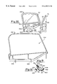
- FIG. 6 is a view of an interior portion of the motor vehicle of FIG. 4 taken in the direction of Arrow 6 of FIG. 4 illustrating attachment of the hard top to the body of the motor vehicle.
- FIG. 7 is an enlarged side view of a portion of the exemplary motor vehicle of FIGS. 1 and 2, partially cutaway to illustrate the support arrangement for the soft top.
- FIG. 8 is an enlarged partial view of the exemplary motor vehicle of FIGS. 1 and 2 similar to FIG. 7, illustrating the soft top rotated to an intermediate position.
- FIG. 9 is an enlarged view detailing the area identified in Circle 9 of FIG. 8 .
- FIG. 10 is an enlarged view taken in the direction of Arrow 10 of FIG. 7 showing a portion of the padding cut-away from the main hoop of the sport bar assembly to illustrate the mounting bracket for the bows of the soft top.
- FIG. 11 is a view of an interior portion of the exemplary motor vehicle of FIGS. 1 and 2 taken in the direction of Arrow 11 in FIG. 7 .
- FIG. 12A is a view similar to FIG. 11, illustrating the latching arrangement of the top system of the present invention interconnecting the soft top to the windshield frame.
- FIG. 12B is a side view of the latching arrangement of FIG. 12 A.
- FIG. 13 is a view similar to FIG. 11, illustrating the latching arrangement of the top system of the present invention interconnecting the hard top to the windshield.
- FIG. 14 is another enlarged perspective view of a portion of the exemplary motor vehicle of FIGS. 1 and 2, illustrating the step of attaching the deck fabric retainers into a horizontally oriented molded-in channel provided in a removable door frame assembly.
- FIG. 15 is another perspective view of a portion of the exemplary motor vehicle of FIGS. 1 and, illustrating the step of attaching the forward retainer in the quarter window into a vertically oriented molded-in channel provided in the removable door frame assembly.
- FIG. 16 is an enlarged perspective view of a portion of the exemplary motor vehicle of FIGS. 1 and 2, illustrating the step of attaching one of the side windows to the soft top.
- FIG. 17 is a further enlarged view of a portion of the exemplary motor vehicle of FIGS. 1 and 2.
- FIG. 18 is a rear view of the exemplary motor vehicle of FIGS. 1 and 2, illustrating the step of attaching the rear window to the soft top.
- FIG. 19 is a perspective view illustrating the step of attaching the rear corner retainers for the soft top.
- FIG. 20 is an enlarged view of a portion of the exemplary motor vehicle of FIGS. 1 and 2.
- FIG. 21 is a cross-sectional view taken along the line 21 — 21 of FIG. 20 .
- FIG. 22 is a cross-sectional vertically view taken through the removable door frame assembly of the present invention as it is operatively attached to the motor vehicle.
- FIG. 23 is an exploded view of a portion of the motor vehicle of FIGS. 1 and 2, illustrating the interconnection between the vehicle body and the removable door frame assembly.
- FIG. 24 is a top view of a portion of the motor vehicle of FIGS. 1 and 2 illustrating attachment of the removable door frame assembly to the sport bar assembly.
- FIG. 25 is a perspective view of one of the removable door frame assemblies of the present invention.
- FIG. 26 is another perspective view of the removable door frame assembly of FIG. 25 .
- FIG. 27 is a side view of the removable frame member of FIG. 20 illustrated in its operative position.
- FIG. 28 is a side view of the removable door frame assembly of FIG. 20 illustrated collapsed to a stored position.
- FIG. 29 is a cross-sectional view vertically taken through the removable window assembly of the present invention as it operatively attached to the motor vehicle.
- FIG. 30 is a rear side view of the removable window assembly of the present invention illustrated prior to attachment to the lower door assembly of the motor vehicle.
- FIG. 31 is a rear side view of the frame of the removable window assembly of the present invention.
- FIG. 32 is a portion of the cross-sectional view of FIG. 22 illustrating an alternative retainer element for interconnecting the soft top and the removable door frame assembly.
- the present invention relates to various aspects of an improved top system for a motor vehicle.
- the present invention more particularly relates to features of a top system which preferably includes both a hard top and a soft top.
- a top system which preferably includes both a hard top and a soft top.
- an apparatus for articulating the soft top between an operative position and a stored position (2) a removable door frame assembly; (3) a removable door window assembly; (4) a retainer member for attaching the soft top to the motor vehicle and shingling water away from the vehicle; (5) a multi-purpose retainer for the motor vehicle which facilitates selective attachment of the hard top and the soft top; (6) a latching arrangement for latching one of the tops to the motor vehicle; and (7) a top system in which the hard top may be operatively installed over the soft top.
- FIG. 1 shows the exemplary motor vehicle 10 with a soft top 12 installed to an operative position to protect passengers in the occupant compartment from wind, rain and other adverse weather conditions.
- FIG. 2 is an enlarged side view of the exemplary motor vehicle 10 shown with the soft top 12 folded to a stored position. In a manner which will be described below, the soft top 12 may be articulated between its operative position and its stored position.
- FIG. 3 shows the exemplary motor vehicle 10 with a hard top 14 mounted thereon.
- the exemplary motor vehicle 10 is shown to include a sport bar assembly 16 which upwardly extends from the vehicle body 18 .
- the sport bar assembly 16 is shown most clearly in FIG. 2 to include a main hoop 20 which is generally U-shaped.
- the main hoop 20 includes a pair a laterally spaced apart vertical members 22 interconnected by a transverse member 24 .
- the sport bar assembly 16 is shown to further include a pair of rear hoops 26 welded to the main hoop 20 and extending rearward therefrom.
- the sport bar assembly 16 includes a pair of side bars 28 bolted to the main hoop 20 and forwardly extending adjacent to a vehicle windshield assembly 30 .
- the side bars 28 are received in cylindrical recesses (not shown) provided in a frame 32 of the windshield assembly 30 .
- the sport bar assembly 16 is shown in the drawings partially covered with suitable padding 34 .
- the soft top 12 is constructed of fabric and illustrated to generally include a top section 36 , laterally spaced apart side sections 38 , and a rear section 40 .
- a quarter window 42 is attached to each of the laterally spaced apart side sections 38 with a zipper 44 .
- a zipper 46 attaches a rear window 48 to the rear section 40 .
- the motor vehicle 10 is shown to include an apparatus for articulating the soft top 12 between the operative position and the stored position. As will become apparent below, the apparatus further functions to support the soft top 12 in its operative position.
- the apparatus for articulating the soft top 12 has a plurality of support members including a forward support member 100 (or #1 bow), an intermediate support member 102 (or #2 bow), and a rearward support member 104 (or #3 bow).
- the #1 bow comprises a header portion 100 which is conventionally sewn within a forward edge 50 of the top section 36 of the soft top 12 (shown in FIG. 12 ).
- the #2 bow 102 transversely extends across the underside of the soft top 12 for supporting the fabric of the soft top 12 in a cross-car direction and the #3 bow 104 supports an upper rear corner 52 of the soft top 12 when the soft top 12 is in the operative position.
- the #1 bow 100 is interconnected to the motor vehicle 10 for rotation about a first transverse pivot axis through a pair of side bows 106 .
- the side bows 106 are each generally L-shaped, having a first end 107 operatively interconnected with the #1 bow 100 and a second end 108 pivotally attached to the main hoop 20 of the sport bar assembly 16 .
- the second ends 108 of the side bows 106 are each received in a knuckle 110 which is pivotally attached to a respective mounting plate 112 .
- the mounting plate 112 is fixedly attached to an associated vertical member 22 of the main hoop 20 of the sport bar assembly 16 with threaded fasteners 114 .
- the second ends 108 of the side bows 106 cooperate to define the first transverse pivot axis.
- the #3 bow 104 extends in a transverse direction and is captured within the upper rear edge 52 of the soft top 12 .
- the #3 bow 104 is preferably integrally formed with a pair of L-shaped members 116 which function to pivotally interconnect the #3 bow 104 to the motor vehicle 10 for rotation about a second transverse pivot axis.
- Both of the L-shaped members 116 of the #3 bow 104 include an end 118 which is received into a knuckle 120 pivotally attached to the mounting plate 112 .
- the ends 118 of the L-shaped members 116 cooperate to define the second transverse pivot axis.
- the first and second transverse pivot axes are spaced apart from each other both vertically and horizontally.
- the L-shaped members 116 attaching the #3 bow 104 to the sport bar assembly 20 both diverge in an outboard direction as they extend from the sport bar assembly 20 .
- This geometry provides a full shape for the soft top 12 in its operative position while allowing the plurality of support members 100 , 102 , and 104 to be positioned entirely within the body 18 of the vehicle 10 when the soft top 12 is stored. The significance of this feature will become more apparent below when concurrent mounting of the hard top 14 and the soft top 12 to the motor vehicle 10 is described.
- the soft top is installed in a specific manner in which the soft top is installed. Briefly, when the side sections 38 and the rear section 40 of the top 12 are attached to the motor vehicle 10 , the L-shaped members 116 are permitted to flex. Such flexing provides a spring load which serves as a counter-force to the fabric of the soft top 12 , thereby retaining the soft top 12 in a taut condition.
- the #2 bow 102 includes two downwardly extending ends 121 (shown most clearly in FIG. 9) which are supported on an associated one of the side bows 106 when the soft top 12 is in its installed position. To this end, each downwardly extending end 120 of the #2 bow 102 is attached to a support member 121 which defines a groove 124 for receiving one of the side bows 106 .
- the #2 bow 104 is preferably pivotally interconnected to each of the side bows 106 through a link rod 126 .
- the apparatus for articulating the soft top 12 of the present invention further includes a pair of tension straps 128 .
- Each of the tension straps 128 includes a first end 130 attached to one of the downwardly extending ends 121 of the #2 bow 102 and a second end 132 attached to one of the side bows 106 immediately adjacent the #3 bow 104 .
- the tension straps 128 cooperate to draw the soft top 12 taut in a longitudinal direction when the soft top 12 is in its operative position.
- the side bows 106 function to carry the #1 bow 100 and the #2 bow 102 through corresponding pivoting arcs from a cavity located between the rear seat 53 and the tailgate 54 to the top of the windshield frame 32 .
- the #3 bow 104 which when the soft top 12 in its operative position frames and supports the upper rear corner 52 of the soft top 12 , pivots about the second transverse pivot axis which is disposed immediately rearward and below the first transverse pivot axis.
- the #3 bow 104 pivots down to rest on the top of the rear wheel house panels 56 which are inboard of the body side panels 58 and forward of the tailgate 54 .
- the #2 bow 102 pivots on the side bows 102 to clear the rear hoops 26 of the sport bar assembly 16 .
- the #2 bow 102 comes to rest on the top of the L-shaped members 116 , and the side bow 106 and the #1 bow 100 come to rest on top of the #2 bow 102 .
- the fabric of the soft top 12 is attached to the #1, #2, and #3 bows 100 , 102 and 104 and is folded around and into a stowed bow assembly to form a minimal visible stack.
- a wrap or boot (not shown) may be used to gather the loose fabric and also may be used to contain the rear and quarter windows 48 and 42 .
- the top system of the present invention is shown to include a removable door frame assembly 200 .
- the removable door frame assembly 200 shown throughout the drawings is specifically configured for the driver's side of the motor vehicle 10 .
- the exemplary motor vehicle 10 includes a removable door frame assembly for the passenger's side which is a substantial mirror image thereof.
- the removable door frame assembly 200 continues the shut-face or opening aperture into which either a full door 59 or a removable window assembly 300 for a lower door assembly 60 sits.
- the removable door frame assembly 200 further functions to retain the top section 36 of the soft top 12 in a cross-car direction and the side section 38 of the soft top 12 in a longitudinally direction.
- the removable door frame assembly 200 is shown to include a first portion 202 which is adapted to releasably engage the motor vehicle 10 in a horizontal orientation and a second portion 204 adapted to releasably engage the motor vehicle 10 in a vertical orientation.
- the first and second portions 202 and 204 are pivotally interconnected with a pin 206 .
- Such pivotal interconnection permits the removable door frame assembly 200 to be folded (as specifically shown in FIG. 28 ), thereby facilitating storage within the motor vehicle 10 upon removal.
- the first portion 202 of the removable door frame assembly 200 is integrally formed to include a pair of mounting portions 208 .
- the mounting portions 208 are similarly constructed to include an upper flange 210 and a lower flange 212 which cooperate to partially define an arcuate recess 214 .
- the arcuate recess 214 is sized to receive one of the side bars 28 of the sport bar assembly 16 .
- the upper and lower flanges 210 and 212 are formed to include aligning apertures 216 and 218 , respectively, adapted to receive a threaded fastener 220 .
- the fastener 220 which has an oversized head 222 to facilitate manual installation, is passed through the aperture 216 in the upper flange 210 , through an aperture 224 in the side bar 28 , and engages a captured nut (not specifically shown) provided in the lower flange 212 .
- An upper side 226 of the first portion 202 is integrally formed to include a longitudinally extending recess 228 which accommodates an adjacent one of the side bows 106 when the soft top 12 is in the operative position.
- the first portion 202 is further integrally formed to include a downwardly extending lip 230 which partially defines the door shut-face. The downwardly extending lip 230 is adapted to abut a seal 62 carried by the full vehicle door 59 or the removable window assembly 300 .
- the second portion 204 of the removable door frame assembly 200 is integrally formed to include a lip or flange 232 (shown most clearly in FIG. 21) which forwardly extends and cooperates with the downwardly extending lip 230 of the first portion 202 to partially define the door shut-face.
- a lower end 234 of the second portion 204 is formed to include a cylindrical aperture 236 for receiving a locating pin 240 .
- the locating pin 240 is adapted to engage a B-pillar grommet assembly 242 carried by the vehicle body 18 .
- the lower end 234 of the second portion 204 is further integrally formed to include a downwardly extending flange 243 which cooperates with the body 18 of the vehicle 10 to prevent rotation of the second portion 204 relative to the motor vehicle 10 .
- the pin 240 and flange 243 cooperate to provide positive containment of the removable door frame assembly 200 in the longitudinally and cross-car directions, while being passive in a vertical direction.
- Vertical containment of the removable door frame assembly 200 is managed through the molded upper and lower flanges 210 and 212 of the first portion 202 which are attached to the side bar 28 .
- the first and second portions 202 and 204 of the removable door frame assembly 200 are formed to include molded-in-channels 244 and 246 , respectively, for retaining the soft top 12 in an operative position.
- the molded-in-channel 244 of the first portion 202 extends in a generally longitudinally direction and is adapted to removably receive a retainer element 400 fixedly attached to the top section 36 of the soft top 12 .
- the molded-in-channel 244 of the first portion 202 is defined by a generally U-shaped segment 248 of the first portion 202 which opens downwardly.
- the distal end of the segment 248 is angled slightly outward as it extends down to facilitate entry of the retainer element 400 .
- the retainer element 400 which is described in more detail in Section IV below, is retained under the tension of the top section 36 of the soft top 12 , thereby retaining and tensioning the soft top 12 in a cross-car direction.
- the molded-in-channel 246 (shown most clearly in FIG. 21) of the second portion 204 of the removable door frame assembly 200 is defined by a generally U-shaped segment 250 which is adapted to receive a portion of a U-shaped forward retainer element 62 fixedly attached to the side portion 38 of the soft top 12 .
- the retainer elements 62 and 400 are attached to their associated portions of the soft top 12 through stitching (not shown).
- the molded-in-channel 246 of the second portion 204 functions to longitudinally retain the side section 38 of the soft top 12 .
- the removable window assembly 300 of the present invention is shown to include a wire window frame 302 which defines a window opening 304 and a mounting arrangement for removably attaching the wire window frame 302 to the lower door assembly 60 .
- the mounting arrangement includes a plurality of wire pins 306 interconnected to the window frame 302 in a corresponding plurality of grommet assemblies 308 provided in an upper surface 310 of the lower door assembly 60 .
- the wire pins 306 are preferably L-shaped so as to position the outer surface of the door and its seals relative to the grommet assemblies 308 .
- the wire of the wire window frame 32 has a diameter sufficient to hold it against the seal flange (not specifically shown) carried by the windshield frame 32 .
- the grommet assemblies 308 define apertures 312 for receiving the pins 306 as a result of limited clearance between the pins 306 and their corresponding apertures 312 , the window frame 302 must be lifted in a substantially vertical direction in order to remove it from the lower door assembly 62 .
- the window frame 302 is configured to cooperate with the shut-face surface which is cooperatively provided by the lateral edge 64 of the windshield frame 32 and the removable door frame 200 .
- the lateral side 64 of the windshield frame 32 and the removable door frame assembly 200 laterally extend beyond the window frame 302 .
- the windshield frame 32 and the removable door frame assembly 200 cooperate as a passive interference device to prevent the window frame 302 from being removed when the lower door assembly 60 is closed while allowing the window frame 302 to be easily removed when the lower door assembly 60 is open.
- the retainer member 400 functions to retain the fabric of the soft top 12 in a cross-car direction (i.e., a transverse direction) and further functions to shingle the vehicle door 59 or 60 by forcing water (e.g., rain and condensation) to fall away from the top of the door 59 or 60 , thereby preventing water intrusion.
- a cross-car direction i.e., a transverse direction
- water e.g., rain and condensation
- the present invention preferably includes a pair of substantially identical retainer members 400 which interconnect a lateral edge 66 of the top section 36 of the soft top 12 with the molded-in channel 244 of the first portion 202 of the removable door frame assembly 200 .
- Each retainer member 400 is integrally formed of a rigid plastic material to include a first portion preferably in the form of a first flange 402 .
- the first flange 402 is adapted to be fixedly attached to the lateral edge 66 of the soft top 12 .
- the lateral edge 66 of the soft top 12 wraps around an edge 404 of the first flange 402 and is sewn to the first flange 402 .
- Each of the retainer members 400 is shown to further include a second portion 406 .
- the second portion 406 is illustrated to preferably comprise a second flange 406 adapted to be inserted into the molded-in channel or recess 244 of the removable door frame assembly 200 and cooperate with the channel 244 to oppose a bending moment introduced by tensioning of the soft top 12 in a lateral direction.
- the second flange 406 is shown to be preferably disposed at an obtuse angle relative to the first flange 402 .
- the channel 244 defined by the removable door frame assembly 200 is integrally molded into the first portion 202 of door frame assembly 200 and opens in a generally downward direction.
- the opposing sides 252 and 254 which define the molded-in channel 244 retain the retainer member 400 in an interference fit.
- the second flange 406 of the retainer member 404 is fully inserted into the channel 244 .
- the tension of the fabric top 12 in a lateral direction introduces a bending moment to the retaining element 400 which is opposed through contact of the opposing sides 252 and 254 with the second flange 406 , thus holding the soft top 12 cross-car between the doors 59 .
- the first flange 402 laterally extends beyond the removable door frame assembly 200 so that condensation and rain is laterally carried away from the door 59 .
- FIG. 32 an alternative construction of a retaining member 400 ′ is illustrated.
- the first flange 402 ′ is upwardly turned and interconnected to the second flange 406 ′ through an intermediate portion 412 .
- the first and second flanges 402 ′ and 406 ′ and the intermediate portion 412 cooperate to define a rain trough 414 for carrying water and condensation rearward.
- the fabric of the soft top 12 is attached (e.g., sewn) to both the intermediate portion 412 and the first flange 402 ′.
- the present invention is shown to include an apparatus 500 for selectively mounting the hard top 14 and the soft top 12 to the motor vehicle 10 .
- the apparatus for selectively mounting the hard top 14 and the soft top 12 further functions to cover a raw sheet metal edge of the body side panel 58 in an effective and cost efficient manner.
- the body side panel 58 (shown most clearly in FIG. 22) of the motor vehicle 10 upwardly extends and includes a generally horizontal upper portion 70 .
- the body side panel 58 also includes a downwardly extending distal flange 72 on the inboard side which terminates at a raw edge 74 .
- the apparatus comprises a retaining member 500 which is longitudinally elongated to extend the entire length of the body side panel 58 of the motor vehicle 10 .
- the retainer member 500 is shown to generally include an intermediate portion 502 , an outboard flange 504 and an inboard flange 506 .
- the intermediate portion 502 is adapted to be horizontally oriented and fixedly attached to the generally horizontal upper portion 70 of the body side panel 58 .
- the intermediate portion 502 is welded to the body side panel 58 .
- the retainer member 500 preferably extends around a rear corner 82 of the motor vehicle 10 and includes a substantially identical portion which is attached to a sheet metal panel adjacent the vehicle tailgate 54 .
- the upper surface of the intermediate portion 502 provides a flat surface for supporting the hard top 14 .
- the hard top 14 includes an inwardly extending flange 76 which rests on the intermediate portion 502 .
- Threaded fasteners 78 pass through apertures (not specifically shown) provided in the inwardly extending flange 76 and engage captured nuts 509 retained by the intermediate portion 502 .
- the outboard flange 504 downwardly extends from the intermediate portion 502 and terminates in an inner curled portion 510 .
- the inner curled portion 510 is spaced apart from the outer surface of the body side panel 58 of the motor vehicle 10 and defines a gap 512 for receiving one or more rigid retainers 80 (identified in FIG. 15) attached to the bottom edge of the side section 38 of the soft top 12 .
- the inboard flange 506 extends downwardly beyond the downwardly extending distal flange 72 of the body side panel 58 .
- the inboard flange 506 terminates at a curled inner edge 514 .
- the curled inner edge 514 functions to conceal the raw sheet metal edge 74 .
- the retainer member 500 is a one-piece, seamless and continuous part constructed from steel.
- the retainer member 500 is preferably welded to the body side panel 58 before the motor vehicle 10 is painted.
- the latching arrangement 600 as it relates to the soft top 12 is shown in FIG. 12 and as it relates to the hard top 14 in FIG. 13 .
- the latching arrangement 600 includes a latching mechanism 602 for the soft top 12 , a latching mechanism 604 for the hard top 14 , and a horizontally elongated slot 606 located in an upper portion of the windshield frame 32 .
- the slot 606 in the sheet metal of the windshield frame 32 is extruded and formed to present a rugged, durable attachment area.
- the latching mechanism 602 for the soft top 12 includes a pair of base plates 608 attached to the header 100 , a manually displaceable handle 610 and a hook member 612 .
- the handle 610 is pivotally attached to the base plates 608 , which are attached to spaced apart portions of the header 100 .
- the handle 610 is pivotable about an axis defined by a pin 614 between a latched position (shown in solid lines in FIG. 12A) and an unlatched position (shown in broken lines in FIG. 12 B).
- the hook member 612 of the latching mechanism 602 for the soft top 12 is shown in FIG. 12B pivotally attached to the handle through a pin 616 .
- the pivot axis for the hook member 612 defined by the pin 616 is offset from the pivot axis for the handle 610 .
- the pivot axis for the hook member 612 is slightly above the pivot axis for the handle 610 .
- an undercenter mechanical geometry essentially an overcenter mechanical geometry with a reverse orientation
- the handle 610 In latching the soft top 12 to the windshield frame 32 , the handle 610 is rotated downward to its latched position, and the hook member 612 is engaged with the horizontally elongated slot 606 . Such downward rotation of the handle member 610 draws the hook member 612 upward to engage the slot 606 .
- the handle 610 provides a lever arm for creating the necessary force to actuate the hook member 612 and further provides a mechanical advantage to draw the hook member 612 into the elongated slot 606 and compress a header seal (not shown) located on the top of the windshield frame 32 .
- the header seal and the fabric of the soft top 12 provide a resistance force for keeping the latching mechanism 602 in tension such that the undercenter orientation retains the latch mechanism 602 closed and secure.
- the latching mechanism 604 for the hard top 14 is illustrated in its latched position.
- the hook member 612 and handle 610 of the hard top latching mechanism 604 are identical in construction and function to corresponding elements of the soft top latching mechanism 602 .
- the base plates 618 of the hard top latching mechanism 604 similarly function to pivotally interconnect the handle with the top header 100 and are the only components not identical between the latching mechanisms 602 and 604 .
- the top system of the present invention allows the hard top 14 to be operatively installed over the folded soft top 12 .
- One purpose of this feature is to allow delivery of both tops 12 and 14 to the customer.
- Another purpose is to allow for an expanded range of uses of the vehicle 10 .
- the owner/user can have the hard top 14 on for greater comfort and less noise on long trips and on arrival, take the hard top 14 off and have the soft top 12 for local use with the benefit of open air driving.
- the soft top 12 is ready to be moved to its operative position or retained in the stored position for available protection from the element from adverse weather conditions.
- the ability of the top system to allow the hard top 14 to be operatively installed over the folded soft top 12 is made possible largely in part due to the several unique aspects of the present invention described above.
- the soft top 12 folds back and is contained within the boundaries of the body side 18 and the tailgate area while having a low stack height.
- the retainer members 500 welded onto the body side section 58 allow the tops 12 and 14 to function interchangeably.
- the captured nuts 509 carried in the retainer members 500 allow the hard top fasteners 78 to be easily accessible and installed even with the support bows 102 - 106 of the soft top 12 down in that area (as shown in FIG. 6 ).
- a lower rear portion (not specifically shown) of the hard top side section is configured with a clearance on each side to allow the soft top 12 to fit under the hard top 14 .
- the present invention is also directed to a method of installing the soft top 12 .
- Installation of the soft top 12 utilizing the features of the present invention provides an improved method of tensioning the fabric of the soft top 12 .
- the arrangement for articulating the soft top 12 especially the L-shaped members 116 connected to the #3 bow 104 , provides a spring load which serves as a counter-force to the fabric.
- the method of attaching the soft top 12 effectively employs a spring load in the bow assembly structure and the fabric of the soft top 12 without separate tensioning devices.
Abstract
Description
Claims (7)
Priority Applications (1)
| Application Number | Priority Date | Filing Date | Title |
|---|---|---|---|
| US08/955,667 US6295713B1 (en) | 1996-10-22 | 1997-10-22 | Method for attaching a soft top to a motor vehicle body |
Applications Claiming Priority (9)
| Application Number | Priority Date | Filing Date | Title |
|---|---|---|---|
| US2915496P | 1996-10-22 | 1996-10-22 | |
| US2899996P | 1996-10-23 | 1996-10-23 | |
| US2899596P | 1996-10-23 | 1996-10-23 | |
| US2899796P | 1996-10-23 | 1996-10-23 | |
| US2899696P | 1996-10-23 | 1996-10-23 | |
| US2899896P | 1996-10-23 | 1996-10-23 | |
| US2899496P | 1996-10-23 | 1996-10-23 | |
| US2973796P | 1996-11-23 | 1996-11-23 | |
| US08/955,667 US6295713B1 (en) | 1996-10-22 | 1997-10-22 | Method for attaching a soft top to a motor vehicle body |
Publications (1)
| Publication Number | Publication Date |
|---|---|
| US6295713B1 true US6295713B1 (en) | 2001-10-02 |
Family
ID=27578071
Family Applications (1)
| Application Number | Title | Priority Date | Filing Date |
|---|---|---|---|
| US08/955,667 Expired - Lifetime US6295713B1 (en) | 1996-10-22 | 1997-10-22 | Method for attaching a soft top to a motor vehicle body |
Country Status (1)
| Country | Link |
|---|---|
| US (1) | US6295713B1 (en) |
Cited By (33)
| Publication number | Priority date | Publication date | Assignee | Title |
|---|---|---|---|---|
| US6439643B2 (en) * | 2000-01-10 | 2002-08-27 | Dennis G. Barker | Mechanism for the retractable top of an open automobile |
| US20040056506A1 (en) * | 2002-09-19 | 2004-03-25 | Edscha Roof Systems Inc. | Retractable top system for vehicles with movable rear section |
| US20040189042A1 (en) * | 2003-03-27 | 2004-09-30 | Jarrard Brian M. | Soft cover for vehicles and process for making |
| US20040251707A1 (en) * | 2003-05-02 | 2004-12-16 | Garska Bradley R. | Convertible roof fabric attachment |
| US20050134096A1 (en) * | 2003-12-18 | 2005-06-23 | Cts Fahrzeug Dachsysteme Gmbh | Modular convertible top |
| US20050184563A1 (en) * | 2003-11-05 | 2005-08-25 | Zimmerly Craig M. | Method and apparatus for making a convertible top |
| US20050206197A1 (en) * | 2004-03-19 | 2005-09-22 | Troeger Rick H | Convertible soft top for a sport utility or similar vehicle |
| US20050258664A1 (en) * | 2002-09-09 | 2005-11-24 | Willard Michael T | Soft-top convertible roof system for an automotive vehicle |
| US20050285415A1 (en) * | 2004-06-25 | 2005-12-29 | Metts Carey G Iv | Soft top for vehicles |
| US20060017303A1 (en) * | 2004-07-20 | 2006-01-26 | Weege Michael E | Collapsible soft top cover and overhead rack sytem for a pickup truck |
| US20060119131A1 (en) * | 2004-12-03 | 2006-06-08 | Cts Fahrzeug Dachsysteme Gmbh | Manually removed cover and articulated cover supports for a vehicle |
| US20110101729A1 (en) * | 2009-10-29 | 2011-05-05 | Magna International Inc. | Lift assist system |
| US20120112491A1 (en) * | 2008-07-17 | 2012-05-10 | Sylkatis Michael E | Apparatus For Reducing Noise In a Soft Top Vehicle |
| US20120286540A1 (en) * | 2011-05-12 | 2012-11-15 | Moran Jeffrey A | Retractable Top for Off-Road Vehicles |
| US8608225B2 (en) | 2011-02-04 | 2013-12-17 | Ingenious Designs, Llc | Retractable top for an open vehicle |
| US8672389B2 (en) | 2011-02-04 | 2014-03-18 | Ingenious Designs, Llc | Retractable top for an open vehicle |
| US20140077521A1 (en) * | 2012-09-19 | 2014-03-20 | Gregory Donohoe | Vehicle Top |
| US20140339851A1 (en) * | 2013-05-15 | 2014-11-20 | Omix-Ada, Inc. | Manual Soft Top with Spring Assist Mechanism |
| US20150259011A1 (en) * | 2012-10-11 | 2015-09-17 | Polaris Industries Inc. | Side-by-side vehicle |
| US9216632B2 (en) | 2012-10-12 | 2015-12-22 | Bestop, Inc. | Sliding/folding soft top assembly for SUV |
| US9539887B2 (en) * | 2014-10-10 | 2017-01-10 | Magna Car Top Systems Of America, Inc. | Tensioning strap for a top stack seal |
| CN108839545A (en) * | 2018-07-31 | 2018-11-20 | 东莞龙迈汽车用品制造有限公司 | Software paulin |
| US10160300B2 (en) | 2016-11-30 | 2018-12-25 | Fca Us Llc | Vehicle soft top support bracket system |
| US10166848B2 (en) * | 2015-11-17 | 2019-01-01 | Bestop, Inc. | Locking lift assist for folding soft tops |
| US20190184800A1 (en) * | 2017-12-15 | 2019-06-20 | Ford Global Technologies, Llc | Dual fabric soft-top roof and method of using the same |
| US10913338B2 (en) | 2015-11-17 | 2021-02-09 | Bestop, Inc. | Lift assist lock-down for a soft top |
| US11273881B2 (en) | 2012-10-11 | 2022-03-15 | Polaris Industries Inc. | Side-by-side vehicle |
| USD955952S1 (en) | 2019-07-25 | 2022-06-28 | Polaris Industries Inc. | Door for a utility vehicle |
| USD962141S1 (en) | 2019-07-26 | 2022-08-30 | Polaris Industries Inc. | Vehicle door |
| US11447040B2 (en) | 2019-07-26 | 2022-09-20 | Polaris Industries Inc. | Side-by-side vehicle |
| US11511608B1 (en) * | 2022-03-17 | 2022-11-29 | Integrity Auto Group, Inc. | Vehicle strut and lifting device and system |
| US11607920B2 (en) | 2012-09-20 | 2023-03-21 | Polaris Industries Inc. | Vehicle |
| US11780326B2 (en) | 2012-09-20 | 2023-10-10 | Polaris Industries Inc. | Utility vehicle |
Citations (54)
| Publication number | Priority date | Publication date | Assignee | Title |
|---|---|---|---|---|
| DE129392C (en) | ||||
| US974072A (en) | 1909-07-10 | 1910-10-25 | Roy L Kenyon | Boat-canopy. |
| US1741318A (en) | 1928-12-28 | 1929-12-31 | Calvin Z Kroh | Motor-boat top |
| US1808298A (en) | 1928-12-04 | 1931-06-02 | Pont Eleuthere Paul Du | Automobile top |
| GB486283A (en) | 1936-11-03 | 1938-06-01 | Fiat Spa | Improvements relating to motor vehicle bodies |
| US2580337A (en) | 1949-01-10 | 1951-12-25 | Detroit Harvester Co | Folding top structure |
| US2682427A (en) | 1951-04-21 | 1954-06-29 | Willys Motors Inc | Removable collapsible vehicle door construction |
| US2697633A (en) | 1952-04-01 | 1954-12-21 | Clinton B D Brown | Collapsible vehicular top frame |
| US2817345A (en) | 1956-03-14 | 1957-12-24 | Sr Ralph S Woodruff | Boat canopy support |
| US2823684A (en) | 1956-01-20 | 1958-02-18 | Osvaldo F Sartori | Canopy for boats |
| US2864388A (en) | 1955-09-19 | 1958-12-16 | Kwikover Inc | Self-erecting tent |
| DE1152899B (en) | 1956-05-28 | 1963-08-14 | Claudius Dornier Jun Dipl Ing | Small vehicle, especially motor vehicle without doors |
| US3285259A (en) | 1963-11-29 | 1966-11-15 | Outboard Marine Corp | Folding soft top |
| US3307566A (en) | 1964-11-12 | 1967-03-07 | Outboard Marine Corp | Folding soft top |
| US3367349A (en) | 1966-03-14 | 1968-02-06 | Stearns Mfg Company | Boat canopy holding means |
| US3371672A (en) | 1966-05-31 | 1968-03-05 | Outboard Marine Corp | Convertible top |
| US3536354A (en) | 1966-04-07 | 1970-10-27 | Cyril J Ingram | Vehicle bodies |
| US3773379A (en) | 1972-08-31 | 1973-11-20 | W Loiseau | Folding cover for pickup truck |
| US3994524A (en) | 1973-05-30 | 1976-11-30 | Daimler-Benz Aktiengesellschaft | Control linkage for foldable top motor vehicles |
| US4066292A (en) | 1976-02-06 | 1978-01-03 | Carrozzeria Pininfarina S.P.A. | Automobile with sunshine roof |
| US4260188A (en) | 1978-06-10 | 1981-04-07 | Daimler-Benz Aktiengesellschaft | Hoop arrangement for foldable tops of automotive vehicles |
| US4310194A (en) | 1980-08-25 | 1982-01-12 | Biller Joseph A | Tent camper for pickup truck |
| DE3127525A1 (en) | 1981-07-11 | 1983-01-27 | Dr.Ing.H.C. F. Porsche Ag, 7000 Stuttgart | Motor vehicle having a body which exhibits a roll-over bar and with a folding top |
| US4402544A (en) | 1982-01-07 | 1983-09-06 | Artim Rufus R | Folding canopy for truck and trailer loads |
| US4440436A (en) | 1982-05-06 | 1984-04-03 | Giddens Marian S | Convertible top for motorcycles and snowmobiles |
| EP0146884A2 (en) | 1983-12-21 | 1985-07-03 | Lamberto Masi | Adjustable air shield for the windows of motor vehicles |
| CH652977A5 (en) | 1980-02-18 | 1985-12-13 | Steyr Daimler Puch Ag | Hinged folding top on a motor vehicle, in particular an off-road vehicle |
| US4593641A (en) | 1984-08-07 | 1986-06-10 | Adams Charles C | Universal frame for boat mounted game blind |
| US4639034A (en) | 1985-05-06 | 1987-01-27 | American Insulation & Engineering Co., Inc. | Soft top for pick-up trucks |
| US4729593A (en) | 1986-02-19 | 1988-03-08 | Mazda Motor Corporation | Convertible vehicle body |
| JPS63192631A (en) | 1987-02-03 | 1988-08-10 | Daihatsu Motor Co Ltd | Hood supporting mechanism for hood car |
| US4789196A (en) | 1986-09-02 | 1988-12-06 | Transmatic, Incorporated | Convertible top for pick-up trucks |
| JPS6464623A (en) | 1987-09-03 | 1989-03-10 | Topcon Corp | Gas stream spray apparatus of non-contact type ocular tonometer |
| US4828317A (en) | 1987-02-10 | 1989-05-09 | Muscat Peter P | Convertible top frame with quarter windows |
| US4850634A (en) | 1986-09-22 | 1989-07-25 | Gebr. Haslbeck Gmbh | Folding top for cross-country vehicles |
| JPH024129A (en) | 1988-06-22 | 1990-01-09 | Hitachi Ltd | Supporting structure for gas turbine combustion device |
| US4898420A (en) | 1988-05-23 | 1990-02-06 | Suzuki Motor Company, Limited | Vehicular openable roof hood |
| US4915440A (en) | 1989-03-08 | 1990-04-10 | Daniel Avis U | Truck bed cover |
| US4927202A (en) | 1988-09-12 | 1990-05-22 | C & C Incorporated | Convertible top vinyl push-out |
| US4964669A (en) | 1989-11-13 | 1990-10-23 | Geier William F | Foldable top for truck bed |
| US5004291A (en) | 1987-07-24 | 1991-04-02 | Daimler-Berg Ag | Top framework of a folding top for vehicles |
| US5005896A (en) | 1990-01-22 | 1991-04-09 | Li Cheng Chia | Retractable truck canopy frame |
| US5042868A (en) | 1989-05-03 | 1991-08-27 | Ed. Scharwachter Gmbh & Co. Kg | Driving mechanism for a motor-driven convertible roof |
| US5058943A (en) | 1990-02-09 | 1991-10-22 | Clyde McKee | Foldable canopy assembly for motorized vehicles |
| US5066063A (en) | 1990-09-17 | 1991-11-19 | Mullally Regis K | Removable cover for a truck cargo box |
| US5072987A (en) | 1990-06-18 | 1991-12-17 | Allen Marshall T | Retractable cycle roof |
| DE4114823A1 (en) | 1991-05-07 | 1992-11-12 | Niemann Hubert | Collapsible roof for cross country vehicle - consists of separate front and rear sections, each with their own covering |
| US5238288A (en) | 1992-06-15 | 1993-08-24 | Chandler M Robert | Pick-up truck bed collapsible cover |
| US5299850A (en) | 1991-08-28 | 1994-04-05 | Suzuki Motor Corporation | Automobile with canvas |
| US5303667A (en) | 1991-07-22 | 1994-04-19 | Aldon Industries, Inc. | Boat camper system and method |
| US5385377A (en) | 1992-10-08 | 1995-01-31 | Canvasback Convertible Tops Inc. | Pickup truck bed covers and attachment system therefore |
| US5531497A (en) | 1993-05-10 | 1996-07-02 | Cheng; John C. | Two-position collapsible canopy assembly that attaches to a pickup truck |
| US5556156A (en) | 1993-10-01 | 1996-09-17 | Kirk; Alan J. E. | Flexible collapsible utility truck bed cover |
| US5673959A (en) | 1994-11-28 | 1997-10-07 | Padlo; Craig W. | Foldable convertible flexible-roof support |
-
1997
- 1997-10-22 US US08/955,667 patent/US6295713B1/en not_active Expired - Lifetime
Patent Citations (55)
| Publication number | Priority date | Publication date | Assignee | Title |
|---|---|---|---|---|
| DE129392C (en) | ||||
| US974072A (en) | 1909-07-10 | 1910-10-25 | Roy L Kenyon | Boat-canopy. |
| US1808298A (en) | 1928-12-04 | 1931-06-02 | Pont Eleuthere Paul Du | Automobile top |
| US1741318A (en) | 1928-12-28 | 1929-12-31 | Calvin Z Kroh | Motor-boat top |
| GB486283A (en) | 1936-11-03 | 1938-06-01 | Fiat Spa | Improvements relating to motor vehicle bodies |
| US2580337A (en) | 1949-01-10 | 1951-12-25 | Detroit Harvester Co | Folding top structure |
| US2682427A (en) | 1951-04-21 | 1954-06-29 | Willys Motors Inc | Removable collapsible vehicle door construction |
| US2697633A (en) | 1952-04-01 | 1954-12-21 | Clinton B D Brown | Collapsible vehicular top frame |
| US2864388A (en) | 1955-09-19 | 1958-12-16 | Kwikover Inc | Self-erecting tent |
| US2823684A (en) | 1956-01-20 | 1958-02-18 | Osvaldo F Sartori | Canopy for boats |
| US2817345A (en) | 1956-03-14 | 1957-12-24 | Sr Ralph S Woodruff | Boat canopy support |
| DE1152899B (en) | 1956-05-28 | 1963-08-14 | Claudius Dornier Jun Dipl Ing | Small vehicle, especially motor vehicle without doors |
| US3285259A (en) | 1963-11-29 | 1966-11-15 | Outboard Marine Corp | Folding soft top |
| US3307566A (en) | 1964-11-12 | 1967-03-07 | Outboard Marine Corp | Folding soft top |
| US3367349A (en) | 1966-03-14 | 1968-02-06 | Stearns Mfg Company | Boat canopy holding means |
| US3536354A (en) | 1966-04-07 | 1970-10-27 | Cyril J Ingram | Vehicle bodies |
| US3371672A (en) | 1966-05-31 | 1968-03-05 | Outboard Marine Corp | Convertible top |
| US3773379A (en) | 1972-08-31 | 1973-11-20 | W Loiseau | Folding cover for pickup truck |
| US3994524A (en) | 1973-05-30 | 1976-11-30 | Daimler-Benz Aktiengesellschaft | Control linkage for foldable top motor vehicles |
| US4066292A (en) | 1976-02-06 | 1978-01-03 | Carrozzeria Pininfarina S.P.A. | Automobile with sunshine roof |
| US4260188A (en) | 1978-06-10 | 1981-04-07 | Daimler-Benz Aktiengesellschaft | Hoop arrangement for foldable tops of automotive vehicles |
| CH652977A5 (en) | 1980-02-18 | 1985-12-13 | Steyr Daimler Puch Ag | Hinged folding top on a motor vehicle, in particular an off-road vehicle |
| US4310194A (en) | 1980-08-25 | 1982-01-12 | Biller Joseph A | Tent camper for pickup truck |
| DE3127525A1 (en) | 1981-07-11 | 1983-01-27 | Dr.Ing.H.C. F. Porsche Ag, 7000 Stuttgart | Motor vehicle having a body which exhibits a roll-over bar and with a folding top |
| US4402544A (en) | 1982-01-07 | 1983-09-06 | Artim Rufus R | Folding canopy for truck and trailer loads |
| US4440436A (en) | 1982-05-06 | 1984-04-03 | Giddens Marian S | Convertible top for motorcycles and snowmobiles |
| EP0146884A2 (en) | 1983-12-21 | 1985-07-03 | Lamberto Masi | Adjustable air shield for the windows of motor vehicles |
| US4593641A (en) | 1984-08-07 | 1986-06-10 | Adams Charles C | Universal frame for boat mounted game blind |
| US4639034A (en) | 1985-05-06 | 1987-01-27 | American Insulation & Engineering Co., Inc. | Soft top for pick-up trucks |
| US4729593A (en) | 1986-02-19 | 1988-03-08 | Mazda Motor Corporation | Convertible vehicle body |
| US4789196A (en) | 1986-09-02 | 1988-12-06 | Transmatic, Incorporated | Convertible top for pick-up trucks |
| US4850634A (en) | 1986-09-22 | 1989-07-25 | Gebr. Haslbeck Gmbh | Folding top for cross-country vehicles |
| JPS63192631A (en) | 1987-02-03 | 1988-08-10 | Daihatsu Motor Co Ltd | Hood supporting mechanism for hood car |
| US4828317A (en) | 1987-02-10 | 1989-05-09 | Muscat Peter P | Convertible top frame with quarter windows |
| US5004291A (en) | 1987-07-24 | 1991-04-02 | Daimler-Berg Ag | Top framework of a folding top for vehicles |
| JPS6464623A (en) | 1987-09-03 | 1989-03-10 | Topcon Corp | Gas stream spray apparatus of non-contact type ocular tonometer |
| US4898420A (en) | 1988-05-23 | 1990-02-06 | Suzuki Motor Company, Limited | Vehicular openable roof hood |
| JPH024129A (en) | 1988-06-22 | 1990-01-09 | Hitachi Ltd | Supporting structure for gas turbine combustion device |
| US4927202A (en) | 1988-09-12 | 1990-05-22 | C & C Incorporated | Convertible top vinyl push-out |
| US4915440A (en) | 1989-03-08 | 1990-04-10 | Daniel Avis U | Truck bed cover |
| US5042868A (en) | 1989-05-03 | 1991-08-27 | Ed. Scharwachter Gmbh & Co. Kg | Driving mechanism for a motor-driven convertible roof |
| US4964669A (en) | 1989-11-13 | 1990-10-23 | Geier William F | Foldable top for truck bed |
| US5005896A (en) | 1990-01-22 | 1991-04-09 | Li Cheng Chia | Retractable truck canopy frame |
| US5058943A (en) | 1990-02-09 | 1991-10-22 | Clyde McKee | Foldable canopy assembly for motorized vehicles |
| US5072987A (en) | 1990-06-18 | 1991-12-17 | Allen Marshall T | Retractable cycle roof |
| US5066063A (en) | 1990-09-17 | 1991-11-19 | Mullally Regis K | Removable cover for a truck cargo box |
| DE4114823A1 (en) | 1991-05-07 | 1992-11-12 | Niemann Hubert | Collapsible roof for cross country vehicle - consists of separate front and rear sections, each with their own covering |
| US5303667A (en) | 1991-07-22 | 1994-04-19 | Aldon Industries, Inc. | Boat camper system and method |
| US5299850A (en) | 1991-08-28 | 1994-04-05 | Suzuki Motor Corporation | Automobile with canvas |
| US5238288A (en) | 1992-06-15 | 1993-08-24 | Chandler M Robert | Pick-up truck bed collapsible cover |
| US5385377A (en) | 1992-10-08 | 1995-01-31 | Canvasback Convertible Tops Inc. | Pickup truck bed covers and attachment system therefore |
| US5531497A (en) | 1993-05-10 | 1996-07-02 | Cheng; John C. | Two-position collapsible canopy assembly that attaches to a pickup truck |
| US5556156A (en) | 1993-10-01 | 1996-09-17 | Kirk; Alan J. E. | Flexible collapsible utility truck bed cover |
| US5673959A (en) | 1994-11-28 | 1997-10-07 | Padlo; Craig W. | Foldable convertible flexible-roof support |
| US5673959B1 (en) | 1994-11-28 | 2000-05-02 | Craig W Padlo | Foldable convertible flexible-roof support |
Non-Patent Citations (1)
| Title |
|---|
| Robert C. Ackerson, Standard Catalog of 4x4's 1945-1993, pp. 385-415. |
Cited By (60)
| Publication number | Priority date | Publication date | Assignee | Title |
|---|---|---|---|---|
| US6439643B2 (en) * | 2000-01-10 | 2002-08-27 | Dennis G. Barker | Mechanism for the retractable top of an open automobile |
| US7118160B2 (en) | 2002-09-09 | 2006-10-10 | Asc Incorporated | Soft-top convertible roof system for an automotive vehicle |
| US20050258664A1 (en) * | 2002-09-09 | 2005-11-24 | Willard Michael T | Soft-top convertible roof system for an automotive vehicle |
| US20040056506A1 (en) * | 2002-09-19 | 2004-03-25 | Edscha Roof Systems Inc. | Retractable top system for vehicles with movable rear section |
| DE10343128B4 (en) * | 2002-09-19 | 2009-06-10 | Edscha Cabrio-Dachsysteme Gmbh | Removable roof for a motor vehicle |
| US6971705B2 (en) | 2002-09-19 | 2005-12-06 | Edscha Roof Systems, Inc. | Retractable top system for vehicles with movable rear section |
| US20040189042A1 (en) * | 2003-03-27 | 2004-09-30 | Jarrard Brian M. | Soft cover for vehicles and process for making |
| US6871898B2 (en) | 2003-03-27 | 2005-03-29 | Omnova Solutions Inc. | Soft cover for vehicles and process for making |
| US20040251707A1 (en) * | 2003-05-02 | 2004-12-16 | Garska Bradley R. | Convertible roof fabric attachment |
| US7144063B2 (en) | 2003-05-02 | 2006-12-05 | Asc Incorporated | Convertible roof fabric attachment |
| US20050184563A1 (en) * | 2003-11-05 | 2005-08-25 | Zimmerly Craig M. | Method and apparatus for making a convertible top |
| US7354094B2 (en) | 2003-11-05 | 2008-04-08 | Magna Cartop Systems Of America, Inc. | Method and apparatus for making a convertible top |
| US20070257521A1 (en) * | 2003-12-18 | 2007-11-08 | Magna Car Top Systems Gmbh | Modular convertible top |
| US7240960B2 (en) | 2003-12-18 | 2007-07-10 | Magna Car Top Systems Gmbh | Modular convertible top |
| US20050134096A1 (en) * | 2003-12-18 | 2005-06-23 | Cts Fahrzeug Dachsysteme Gmbh | Modular convertible top |
| US7523977B2 (en) | 2003-12-18 | 2009-04-28 | Magna Car Top Systems Gmbh | Modular convertible top |
| US20050206197A1 (en) * | 2004-03-19 | 2005-09-22 | Troeger Rick H | Convertible soft top for a sport utility or similar vehicle |
| US7029052B2 (en) * | 2004-03-19 | 2006-04-18 | Bestop, Inc. | Convertible soft top for a sport utility or similar vehicle |
| US7213866B2 (en) | 2004-06-25 | 2007-05-08 | Metts Iv Carey Gregory | Soft top for vehicles |
| US20050285415A1 (en) * | 2004-06-25 | 2005-12-29 | Metts Carey G Iv | Soft top for vehicles |
| US20060017303A1 (en) * | 2004-07-20 | 2006-01-26 | Weege Michael E | Collapsible soft top cover and overhead rack sytem for a pickup truck |
| US20060119131A1 (en) * | 2004-12-03 | 2006-06-08 | Cts Fahrzeug Dachsysteme Gmbh | Manually removed cover and articulated cover supports for a vehicle |
| US7469954B2 (en) | 2004-12-03 | 2008-12-30 | Magna Car Top Systems Gmbh | Manually removed cover and articulated cover supports for a vehicle |
| US20120112491A1 (en) * | 2008-07-17 | 2012-05-10 | Sylkatis Michael E | Apparatus For Reducing Noise In a Soft Top Vehicle |
| US8240743B2 (en) * | 2008-07-17 | 2012-08-14 | Michael Sylkatis | Apparatus for reducing noise in a soft top vehicle |
| US20110101729A1 (en) * | 2009-10-29 | 2011-05-05 | Magna International Inc. | Lift assist system |
| US7992919B2 (en) * | 2009-10-29 | 2011-08-09 | Magna International Inc. | Lift assist system |
| US8672389B2 (en) | 2011-02-04 | 2014-03-18 | Ingenious Designs, Llc | Retractable top for an open vehicle |
| US8608225B2 (en) | 2011-02-04 | 2013-12-17 | Ingenious Designs, Llc | Retractable top for an open vehicle |
| US9415669B2 (en) | 2011-02-04 | 2016-08-16 | Ingenious Designs, Llc | Retractable top for an open vehicle |
| US8474899B2 (en) * | 2011-05-12 | 2013-07-02 | Omix-Ada, Inc. | Retractable top for off-road vehicles |
| US20120286540A1 (en) * | 2011-05-12 | 2012-11-15 | Moran Jeffrey A | Retractable Top for Off-Road Vehicles |
| US20140077521A1 (en) * | 2012-09-19 | 2014-03-20 | Gregory Donohoe | Vehicle Top |
| US8944486B2 (en) * | 2012-09-19 | 2015-02-03 | Gregory Donohoe | Vehicle top |
| US11926190B2 (en) | 2012-09-20 | 2024-03-12 | Polaris Industries Inc. | Vehicle |
| US11951794B2 (en) | 2012-09-20 | 2024-04-09 | Polaris Industries Inc. | Vehicle |
| US11787251B2 (en) | 2012-09-20 | 2023-10-17 | Polaris Industries Inc. | Vehicle |
| US11780326B2 (en) | 2012-09-20 | 2023-10-10 | Polaris Industries Inc. | Utility vehicle |
| US11607920B2 (en) | 2012-09-20 | 2023-03-21 | Polaris Industries Inc. | Vehicle |
| US20150259011A1 (en) * | 2012-10-11 | 2015-09-17 | Polaris Industries Inc. | Side-by-side vehicle |
| US11273881B2 (en) | 2012-10-11 | 2022-03-15 | Polaris Industries Inc. | Side-by-side vehicle |
| US9776481B2 (en) * | 2012-10-11 | 2017-10-03 | Polaris Industries Inc. | Side-by-side vehicle |
| US9216632B2 (en) | 2012-10-12 | 2015-12-22 | Bestop, Inc. | Sliding/folding soft top assembly for SUV |
| US10173504B2 (en) | 2012-10-12 | 2019-01-08 | Bestop, Inc. | Sliding / folding soft top assembly for SUV |
| US20140339851A1 (en) * | 2013-05-15 | 2014-11-20 | Omix-Ada, Inc. | Manual Soft Top with Spring Assist Mechanism |
| US9045026B2 (en) * | 2013-05-15 | 2015-06-02 | Omix-Ada, Inc. | Manual soft top with spring assist mechanism |
| US9539887B2 (en) * | 2014-10-10 | 2017-01-10 | Magna Car Top Systems Of America, Inc. | Tensioning strap for a top stack seal |
| US10913338B2 (en) | 2015-11-17 | 2021-02-09 | Bestop, Inc. | Lift assist lock-down for a soft top |
| US10166848B2 (en) * | 2015-11-17 | 2019-01-01 | Bestop, Inc. | Locking lift assist for folding soft tops |
| US10160300B2 (en) | 2016-11-30 | 2018-12-25 | Fca Us Llc | Vehicle soft top support bracket system |
| US20190184800A1 (en) * | 2017-12-15 | 2019-06-20 | Ford Global Technologies, Llc | Dual fabric soft-top roof and method of using the same |
| US10787067B2 (en) * | 2017-12-15 | 2020-09-29 | Ford Global Technologies, Llc | Dual fabric soft-top roof and method of using the same |
| CN108839545A (en) * | 2018-07-31 | 2018-11-20 | 东莞龙迈汽车用品制造有限公司 | Software paulin |
| USD955952S1 (en) | 2019-07-25 | 2022-06-28 | Polaris Industries Inc. | Door for a utility vehicle |
| US11447040B2 (en) | 2019-07-26 | 2022-09-20 | Polaris Industries Inc. | Side-by-side vehicle |
| USD962141S1 (en) | 2019-07-26 | 2022-08-30 | Polaris Industries Inc. | Vehicle door |
| CN115871425A (en) * | 2022-03-17 | 2023-03-31 | 诚信汽车集团有限公司 | Vehicle pillar and lifting device and system |
| US11685240B1 (en) | 2022-03-17 | 2023-06-27 | Integrity Auto Group, Inc. | Vehicle strut and lifting device and system |
| US11511608B1 (en) * | 2022-03-17 | 2022-11-29 | Integrity Auto Group, Inc. | Vehicle strut and lifting device and system |
| CN115871425B (en) * | 2022-03-17 | 2023-10-20 | 诚信汽车集团有限公司 | Post lifting system for rear cargo soft roof of vehicle |
Similar Documents
| Publication | Publication Date | Title |
|---|---|---|
| US6295713B1 (en) | Method for attaching a soft top to a motor vehicle body | |
| US6036256A (en) | Window assembly for a motor vehicle | |
| US5992917A (en) | Top system for a motor vehicle | |
| US5947546A (en) | Apparatus for attaching a soft top to a motor vehicle | |
| US5829821A (en) | Folding top of a vehicle | |
| US6073989A (en) | Removable door frame assembly for a motor vehicle | |
| US11331989B2 (en) | Tonneau cover access panel | |
| US20210362573A1 (en) | Soft front cockpit cover | |
| US7523977B2 (en) | Modular convertible top | |
| US5673959A (en) | Foldable convertible flexible-roof support | |
| US5810422A (en) | Convertible top | |
| US5353826A (en) | Tent topper | |
| US6439643B2 (en) | Mechanism for the retractable top of an open automobile | |
| US7448666B2 (en) | Golf cart cover with integrated storage boot | |
| US5058943A (en) | Foldable canopy assembly for motorized vehicles | |
| US11084359B2 (en) | Sliding / folding slanted back soft top assembly for SUV | |
| US5775767A (en) | Convertible top for a vehicle having a rear egress | |
| US5979969A (en) | Apparatus for selectively mounting a hard top and a soft top to a motor vehicle | |
| US4566728A (en) | Hatchback vehicle body including hatch having opening with soft top convertible closure | |
| US6409248B1 (en) | Dual pivoting bow assembly for use with a removable soft top portion of a jeep-top cover | |
| US20030080581A1 (en) | Convertible having a top storable underneath a plane of a top cover | |
| US11712952B2 (en) | Pivotal soft top cover with secondary bow linked | |
| USRE38546E1 (en) | Convertible top | |
| US6688669B2 (en) | Motor vehicle having a folding roof which can be opened | |
| US11685241B2 (en) | Soft front cockpit cover with linkage |
Legal Events
| Date | Code | Title | Description |
|---|---|---|---|
| AS | Assignment |
Owner name: BESTOP, INC., COLORADO Free format text: ASSIGNMENT OF ASSIGNORS INTEREST;ASSIGNORS:HILLIARD, MICHAEL E.;DELELLIS, LOUIS D.;GRABOWSKI, WILLIAM A.;AND OTHERS;REEL/FRAME:010032/0158;SIGNING DATES FROM 19980312 TO 19990615 Owner name: CHRYSLER CORPORATION, MICHIGAN Free format text: ASSIGNMENT OF ASSIGNORS INTEREST;ASSIGNORS:HILLIARD, MICHAEL E.;DELELLIS, LOUIS D.;GRABOWSKI, WILLIAM A.;AND OTHERS;REEL/FRAME:010032/0158;SIGNING DATES FROM 19980312 TO 19990615 |
|
| STCF | Information on status: patent grant |
Free format text: PATENTED CASE |
|
| FPAY | Fee payment |
Year of fee payment: 4 |
|
| AS | Assignment |
Owner name: DAIMLERCHRYSLER CORPORATION, MICHIGAN Free format text: CHANGE OF NAME;ASSIGNOR:CHRYSLER CORPORATION;REEL/FRAME:016914/0025 Effective date: 19981116 |
|
| AS | Assignment |
Owner name: WILMINGTON TRUST COMPANY, DELAWARE Free format text: GRANT OF SECURITY INTEREST IN PATENT RIGHTS - FIRST PRIORITY;ASSIGNOR:CHRYSLER LLC;REEL/FRAME:019773/0001 Effective date: 20070803 Owner name: WILMINGTON TRUST COMPANY,DELAWARE Free format text: GRANT OF SECURITY INTEREST IN PATENT RIGHTS - FIRST PRIORITY;ASSIGNOR:CHRYSLER LLC;REEL/FRAME:019773/0001 Effective date: 20070803 |
|
| AS | Assignment |
Owner name: WILMINGTON TRUST COMPANY, DELAWARE Free format text: GRANT OF SECURITY INTEREST IN PATENT RIGHTS - SECOND PRIORITY;ASSIGNOR:CHRYSLER LLC;REEL/FRAME:019767/0810 Effective date: 20070803 Owner name: WILMINGTON TRUST COMPANY,DELAWARE Free format text: GRANT OF SECURITY INTEREST IN PATENT RIGHTS - SECOND PRIORITY;ASSIGNOR:CHRYSLER LLC;REEL/FRAME:019767/0810 Effective date: 20070803 |
|
| AS | Assignment |
Owner name: US DEPARTMENT OF THE TREASURY, DISTRICT OF COLUMBI Free format text: GRANT OF SECURITY INTEREST IN PATENT RIGHTS - THIR;ASSIGNOR:CHRYSLER LLC;REEL/FRAME:022259/0188 Effective date: 20090102 Owner name: US DEPARTMENT OF THE TREASURY,DISTRICT OF COLUMBIA Free format text: GRANT OF SECURITY INTEREST IN PATENT RIGHTS - THIR;ASSIGNOR:CHRYSLER LLC;REEL/FRAME:022259/0188 Effective date: 20090102 |
|
| FPAY | Fee payment |
Year of fee payment: 8 |
|
| AS | Assignment |
Owner name: CHRYSLER LLC, MICHIGAN Free format text: RELEASE BY SECURED PARTY;ASSIGNOR:US DEPARTMENT OF THE TREASURY;REEL/FRAME:022910/0273 Effective date: 20090608 |
|
| AS | Assignment |
Owner name: CHRYSLER LLC, MICHIGAN Free format text: RELEASE OF SECURITY INTEREST IN PATENT RIGHTS - FIRST PRIORITY;ASSIGNOR:WILMINGTON TRUST COMPANY;REEL/FRAME:022910/0498 Effective date: 20090604 Owner name: CHRYSLER LLC, MICHIGAN Free format text: RELEASE OF SECURITY INTEREST IN PATENT RIGHTS - SECOND PRIORITY;ASSIGNOR:WILMINGTON TRUST COMPANY;REEL/FRAME:022910/0740 Effective date: 20090604 Owner name: NEW CARCO ACQUISITION LLC, MICHIGAN Free format text: ASSIGNMENT OF ASSIGNORS INTEREST;ASSIGNOR:CHRYSLER LLC;REEL/FRAME:022915/0001 Effective date: 20090610 Owner name: THE UNITED STATES DEPARTMENT OF THE TREASURY, DIST Free format text: SECURITY AGREEMENT;ASSIGNOR:NEW CARCO ACQUISITION LLC;REEL/FRAME:022915/0489 Effective date: 20090610 Owner name: CHRYSLER LLC,MICHIGAN Free format text: RELEASE OF SECURITY INTEREST IN PATENT RIGHTS - FIRST PRIORITY;ASSIGNOR:WILMINGTON TRUST COMPANY;REEL/FRAME:022910/0498 Effective date: 20090604 Owner name: CHRYSLER LLC,MICHIGAN Free format text: RELEASE OF SECURITY INTEREST IN PATENT RIGHTS - SECOND PRIORITY;ASSIGNOR:WILMINGTON TRUST COMPANY;REEL/FRAME:022910/0740 Effective date: 20090604 Owner name: NEW CARCO ACQUISITION LLC,MICHIGAN Free format text: ASSIGNMENT OF ASSIGNORS INTEREST;ASSIGNOR:CHRYSLER LLC;REEL/FRAME:022915/0001 Effective date: 20090610 Owner name: THE UNITED STATES DEPARTMENT OF THE TREASURY,DISTR Free format text: SECURITY AGREEMENT;ASSIGNOR:NEW CARCO ACQUISITION LLC;REEL/FRAME:022915/0489 Effective date: 20090610 |
|
| AS | Assignment |
Owner name: CHRYSLER GROUP LLC, MICHIGAN Free format text: CHANGE OF NAME;ASSIGNOR:NEW CARCO ACQUISITION LLC;REEL/FRAME:022919/0126 Effective date: 20090610 Owner name: CHRYSLER GROUP LLC,MICHIGAN Free format text: CHANGE OF NAME;ASSIGNOR:NEW CARCO ACQUISITION LLC;REEL/FRAME:022919/0126 Effective date: 20090610 |
|
| AS | Assignment |
Owner name: CHRYSLER GROUP GLOBAL ELECTRIC MOTORCARS LLC, NORT Free format text: RELEASE BY SECURED PARTY;ASSIGNOR:THE UNITED STATES DEPARTMENT OF THE TREASURY;REEL/FRAME:026343/0298 Effective date: 20110524 Owner name: CHRYSLER GROUP LLC, MICHIGAN Free format text: RELEASE BY SECURED PARTY;ASSIGNOR:THE UNITED STATES DEPARTMENT OF THE TREASURY;REEL/FRAME:026343/0298 Effective date: 20110524 |
|
| AS | Assignment |
Owner name: CITIBANK, N.A., NEW YORK Free format text: SECURITY AGREEMENT;ASSIGNOR:CHRYSLER GROUP LLC;REEL/FRAME:026404/0123 Effective date: 20110524 |
|
| AS | Assignment |
Owner name: CITIBANK, N.A., NEW YORK Free format text: SECURITY AGREEMENT;ASSIGNOR:CHRYSLER GROUP LLC;REEL/FRAME:026435/0652 Effective date: 20110524 |
|
| FPAY | Fee payment |
Year of fee payment: 12 |
|
| AS | Assignment |
Owner name: JPMORGAN CHASE BANK, N.A., ILLINOIS Free format text: SECURITY AGREEMENT;ASSIGNOR:CHRYSLER GROUP LLC;REEL/FRAME:032384/0640 Effective date: 20140207 |
|
| AS | Assignment |
Owner name: FCA US LLC, MICHIGAN Free format text: CHANGE OF NAME;ASSIGNOR:CHRYSLER GROUP LLC;REEL/FRAME:035553/0356 Effective date: 20141203 |
|
| AS | Assignment |
Owner name: GENERAL ELECTRIC CAPITAL CORPORATION, ILLINOIS Free format text: SECURITY INTEREST;ASSIGNOR:BT OPERATING COMPANY, INC.;REEL/FRAME:036216/0914 Effective date: 20150730 Owner name: BT OPERATING COMPANY, INC., COLORADO Free format text: ASSIGNMENT OF ASSIGNORS INTEREST;ASSIGNOR:BESTOP, INC.;REEL/FRAME:036216/0660 Effective date: 20150730 |
|
| AS | Assignment |
Owner name: BESTOP, INC., COLORADO Free format text: CHANGE OF NAME;ASSIGNOR:BT OPERATING COMPANY, INC.;REEL/FRAME:036346/0391 Effective date: 20150730 |
|
| AS | Assignment |
Owner name: ANTARES CAPITAL LP, ILLINOIS Free format text: SECURITY INTEREST;ASSIGNOR:GENERAL ELECTRIC CAPITAL CORPORATION;REEL/FRAME:036393/0927 Effective date: 20150821 |
|
| AS | Assignment |
Owner name: ANTARES CAPITAL LP, AS SUCCESSOR AGENT, ILLINOIS Free format text: CORRECTIVE ASSIGNMENT TO CORRECT THE NATURE OF CONVEYANCE, CONVEYING AND RECEIVING PARTIES, AND EXHIBIT A TO ASSIGNMENT DOCUMENT PREVIOUSLY RECORDED ON REEL 036393 FRAME 0927. ASSIGNOR(S) HEREBY CONFIRMS THE ASSIGNMENT OF INTELLECTUAL PROPERTY SECURITY AGREEMENT;ASSIGNOR:GENERAL ELECTRIC CAPITAL CORPORATION, AS RETIRING AGENT;REEL/FRAME:037007/0047 Effective date: 20150821 |
|
| AS | Assignment |
Owner name: FCA US LLC, FORMERLY KNOWN AS CHRYSLER GROUP LLC, Free format text: RELEASE OF SECURITY INTEREST RELEASING SECOND-LIEN SECURITY INTEREST PREVIOUSLY RECORDED AT REEL 026426 AND FRAME 0644, REEL 026435 AND FRAME 0652, AND REEL 032384 AND FRAME 0591;ASSIGNOR:CITIBANK, N.A.;REEL/FRAME:037784/0001 Effective date: 20151221 |
|
| AS | Assignment |
Owner name: FCA US LLC (FORMERLY KNOWN AS CHRYSLER GROUP LLC), Free format text: RELEASE BY SECURED PARTY;ASSIGNOR:CITIBANK, N.A.;REEL/FRAME:042885/0255 Effective date: 20170224 |
|
| AS | Assignment |
Owner name: FCA US LLC (FORMERLY KNOWN AS CHRYSLER GROUP LLC), Free format text: RELEASE BY SECURED PARTY;ASSIGNOR:JPMORGAN CHASE BANK, N.A.;REEL/FRAME:048177/0356 Effective date: 20181113 |
|
| AS | Assignment |
Owner name: BESTOP PRP, LLC, COLORADO Free format text: RELEASE BY SECURED PARTY;ASSIGNOR:ANTARES CAPITAL LP (SUCCESSOR BY ASSIGNMENT TO GENERAL ELECTRIC CAPITAL CORPORATION), AS ADMINISTRATIVE AGENT;REEL/FRAME:066953/0569 Effective date: 20240329 Owner name: BESTOP, INC., COLORADO Free format text: RELEASE BY SECURED PARTY;ASSIGNOR:ANTARES CAPITAL LP (SUCCESSOR BY ASSIGNMENT TO GENERAL ELECTRIC CAPITAL CORPORATION), AS ADMINISTRATIVE AGENT;REEL/FRAME:066953/0569 Effective date: 20240329 Owner name: BESTOP BAJA, LLC, COLORADO Free format text: RELEASE BY SECURED PARTY;ASSIGNOR:ANTARES CAPITAL LP (SUCCESSOR BY ASSIGNMENT TO GENERAL ELECTRIC CAPITAL CORPORATION), AS ADMINISTRATIVE AGENT;REEL/FRAME:066953/0569 Effective date: 20240329 Owner name: BESTOP TUFFY, LLC, COLORADO Free format text: RELEASE BY SECURED PARTY;ASSIGNOR:ANTARES CAPITAL LP (SUCCESSOR BY ASSIGNMENT TO GENERAL ELECTRIC CAPITAL CORPORATION), AS ADMINISTRATIVE AGENT;REEL/FRAME:066953/0569 Effective date: 20240329 Owner name: MGP CALIPER COVERS, LLC, COLORADO Free format text: RELEASE BY SECURED PARTY;ASSIGNOR:ANTARES CAPITAL LP (SUCCESSOR BY ASSIGNMENT TO GENERAL ELECTRIC CAPITAL CORPORATION), AS ADMINISTRATIVE AGENT;REEL/FRAME:066953/0569 Effective date: 20240329 Owner name: BESTOP ALUMINESS, LLC, COLORADO Free format text: RELEASE BY SECURED PARTY;ASSIGNOR:ANTARES CAPITAL LP (SUCCESSOR BY ASSIGNMENT TO GENERAL ELECTRIC CAPITAL CORPORATION), AS ADMINISTRATIVE AGENT;REEL/FRAME:066953/0569 Effective date: 20240329 |