US6293793B1 - Stackable reservoir and scaler system - Google Patents
Stackable reservoir and scaler system Download PDFInfo
- Publication number
- US6293793B1 US6293793B1 US09/407,438 US40743899A US6293793B1 US 6293793 B1 US6293793 B1 US 6293793B1 US 40743899 A US40743899 A US 40743899A US 6293793 B1 US6293793 B1 US 6293793B1
- Authority
- US
- United States
- Prior art keywords
- housing
- reservoir housing
- reservoir
- container
- fluid flow
- Prior art date
- Legal status (The legal status is an assumption and is not a legal conclusion. Google has not performed a legal analysis and makes no representation as to the accuracy of the status listed.)
- Expired - Lifetime
Links
Images


Classifications
-
- A—HUMAN NECESSITIES
- A61—MEDICAL OR VETERINARY SCIENCE; HYGIENE
- A61C—DENTISTRY; APPARATUS OR METHODS FOR ORAL OR DENTAL HYGIENE
- A61C1/00—Dental machines for boring or cutting ; General features of dental machines or apparatus, e.g. hand-piece design
- A61C1/02—Dental machines for boring or cutting ; General features of dental machines or apparatus, e.g. hand-piece design characterised by the drive of the dental tools
-
- A—HUMAN NECESSITIES
- A61—MEDICAL OR VETERINARY SCIENCE; HYGIENE
- A61C—DENTISTRY; APPARATUS OR METHODS FOR ORAL OR DENTAL HYGIENE
- A61C1/00—Dental machines for boring or cutting ; General features of dental machines or apparatus, e.g. hand-piece design
- A61C1/0061—Air and water supply systems; Valves specially adapted therefor
- A61C1/0084—Supply units, e.g. reservoir arrangements, specially adapted pumps
-
- A—HUMAN NECESSITIES
- A61—MEDICAL OR VETERINARY SCIENCE; HYGIENE
- A61C—DENTISTRY; APPARATUS OR METHODS FOR ORAL OR DENTAL HYGIENE
- A61C3/00—Dental tools or instruments
- A61C3/02—Tooth drilling or cutting instruments; Instruments acting like a sandblast machine
- A61C3/025—Instruments acting like a sandblast machine, e.g. for cleaning, polishing or cutting teeth
Definitions
- the invention relates to dental scaling systems.
- the invention provides a stacking dental reservoir and scaling system.
- the present invention provides a reservoir housing having at least one container which is readily connected to a power control housing and stackable thereon.
- the level of liquid in each container in the reservoir housing is readily visually inspected through a clear plastic (polymeric) cover.
- the cover pivots on hinges to swing the lower end of the cover above the reservoir housing to open the housing for removal and/or installation of containers.
- It is an object of the invention to provide an ultrasonic dental tooth treatment system including an ultrasonic dental handpiece and attaching cable assembly and control housing and a fluid reservoir housing which encloses two containers, each connected to a selector valve connected to a control housing conduit connected to a handpiece conduit.
- a source of air pressure for dispensing from either of two reservoir liquid containers or from a water supply through the selector valve.
- only fluid from any one of the containers is conveyed to the handpiece and the system is not connected to an external water supply. By so doing the system can dispense clean water.
- the system can also be connected to an external water supply, which can also be dispensed to a scaler system.
- Warrin et al in U.S. Pat. No. 5,419,703 discloses a method of subgingival scaling and lavage.
- the apparatus disclosed in Warrin et al includes reservoirs for storing medicament inside a base unit.
- the invention solves the problems of the prior art fluid dispensing dental system.
- FIG. 1 is a side view of the right side of a stackable reservoir housing stacked upon a scaler housing in accordance with the invention.
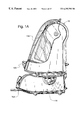
- FIG. 1A is a side view of the left side of the stackable reservoir housing stacked upon a scaler housing shown in FIG. 1 .
- FIG. 1B is a rear view of the stackable reservoir housing stacked upon a scaler housing shown in FIGS. 1 and 1A.
- FIG. 1C is a side view of the stackable reservoir housing in accordance with the invention shown in FIGS. 1-9 with the lid partially cut away.
- FIG. 2 is a front view of the stackable reservoir housing shown in FIGS. 1-9.
- FIG. 3 is a rear view of the stackable reservoir housing shown in FIGS. 1-9.
- FIG. 4 is a top view of the stackable reservoir housing shown in FIGS. 1-9.
- FIG. 5 is a bottom view of a stackable reservoir housing shown in FIGS. 1-9.
- FIG. 6 is a side view of a stackable reservoir housing shown in FIGS. 1-9 with its lid in open position.
- FIG. 7 is a top view of a stackable reservoir housing shown in FIGS. 1-9 with its lid in open position.
- FIG. 7A is a top view of a stackable reservoir housing shown in FIGS. 1-9 with its lid in open position with the lid partially cut away.
- FIG. 8 is a front view of a stackable reservoir housing shown in FIGS. 1-9 with its lid in open position.
- FIG. 9 is a rear view of the stackable reservoir housing shown in FIGS. 1-9 with its lid in open position.
- FIG. 10 is a top view of the scaler housing in accordance with the invention shown in FIGS. 10-13.
- FIG. 11 is a front view of the scaler housing shown in FIGS. 10-13.
- FIG. 12 is a side view of the scaler housing shown in FIGS. 10-13.
- FIG. 13 is a bottom view of the scaler housing shown in FIGS. 10-13.
- FIG. 14 is schematic diagram of the stacking dental reservoir and scaling system shown in FIGS. 1, 1 A and 1 B.
- FIGS. 14A, 14 B and 14 C are schematic diagrams of the air pressure/venting distribution valve (selector valve) in three different positions.
- FIG. 15 is a top view of a air polishing housing shown in FIGS. 15-18.
- FIG. 16 is a front view of the air polishing housing shown in FIGS. 15-18.
- FIG. 17 is a side view of the air polishing housing shown in FIGS. 15-18.
- FIG. 18 is a bottom view of the air polishing housing shown in FIGS. 15-18.
- FIG. 19 is a schematic diagram of the stacking dental reservoir shown in FIGS. 1 C and 2 - 9 in use with the air polishing system shown in FIGS. 15-18.
- FIG. 20 is a schematic diagram of a partial cross-sectional top view of a reservoir housing showing a cap for a container.
- An ultrasonic dental tooth treatment system including an ultrasonic dental handpiece, a fluid reservoir housing and a power control housing.
- the reservoir housing is supported by the control housing.
- the reservoir housing encloses two containers having input passages which are connected to the air pressurization and venting distribution selector valve.
- the container has output passages which are connected to a control housing conduit which is connected through a solenoid valve and flow control device to the handpiece.
- the control housing encloses a power generating (and/or control) circuit which is connected to the handpiece.
- a fluid dispenser includes a readily removable reservoir supported by a reservoir housing having a pivotable cover and a cover actuated fluid (pressurized air) interlock fluid control valve.
- the cover is pivotable between an open position and a closed position.
- the cover actuated interlock valve is closed by the cover when the cover is in its open position.
- the cover actuated interlock valve is in open position when the cover is in closed position.
- a fluid dispenser includes a readily removable container of the invention supported by a reservoir housing having housing fluid flow connectors (or couplings) a pivotable cover and an air pressure venting distribution fluid selector control valve.
- the container has a cap with a fluid and an air flow connector (or port).
- the housing connectors (or couplings) are connected to the cap connectors (or ports). Air pressure is supplied through one coupling to the reservoir and fluid exits from the same reservoir through another coupling.
- the seals on the coupling are so placed that upon removal of a reservoir, the seal on the air supply coupling disengages before the seal on the liquid coupling, thereby further venting the air pressure from the reservoir, and preventing leakage during disengagement of the reservoirs.
- the cover is pivotable between an open position and a closed position.
- An interlock valve is closed by the cover when the cover is in the open position thereby venting reservoir pressure and at the same time preventing air pressure from entering the reservoirs.
- the valve is open when the cover is in closed position. The cover in closed position prevents the cap from moving sufficiently for the cap connector to disengage from the housing connector.
- stacking dental reservoir and scaler system 10 includes a reservoir housing 12 and a scaler housing 14 and a handpiece 16 as shown in FIGS. 1 and 14.
- the scaler housing 14 is connected through fluid conveying conduit 18 to coupler 20 which has a shut-off valve.
- Coupler 20 is inserted in fluid type connection into coupler 22 which has a shut-off valve.
- Coupler 22 connects fluid conveying conduit 23 to conduit 18 .
- Conduit 18 is connected by couplers 20 A and 20 B through solenoid valve and flow control device to conduit 24 to convey fluid into ultrasonic handpiece 16 .
- Coupler with automatic shut-off valve 26 is adapted to be connected to a water supply, which preferably has a pressure of at least 10 psig.
- the water supply has a pressure of at least 20 psig. More preferably the water supply has the pressure of about 60 psig.
- Water is conveyed from the water supply through the coupler and shut off valve 26 through conduit 28 to air pilot valve 30 .
- Water is conveyed from air pilot valve 30 through conduit 32 into conduit 23 , and conduit 18 through a solenoid valve and flow control device into conduit 24 and into handpiece 16 .
- Conduits 34 and 36 have check valves 38 and 40 respectively and are connected to reservoir containers 42 and 44 respectively.
- Containers 42 and 44 have caps 41 and 43 respectively.
- Conduit 32 has check valve 87 and is connected to air pilot valve 30 .
- Coupler 52 which has an automatic shut-off valve, is connected to an air supply of pressurized air, which preferably is regulated to have an air pressure of about 100 psig. Coupler 52 is connected through conduit 54 to pressure regulator 56 . Pressure regulator 56 is connected through conduit 58 through interlock valve 60 . Valve 60 has a button 62 which must be pressed to open valve 60 . When button 62 is pressed, air is conveyed through valve 60 through conduit 64 to selector valve 50 . Coupler 66 which has an automatic shut-off valve is connected to conduit 68 . Conduit 68 is connected to conduit 54 . Coupler 66 provides a connection to pressurized air to operate other devices.
- Power control (or generator) 70 is connected to power source 72 through electrical conductor 74 and to power control 70 .
- Power control (or generator) 70 is connected to handpiece 16 through electrical conductor 76 .
- Feet 80 , 80 A, 82 and 82 A are connected to bottom wall 80 B of reservoir housing 12 .
- Feet 80 , 80 A, 82 and 82 A are supported in grooves 84 and 86 in the upper face of scaler housing 14 .
- Feet 80 and 82 are connected to the bottom of the reservoir housing 12 .
- Reservoir housing 12 has a cover 102 which is opened by pivoting around hinge 104 and 104 A.
- Knob 106 is connected by selector valve stem 106 A to valve 50 .
- Turning knob 106 to one side positions the valve 50 to convey fluid from one reservoir through conduit 18 .
- Turning knob 106 to center position vents air from air pilot valve, causing air pilot valve to open and thereby causing external water through conduit 18 .
- Feet 80 and 80 A are supported on groove 160 of scaler housing 14 .
- Feet 82 and 82 A are supported in groove 164 in the upper surface of scaler housing 14 .
- Grooves 160 and 164 prevent feet 80 , 80 A, 82 and 82 A from slipping in forward or reversed directions which are perpendicular to the central axis of the groove.
- Groove 162 is also provided in the upper surface of scaler housing 14 .
- Grooves 160 , 162 and 164 are also adapted for placement of handpiece 16 when reservoir housing 12 is not stacked upon scaler housing 14 .
- Holder 170 is adapted to hold handpiece 16 .
- Holder 170 is connected to scaler housing 14 .
- Knob 158 is connected by valve stem 158 A to fluid flow control valve 158 B.
- Knob 156 is connected by electrical conductor 156 A to power control 70 .
- caps 41 and 43 are held by lid 102 onto the adjacent fluid connectors 42 A and 44 A as shown in FIGS. 1A and 7A.
- Scaler housing 14 is supported by feet 180 , 180 A, 182 and 182 A.
- Vents 198 , 200 , 202 , 204 and 206 in the lower wall of scaler housing 14 allow cooling by convection.
- Fluid conduit 24 and electrical conductor 76 are enclosed by flexible plastic conduit 76 A.
- Conduit 20 connected to connector 22 at one end and at the other end to connector 192 .
- Foot switch 170 A is connected by electrical current conductor 170 B to power control 70 .
- valve 50 is rotated to three different positions by turning knob 106 .
- FIG. 14A by turning valve 50 to the position shown air entering valve 50 through line 64 leaves valve 50 through line 56 to pressurize container 42 causing fluid to flow from container 42 through line 34 .
- FIG. 14B by positioning valve 50 in the position shown, air enters valve 50 through line 46 and leave valve 50 through line 48 . Air in line 48 pressurizes container 44 causing fluid from container 44 to flow through line 36 .
- FIG. 14C by positioning valve 50 as shown, neither container 42 nor container 44 is pressurized, and fluid does not flow from either container in this position of valve 50 . Rather in the position of valve 50 shown in FIG. 14C, air pressure is not supplied to valve 30 and existing air pressure is reduced by a bleed port, opening air pilot valve 30 allowing fluid to flow through line 28 to line 32 , as shown in FIG. 14 .
- air polishing housing 314 is connected to polishing handpiece 316 .
- Air polishing base housing 314 has grooves 360 and 364 in the upper face thereof. Feet 80 and 82 of reservoir housing are positioned in grooves 360 and 364 of the upper face of the air polishing housing when the reservoir base housing 314 is in stacked position on the air polishing housing.
- Outer container 390 has container cap 390 A. Powder container 390 is connected through a conduit 394 to coupler 66 to provide air pressure in powder container 390 . Powder from powder container 390 is conveyed under pressure through conduit 392 to handpiece 316 . Fluid is conveyed through line 18 to air polishing base housing 314 .
- Handpiece 316 is provided with a mixing tip 316 A which sprays liquid from an outer concentric orifice and sprays powder from an inner-circular orifice. Thus, it provides an annulus of liquid around a circular stream of powder which mixes in the spray prior to polishing the tooth surface.
- Conduits 392 and 324 are enclosed by flexible plastic cover 376 A.
- Polishing base is supported by feet 380 , 382 , 380 A and 382 A.
- the lower face of air polishing base housing 314 has vent 398 , 400 , 402 , 404 and 406 .
- Handpiece 316 is adapted to be held by holder 370 .
- Knobs 356 and 358 are connected to a variable power control unit, and a fluid flow control valve respectively.
- Knob 358 is connected by valve stem 358 A to fluid flow control valve 358 B.
- Connectors (or couplings) 504 and 505 are connected in fluid flow communication with connectors (or couplings) 506 and 508 respectively.
- Connector 506 is connected in fluid flow communication with conduit 46 .
- Connector 508 is connected in fluid flow communication with conduit 34 .
- reservoir housing 12 has a height from the rounded top end to the bottom end, a width from side to side (the sides are parallel), a lower depth from front to back at the bottom end, a middle depth from front to back at the midpoint of the height and an upper depth from front to back at the center of the rounded top end.
- the reservoir housing height is greater than the width.
- the reservoir housing lower depth is greater than the upper depth.
- the reservoir housing upper depth is greater than the middle depth.
Abstract
An ultrasonic dental tooth treatment system including an ultrasonic dental handpiece, a fluid reservoir housing and a power control housing. The reservoir housing is supported by the control housing. The reservoir housing encloses two containers which are connected to the selector valve. The selector valve is connected to a control housing conduit which is connected to the handpiece. The control housing encloses a power control circuit which is connected to the handpiece. In a preferred embodiment of the invention a fluid dispenser includes at least one readily removable reservoir container supported by a reservoir housing having a pivotable cover and a fluid control valve. The cover is pivotable between an open position and a closed position. The valve is closed by the cover when the cover is in its open position.
Description
This application is a continuation of application Ser. No. 08/723,199, filed Sep. 27, 1996 now U.S. Pat. No. 6,030,212.
The invention relates to dental scaling systems. The invention provides a stacking dental reservoir and scaling system. The present invention provides a reservoir housing having at least one container which is readily connected to a power control housing and stackable thereon. The level of liquid in each container in the reservoir housing is readily visually inspected through a clear plastic (polymeric) cover. The cover pivots on hinges to swing the lower end of the cover above the reservoir housing to open the housing for removal and/or installation of containers.
It is an object of the invention to provide an ultrasonic dental tooth treatment system including an ultrasonic dental handpiece and attaching cable assembly and control housing and a fluid reservoir housing which encloses two containers, each connected to a selector valve connected to a control housing conduit connected to a handpiece conduit.
It is an object of the invention to provide a fluid dispenser which includes readily removable reservoir supported by a reservoir housing having a cover which is pivotable between an open position and a closed position and an interlock valve which is closed by the cover when the cover is in its open position.
It is an object of the invention to provide a stacking dental reservoir and scaling system.
It is an object of the invention to provide a dental scaler system having a reservoir housing with a clear plastic cover which pivots on hinges to swing the lower end of the cover above the reservoir housing to open the housing for the removal and/or installation of containers, as is provided by the present invention.
It is an object of the invention to provide a stackable reservoir housing having a self contained three position selector valve connected in fluid flow communication to a source of air pressure for dispensing from either of two reservoir liquid containers or from a water supply through the selector valve. In a preferred embodiment of the invention only fluid from any one of the containers is conveyed to the handpiece and the system is not connected to an external water supply. By so doing the system can dispense clean water. The system can also be connected to an external water supply, which can also be dispensed to a scaler system.
Warrin et al in U.S. Pat. No. 5,419,703 discloses a method of subgingival scaling and lavage. The apparatus disclosed in Warrin et al includes reservoirs for storing medicament inside a base unit.
The invention solves the problems of the prior art fluid dispensing dental system.
FIG. 1 is a side view of the right side of a stackable reservoir housing stacked upon a scaler housing in accordance with the invention.
FIG. 1A is a side view of the left side of the stackable reservoir housing stacked upon a scaler housing shown in FIG. 1.
FIG. 1B is a rear view of the stackable reservoir housing stacked upon a scaler housing shown in FIGS. 1 and 1A.
FIG. 1C is a side view of the stackable reservoir housing in accordance with the invention shown in FIGS. 1-9 with the lid partially cut away.
FIG. 2 is a front view of the stackable reservoir housing shown in FIGS. 1-9.
FIG. 3 is a rear view of the stackable reservoir housing shown in FIGS. 1-9.
FIG. 4 is a top view of the stackable reservoir housing shown in FIGS. 1-9.
FIG. 5 is a bottom view of a stackable reservoir housing shown in FIGS. 1-9.
FIG. 6 is a side view of a stackable reservoir housing shown in FIGS. 1-9 with its lid in open position.
FIG. 7 is a top view of a stackable reservoir housing shown in FIGS. 1-9 with its lid in open position.
FIG. 7A is a top view of a stackable reservoir housing shown in FIGS. 1-9 with its lid in open position with the lid partially cut away.
FIG. 8 is a front view of a stackable reservoir housing shown in FIGS. 1-9 with its lid in open position.
FIG. 9 is a rear view of the stackable reservoir housing shown in FIGS. 1-9 with its lid in open position.
FIG. 10 is a top view of the scaler housing in accordance with the invention shown in FIGS. 10-13.
FIG. 11 is a front view of the scaler housing shown in FIGS. 10-13.
FIG. 12 is a side view of the scaler housing shown in FIGS. 10-13.
FIG. 13 is a bottom view of the scaler housing shown in FIGS. 10-13.
FIG. 14 is schematic diagram of the stacking dental reservoir and scaling system shown in FIGS. 1, 1A and 1B.
FIGS. 14A, 14B and 14C are schematic diagrams of the air pressure/venting distribution valve (selector valve) in three different positions.
FIG. 15 is a top view of a air polishing housing shown in FIGS. 15-18.
FIG. 16 is a front view of the air polishing housing shown in FIGS. 15-18.
FIG. 17 is a side view of the air polishing housing shown in FIGS. 15-18.
FIG. 18 is a bottom view of the air polishing housing shown in FIGS. 15-18.
FIG. 19 is a schematic diagram of the stacking dental reservoir shown in FIGS. 1C and 2-9 in use with the air polishing system shown in FIGS. 15-18.
FIG. 20 is a schematic diagram of a partial cross-sectional top view of a reservoir housing showing a cap for a container.
An ultrasonic dental tooth treatment system including an ultrasonic dental handpiece, a fluid reservoir housing and a power control housing. The reservoir housing is supported by the control housing. The reservoir housing encloses two containers having input passages which are connected to the air pressurization and venting distribution selector valve. The container has output passages which are connected to a control housing conduit which is connected through a solenoid valve and flow control device to the handpiece. The control housing encloses a power generating (and/or control) circuit which is connected to the handpiece. In a preferred embodiment of the invention a fluid dispenser includes a readily removable reservoir supported by a reservoir housing having a pivotable cover and a cover actuated fluid (pressurized air) interlock fluid control valve. The cover is pivotable between an open position and a closed position. The cover actuated interlock valve is closed by the cover when the cover is in its open position. The cover actuated interlock valve is in open position when the cover is in closed position.
A fluid dispenser includes a readily removable container of the invention supported by a reservoir housing having housing fluid flow connectors (or couplings) a pivotable cover and an air pressure venting distribution fluid selector control valve. The container has a cap with a fluid and an air flow connector (or port). The housing connectors (or couplings) are connected to the cap connectors (or ports). Air pressure is supplied through one coupling to the reservoir and fluid exits from the same reservoir through another coupling. The seals on the coupling are so placed that upon removal of a reservoir, the seal on the air supply coupling disengages before the seal on the liquid coupling, thereby further venting the air pressure from the reservoir, and preventing leakage during disengagement of the reservoirs. The cover is pivotable between an open position and a closed position. An interlock valve is closed by the cover when the cover is in the open position thereby venting reservoir pressure and at the same time preventing air pressure from entering the reservoirs. The valve is open when the cover is in closed position. The cover in closed position prevents the cap from moving sufficiently for the cap connector to disengage from the housing connector.
The position at the pivots, about which the cover rotates, is located below the contact point between the container caps and the cover. When either container is pressurized the force of the container cap against the cover thereby causes the cover to be forced into a closed position.
The invention is now described with more particular reference to FIGS. 1-19. It is seen that stacking dental reservoir and scaler system 10 includes a reservoir housing 12 and a scaler housing 14 and a handpiece 16 as shown in FIGS. 1 and 14. The scaler housing 14 is connected through fluid conveying conduit 18 to coupler 20 which has a shut-off valve. Coupler 20 is inserted in fluid type connection into coupler 22 which has a shut-off valve. Coupler 22 connects fluid conveying conduit 23 to conduit 18. Conduit 18 is connected by couplers 20A and 20B through solenoid valve and flow control device to conduit 24 to convey fluid into ultrasonic handpiece 16.
Coupler with automatic shut-off valve 26 is adapted to be connected to a water supply, which preferably has a pressure of at least 10 psig. Preferably, the water supply has a pressure of at least 20 psig. More preferably the water supply has the pressure of about 60 psig. Water is conveyed from the water supply through the coupler and shut off valve 26 through conduit 28 to air pilot valve 30. Water is conveyed from air pilot valve 30 through conduit 32 into conduit 23, and conduit 18 through a solenoid valve and flow control device into conduit 24 and into handpiece 16. Conduits 34 and 36 have check valves 38 and 40 respectively and are connected to reservoir containers 42 and 44 respectively. Containers 42 and 44 have caps 41 and 43 respectively. Conduit 32 has check valve 87 and is connected to air pilot valve 30.
Power control (or generator) 70 is connected to power source 72 through electrical conductor 74 and to power control 70. Power control (or generator) 70 is connected to handpiece 16 through electrical conductor 76.
When lid 102 is in closed position, caps 41 and 43 are held by lid 102 onto the adjacent fluid connectors 42A and 44A as shown in FIGS. 1A and 7A.
Foot switch 170A is connected by electrical current conductor 170B to power control 70.
As shown in FIGS. 14, 14A, 14B and 14 C valve 50 is rotated to three different positions by turning knob 106. As shown in FIG. 14A by turning valve 50 to the position shown air entering valve 50 through line 64 leaves valve 50 through line 56 to pressurize container 42 causing fluid to flow from container 42 through line 34. As shown in FIG. 14B by positioning valve 50 in the position shown, air enters valve 50 through line 46 and leave valve 50 through line 48. Air in line 48 pressurizes container 44 causing fluid from container 44 to flow through line 36. As shown in FIG. 14C by positioning valve 50 as shown, neither container 42 nor container 44 is pressurized, and fluid does not flow from either container in this position of valve 50. Rather in the position of valve 50 shown in FIG. 14C, air pressure is not supplied to valve 30 and existing air pressure is reduced by a bleed port, opening air pilot valve 30 allowing fluid to flow through line 28 to line 32, as shown in FIG. 14.
With more particular reference to FIGS. 15-19, it is seen that air polishing housing 314 is connected to polishing handpiece 316. Air polishing base housing 314 has grooves 360 and 364 in the upper face thereof. Feet 80 and 82 of reservoir housing are positioned in grooves 360 and 364 of the upper face of the air polishing housing when the reservoir base housing 314 is in stacked position on the air polishing housing. Outer container 390 has container cap 390A. Powder container 390 is connected through a conduit 394 to coupler 66 to provide air pressure in powder container 390. Powder from powder container 390 is conveyed under pressure through conduit 392 to handpiece 316. Fluid is conveyed through line 18 to air polishing base housing 314. Fluid is conveyed from air polishing 314 through conduit 324 to handpiece 316. Handpiece 316 is provided with a mixing tip 316A which sprays liquid from an outer concentric orifice and sprays powder from an inner-circular orifice. Thus, it provides an annulus of liquid around a circular stream of powder which mixes in the spray prior to polishing the tooth surface. Conduits 392 and 324 are enclosed by flexible plastic cover 376A. Polishing base is supported by feet 380, 382, 380A and 382A. The lower face of air polishing base housing 314 has vent 398, 400, 402, 404 and 406. Handpiece 316 is adapted to be held by holder 370. Knobs 356 and 358 are connected to a variable power control unit, and a fluid flow control valve respectively. Knob 358 is connected by valve stem 358A to fluid flow control valve 358B.
Upon disengaging reservoir cap 41 from housing 12, O-ring 500 unseals relieving any residual air pressure in container 42, with further outward movement of the cap, O-ring 501 is unseated, and a vent hole is exposed to atmospheric pressure, thereby allowing any fluid remaining in the passageway of the coupler to move back into container 42 avoiding spillage during final withdrawal of cap 41 and container 42 from housing 12 past O-ring 501. Connectors (or couplings) 504 and 505 are connected in fluid flow communication with connectors (or couplings) 506 and 508 respectively. Connector 506 is connected in fluid flow communication with conduit 46. Connector 508 is connected in fluid flow communication with conduit 34.
As shown in FIGS. 1, 1A and 1 B reservoir housing 12 has a height from the rounded top end to the bottom end, a width from side to side (the sides are parallel), a lower depth from front to back at the bottom end, a middle depth from front to back at the midpoint of the height and an upper depth from front to back at the center of the rounded top end. The reservoir housing height is greater than the width. The reservoir housing lower depth is greater than the upper depth. The reservoir housing upper depth is greater than the middle depth.
It will be apparent to those skilled in the art that various modifications and changes may be made in the practice and use of the present invention without departing from the scope thereof as set forth in the following claims.
Claims (17)
1. A stacking system comprising:
a reservoir housing,
a base housing and
an ultrasonic dental handpiece having an electrically conducting coil,
said reservoir housing supporting a readily removable first container said reservoir housing having feet,
said reservoir housing having a base end connected to said feet,
said reservoir housing being supported by and positioned above said base housing, said base housing having an upper face, said upper face having grooves, said feet being positioned in said grooves, said first container being in fluid flow communication with said handpiece.
2. The system of claim 1 wherein said first container is connected through conduit means to a valve.
3. The system of claim 2 wherein said valve is connected through a conduit to a source of air at a pressure of at least 35 psi.
4. The system of claim 2 wherein said reservoir housing supports a second readily removable container, said second container being connected through a conduit to said valve.
5. The system of claim 1 wherein said base housing encloses a base housing conduit.
6. The system of claim 5 wherein said base housing conduit is connected to a base housing connector, said base housing connector being connected to said base connecting conduit.
7. The system of claim 1 wherein said first container encloses a fluid, said fluid comprising medicament.
8. The system of claim 7 wherein said reservoir housing further comprises a cover and said first container is enclosed by said reservoir housing when said cover is in closed position.
9. The system of claim 1 wherein said base housing encloses a power control circuit, said power control circuit is connected to said coil in said handpiece,
said reservoir housing has a cover consisting essentially of clear transparent plastic,
said first container has a first container fluid flow connector, said reservoir housing has a first reservoir fluid flow connector, said first reservoir housing connector engages said first container connector,
said reservoir housing has a base end and a hinge end, said base end is connected to said feet, said hinge end is substantially opposite to said base end, said hinge end supporting a hinge, said hinge end is connected to said first and second housing fluid flow connector,
said cover is connected to said hinge, said cover is positioned against said first container to prevent movement of said first container whereby said first container connector is held in said first reservoir connector, while said cover is in closed position.
10. A method of using a dental scaler comprising:
providing a stacking system a reservoir housing, having a base housing and an ultrasonic dental handpiece having an electrically conducting coil and a scaling tip, said reservoir housing supporting a readily removable first container said reservoir housing having feet, said reservoir housing having a base end connected to said feet, said reservoir housing being supported by and positioned above said base housing, said base housing having an upper face, said upper face having grooves, said feet being positioned in said grooves, said first container being in fluid flow communication with said handpiece, and
scaling a tooth with said tip.
11. A reservoir system comprising:
a reservoir housing,
a cover consisting essentially of clear transparent plastic,
said reservoir housing supporting a first and a second readily removable container,
each said container being in fluid flow communication with a source of pressurized air,
said reservoir housing having a rounded top end supporting a hinge, said cover having a rounded end and an opposite end, said cover rounded end being connected to said hinge, said cover being pivotable between a closed position and an open position with said opposite end of said cover above the reservoir housing allowing for removal of said first and second container, said cover in closed position preventing said containers from moving sufficiently,
said reservoir housing having a height, a width, a lower depth and an upper depth, said reservoir housing height being greater than said reservoir housing width, said reservoir housing lower depth being greater than said reservoir housing upper depth.
12. The system of claim 11 wherein said reservoir housing has a middle depth and said reservoir housing upper depth is greater than said reservoir housing middle depth.
13. The system of claim 11 further comprising a first cap connected to said first container and a second cap connected to said second container, a first and second conduit, said first conduit being enclosed by said reservoir housing and connected in fluid flow communication through said first cap to said first container, said second conduit being enclosed by said reservoir housing and connected in fluid flow communication through said second cap to said second container.
14. The system of claim 13 further comprising a first coupler and a base housing, said base housing supporting a second coupler, and wherein said first coupler is connected in fluid flow communication to said second coupler, said first conduit is connected in fluid flow communication to said first coupler, said second conduit is connected in fluid flow communication to said first coupler.
15. The system of claim 14 further comprising an ultrasonic
handpiece having a handpiece conduit and
wherein said base housing encloses a base conduit
said base conduit being connected in fluid flow communication to said handpiece conduit and
said base conduit being connected in fluid flow communication to said second coupler.
16. The system of claim 11 wherein said reservoir housing supports a
first, a second, a third and a fourth housing fluid flow connector,
said first cap has a first and a second cap fluid flow connector,
said second cap has a third and a fourth cap fluid flow connector,
said first housing fluid flow connector is connected in fluid flow communication to said first cap connector,
said second housing fluid flow connector is connected in fluid flow communication to said second cap connector,
said third housing connector is connected in fluid flow communication to said third cap connector, and
said fourth housing connector is connected in fluid flow communication to said fourth cap connector.
17. A method of using a dental scaler comprising:
providing a dental scaler having a reservoir housing, a base housing and an ultrasonic dental handpiece having an electrically conducting coil and a scaling tip,
said reservoir housing, and a cover,
said reservoir housing supporting a first and a second readily removable container,
said reservoir housing having a rounded top end supporting a hinge, said cover having a rounded end and an opposite end, said cover rounded end being connected to said hinge, said cover being pivotable between a closed position and an open position with said opposite end of said cover above the reservoir housing allowing for removal of said first and second container, said cover in closed position preventing said containers from moving sufficiently,
said reservoir housing having a height, a width, a lower depth and an upper depth, said reservoir housing height being greater than said reservoir housing width, said reservoir housing lower depth being greater than said reservoir housing upper depth,
said first container being in fluid flow communication with said handpiece, and
scaling a tooth with said tip.
Priority Applications (1)
| Application Number | Priority Date | Filing Date | Title |
|---|---|---|---|
| US09/407,438 US6293793B1 (en) | 1996-09-27 | 1999-09-29 | Stackable reservoir and scaler system |
Applications Claiming Priority (2)
| Application Number | Priority Date | Filing Date | Title |
|---|---|---|---|
| US08/723,199 US6030212A (en) | 1996-09-27 | 1996-09-27 | Stacking reservoir and scaler system |
| US09/407,438 US6293793B1 (en) | 1996-09-27 | 1999-09-29 | Stackable reservoir and scaler system |
Related Parent Applications (1)
| Application Number | Title | Priority Date | Filing Date |
|---|---|---|---|
| US08/723,199 Continuation US6030212A (en) | 1996-09-27 | 1996-09-27 | Stacking reservoir and scaler system |
Publications (1)
| Publication Number | Publication Date |
|---|---|
| US6293793B1 true US6293793B1 (en) | 2001-09-25 |
Family
ID=24905267
Family Applications (2)
| Application Number | Title | Priority Date | Filing Date |
|---|---|---|---|
| US08/723,199 Expired - Lifetime US6030212A (en) | 1996-09-27 | 1996-09-27 | Stacking reservoir and scaler system |
| US09/407,438 Expired - Lifetime US6293793B1 (en) | 1996-09-27 | 1999-09-29 | Stackable reservoir and scaler system |
Family Applications Before (1)
| Application Number | Title | Priority Date | Filing Date |
|---|---|---|---|
| US08/723,199 Expired - Lifetime US6030212A (en) | 1996-09-27 | 1996-09-27 | Stacking reservoir and scaler system |
Country Status (9)
| Country | Link |
|---|---|
| US (2) | US6030212A (en) |
| EP (1) | EP0935445B1 (en) |
| JP (1) | JP3999272B2 (en) |
| KR (1) | KR100498134B1 (en) |
| CA (1) | CA2266727C (en) |
| DE (1) | DE69722804T2 (en) |
| ES (1) | ES2196373T3 (en) |
| TW (1) | TW418082B (en) |
| WO (1) | WO1998012980A1 (en) |
Cited By (6)
| Publication number | Priority date | Publication date | Assignee | Title |
|---|---|---|---|---|
| US6450811B1 (en) * | 1999-09-24 | 2002-09-17 | Dentsply Research & Development Corp. | Dental scaler system and method |
| US20050095555A1 (en) * | 2003-10-31 | 2005-05-05 | Guaragno Kenneth R. | Dental scaler system and method |
| US20050227201A1 (en) * | 2004-04-08 | 2005-10-13 | Pond Gary J | Irrigation tip adaptor for ultrasonic handpiece |
| US20080146991A1 (en) * | 2006-12-18 | 2008-06-19 | Chris Hernandez | Hand operated dispenser for surgical irrigation fluids |
| US20080233540A1 (en) * | 2007-03-19 | 2008-09-25 | Olivier Olmo | Powder blast tool, powder reservoir, insert for powder reservoir and method of dental treatment |
| US20100000533A1 (en) * | 2008-07-03 | 2010-01-07 | Melanie Schmid | Dental treatment apparatus |
Families Citing this family (9)
| Publication number | Priority date | Publication date | Assignee | Title |
|---|---|---|---|---|
| US6030212A (en) * | 1996-09-27 | 2000-02-29 | Dentsply Research & Development Corp. | Stacking reservoir and scaler system |
| USD433137S (en) * | 1999-10-18 | 2000-10-31 | Dentsply Research & Development Corp. | Dental scaler |
| ES2568957T3 (en) * | 1999-12-20 | 2016-05-05 | Dentsply International, Inc. | Dental scraper system |
| US6716028B2 (en) * | 2000-08-04 | 2004-04-06 | Hu-Friedy Mfg. Co., Inc. | Ultrasonic swivel insert |
| US6811399B2 (en) | 2001-07-27 | 2004-11-02 | Hu-Friedy Mfg. Co., Inc. | Torque lock for ultrasonic swivelable inserts and method |
| US7226288B2 (en) * | 2003-03-13 | 2007-06-05 | Discus Dental Impressions, Inc. | Apparatus for evacuation of root canal |
| US20090004621A1 (en) * | 2007-06-27 | 2009-01-01 | Nancy Quan | Endodontic Irrigation System |
| CA2806864A1 (en) * | 2010-11-29 | 2012-06-07 | Dentsply International Inc. | Dental laser-emitting device and methods |
| EP3202364B1 (en) * | 2016-02-04 | 2022-08-10 | Ferton Holding S.A. | Powder chamber, station for a powder chamber and method to operated a powder polishing device |
Citations (93)
| Publication number | Priority date | Publication date | Assignee | Title |
|---|---|---|---|---|
| US2874470A (en) | 1954-05-28 | 1959-02-24 | James R Richards | High frequency dental tool |
| US3075288A (en) | 1954-12-24 | 1963-01-29 | Cavitron Ultrasonics Inc | Dental instrument |
| US3077415A (en) | 1960-06-22 | 1963-02-12 | Cementation Co Ltd | Mechanical rendering of surfaces and pointing of brick work |
| US3091033A (en) | 1961-06-02 | 1963-05-28 | Irving A Ellman | Dental cleaning tool, apparatus, and method |
| US3213537A (en) | 1954-12-24 | 1965-10-26 | Cavitron Corp | Supply and control apparatus for vibratory cutting device |
| US3368280A (en) | 1966-03-23 | 1968-02-13 | C & B Inc | Dental tool |
| US3375583A (en) | 1966-03-10 | 1968-04-02 | C & B Inc | Ultrasonic dental tool |
| US3433226A (en) | 1965-07-21 | 1969-03-18 | Aeroprojects Inc | Vibratory catheterization apparatus and method of using |
| US3488851A (en) | 1968-04-18 | 1970-01-13 | Zoltan Haydu | Ultrasonic devices |
| US3518766A (en) | 1969-01-30 | 1970-07-07 | Emanuel Burt | Piezoelectric cleaning device with removable workpiece |
| US3526036A (en) | 1968-04-01 | 1970-09-01 | Sven Karl Lennart Goof | Ultrasonic dental apparatus |
| US3589012A (en) | 1969-06-30 | 1971-06-29 | C & B Corp | Tip for ultrasonic dental instrument |
| US3593425A (en) | 1969-09-10 | 1971-07-20 | Hydrosonic Corp | Electric ultrasonic tooth-cleaning apparatus |
| US3593423A (en) | 1969-04-18 | 1971-07-20 | Pelton & Crane Co | Multipurpose dental syringe apparatus |
| US3631631A (en) | 1970-01-21 | 1972-01-04 | Dental Gold Co | Pneumatic abrasive cutting apparatus |
| US3636947A (en) | 1970-12-03 | 1972-01-25 | Ultrasonic Systems | Ultrasonic home dental instrument and method |
| US3645255A (en) | 1970-02-02 | 1972-02-29 | Hydrosonic Corp | Ultrasonic tooth-cleaning apparatus |
| US3654502A (en) | 1970-06-24 | 1972-04-04 | Countronic Corp | Ultrasonic tool |
| US3693613A (en) | 1970-12-09 | 1972-09-26 | Cavitron Corp | Surgical handpiece and flow control system for use therewith |
| US3703037A (en) | 1970-06-25 | 1972-11-21 | Seymour Robinson | Ultrasonic dental hand-piece with detachable treatment tools |
| US3718973A (en) | 1970-05-01 | 1973-03-06 | R Slater | Dental system |
| US3760799A (en) | 1972-03-02 | 1973-09-25 | D Crowson | Sonic teeth-cleaning apparatus and method |
| US3807048A (en) | 1972-01-03 | 1974-04-30 | O Malmin | Combined irrigator, injector and evacuator |
| US3809977A (en) | 1971-02-26 | 1974-05-07 | Ultrasonic Systems | Ultrasonic kits and motor systems |
| US3858358A (en) | 1973-01-02 | 1975-01-07 | American Aero Ind | High pressure liquid and abrasive cleaning apparatus |
| US3863628A (en) | 1972-06-12 | 1975-02-04 | Nat Patent Dev Corp | Dental treatment method and apparatus |
| US3864472A (en) | 1972-11-06 | 1975-02-04 | Colgate Palmolive Co | Clear lemon-flavored mouthwash |
| US3882638A (en) | 1973-10-04 | 1975-05-13 | Robert B Black | Air-abrasive prophylaxis equipment |
| US3887701A (en) | 1974-11-01 | 1975-06-03 | Colgate Palmolive Co | Antibacterial oral compositions containing preservative-antioxidants |
| US3924335A (en) | 1971-02-26 | 1975-12-09 | Ultrasonic Systems | Ultrasonic dental and other instrument means and methods |
| US3924806A (en) | 1974-11-20 | 1975-12-09 | Ford Motor Co | Mixing manifold for air atomizing spray apparatus |
| US3930173A (en) | 1971-06-15 | 1975-12-30 | Surgical Design Corp | Ultrasonic transducers |
| US3956826A (en) | 1974-03-19 | 1976-05-18 | Cavitron Corporation | Ultrasonic device and method |
| US3972123A (en) | 1973-10-04 | 1976-08-03 | Black Robert B | Air-abrasive prophylaxis equipment |
| US3976222A (en) | 1974-01-28 | 1976-08-24 | Joseph Spagnolo | Beverage metering and dispensing device |
| US4012842A (en) | 1972-06-12 | 1977-03-22 | National Patent Development Corporation | Dental treatment method and apparatus |
| US4051337A (en) | 1976-01-27 | 1977-09-27 | Cavitron Corporation | Dental handpiece switch |
| USRE29687E (en) | 1973-05-29 | 1978-07-04 | Air-vibrator dental scaler | |
| US4116239A (en) | 1974-06-14 | 1978-09-26 | Ewen Sol J | Ultrasonic oxygenation instrument |
| US4148309A (en) | 1977-06-03 | 1979-04-10 | Reibel Peter R | Personal hygiene device |
| US4160821A (en) | 1978-02-27 | 1979-07-10 | Johnson & Johnson | Treatment for gingivitis |
| US4162576A (en) | 1976-03-24 | 1979-07-31 | Lion Hamigaki Kabushiki Kaisha | Appliances for treating teeth |
| US4184064A (en) | 1977-11-28 | 1980-01-15 | Amark Industries, Inc. | Water heating means |
| US4193197A (en) | 1976-07-06 | 1980-03-18 | Aquasonic Products Corp. | Fluid supply unit and systems for dental and medical instruments |
| US4193196A (en) | 1976-07-06 | 1980-03-18 | Aquasonic Products Corp. | Fluid supply unit for dental instruments |
| US4215476A (en) * | 1977-03-25 | 1980-08-05 | Armstrong Alexander S | Health services combination irrigator and aspirator |
| US4247288A (en) | 1976-06-18 | 1981-01-27 | Ricoh Watch Co., Ltd. | Method and apparatus for root canal irrigation |
| US4248379A (en) | 1979-08-16 | 1981-02-03 | Nordson Corporation | Powder spray color change system |
| US4249901A (en) | 1977-11-24 | 1981-02-10 | Medtronic Gmbh | Tooth treatment apparatus |
| USRE30536E (en) | 1978-05-01 | 1981-03-03 | Cavitron Corporation | Ultrasonic device and method |
| US4260380A (en) | 1979-04-02 | 1981-04-07 | Syntex (U.S.A.) Inc. | Vibratory device with fluid transport means |
| US4276024A (en) | 1977-03-28 | 1981-06-30 | Cavitron Corporation | Control systems for dental handpieces |
| US4276880A (en) | 1978-09-14 | 1981-07-07 | Oscar Malmin | Cannula and process |
| US4283174A (en) | 1979-11-05 | 1981-08-11 | Sertich Anthony T | Dental scaler having scaling tip particularly suitable for circular or ellipsoidal patterns of vibration |
| US4283175A (en) | 1979-11-05 | 1981-08-11 | Syntex (U.S.A.) Inc. | Dental scaler having scaling tip with rounded edge work surfaces particularly suitable for circular or ellipsoidal patterns of vibration |
| US4291017A (en) | 1979-11-19 | 1981-09-22 | Dental Concepts, Inc. | Method for limiting adherence of plaque and dental composition therefor |
| US4295827A (en) | 1979-12-31 | 1981-10-20 | Howard Martin | Endodontic flow through ultrasonic instrument holder attachment |
| US4302186A (en) | 1979-11-23 | 1981-11-24 | Teledyne Industries, Inc. | Oral hygiene appliances |
| US4302481A (en) | 1978-11-14 | 1981-11-24 | Gema Ag | Spray method and spray device, particularly for the spray-coating of articles with powder |
| US4315742A (en) | 1979-11-05 | 1982-02-16 | Syntex (U.S.A.) Inc. | Vibratory device having tool assembly with fluid transport means |
| US4330278A (en) | 1980-06-30 | 1982-05-18 | Howard Martin | Endodontic flow-through ultrasonic instrument holder device |
| US4332558A (en) | 1980-05-20 | 1982-06-01 | Lustig Leopold P | Dental scaling apparatus |
| US4339432A (en) | 1979-06-20 | 1982-07-13 | Lever Brothers Company | Oral mouthwash containing zinc and glycine |
| US4370131A (en) | 1977-06-24 | 1983-01-25 | Surgical Design | Ultrasonic transducer tips |
| US4428748A (en) | 1980-04-09 | 1984-01-31 | Peyman Gholam A | Combined ultrasonic emulsifier and mechanical cutter for surgery |
| US4453919A (en) | 1981-04-24 | 1984-06-12 | Micron Co., Ltd. | Dental scaler |
| US4472373A (en) | 1983-05-09 | 1984-09-18 | The Procter & Gamble Company | Oral compositions |
| US4487582A (en) | 1983-02-18 | 1984-12-11 | Cooper Lasersonics, Inc. | Dental cleaning system |
| US4490114A (en) | 1980-01-21 | 1984-12-25 | Cooper Lasersonics, Inc. | Ultrasonically driven low-speed rotary motor |
| US4492574A (en) | 1983-04-15 | 1985-01-08 | Cavitron, Inc. | Ultrasonic endodontic dental apparatus |
| US4505676A (en) | 1983-09-30 | 1985-03-19 | Dentsply Research & Development Corp. | Endodontic unit |
| US4522806A (en) | 1980-10-10 | 1985-06-11 | Lever Brothers Company | Oral compositions for hexetidine and zinc salts for the synergistic inhibition of dental plaque |
| US4582702A (en) | 1983-05-31 | 1986-04-15 | L'oreal | Cleaning product for dental and oral care, containing a non-ionic poly(hydroxypropyl ether) surface-active agent |
| US4592728A (en) | 1981-12-07 | 1986-06-03 | Davis Dennis R | Periodontal lavage delivery system |
| US4601900A (en) | 1984-03-29 | 1986-07-22 | Orion-Yhtyma Oy Fermion | Mouthwash composition and a method for preparing it |
| US4644937A (en) | 1983-05-03 | 1987-02-24 | Gimelli & Co. Ag | Mouth and tooth spray apparatus |
| US4682949A (en) | 1985-07-12 | 1987-07-28 | Dentsply Research & Development Corp. | Tool holder for ultrasonic endodontic apparatus |
| WO1987004613A1 (en) | 1986-02-07 | 1987-08-13 | National Patent Dental Products, Inc. | Apparatus and method for supplying heated liquid |
| US4731019A (en) | 1984-06-04 | 1988-03-15 | Howard Martin | Diamond coated scaler dental instrument for ultrasonic operation |
| US4770632A (en) | 1985-12-30 | 1988-09-13 | National Patent Development Corporation | Delivery system for dental treatment solution |
| US4820152A (en) | 1987-04-21 | 1989-04-11 | Dentsply Research & Development Corp. | Single multi-function handpiece for dental instruments |
| US4850868A (en) | 1987-07-13 | 1989-07-25 | Dentsply Research & Development Corp. | Spray shield |
| USD308566S (en) * | 1988-04-25 | 1990-06-12 | Innocorp Manufacturing, Inc. | Dispenser housing for the release of chemicals into a toilet bowl basin |
| US5060825A (en) | 1990-05-04 | 1991-10-29 | Sultan Chemists, Inc. | Irrigation system and method for delivering a selected one of multiple liquid solutions to a treatment site |
| US5087198A (en) | 1988-09-30 | 1992-02-11 | Castellini S.P.A. | Dental surgery apparatus capable of supplying three separate fluids to connected instruments |
| US5125837A (en) | 1988-01-06 | 1992-06-30 | Dentsply Management Corp. | Apparatus and method for therapeutic lavage and scaling of teeth |
| US5199604A (en) | 1990-05-04 | 1993-04-06 | Sultan Chemists, Inc. | Irrigation system and method for delivering a selected one of multiple liquid solutions to a treatment site |
| US5344317A (en) | 1989-11-14 | 1994-09-06 | Braun Aktiengesellschaft | Electrically powered appliance for oral hygiene |
| US5419703A (en) | 1988-02-18 | 1995-05-30 | Dentsply Research & Development Corp. | Method of subgingival scaling and lavage |
| US5478236A (en) | 1991-11-25 | 1995-12-26 | Annunzio; Frank | Solution dispensing dental system |
| USD369656S (en) | 1993-11-25 | 1996-05-07 | U.S. Philips Corporation | Combined base, water tank, charging unit, and pump housing for oral hygiene instruments |
| US6030212A (en) * | 1996-09-27 | 2000-02-29 | Dentsply Research & Development Corp. | Stacking reservoir and scaler system |
| USD422355S (en) * | 1996-09-27 | 2000-04-04 | Dentsply Research & Development Corp. | Stackable reservoir |
Family Cites Families (7)
| Publication number | Priority date | Publication date | Assignee | Title |
|---|---|---|---|---|
| US29687A (en) * | 1860-08-21 | Stove | ||
| US30536A (en) * | 1860-10-30 | The graphic co | ||
| EP0097288B1 (en) * | 1982-06-22 | 1987-05-13 | Pierre Mabille | A dental prophylactic apparatus |
| US4793807A (en) * | 1986-02-07 | 1988-12-27 | National Patent Dental Products, Inc. | Method for supplying a heated liquid |
| DE3934928C2 (en) * | 1989-10-20 | 1993-10-28 | Arno Vigano | Dental cleaning device |
| US5186625A (en) * | 1990-11-28 | 1993-02-16 | Young Dental Manufacturing Company | Control for dental air-polisher |
| US5503553A (en) * | 1995-04-21 | 1996-04-02 | Hines; John E. | Oral hygiene device |
-
1996
- 1996-09-27 US US08/723,199 patent/US6030212A/en not_active Expired - Lifetime
-
1997
- 1997-09-22 WO PCT/US1997/017589 patent/WO1998012980A1/en active IP Right Grant
- 1997-09-22 DE DE69722804T patent/DE69722804T2/en not_active Expired - Lifetime
- 1997-09-22 JP JP51600698A patent/JP3999272B2/en not_active Expired - Lifetime
- 1997-09-22 KR KR10-1999-7002661A patent/KR100498134B1/en not_active IP Right Cessation
- 1997-09-22 EP EP97945376A patent/EP0935445B1/en not_active Expired - Lifetime
- 1997-09-22 ES ES97945376T patent/ES2196373T3/en not_active Expired - Lifetime
- 1997-09-22 CA CA002266727A patent/CA2266727C/en not_active Expired - Lifetime
- 1997-09-26 TW TW086114037A patent/TW418082B/en not_active IP Right Cessation
-
1999
- 1999-09-29 US US09/407,438 patent/US6293793B1/en not_active Expired - Lifetime
Patent Citations (93)
| Publication number | Priority date | Publication date | Assignee | Title |
|---|---|---|---|---|
| US2874470A (en) | 1954-05-28 | 1959-02-24 | James R Richards | High frequency dental tool |
| US3075288A (en) | 1954-12-24 | 1963-01-29 | Cavitron Ultrasonics Inc | Dental instrument |
| US3213537A (en) | 1954-12-24 | 1965-10-26 | Cavitron Corp | Supply and control apparatus for vibratory cutting device |
| US3077415A (en) | 1960-06-22 | 1963-02-12 | Cementation Co Ltd | Mechanical rendering of surfaces and pointing of brick work |
| US3091033A (en) | 1961-06-02 | 1963-05-28 | Irving A Ellman | Dental cleaning tool, apparatus, and method |
| US3433226A (en) | 1965-07-21 | 1969-03-18 | Aeroprojects Inc | Vibratory catheterization apparatus and method of using |
| US3375583A (en) | 1966-03-10 | 1968-04-02 | C & B Inc | Ultrasonic dental tool |
| US3368280A (en) | 1966-03-23 | 1968-02-13 | C & B Inc | Dental tool |
| US3526036A (en) | 1968-04-01 | 1970-09-01 | Sven Karl Lennart Goof | Ultrasonic dental apparatus |
| US3488851A (en) | 1968-04-18 | 1970-01-13 | Zoltan Haydu | Ultrasonic devices |
| US3518766A (en) | 1969-01-30 | 1970-07-07 | Emanuel Burt | Piezoelectric cleaning device with removable workpiece |
| US3593423A (en) | 1969-04-18 | 1971-07-20 | Pelton & Crane Co | Multipurpose dental syringe apparatus |
| US3589012A (en) | 1969-06-30 | 1971-06-29 | C & B Corp | Tip for ultrasonic dental instrument |
| US3593425A (en) | 1969-09-10 | 1971-07-20 | Hydrosonic Corp | Electric ultrasonic tooth-cleaning apparatus |
| US3631631A (en) | 1970-01-21 | 1972-01-04 | Dental Gold Co | Pneumatic abrasive cutting apparatus |
| US3645255A (en) | 1970-02-02 | 1972-02-29 | Hydrosonic Corp | Ultrasonic tooth-cleaning apparatus |
| US3718973A (en) | 1970-05-01 | 1973-03-06 | R Slater | Dental system |
| US3654502A (en) | 1970-06-24 | 1972-04-04 | Countronic Corp | Ultrasonic tool |
| US3703037A (en) | 1970-06-25 | 1972-11-21 | Seymour Robinson | Ultrasonic dental hand-piece with detachable treatment tools |
| US3636947A (en) | 1970-12-03 | 1972-01-25 | Ultrasonic Systems | Ultrasonic home dental instrument and method |
| US3693613A (en) | 1970-12-09 | 1972-09-26 | Cavitron Corp | Surgical handpiece and flow control system for use therewith |
| US3924335A (en) | 1971-02-26 | 1975-12-09 | Ultrasonic Systems | Ultrasonic dental and other instrument means and methods |
| US3809977A (en) | 1971-02-26 | 1974-05-07 | Ultrasonic Systems | Ultrasonic kits and motor systems |
| US3930173A (en) | 1971-06-15 | 1975-12-30 | Surgical Design Corp | Ultrasonic transducers |
| US3807048A (en) | 1972-01-03 | 1974-04-30 | O Malmin | Combined irrigator, injector and evacuator |
| US3760799A (en) | 1972-03-02 | 1973-09-25 | D Crowson | Sonic teeth-cleaning apparatus and method |
| US3863628A (en) | 1972-06-12 | 1975-02-04 | Nat Patent Dev Corp | Dental treatment method and apparatus |
| US4012842A (en) | 1972-06-12 | 1977-03-22 | National Patent Development Corporation | Dental treatment method and apparatus |
| US3864472A (en) | 1972-11-06 | 1975-02-04 | Colgate Palmolive Co | Clear lemon-flavored mouthwash |
| US3858358A (en) | 1973-01-02 | 1975-01-07 | American Aero Ind | High pressure liquid and abrasive cleaning apparatus |
| USRE29687E (en) | 1973-05-29 | 1978-07-04 | Air-vibrator dental scaler | |
| US3882638A (en) | 1973-10-04 | 1975-05-13 | Robert B Black | Air-abrasive prophylaxis equipment |
| US3972123A (en) | 1973-10-04 | 1976-08-03 | Black Robert B | Air-abrasive prophylaxis equipment |
| US3976222A (en) | 1974-01-28 | 1976-08-24 | Joseph Spagnolo | Beverage metering and dispensing device |
| US3956826A (en) | 1974-03-19 | 1976-05-18 | Cavitron Corporation | Ultrasonic device and method |
| US4116239A (en) | 1974-06-14 | 1978-09-26 | Ewen Sol J | Ultrasonic oxygenation instrument |
| US3887701A (en) | 1974-11-01 | 1975-06-03 | Colgate Palmolive Co | Antibacterial oral compositions containing preservative-antioxidants |
| US3924806A (en) | 1974-11-20 | 1975-12-09 | Ford Motor Co | Mixing manifold for air atomizing spray apparatus |
| US4051337A (en) | 1976-01-27 | 1977-09-27 | Cavitron Corporation | Dental handpiece switch |
| US4162576A (en) | 1976-03-24 | 1979-07-31 | Lion Hamigaki Kabushiki Kaisha | Appliances for treating teeth |
| US4247288A (en) | 1976-06-18 | 1981-01-27 | Ricoh Watch Co., Ltd. | Method and apparatus for root canal irrigation |
| US4193197A (en) | 1976-07-06 | 1980-03-18 | Aquasonic Products Corp. | Fluid supply unit and systems for dental and medical instruments |
| US4193196A (en) | 1976-07-06 | 1980-03-18 | Aquasonic Products Corp. | Fluid supply unit for dental instruments |
| US4215476A (en) * | 1977-03-25 | 1980-08-05 | Armstrong Alexander S | Health services combination irrigator and aspirator |
| US4276024A (en) | 1977-03-28 | 1981-06-30 | Cavitron Corporation | Control systems for dental handpieces |
| US4148309A (en) | 1977-06-03 | 1979-04-10 | Reibel Peter R | Personal hygiene device |
| US4370131A (en) | 1977-06-24 | 1983-01-25 | Surgical Design | Ultrasonic transducer tips |
| US4249901A (en) | 1977-11-24 | 1981-02-10 | Medtronic Gmbh | Tooth treatment apparatus |
| US4184064A (en) | 1977-11-28 | 1980-01-15 | Amark Industries, Inc. | Water heating means |
| US4160821A (en) | 1978-02-27 | 1979-07-10 | Johnson & Johnson | Treatment for gingivitis |
| USRE30536E (en) | 1978-05-01 | 1981-03-03 | Cavitron Corporation | Ultrasonic device and method |
| US4276880A (en) | 1978-09-14 | 1981-07-07 | Oscar Malmin | Cannula and process |
| US4302481A (en) | 1978-11-14 | 1981-11-24 | Gema Ag | Spray method and spray device, particularly for the spray-coating of articles with powder |
| US4260380A (en) | 1979-04-02 | 1981-04-07 | Syntex (U.S.A.) Inc. | Vibratory device with fluid transport means |
| US4339432A (en) | 1979-06-20 | 1982-07-13 | Lever Brothers Company | Oral mouthwash containing zinc and glycine |
| US4248379A (en) | 1979-08-16 | 1981-02-03 | Nordson Corporation | Powder spray color change system |
| US4283174A (en) | 1979-11-05 | 1981-08-11 | Sertich Anthony T | Dental scaler having scaling tip particularly suitable for circular or ellipsoidal patterns of vibration |
| US4283175A (en) | 1979-11-05 | 1981-08-11 | Syntex (U.S.A.) Inc. | Dental scaler having scaling tip with rounded edge work surfaces particularly suitable for circular or ellipsoidal patterns of vibration |
| US4315742A (en) | 1979-11-05 | 1982-02-16 | Syntex (U.S.A.) Inc. | Vibratory device having tool assembly with fluid transport means |
| US4291017A (en) | 1979-11-19 | 1981-09-22 | Dental Concepts, Inc. | Method for limiting adherence of plaque and dental composition therefor |
| US4302186A (en) | 1979-11-23 | 1981-11-24 | Teledyne Industries, Inc. | Oral hygiene appliances |
| US4295827A (en) | 1979-12-31 | 1981-10-20 | Howard Martin | Endodontic flow through ultrasonic instrument holder attachment |
| US4490114A (en) | 1980-01-21 | 1984-12-25 | Cooper Lasersonics, Inc. | Ultrasonically driven low-speed rotary motor |
| US4428748A (en) | 1980-04-09 | 1984-01-31 | Peyman Gholam A | Combined ultrasonic emulsifier and mechanical cutter for surgery |
| US4332558A (en) | 1980-05-20 | 1982-06-01 | Lustig Leopold P | Dental scaling apparatus |
| US4330278A (en) | 1980-06-30 | 1982-05-18 | Howard Martin | Endodontic flow-through ultrasonic instrument holder device |
| US4522806A (en) | 1980-10-10 | 1985-06-11 | Lever Brothers Company | Oral compositions for hexetidine and zinc salts for the synergistic inhibition of dental plaque |
| US4453919A (en) | 1981-04-24 | 1984-06-12 | Micron Co., Ltd. | Dental scaler |
| US4592728A (en) | 1981-12-07 | 1986-06-03 | Davis Dennis R | Periodontal lavage delivery system |
| US4487582A (en) | 1983-02-18 | 1984-12-11 | Cooper Lasersonics, Inc. | Dental cleaning system |
| US4492574A (en) | 1983-04-15 | 1985-01-08 | Cavitron, Inc. | Ultrasonic endodontic dental apparatus |
| US4644937A (en) | 1983-05-03 | 1987-02-24 | Gimelli & Co. Ag | Mouth and tooth spray apparatus |
| US4472373A (en) | 1983-05-09 | 1984-09-18 | The Procter & Gamble Company | Oral compositions |
| US4582702A (en) | 1983-05-31 | 1986-04-15 | L'oreal | Cleaning product for dental and oral care, containing a non-ionic poly(hydroxypropyl ether) surface-active agent |
| US4505676A (en) | 1983-09-30 | 1985-03-19 | Dentsply Research & Development Corp. | Endodontic unit |
| US4601900A (en) | 1984-03-29 | 1986-07-22 | Orion-Yhtyma Oy Fermion | Mouthwash composition and a method for preparing it |
| US4731019A (en) | 1984-06-04 | 1988-03-15 | Howard Martin | Diamond coated scaler dental instrument for ultrasonic operation |
| US4682949A (en) | 1985-07-12 | 1987-07-28 | Dentsply Research & Development Corp. | Tool holder for ultrasonic endodontic apparatus |
| US4770632A (en) | 1985-12-30 | 1988-09-13 | National Patent Development Corporation | Delivery system for dental treatment solution |
| WO1987004613A1 (en) | 1986-02-07 | 1987-08-13 | National Patent Dental Products, Inc. | Apparatus and method for supplying heated liquid |
| US4820152A (en) | 1987-04-21 | 1989-04-11 | Dentsply Research & Development Corp. | Single multi-function handpiece for dental instruments |
| US4850868A (en) | 1987-07-13 | 1989-07-25 | Dentsply Research & Development Corp. | Spray shield |
| US5125837A (en) | 1988-01-06 | 1992-06-30 | Dentsply Management Corp. | Apparatus and method for therapeutic lavage and scaling of teeth |
| US5419703A (en) | 1988-02-18 | 1995-05-30 | Dentsply Research & Development Corp. | Method of subgingival scaling and lavage |
| USD308566S (en) * | 1988-04-25 | 1990-06-12 | Innocorp Manufacturing, Inc. | Dispenser housing for the release of chemicals into a toilet bowl basin |
| US5087198A (en) | 1988-09-30 | 1992-02-11 | Castellini S.P.A. | Dental surgery apparatus capable of supplying three separate fluids to connected instruments |
| US5344317A (en) | 1989-11-14 | 1994-09-06 | Braun Aktiengesellschaft | Electrically powered appliance for oral hygiene |
| US5199604A (en) | 1990-05-04 | 1993-04-06 | Sultan Chemists, Inc. | Irrigation system and method for delivering a selected one of multiple liquid solutions to a treatment site |
| US5060825A (en) | 1990-05-04 | 1991-10-29 | Sultan Chemists, Inc. | Irrigation system and method for delivering a selected one of multiple liquid solutions to a treatment site |
| US5478236A (en) | 1991-11-25 | 1995-12-26 | Annunzio; Frank | Solution dispensing dental system |
| USD369656S (en) | 1993-11-25 | 1996-05-07 | U.S. Philips Corporation | Combined base, water tank, charging unit, and pump housing for oral hygiene instruments |
| US6030212A (en) * | 1996-09-27 | 2000-02-29 | Dentsply Research & Development Corp. | Stacking reservoir and scaler system |
| USD422355S (en) * | 1996-09-27 | 2000-04-04 | Dentsply Research & Development Corp. | Stackable reservoir |
Non-Patent Citations (7)
| Title |
|---|
| Alrich/Girard, Inc., Redford, MI (No Date) Brochure. |
| Bair et al in Periodontal Case Reports, vol. 7, Nov. 1, 1985; Method for Altering the Periodontal Pocket Environment from Anaerobic to Aerobic. |
| Dentsply CAVI-MED/ProSol; Periodontal Prophylaxis System; Application and Procedure Guidelines No. 3829-N 4/89 30M. |
| Dentsply/Cavitron CAVI-MED 200 Instruction Manual (C) 1988. Dentsply International, Inc. |
| Dentsply/Cavitron CAVI-MED 200 Instruction Manual © 1988. Dentsply International, Inc. |
| Dentsply/Equipment Division; Instruction Manual; Dentsply/Cavitron Model 3000; Ultrasonic Unit (C) 1987, Dentsply International, Inc. |
| Dentsply/Equipment Division; Instruction Manual; Dentsply/Cavitron Model 3000; Ultrasonic Unit © 1987, Dentsply International, Inc. |
Cited By (8)
| Publication number | Priority date | Publication date | Assignee | Title |
|---|---|---|---|---|
| US6450811B1 (en) * | 1999-09-24 | 2002-09-17 | Dentsply Research & Development Corp. | Dental scaler system and method |
| US20050095555A1 (en) * | 2003-10-31 | 2005-05-05 | Guaragno Kenneth R. | Dental scaler system and method |
| US7131837B2 (en) | 2003-10-31 | 2006-11-07 | Dentsply International Inc. | Vertically and horizontally standing dental scaler system and method |
| US20050227201A1 (en) * | 2004-04-08 | 2005-10-13 | Pond Gary J | Irrigation tip adaptor for ultrasonic handpiece |
| US20080146991A1 (en) * | 2006-12-18 | 2008-06-19 | Chris Hernandez | Hand operated dispenser for surgical irrigation fluids |
| US20080233540A1 (en) * | 2007-03-19 | 2008-09-25 | Olivier Olmo | Powder blast tool, powder reservoir, insert for powder reservoir and method of dental treatment |
| US7980923B2 (en) * | 2007-03-19 | 2011-07-19 | Ferton Holding S.A. | Powder blast tool, powder reservoir, insert for powder reservoir and method of dental treatment |
| US20100000533A1 (en) * | 2008-07-03 | 2010-01-07 | Melanie Schmid | Dental treatment apparatus |
Also Published As
| Publication number | Publication date |
|---|---|
| CA2266727A1 (en) | 1998-04-02 |
| TW418082B (en) | 2001-01-11 |
| JP2001501113A (en) | 2001-01-30 |
| CA2266727C (en) | 2008-05-13 |
| JP3999272B2 (en) | 2007-10-31 |
| WO1998012980A1 (en) | 1998-04-02 |
| DE69722804T2 (en) | 2004-05-06 |
| EP0935445A1 (en) | 1999-08-18 |
| ES2196373T3 (en) | 2003-12-16 |
| KR100498134B1 (en) | 2005-07-01 |
| DE69722804D1 (en) | 2003-07-17 |
| KR20000048704A (en) | 2000-07-25 |
| US6030212A (en) | 2000-02-29 |
| EP0935445B1 (en) | 2003-06-11 |
Similar Documents
| Publication | Publication Date | Title |
|---|---|---|
| US6293793B1 (en) | Stackable reservoir and scaler system | |
| US5056686A (en) | Beverage dispensing system | |
| US3625402A (en) | Electric post mixing dispensing apparatus | |
| US5342587A (en) | Detergent dispenser for use with solid cast detergent | |
| JPH0314500A (en) | Liquid distributing device | |
| EP1317376A4 (en) | Container filling apparatus and methods | |
| EP0746527A4 (en) | Large volume beverage dispensing nozzle | |
| KR930011623B1 (en) | Shut-off valve for juice dispensing system | |
| US5921445A (en) | Portable liquid dispenser | |
| AU2059699A (en) | Manual self-closing distributor | |
| AU661572B2 (en) | Chemical intake system | |
| JPH02118897A (en) | Water storage assembly | |
| US4089470A (en) | Plural fluids delivery system | |
| US6974245B2 (en) | Device for mixing a liquid fertilizer with a flow of water, for use by individuals | |
| US4583664A (en) | Liquid dispensing system | |
| WO1997007049A3 (en) | Gardening dispenser | |
| US4630643A (en) | Valve, particularly mixing valve | |
| US5050802A (en) | Fluid delivery equipment | |
| US3664552A (en) | Control apparatus for fluid dispenser | |
| US5697132A (en) | System and method for automated mixing and delivery of embalming fluid to a cadaver | |
| US5829108A (en) | System and method for automated mixing and delivery of embalming fluid to a cadaver | |
| JPS61168328A (en) | Endoscope apparatus | |
| CA2166441A1 (en) | Foamable liquid dispenser | |
| CN212319418U (en) | Liquid supply system | |
| CN114060724A (en) | Liquid supply system |
Legal Events
| Date | Code | Title | Description |
|---|---|---|---|
| STCF | Information on status: patent grant |
Free format text: PATENTED CASE |
|
| FEPP | Fee payment procedure |
Free format text: PAYOR NUMBER ASSIGNED (ORIGINAL EVENT CODE: ASPN); ENTITY STATUS OF PATENT OWNER: LARGE ENTITY |
|
| FPAY | Fee payment |
Year of fee payment: 4 |
|
| FPAY | Fee payment |
Year of fee payment: 8 |
|
| FPAY | Fee payment |
Year of fee payment: 12 |
|
| SULP | Surcharge for late payment |
Year of fee payment: 11 |