US6293333B1 - Micro channel heat pipe having wire cloth wick and method of fabrication - Google Patents
Micro channel heat pipe having wire cloth wick and method of fabrication Download PDFInfo
- Publication number
- US6293333B1 US6293333B1 US09/389,269 US38926999A US6293333B1 US 6293333 B1 US6293333 B1 US 6293333B1 US 38926999 A US38926999 A US 38926999A US 6293333 B1 US6293333 B1 US 6293333B1
- Authority
- US
- United States
- Prior art keywords
- wick
- housing
- heat pipe
- micro
- working fluid
- Prior art date
- Legal status (The legal status is an assumption and is not a legal conclusion. Google has not performed a legal analysis and makes no representation as to the accuracy of the status listed.)
- Expired - Fee Related
Links
Images


Classifications
-
- F—MECHANICAL ENGINEERING; LIGHTING; HEATING; WEAPONS; BLASTING
- F28—HEAT EXCHANGE IN GENERAL
- F28D—HEAT-EXCHANGE APPARATUS, NOT PROVIDED FOR IN ANOTHER SUBCLASS, IN WHICH THE HEAT-EXCHANGE MEDIA DO NOT COME INTO DIRECT CONTACT
- F28D15/00—Heat-exchange apparatus with the intermediate heat-transfer medium in closed tubes passing into or through the conduit walls ; Heat-exchange apparatus employing intermediate heat-transfer medium or bodies
- F28D15/02—Heat-exchange apparatus with the intermediate heat-transfer medium in closed tubes passing into or through the conduit walls ; Heat-exchange apparatus employing intermediate heat-transfer medium or bodies in which the medium condenses and evaporates, e.g. heat pipes
- F28D15/0233—Heat-exchange apparatus with the intermediate heat-transfer medium in closed tubes passing into or through the conduit walls ; Heat-exchange apparatus employing intermediate heat-transfer medium or bodies in which the medium condenses and evaporates, e.g. heat pipes the conduits having a particular shape, e.g. non-circular cross-section, annular
-
- F—MECHANICAL ENGINEERING; LIGHTING; HEATING; WEAPONS; BLASTING
- F28—HEAT EXCHANGE IN GENERAL
- F28D—HEAT-EXCHANGE APPARATUS, NOT PROVIDED FOR IN ANOTHER SUBCLASS, IN WHICH THE HEAT-EXCHANGE MEDIA DO NOT COME INTO DIRECT CONTACT
- F28D15/00—Heat-exchange apparatus with the intermediate heat-transfer medium in closed tubes passing into or through the conduit walls ; Heat-exchange apparatus employing intermediate heat-transfer medium or bodies
- F28D15/02—Heat-exchange apparatus with the intermediate heat-transfer medium in closed tubes passing into or through the conduit walls ; Heat-exchange apparatus employing intermediate heat-transfer medium or bodies in which the medium condenses and evaporates, e.g. heat pipes
- F28D15/04—Heat-exchange apparatus with the intermediate heat-transfer medium in closed tubes passing into or through the conduit walls ; Heat-exchange apparatus employing intermediate heat-transfer medium or bodies in which the medium condenses and evaporates, e.g. heat pipes with tubes having a capillary structure
- F28D15/046—Heat-exchange apparatus with the intermediate heat-transfer medium in closed tubes passing into or through the conduit walls ; Heat-exchange apparatus employing intermediate heat-transfer medium or bodies in which the medium condenses and evaporates, e.g. heat pipes with tubes having a capillary structure characterised by the material or the construction of the capillary structure
-
- Y—GENERAL TAGGING OF NEW TECHNOLOGICAL DEVELOPMENTS; GENERAL TAGGING OF CROSS-SECTIONAL TECHNOLOGIES SPANNING OVER SEVERAL SECTIONS OF THE IPC; TECHNICAL SUBJECTS COVERED BY FORMER USPC CROSS-REFERENCE ART COLLECTIONS [XRACs] AND DIGESTS
- Y10—TECHNICAL SUBJECTS COVERED BY FORMER USPC
- Y10T—TECHNICAL SUBJECTS COVERED BY FORMER US CLASSIFICATION
- Y10T29/00—Metal working
- Y10T29/49—Method of mechanical manufacture
- Y10T29/4935—Heat exchanger or boiler making
- Y10T29/49353—Heat pipe device making
Definitions
- the present invention relates generally to heat dissipating devices and more particularly to a micro channel heat pipe and method of fabrication.
- heat pipes are closed, self contained devices that contain a volatile working fluid designed to transport thermal energy efficiently.
- heat pipes have an inner cavity lined with a wick or grooves designed to provide a capillary structure for the transport of the working fluid.
- the heat pipe takes advantage of the latent heat of vaporization of the working fluid. Heat is applied to one portion of the device, causing evaporation of the fluid in that portion of the chamber. The fluid vapor moves to a cooler portion of the device whereupon it condenses. The condensed fluid returns, and the action repeats itself.
- a micro channel heat pipe and method of fabrication are described.
- the method includes forming micro channels in a fine mesh wire cloth wick.
- the wick is inserted into the heat pipe housing and preferably includes a compression or shrink fit.
- Micro channel heat pipes are characterized as having at least one capillary channel such that r c /r h ⁇ 1 where r c is the capillary radius and r h is the hydraulic radius of the flow channel.
- the capillary channels in micro channel heat pipes are quite small, for example, 0.2 mm or less.
- the known groove forming methods such as rolling, dicing saw cutting, electrodischarge machining, etc. are difficult to enact properly, can provide unsatisfactory results and are expensive to perform.
- the micro channel heat pipe of the present invention includes a wick formed from wire cloth.
- wire cloth to form the wick of the present invention.
- micro capillary channels can be easily formed therein by the ready application of known fin making processes. Since the wick thus formed is porous to the working fluid, the number of capillary channels available for heat transfer is doubled to incorporate both open and closed channels. As can be appreciated, this greatly enhances the operational efficiency of a micro channel heat pipe fabricated according to the teachings of the present invention.
- the capillary action of the wick is greatly enhanced by the tight mesh of the wire cloth.
- the wire cloth enables circumferential fluid distribution within the channels due to capillary action. This is not possible with the solid wall channels of the prior art.
- the housing By the avoidance of the complicated groove machining of the known techniques, another advantage of the present invention becomes apparent. More specifically, in order to machine the micro capillary channels within the housing, the housing correspondingly would have to be split longitudinally in order to provide access for machining purposes. However, by utilizing the teachings of the present invention, the housing need not be split because the wick is formed separately and then inserted into the housing. Advantageously, this contributes to low cost mass production.
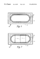
- FIG. 1 is a cross sectional view of a heat pipe fabricated according to the teachings of the present invention
- FIG. 2A is a perspective view of the wick of the present invention after formation of the capillary channels
- FIG. 2B is a cross sectional view of a portion of the wick fabricated according to the teachings of the present invention.
- FIG. 3 is a perspective view of the wick fabricated according to the teachings of the present invention being inserted into the heat pipe housing;
- FIG. 4 is a perspective view of the heat pipe fabricated according to the teachings of the present invention, showing the end caps attached to the housing;
- FIG. 5 is a cross sectional view of the wick fabricated according to the teachings of the present invention illustrating the desirable inverted meniscus heat transfer operation enabled by the present invention
- FIG. 6 is a cross sectional view of a prior art heat pipe.
- FIG. 7 is a cross sectional view of a heat pipe fabricated according to the teachings of the present invention illustrating the inclusion of stiffeners.
- micro channel heat pipe operates automatically and continuously by transferring heat from the heated, evaporator region to the cooler, condenser region, providing a self contained device for efficient heat transfer.
- FIG. 1 shows the micro channel heat pipe 10 in cross section.
- the heat pipe 10 includes a housing 12 .
- the housing 12 can be made from many different materials depending on application. For example, copper can be utilized due to its high heat transfer characteristics and ready commercial availability. Other representative choices of material include but are not considered limited to aluminum, stainless steel or nickel alloys, for example. Simply by way of example, and in order to illustrate the teachings and principles of the present invention, a 1 ⁇ 4 in. ⁇ 1 ⁇ 2 in. 0.048 in. wall tube is described. As can be appreciated, the size and configuration of tubing available to the skilled artisan is vast.
- a wick 14 is inserted into the housing 12 .
- the wick includes a plurality of micro capillary channels 16 .
- the wick 14 is fabricated from fine mesh wire cloth.
- the wire cloth is a 150 ⁇ 150 inch ⁇ 1 mesh copper screen cloth.
- Micro channel heat pipes are characterized as having at least one capillary channel such that r c /r h ⁇ 1 where r c is the capillary radius and r h is the hydraulic radius of the flow channel and capillary channels in the order of 0.2 mm or less are required for efficient micro channel heat pipe operation.
- the typical machining methods such as rolling, dicing saw cutting, electrodischarge machining, etc.
- the wick 14 of the present invention from wire cloth independently from the housing, the above described machining limitations have been dramatically overcome. More specifically, the desired micro capillary channels 16 can be readily formed in the wire cloth by known corrugation extrusion techniques such as described in U.S. Pat. No. 3,760,624, for example.
- the wick 14 after formation of the micro capillary channels 16 is illustrated in FIG. 2 A.
- the dimensions L C and L F as shown are dependent on the dimensions of the heat pipe housing, which vary according to application.
- the capillary channel depth ⁇ as shown in FIG. 2B is determined according to a predetermined aspect ratio of ⁇ /w. In the preferred embodiment, the aspect ratio is 4.5, with a capillary channel depth ⁇ of 0.9 mm, a width w of 0.2 mm, a wire cloth thickness t of 0.11 mm and the ratio r c /r h of 2.22.
- FIG. 3 illustrates a step in the process of fabrication of the micro channel heat pipe 10 of the present invention.
- the wick 14 is shown being inserted into the housing 12 .
- the wick 14 is retained within the housing 12 by a slight shrink fit.
- this shrink fit can be readily achieved by heating the housing 12 to an elevated temperature, such as 200° F. prior to the introduction of the wick 14 .
- the wick 14 is inserted at room temperature, and when the assembly cools to an equilibrium temperature, a net compressive force is exerted on the wick 14 . This assures a good mechanical fit, greatly enhancing thermal conduction, as well as simplifying fabrication. As shown in FIG.
- stiffeners 17 may be added, if desired, to force the wick 14 into contact with the housing 12 .
- the stiffeners 17 can be made porous by the addition of holes so as to allow free transference of vapor and fluid throughout the interior of the micro channel heat pipe 10 .
- the housing 12 is enclosed by the addition of end caps 18 incorporating fill tubes 20 .
- a suitable quantity of working fluid F is introduced into the micro channel heat pipe 10 using known vacuum transfer and fill procedures, via the fill tubes 20 .
- a quantity of working fluid F to saturate the wick structure is considered sufficient.
- the fill tubes 20 then can be pinched and sealed and excess length removed from the end caps 18 if desired.
- the working fluid F can be any number of suitable fluids, depending on temperature requirements. Representative fluids include but are not considered limited to water, alcohol, acetone, ammonia or refrigerant.
- the wire cloth wick 14 being permeable to the working fluid F, presents an equal number of closed and open channels for working fluid F flow as well as heat transference. This also has the desirable result of providing inverted-meniscus type evaporation during operation as shown in FIG. 5 . More specifically, the working fluid F vaporizes randomly in areas designated V. This in turn enables very high heat flux and has the further advantage of rendering the wick 14 dry-out tolerant. These advantages greatly enhance the efficiency of the micro channel heat pipe 10 of the present invention.
- the wick 14 facilitates capillary pumping action of the working fluid F, enhancing transport of the condensed fluid F from the condenser region (not shown) back to the heated, evaporator region (not shown), as well as facilitating working fluid F wicking in the circumferential direction.
- micro channel heat pipe 10 utilizes a fine mesh wire cloth wick 14 having micro capillary channels formed therein, providing enhanced heat transfer operation and presenting relative ease of fabrication.
Abstract
A micro channel heat pipe and method of fabrication are disclosed. The micro channel heat pipe includes a wire cloth wick having micro capillary channels formed by a corrugation extrusion process. The wick is inserted into the heat pipe housing in a shrink fit, enhancing heat transfer. The porous nature of the wire cloth wick permits free passage of the working fluid within both the closed and open micro capillary channels, doubling the number of micro capillary channels available for heat transference.
Description
The invention described herein may be manufactured and used by or for the Government of the United States for all governmental purposes without the payment of any royalty.
The present patent application document is somewhat related to the copending and commonly assigned patent application document “MICRO CHANNEL HEAT PIPE HAVING CORRUGATED FIN ELEMENTS AND METHOD OF FABRICATION”, AFD 00384, Ser. No. 09/389,270, filed on even date herewith. The contents of that even filing date application are hereby incorporated by reference herein.
The present invention relates generally to heat dissipating devices and more particularly to a micro channel heat pipe and method of fabrication.
As is well known in the art, heat pipes are closed, self contained devices that contain a volatile working fluid designed to transport thermal energy efficiently. In general, heat pipes have an inner cavity lined with a wick or grooves designed to provide a capillary structure for the transport of the working fluid.
In operation, the heat pipe takes advantage of the latent heat of vaporization of the working fluid. Heat is applied to one portion of the device, causing evaporation of the fluid in that portion of the chamber. The fluid vapor moves to a cooler portion of the device whereupon it condenses. The condensed fluid returns, and the action repeats itself.
As can be imagined, this vaporization and condensation action is continuous and provides for a very efficient means of transportation of thermal energy. The heat pipe is a sealed unit and requires no additional energy input to enable operation. Thus it is very efficient and is useful in a wide array of applications.
A current trend towards micro miniaturization of electronic components and high power devices gives rise to the desirability of correspondingly miniaturized cooling devices. As a result, attempts have been made to miniaturize heat pipes. However, as heat pipes are miniaturized, it becomes increasingly difficult to fabricate an effective wick structure to provide acceptable heat transfer operation. For example, forming of very narrow rectangular channels, 0.2 mm×0.9 mm or similar sizes and shapes within the internal walls of tubes with hydraulic diameter in the range of 5-10 mm is difficult. Appropriate groove cutting tools, extrusion dies and the like, necessary for cutting such small channels often provide unsatisfactory results and are expensive.
A need exists therefore for a micro channel heat pipe which provides high efficiency operation while simultaneously eliminating the difficulties encountered in fabrication heretofore encountered to date.
It is therefore a primary object of the present invention to provide a micro channel heat pipe and method of fabrication overcoming the limitations and disadvantages of the prior art techniques.
It is another object of the invention to provide a micro channel heat pipe that can be readily manufactured from known techniques.
It is still another object of the present invention to provide an improved micro channel heat pipe for efficient utilization in micro-miniature applications.
It is yet another object of the present invention to provide an improved micro channel heat pipe having a wire cloth wick for efficient heat transfer in micro-miniature applications.
These and other objects of the invention will become apparent as the description of the representative embodiments proceeds.
In accordance with the foregoing principles and objects of the invention, a micro channel heat pipe and method of fabrication are described. The method includes forming micro channels in a fine mesh wire cloth wick. The wick is inserted into the heat pipe housing and preferably includes a compression or shrink fit.
Micro channel heat pipes are characterized as having at least one capillary channel such that rc/rh≧1 where rc is the capillary radius and rh is the hydraulic radius of the flow channel. In order to provide efficient operation, the capillary channels in micro channel heat pipes are quite small, for example, 0.2 mm or less. The known groove forming methods such as rolling, dicing saw cutting, electrodischarge machining, etc. are difficult to enact properly, can provide unsatisfactory results and are expensive to perform.
As stated, the micro channel heat pipe of the present invention includes a wick formed from wire cloth. There are many benefits realized by utilizing wire cloth to form the wick of the present invention. By forming the wick from wire cloth, micro capillary channels can be easily formed therein by the ready application of known fin making processes. Since the wick thus formed is porous to the working fluid, the number of capillary channels available for heat transfer is doubled to incorporate both open and closed channels. As can be appreciated, this greatly enhances the operational efficiency of a micro channel heat pipe fabricated according to the teachings of the present invention. Moreover, the capillary action of the wick is greatly enhanced by the tight mesh of the wire cloth. Also, the wire cloth enables circumferential fluid distribution within the channels due to capillary action. This is not possible with the solid wall channels of the prior art.
Good mechanical contact between the wick and the heat pipe housing is assured by a shrink fit insertion process. More specifically, the housing is heated prior to insertion of the wick. When the housing cools and the assembly reaches an equilibrium temperature, a net compressive force will be exerted on the wick assuring good thermal contact, enhancing overall effectiveness.
By the avoidance of the complicated groove machining of the known techniques, another advantage of the present invention becomes apparent. More specifically, in order to machine the micro capillary channels within the housing, the housing correspondingly would have to be split longitudinally in order to provide access for machining purposes. However, by utilizing the teachings of the present invention, the housing need not be split because the wick is formed separately and then inserted into the housing. Advantageously, this contributes to low cost mass production.
The accompanying drawing incorporated in and forming a part of the specification, illustrates several aspects of the present invention and together with the description serves to explain the principles of the invention. In the drawing:
FIG. 1 is a cross sectional view of a heat pipe fabricated according to the teachings of the present invention;
FIG. 2A is a perspective view of the wick of the present invention after formation of the capillary channels;
FIG. 2B is a cross sectional view of a portion of the wick fabricated according to the teachings of the present invention;
FIG. 3 is a perspective view of the wick fabricated according to the teachings of the present invention being inserted into the heat pipe housing;
FIG. 4 is a perspective view of the heat pipe fabricated according to the teachings of the present invention, showing the end caps attached to the housing;
FIG. 5 is a cross sectional view of the wick fabricated according to the teachings of the present invention illustrating the desirable inverted meniscus heat transfer operation enabled by the present invention;
FIG. 6 is a cross sectional view of a prior art heat pipe; and,
FIG. 7 is a cross sectional view of a heat pipe fabricated according to the teachings of the present invention illustrating the inclusion of stiffeners.
Reference is made to the drawing figures showing the micro channel heat pipe of the present invention. The micro channel heat pipe operates automatically and continuously by transferring heat from the heated, evaporator region to the cooler, condenser region, providing a self contained device for efficient heat transfer.
FIG. 1 shows the micro channel heat pipe 10 in cross section. The heat pipe 10 includes a housing 12. The housing 12 can be made from many different materials depending on application. For example, copper can be utilized due to its high heat transfer characteristics and ready commercial availability. Other representative choices of material include but are not considered limited to aluminum, stainless steel or nickel alloys, for example. Simply by way of example, and in order to illustrate the teachings and principles of the present invention, a ¼ in.×½ in. 0.048 in. wall tube is described. As can be appreciated, the size and configuration of tubing available to the skilled artisan is vast.
As shown in FIG. 1, a wick 14 is inserted into the housing 12. The wick includes a plurality of micro capillary channels 16. According to an important aspect of the present invention, and as will be described in more detail below, the wick 14 is fabricated from fine mesh wire cloth. In the preferred embodiment the wire cloth is a 150×150 inch−1 mesh copper screen cloth.
As the trend towards micro miniaturization of electronic components continue, it becomes increasingly difficult to fabricate correspondingly sized micro channel heat pipes. The problem is further compounded by the fact that the heat flux requirements increase as component sizes decrease. As a result, very small dimensions become necessary for efficient capillary channel and corresponding heat pipe operation. Micro channel heat pipes are characterized as having at least one capillary channel such that rc/rh≧1 where rc is the capillary radius and rh is the hydraulic radius of the flow channel and capillary channels in the order of 0.2 mm or less are required for efficient micro channel heat pipe operation. The typical machining methods such as rolling, dicing saw cutting, electrodischarge machining, etc. are difficult to effect properly, can provide unsatisfactory results and are expensive to perform. Background material related to micro channel heat pipes which may be helpful in understanding the invention may be found by reference to “Micro/Miniature Heat Pipe Technology for Electronic Cooling”, by Faghri et al., WL-TR-97-2083, Wright Laboratory, Wright-Patterson AFB, Ohio (July 1997), and the references cited therein, the entire teachings of which are incorporated by reference herein.
Advantageously, by forming the wick 14 of the present invention from wire cloth independently from the housing, the above described machining limitations have been dramatically overcome. More specifically, the desired micro capillary channels 16 can be readily formed in the wire cloth by known corrugation extrusion techniques such as described in U.S. Pat. No. 3,760,624, for example.
The wick 14 after formation of the micro capillary channels 16, is illustrated in FIG. 2A. The dimensions LC and LF as shown are dependent on the dimensions of the heat pipe housing, which vary according to application. The capillary channel depth δ as shown in FIG. 2B, is determined according to a predetermined aspect ratio of δ/w. In the preferred embodiment, the aspect ratio is 4.5, with a capillary channel depth δ of 0.9 mm, a width w of 0.2 mm, a wire cloth thickness t of 0.11 mm and the ratio rc/rh of 2.22.
FIG. 3 illustrates a step in the process of fabrication of the micro channel heat pipe 10 of the present invention. The wick 14 is shown being inserted into the housing 12. Preferably, the wick 14 is retained within the housing 12 by a slight shrink fit. Advantageously, this shrink fit can be readily achieved by heating the housing 12 to an elevated temperature, such as 200° F. prior to the introduction of the wick 14. The wick 14 is inserted at room temperature, and when the assembly cools to an equilibrium temperature, a net compressive force is exerted on the wick 14. This assures a good mechanical fit, greatly enhancing thermal conduction, as well as simplifying fabrication. As shown in FIG. 7, one or more stiffeners 17 may be added, if desired, to force the wick 14 into contact with the housing 12. The stiffeners 17 can be made porous by the addition of holes so as to allow free transference of vapor and fluid throughout the interior of the micro channel heat pipe 10.
As shown in FIG. 4, the housing 12 is enclosed by the addition of end caps 18 incorporating fill tubes 20. After attachment of the end caps 18, a suitable quantity of working fluid F is introduced into the micro channel heat pipe 10 using known vacuum transfer and fill procedures, via the fill tubes 20. Generally, a quantity of working fluid F to saturate the wick structure is considered sufficient. The fill tubes 20 then can be pinched and sealed and excess length removed from the end caps 18 if desired. The working fluid F can be any number of suitable fluids, depending on temperature requirements. Representative fluids include but are not considered limited to water, alcohol, acetone, ammonia or refrigerant.
Since the wire cloth wick 14 contains micro pores, (0.085 mm in the preferred embodiment) the present invention advantageously provides for enhanced heat transfer effectiveness. This is because the micro pores work as a capillary pumping wick, providing a desirable capillary pumping action to compliment the flow of working fluid F within the channels 16 during operation. This composite wick arrangement provides enhanced performance characteristics such as better evaporator priming and increased evaporator heat flux, advantages not possible in the prior art machined groove design. The dramatic advantage of the present invention is clearly shown by comparison to the prior art device 100 illustrated in FIG. 6. As shown in this prior art device, only the open channels 102 are available for working fluid F flow. The ridges 104, obviously cannot transfer working fluid. But, according to the teachings of the present invention, the wire cloth wick 14, being permeable to the working fluid F, presents an equal number of closed and open channels for working fluid F flow as well as heat transference. This also has the desirable result of providing inverted-meniscus type evaporation during operation as shown in FIG. 5. More specifically, the working fluid F vaporizes randomly in areas designated V. This in turn enables very high heat flux and has the further advantage of rendering the wick 14 dry-out tolerant. These advantages greatly enhance the efficiency of the micro channel heat pipe 10 of the present invention. Moreover, it should also be appreciated that due to the porous nature of the wire cloth, the wick 14 facilitates capillary pumping action of the working fluid F, enhancing transport of the condensed fluid F from the condenser region (not shown) back to the heated, evaporator region (not shown), as well as facilitating working fluid F wicking in the circumferential direction.
In summary, numerous benefits have been described from utilizing the principles of the present invention. In particular, the micro channel heat pipe 10 utilizes a fine mesh wire cloth wick 14 having micro capillary channels formed therein, providing enhanced heat transfer operation and presenting relative ease of fabrication.
The foregoing description of the preferred embodiment has been presented for purposes of illustration and description. It is not intended to be exhaustive or to limit the invention to the precise form disclosed. Obvious modifications or variations are possible in light of the above teachings. The embodiment was chosen and described to provide the best illustration of the principles of the invention and its practical application to thereby enable one of ordinary skill in the art to utilize the inventions in various embodiments and with various modifications as are suited to the particular scope of the invention as determined by the appended claims when interpreted in accordance with the breadth to which they are fairly, legally and equitably entitled.
Claims (9)
1. A method of fabricating a micro channel heat pipe, comprising the steps of:
providing a housing having an inner cavity, said housing having a longitudinal axis;
forming, by corrugation extrusion, a one piece porous wire cloth wick to have a plurality of adjacent axial rectangular open and closed micro capillary channels formed therein, said micro capillary channels characterized by the relation rc/rh≧1, wherein rc is the capillary radius and rh is the hydraulic radius of said channels;
inserting said wick within said inner cavity such that said wick contacts at least a portion of the surface of said inner cavity, said wick extending continuously along said longitudinal axis of said housing;
attaching a pair of end caps to enclose said housing; and,
introducing a sufficient quantity of working fluid into said housing.
2. The method of claim 1 wherein said wick is inserted in a shrink fit manner.
3. The method of claim 2 wherein said inserting step is preceded by the step of heating said housing.
4. The method of claim 1 wherein said working fluid is selected from the group consisting of water, alcohol, acetone, ammonia and refrigerant.
5. The method of claim 1 wherein said housing comprises a material selected from the group of copper, aluminum, stainless steel and nickel alloy.
6. The method of claim 1 wherein said attaching step is preceded by the step of inserting a stiffener for forcing said wick into contact with said housing.
7. A micro channel heat pipe, comprising:
a housing having an inner cavity;
a porous wire cloth wick disposed within said housing, said wick having a plurality of adjacent axial rectangular open and closed micro capillary channels formed therein, said micro capillary channels characterized by the relation rc/rh≧1, wherein rc is the capillary radius and rh is the hydraulic radius of said channels, said wick contacting at least a portion of the surface of said inner cavity; and,
a sufficient quantity of working fluid within said housing, said working fluid saturating said wick and permeating across said open and closed micro capillary channels of said wick, whereby both of said open and said closed channels are presented for fluid flow and heat transference.
8. The heat pipe of claim 7 wherein said working fluid is selected from the group consisting of water, alcohol acetone, ammonia and refrigerant.
9. The heat pipe of claim 7 wherein said housing comprises a material selected from the group of copper, aluminum, stainless steel and nickel alloy.
Priority Applications (1)
| Application Number | Priority Date | Filing Date | Title |
|---|---|---|---|
| US09/389,269 US6293333B1 (en) | 1999-09-02 | 1999-09-02 | Micro channel heat pipe having wire cloth wick and method of fabrication |
Applications Claiming Priority (1)
| Application Number | Priority Date | Filing Date | Title |
|---|---|---|---|
| US09/389,269 US6293333B1 (en) | 1999-09-02 | 1999-09-02 | Micro channel heat pipe having wire cloth wick and method of fabrication |
Publications (1)
| Publication Number | Publication Date |
|---|---|
| US6293333B1 true US6293333B1 (en) | 2001-09-25 |
Family
ID=23537557
Family Applications (1)
| Application Number | Title | Priority Date | Filing Date |
|---|---|---|---|
| US09/389,269 Expired - Fee Related US6293333B1 (en) | 1999-09-02 | 1999-09-02 | Micro channel heat pipe having wire cloth wick and method of fabrication |
Country Status (1)
| Country | Link |
|---|---|
| US (1) | US6293333B1 (en) |
Cited By (72)
| Publication number | Priority date | Publication date | Assignee | Title |
|---|---|---|---|---|
| US20030042006A1 (en) * | 2001-08-28 | 2003-03-06 | Advanced Materials Technologies Pte. Ltd. | Advanced microelectronic heat dissipation package and method for its manufacture |
| US20030089486A1 (en) * | 1998-06-08 | 2003-05-15 | Thermotek, Inc. | Cooling apparatus having low profile extrusion and method of manufacture therefor |
| US20040069455A1 (en) * | 2002-08-28 | 2004-04-15 | Lindemuth James E. | Vapor chamber with sintered grooved wick |
| US6725910B2 (en) * | 1997-12-08 | 2004-04-27 | Diamond Electric Mfg. Co., Ltd. | Heat pipe and method for processing the same |
| US20040092988A1 (en) * | 2002-11-08 | 2004-05-13 | Shaolian Samuel M. | Transpedicular intervertebral disk access methods and devices |
| US20040099407A1 (en) * | 2002-11-26 | 2004-05-27 | Thermotek, Inc. | Stacked low profile cooling system and method for making same |
| US6782942B1 (en) * | 2003-05-01 | 2004-08-31 | Chin-Wen Wang | Tabular heat pipe structure having support bodies |
| US20040177946A1 (en) * | 2003-02-17 | 2004-09-16 | Fujikura Ltd. | Heat pipe excellent in reflux characteristic |
| US20040226546A1 (en) * | 2002-03-22 | 2004-11-18 | Pellizzari Roberto O. | Fuel injector for an internal combustion engine |
| US20040244951A1 (en) * | 1999-05-12 | 2004-12-09 | Dussinger Peter M. | Integrated circuit heat pipe heat spreader with through mounting holes |
| US20050006061A1 (en) * | 1998-06-08 | 2005-01-13 | Tony Quisenberry | Toroidal low-profile extrusion cooling system and method thereof |
| US20050011633A1 (en) * | 2003-07-14 | 2005-01-20 | Garner Scott D. | Tower heat sink with sintered grooved wick |
| US20050022975A1 (en) * | 2003-06-26 | 2005-02-03 | Rosenfeld John H. | Brazed wick for a heat transfer device and method of making same |
| US20050022976A1 (en) * | 2003-06-26 | 2005-02-03 | Rosenfeld John H. | Heat transfer device and method of making same |
| US6863117B2 (en) | 2002-02-26 | 2005-03-08 | Mikros Manufacturing, Inc. | Capillary evaporator |
| US6871792B2 (en) | 2002-03-22 | 2005-03-29 | Chrysalis Technologies Incorporated | Apparatus and method for preparing and delivering fuel |
| US6901994B1 (en) * | 2004-01-05 | 2005-06-07 | Industrial Technology Research Institute | Flat heat pipe provided with means to enhance heat transfer thereof |
| US20050150636A1 (en) * | 2004-01-08 | 2005-07-14 | Yang Hongwu | Heat pipe radiator for eliminating heat of electric component |
| US6945317B2 (en) | 2003-04-24 | 2005-09-20 | Thermal Corp. | Sintered grooved wick with particle web |
| US20050230085A1 (en) * | 2002-02-26 | 2005-10-20 | Mikros Manufacturing, Inc. | Capillary condenser/evaporator |
| US20050269064A1 (en) * | 2004-06-02 | 2005-12-08 | Hul-Chun Hsu | Planar heat pipe structure |
| US20050274495A1 (en) * | 2004-05-28 | 2005-12-15 | Wang Chin W | Cylindrical heat pipe structure |
| US20050274120A1 (en) * | 1999-06-08 | 2005-12-15 | Tony Quisenberry | Heat pipe connection system and method |
| US20050284615A1 (en) * | 2001-11-27 | 2005-12-29 | Parish Overton L | Geometrically reoriented low-profile phase plane heat pipes |
| US6981322B2 (en) | 1999-06-08 | 2006-01-03 | Thermotek, Inc. | Cooling apparatus having low profile extrusion and method of manufacture therefor |
| US20060090884A1 (en) * | 2004-11-02 | 2006-05-04 | Sang-Wook Park | Heat pipe and heat pipe structure |
| US20060124281A1 (en) * | 2003-06-26 | 2006-06-15 | Rosenfeld John H | Heat transfer device and method of making same |
| US20060169439A1 (en) * | 2005-01-28 | 2006-08-03 | Chu-Wan Hong | Heat pipe with wick structure of screen mesh |
| US20060213062A1 (en) * | 2005-03-28 | 2006-09-28 | Asia Vital Components Co., Ltd. | Method for making a heat dissipating device |
| US20070163749A1 (en) * | 2005-10-28 | 2007-07-19 | Hideyuki Miyahara | Component package having heat exchanger |
| US20070187074A1 (en) * | 2004-06-29 | 2007-08-16 | Industrial Technology Research Institute | Heat dissipating apparatus having micro-structure layer and method of fabricating the same |
| US20070211431A1 (en) * | 2004-06-04 | 2007-09-13 | Cooligy Inc. | Gimballed attachment for multiple heat exchangers |
| US20080013278A1 (en) * | 2006-06-30 | 2008-01-17 | Fredric Landry | Reservoir for liquid cooling systems used to provide make-up fluid and trap gas bubbles |
| US20080142196A1 (en) * | 2006-12-17 | 2008-06-19 | Jian-Dih Jeng | Heat Pipe with Advanced Capillary Structure |
| US20080210405A1 (en) * | 2002-11-01 | 2008-09-04 | Madhav Datta | Fabrication of high surface to volume ratio structures and their integration in microheat exchangers for liquid cooling systems |
| US20090025907A1 (en) * | 2003-10-15 | 2009-01-29 | Thermal Corp. | Fluid circuit heat transfer device for plural heat sources |
| US20090242175A1 (en) * | 2008-03-31 | 2009-10-01 | Lucent Technologies, Inc. | Thermal energy transfer device |
| US20090260793A1 (en) * | 2008-04-21 | 2009-10-22 | Wang Cheng-Tu | Long-acting heat pipe and corresponding manufacturing method |
| WO2009127015A2 (en) * | 2008-04-17 | 2009-10-22 | Edith Cowan University | Heat transfer fabric, system and method |
| US20100018678A1 (en) * | 2004-12-01 | 2010-01-28 | Convergence Technologies Limited | Vapor Chamber with Boiling-Enhanced Multi-Wick Structure |
| WO2010046182A2 (en) * | 2008-10-24 | 2010-04-29 | Siemens Aktiengesellschaft | Dynamoelectric machine |
| US7715194B2 (en) | 2006-04-11 | 2010-05-11 | Cooligy Inc. | Methodology of cooling multiple heat sources in a personal computer through the use of multiple fluid-based heat exchanging loops coupled via modular bus-type heat exchangers |
| US20100157537A1 (en) * | 2008-12-22 | 2010-06-24 | Fu Zhun Precision Industry (Shen Zhen) Co., Ltd. | Fin-type heat sink and electronic device using same |
| US7746634B2 (en) | 2007-08-07 | 2010-06-29 | Cooligy Inc. | Internal access mechanism for a server rack |
| US7806168B2 (en) | 2002-11-01 | 2010-10-05 | Cooligy Inc | Optimal spreader system, device and method for fluid cooled micro-scaled heat exchange |
| US7913719B2 (en) | 2006-01-30 | 2011-03-29 | Cooligy Inc. | Tape-wrapped multilayer tubing and methods for making the same |
| US20110108243A1 (en) * | 2009-11-12 | 2011-05-12 | Fu Zhun Precision Industry (Shen Zhen) Co., Ltd. | Plate-type heat pipe |
| DE202005021911U1 (en) | 2005-08-24 | 2011-05-12 | Ohb System Ag | heat pipe |
| US8157001B2 (en) | 2006-03-30 | 2012-04-17 | Cooligy Inc. | Integrated liquid to air conduction module |
| US8235096B1 (en) * | 2009-04-07 | 2012-08-07 | University Of Central Florida Research Foundation, Inc. | Hydrophilic particle enhanced phase change-based heat exchange |
| US8250877B2 (en) | 2008-03-10 | 2012-08-28 | Cooligy Inc. | Device and methodology for the removal of heat from an equipment rack by means of heat exchangers mounted to a door |
| US20130037244A1 (en) * | 2009-02-26 | 2013-02-14 | Sheng-Lin Wu | Flat heat pipe |
| US8434225B2 (en) | 2009-04-07 | 2013-05-07 | University Of Central Florida Research Foundation, Inc. | Hydrophilic particle enhanced heat exchange and method of manufacture |
| US8464781B2 (en) | 2002-11-01 | 2013-06-18 | Cooligy Inc. | Cooling systems incorporating heat exchangers and thermoelectric layers |
| US8602092B2 (en) | 2003-07-23 | 2013-12-10 | Cooligy, Inc. | Pump and fan control concepts in a cooling system |
| CN103712498A (en) * | 2013-12-19 | 2014-04-09 | 华中科技大学 | Double-capillary-core evaporator applied to flat-type LHP system |
| RU2526846C2 (en) * | 2012-06-09 | 2014-08-27 | Федеральное государственное автономное образовательное учреждение высшего профессионального образования "Уральский федеральный университет имени первого Президента России Б.Н. Ельцина" | Brushless electric machine |
| US9113577B2 (en) | 2001-11-27 | 2015-08-18 | Thermotek, Inc. | Method and system for automotive battery cooling |
| US20150292818A1 (en) * | 2012-08-18 | 2015-10-15 | Audi Ag | Heat exchanger |
| US9404392B2 (en) | 2012-12-21 | 2016-08-02 | Elwha Llc | Heat engine system |
| US20160290734A1 (en) * | 2015-03-30 | 2016-10-06 | Infinera Corporation | Low-cost nano-heat pipe |
| US9752832B2 (en) | 2012-12-21 | 2017-09-05 | Elwha Llc | Heat pipe |
| US20170318702A1 (en) * | 2016-04-29 | 2017-11-02 | Intel Corporation | Wickless capillary driven constrained vapor bubble heat pipes for application in electronic devices with various system platforms |
| EP1682309B1 (en) * | 2003-10-28 | 2018-12-19 | Orbital ATK, Inc. | Manufacture of an evaporator for a heat transfer system |
| US20190035713A1 (en) * | 2017-07-28 | 2019-01-31 | Qualcomm Incorporated | Systems and methods for cooling an electronic device |
| CN109341393A (en) * | 2018-10-22 | 2019-02-15 | 华南理工大学 | The separate type microchannel aluminothermy pipe pipe and its manufacturing method of a variety of capillary wicks |
| US10463077B2 (en) | 2016-06-24 | 2019-11-05 | Altria Client Services Llc | Cartridge for e-vaping device with open-microchannels |
| CN111707116A (en) * | 2020-04-30 | 2020-09-25 | 哈尔滨工业大学(深圳)(哈尔滨工业大学深圳科技创新研究院) | Microchannel heat exchanger with multistage microchannels and manufacturing method thereof |
| US20200386487A1 (en) * | 2017-12-01 | 2020-12-10 | Autonetworks Technologies, Ltd. | Heat transfer device and energy storage module |
| US11187469B2 (en) | 2018-12-20 | 2021-11-30 | General Electric Company | Tunable wicking structures and a system for a wicking structure |
| US20220099382A1 (en) * | 2019-01-29 | 2022-03-31 | Smarth Technology Ltd. | Boiling enhancement device |
| US20220196338A1 (en) * | 2020-12-23 | 2022-06-23 | Abb Schweiz Ag | Heat-transfer device and method to produce such a device |
Citations (23)
| Publication number | Priority date | Publication date | Assignee | Title |
|---|---|---|---|---|
| US3598180A (en) * | 1970-07-06 | 1971-08-10 | Robert David Moore Jr | Heat transfer surface structure |
| US3680189A (en) * | 1970-12-09 | 1972-08-01 | Noren Products Inc | Method of forming a heat pipe |
| US3720988A (en) | 1971-09-20 | 1973-03-20 | Mc Donnell Douglas Corp | Method of making a heat pipe |
| US3760624A (en) | 1972-05-08 | 1973-09-25 | J Robinson | Self feeding continuous forming device |
| US3789920A (en) * | 1970-05-21 | 1974-02-05 | Nasa | Heat transfer device |
| US4046190A (en) * | 1975-05-22 | 1977-09-06 | The United States Of America As Represented By The Administrator Of The National Aeronautics And Space Administration | Flat-plate heat pipe |
| US4047198A (en) * | 1976-04-19 | 1977-09-06 | Hughes Aircraft Company | Transistor cooling by heat pipes having a wick of dielectric powder |
| US4116266A (en) * | 1974-08-02 | 1978-09-26 | Agency Of Industrial Science & Technology | Apparatus for heat transfer |
| US4212347A (en) * | 1978-12-20 | 1980-07-15 | Thermacore, Inc. | Unfurlable heat pipe |
| US4240257A (en) * | 1973-02-22 | 1980-12-23 | The Singer Company | Heat pipe turbo generator |
| US4353415A (en) * | 1979-07-30 | 1982-10-12 | United Kingdom Atomic Energy Authority | Heat pipes and thermal siphons |
| US4394344A (en) * | 1981-04-29 | 1983-07-19 | Werner Richard W | Heat pipes for use in a magnetic field |
| US4846263A (en) * | 1984-12-27 | 1989-07-11 | Kabushiki Kaisha Toshiba | Heat pipe |
| US4883116A (en) * | 1989-01-31 | 1989-11-28 | The United States Of America As Represented By The Administrator Of The National Aeronautics And Space Administration | Ceramic heat pipe wick |
| US5029389A (en) * | 1987-12-14 | 1991-07-09 | Hughes Aircraft Company | Method of making a heat pipe with improved end cap |
| US5303768A (en) * | 1993-02-17 | 1994-04-19 | Grumman Aerospace Corporation | Capillary pump evaporator |
| US5309457A (en) * | 1992-12-22 | 1994-05-03 | Minch Richard B | Micro-heatpipe cooled laser diode array |
| US5520244A (en) * | 1992-12-16 | 1996-05-28 | Sdl, Inc. | Micropost waste heat removal system |
| US5642776A (en) * | 1996-02-27 | 1997-07-01 | Thermacore, Inc. | Electrically insulated envelope heat pipe |
| US5771967A (en) * | 1996-09-12 | 1998-06-30 | The United States Of America As Represented By The Secretary Of The Navy | Wick-interrupt temperature controlling heat pipe |
| US5785088A (en) | 1997-05-08 | 1998-07-28 | Wuh Choung Industrial Co., Ltd. | Fiber pore structure incorporate with a v-shaped micro-groove for use with heat pipes |
| US6070654A (en) * | 1998-04-03 | 2000-06-06 | Nissho Iwai Corporation | Heat pipe method for making the same and radiating structure |
| US6216343B1 (en) * | 1999-09-02 | 2001-04-17 | The United States Of America As Represented By The Secretary Of The Air Force | Method of making micro channel heat pipe having corrugated fin elements |
-
1999
- 1999-09-02 US US09/389,269 patent/US6293333B1/en not_active Expired - Fee Related
Patent Citations (23)
| Publication number | Priority date | Publication date | Assignee | Title |
|---|---|---|---|---|
| US3789920A (en) * | 1970-05-21 | 1974-02-05 | Nasa | Heat transfer device |
| US3598180A (en) * | 1970-07-06 | 1971-08-10 | Robert David Moore Jr | Heat transfer surface structure |
| US3680189A (en) * | 1970-12-09 | 1972-08-01 | Noren Products Inc | Method of forming a heat pipe |
| US3720988A (en) | 1971-09-20 | 1973-03-20 | Mc Donnell Douglas Corp | Method of making a heat pipe |
| US3760624A (en) | 1972-05-08 | 1973-09-25 | J Robinson | Self feeding continuous forming device |
| US4240257A (en) * | 1973-02-22 | 1980-12-23 | The Singer Company | Heat pipe turbo generator |
| US4116266A (en) * | 1974-08-02 | 1978-09-26 | Agency Of Industrial Science & Technology | Apparatus for heat transfer |
| US4046190A (en) * | 1975-05-22 | 1977-09-06 | The United States Of America As Represented By The Administrator Of The National Aeronautics And Space Administration | Flat-plate heat pipe |
| US4047198A (en) * | 1976-04-19 | 1977-09-06 | Hughes Aircraft Company | Transistor cooling by heat pipes having a wick of dielectric powder |
| US4212347A (en) * | 1978-12-20 | 1980-07-15 | Thermacore, Inc. | Unfurlable heat pipe |
| US4353415A (en) * | 1979-07-30 | 1982-10-12 | United Kingdom Atomic Energy Authority | Heat pipes and thermal siphons |
| US4394344A (en) * | 1981-04-29 | 1983-07-19 | Werner Richard W | Heat pipes for use in a magnetic field |
| US4846263A (en) * | 1984-12-27 | 1989-07-11 | Kabushiki Kaisha Toshiba | Heat pipe |
| US5029389A (en) * | 1987-12-14 | 1991-07-09 | Hughes Aircraft Company | Method of making a heat pipe with improved end cap |
| US4883116A (en) * | 1989-01-31 | 1989-11-28 | The United States Of America As Represented By The Administrator Of The National Aeronautics And Space Administration | Ceramic heat pipe wick |
| US5520244A (en) * | 1992-12-16 | 1996-05-28 | Sdl, Inc. | Micropost waste heat removal system |
| US5309457A (en) * | 1992-12-22 | 1994-05-03 | Minch Richard B | Micro-heatpipe cooled laser diode array |
| US5303768A (en) * | 1993-02-17 | 1994-04-19 | Grumman Aerospace Corporation | Capillary pump evaporator |
| US5642776A (en) * | 1996-02-27 | 1997-07-01 | Thermacore, Inc. | Electrically insulated envelope heat pipe |
| US5771967A (en) * | 1996-09-12 | 1998-06-30 | The United States Of America As Represented By The Secretary Of The Navy | Wick-interrupt temperature controlling heat pipe |
| US5785088A (en) | 1997-05-08 | 1998-07-28 | Wuh Choung Industrial Co., Ltd. | Fiber pore structure incorporate with a v-shaped micro-groove for use with heat pipes |
| US6070654A (en) * | 1998-04-03 | 2000-06-06 | Nissho Iwai Corporation | Heat pipe method for making the same and radiating structure |
| US6216343B1 (en) * | 1999-09-02 | 2001-04-17 | The United States Of America As Represented By The Secretary Of The Air Force | Method of making micro channel heat pipe having corrugated fin elements |
Cited By (141)
| Publication number | Priority date | Publication date | Assignee | Title |
|---|---|---|---|---|
| US6725910B2 (en) * | 1997-12-08 | 2004-04-27 | Diamond Electric Mfg. Co., Ltd. | Heat pipe and method for processing the same |
| US7322400B2 (en) | 1998-06-08 | 2008-01-29 | Thermotek, Inc. | Cooling apparatus having low profile extrusion |
| US8418478B2 (en) | 1998-06-08 | 2013-04-16 | Thermotek, Inc. | Cooling apparatus having low profile extrusion and method of manufacture therefor |
| US7147045B2 (en) | 1998-06-08 | 2006-12-12 | Thermotek, Inc. | Toroidal low-profile extrusion cooling system and method thereof |
| US20030089486A1 (en) * | 1998-06-08 | 2003-05-15 | Thermotek, Inc. | Cooling apparatus having low profile extrusion and method of manufacture therefor |
| US20030089487A1 (en) * | 1998-06-08 | 2003-05-15 | Thermotek, Inc. | Cooling apparatus having low profile extrusion and method of manufacture therefor |
| US6935409B1 (en) * | 1998-06-08 | 2005-08-30 | Thermotek, Inc. | Cooling apparatus having low profile extrusion |
| US6988315B2 (en) | 1998-06-08 | 2006-01-24 | Thermotek, Inc. | Cooling apparatus having low profile extrusion and method of manufacture therefor |
| US7802436B2 (en) | 1998-06-08 | 2010-09-28 | Thermotek, Inc. | Cooling apparatus having low profile extrusion and method of manufacture therefor |
| US7686069B2 (en) | 1998-06-08 | 2010-03-30 | Thermotek, Inc. | Cooling apparatus having low profile extrusion and method of manufacture therefor |
| US20050006061A1 (en) * | 1998-06-08 | 2005-01-13 | Tony Quisenberry | Toroidal low-profile extrusion cooling system and method thereof |
| US20040244951A1 (en) * | 1999-05-12 | 2004-12-09 | Dussinger Peter M. | Integrated circuit heat pipe heat spreader with through mounting holes |
| US7305843B2 (en) | 1999-06-08 | 2007-12-11 | Thermotek, Inc. | Heat pipe connection system and method |
| US20050274120A1 (en) * | 1999-06-08 | 2005-12-15 | Tony Quisenberry | Heat pipe connection system and method |
| US6981322B2 (en) | 1999-06-08 | 2006-01-03 | Thermotek, Inc. | Cooling apparatus having low profile extrusion and method of manufacture therefor |
| US20060000584A1 (en) * | 2001-08-28 | 2006-01-05 | Advanced Materials Technology Pte. Ltd. | Advanced microelectronic heat dissipation package and method for its manufacture |
| US6935022B2 (en) | 2001-08-28 | 2005-08-30 | Advanced Materials Technologies Pte, Ltd. | Advanced microelectronic heat dissipation package and method for its manufacture |
| US20030042006A1 (en) * | 2001-08-28 | 2003-03-06 | Advanced Materials Technologies Pte. Ltd. | Advanced microelectronic heat dissipation package and method for its manufacture |
| US20050284616A1 (en) * | 2001-08-28 | 2005-12-29 | Advanced Materials Technology Pte. Ltd. | Advanced microelectronic heat dissipation package and method for its manufacture |
| US20090277613A9 (en) * | 2001-11-27 | 2009-11-12 | Parish Overton L | Geometrically reoriented low-profile phase plane heat pipes |
| US8621875B2 (en) * | 2001-11-27 | 2014-01-07 | Thermotek, Inc. | Method of removing heat utilizing geometrically reoriented low-profile phase plane heat pipes |
| US20050039887A1 (en) * | 2001-11-27 | 2005-02-24 | Parish Overton L. | Stacked low profile cooling system and method for making same |
| US7150312B2 (en) | 2001-11-27 | 2006-12-19 | Thermotek, Inc. | Stacked low profile cooling system and method for making same |
| US20110209853A1 (en) * | 2001-11-27 | 2011-09-01 | Parish Overton L | Geometrically reoriented low-profile phase plane heat pipes |
| US9113577B2 (en) | 2001-11-27 | 2015-08-18 | Thermotek, Inc. | Method and system for automotive battery cooling |
| US7857037B2 (en) | 2001-11-27 | 2010-12-28 | Thermotek, Inc. | Geometrically reoriented low-profile phase plane heat pipes |
| US20050284615A1 (en) * | 2001-11-27 | 2005-12-29 | Parish Overton L | Geometrically reoriented low-profile phase plane heat pipes |
| US9877409B2 (en) | 2001-11-27 | 2018-01-23 | Thermotek, Inc. | Method for automotive battery cooling |
| US20050230085A1 (en) * | 2002-02-26 | 2005-10-20 | Mikros Manufacturing, Inc. | Capillary condenser/evaporator |
| US7775261B2 (en) | 2002-02-26 | 2010-08-17 | Mikros Manufacturing, Inc. | Capillary condenser/evaporator |
| US6863117B2 (en) | 2002-02-26 | 2005-03-08 | Mikros Manufacturing, Inc. | Capillary evaporator |
| US7059307B2 (en) | 2002-03-22 | 2006-06-13 | Philip Morris Usa Inc. | Fuel injector for an internal combustion engine |
| US6871792B2 (en) | 2002-03-22 | 2005-03-29 | Chrysalis Technologies Incorporated | Apparatus and method for preparing and delivering fuel |
| US20040226546A1 (en) * | 2002-03-22 | 2004-11-18 | Pellizzari Roberto O. | Fuel injector for an internal combustion engine |
| US20050100843A1 (en) * | 2002-03-22 | 2005-05-12 | Pellizzari Roberto O. | Apparatus and method for preparing and delivering fuel |
| US7225998B2 (en) | 2002-03-22 | 2007-06-05 | Philip Morris Usa Inc. | Apparatus and method for preparing and delivering fuel |
| US20040069455A1 (en) * | 2002-08-28 | 2004-04-15 | Lindemuth James E. | Vapor chamber with sintered grooved wick |
| US6880626B2 (en) * | 2002-08-28 | 2005-04-19 | Thermal Corp. | Vapor chamber with sintered grooved wick |
| US20050098303A1 (en) * | 2002-08-28 | 2005-05-12 | Lindemuth James E. | Vapor chamber with sintered grooved wick |
| US6997245B2 (en) | 2002-08-28 | 2006-02-14 | Thermal Corp. | Vapor chamber with sintered grooved wick |
| US8464781B2 (en) | 2002-11-01 | 2013-06-18 | Cooligy Inc. | Cooling systems incorporating heat exchangers and thermoelectric layers |
| US7806168B2 (en) | 2002-11-01 | 2010-10-05 | Cooligy Inc | Optimal spreader system, device and method for fluid cooled micro-scaled heat exchange |
| US20080210405A1 (en) * | 2002-11-01 | 2008-09-04 | Madhav Datta | Fabrication of high surface to volume ratio structures and their integration in microheat exchangers for liquid cooling systems |
| US7836597B2 (en) * | 2002-11-01 | 2010-11-23 | Cooligy Inc. | Method of fabricating high surface to volume ratio structures and their integration in microheat exchangers for liquid cooling system |
| US20040092988A1 (en) * | 2002-11-08 | 2004-05-13 | Shaolian Samuel M. | Transpedicular intervertebral disk access methods and devices |
| US20040099407A1 (en) * | 2002-11-26 | 2004-05-27 | Thermotek, Inc. | Stacked low profile cooling system and method for making same |
| US7198096B2 (en) | 2002-11-26 | 2007-04-03 | Thermotek, Inc. | Stacked low profile cooling system and method for making same |
| US7261142B2 (en) * | 2003-02-17 | 2007-08-28 | Fujikura, Ltd. | Heat pipe excellent in reflux characteristic |
| US20040177946A1 (en) * | 2003-02-17 | 2004-09-16 | Fujikura Ltd. | Heat pipe excellent in reflux characteristic |
| US7013958B2 (en) | 2003-04-24 | 2006-03-21 | Thermal Corp. | Sintered grooved wick with particle web |
| US6945317B2 (en) | 2003-04-24 | 2005-09-20 | Thermal Corp. | Sintered grooved wick with particle web |
| US20050236143A1 (en) * | 2003-04-24 | 2005-10-27 | Garner Scott D | Sintered grooved wick with particle web |
| US6782942B1 (en) * | 2003-05-01 | 2004-08-31 | Chin-Wen Wang | Tabular heat pipe structure having support bodies |
| US20060124281A1 (en) * | 2003-06-26 | 2006-06-15 | Rosenfeld John H | Heat transfer device and method of making same |
| US20050022984A1 (en) * | 2003-06-26 | 2005-02-03 | Rosenfeld John H. | Heat transfer device and method of making same |
| US7028759B2 (en) | 2003-06-26 | 2006-04-18 | Thermal Corp. | Heat transfer device and method of making same |
| US7124809B2 (en) | 2003-06-26 | 2006-10-24 | Thermal Corp. | Brazed wick for a heat transfer device |
| US6994152B2 (en) | 2003-06-26 | 2006-02-07 | Thermal Corp. | Brazed wick for a heat transfer device |
| US20050189091A1 (en) * | 2003-06-26 | 2005-09-01 | Rosenfeld John H. | Brazed wick for a heat transfer device and method of making same |
| US20050205243A1 (en) * | 2003-06-26 | 2005-09-22 | Rosenfeld John H | Brazed wick for a heat transfer device and method of making same |
| US20050022975A1 (en) * | 2003-06-26 | 2005-02-03 | Rosenfeld John H. | Brazed wick for a heat transfer device and method of making same |
| US20050022976A1 (en) * | 2003-06-26 | 2005-02-03 | Rosenfeld John H. | Heat transfer device and method of making same |
| US20050011633A1 (en) * | 2003-07-14 | 2005-01-20 | Garner Scott D. | Tower heat sink with sintered grooved wick |
| US6938680B2 (en) | 2003-07-14 | 2005-09-06 | Thermal Corp. | Tower heat sink with sintered grooved wick |
| US8602092B2 (en) | 2003-07-23 | 2013-12-10 | Cooligy, Inc. | Pump and fan control concepts in a cooling system |
| US20090025907A1 (en) * | 2003-10-15 | 2009-01-29 | Thermal Corp. | Fluid circuit heat transfer device for plural heat sources |
| US9273910B2 (en) * | 2003-10-15 | 2016-03-01 | Thermal Corp. | Fluid circuit heat transfer device for plural heat sources |
| EP1682309B1 (en) * | 2003-10-28 | 2018-12-19 | Orbital ATK, Inc. | Manufacture of an evaporator for a heat transfer system |
| US6901994B1 (en) * | 2004-01-05 | 2005-06-07 | Industrial Technology Research Institute | Flat heat pipe provided with means to enhance heat transfer thereof |
| US20050150636A1 (en) * | 2004-01-08 | 2005-07-14 | Yang Hongwu | Heat pipe radiator for eliminating heat of electric component |
| US20050274495A1 (en) * | 2004-05-28 | 2005-12-15 | Wang Chin W | Cylindrical heat pipe structure |
| US7275588B2 (en) * | 2004-06-02 | 2007-10-02 | Hul-Chun Hsu | Planar heat pipe structure |
| US20050269064A1 (en) * | 2004-06-02 | 2005-12-08 | Hul-Chun Hsu | Planar heat pipe structure |
| US20070211431A1 (en) * | 2004-06-04 | 2007-09-13 | Cooligy Inc. | Gimballed attachment for multiple heat exchangers |
| US7578338B2 (en) * | 2004-06-29 | 2009-08-25 | Industrial Technology Research Institute | Heat dissipating apparatus having micro-structure layer and method of fabricating the same |
| US20070187074A1 (en) * | 2004-06-29 | 2007-08-16 | Industrial Technology Research Institute | Heat dissipating apparatus having micro-structure layer and method of fabricating the same |
| US20060090884A1 (en) * | 2004-11-02 | 2006-05-04 | Sang-Wook Park | Heat pipe and heat pipe structure |
| US20100018678A1 (en) * | 2004-12-01 | 2010-01-28 | Convergence Technologies Limited | Vapor Chamber with Boiling-Enhanced Multi-Wick Structure |
| US20060169439A1 (en) * | 2005-01-28 | 2006-08-03 | Chu-Wan Hong | Heat pipe with wick structure of screen mesh |
| US20060213062A1 (en) * | 2005-03-28 | 2006-09-28 | Asia Vital Components Co., Ltd. | Method for making a heat dissipating device |
| US7461450B2 (en) * | 2005-03-28 | 2008-12-09 | Asia Vital Components Co., Ltd. | Method for making a heat dissipating device |
| DE202005021911U1 (en) | 2005-08-24 | 2011-05-12 | Ohb System Ag | heat pipe |
| US20070163749A1 (en) * | 2005-10-28 | 2007-07-19 | Hideyuki Miyahara | Component package having heat exchanger |
| US7900692B2 (en) * | 2005-10-28 | 2011-03-08 | Nakamura Seisakusho Kabushikigaisha | Component package having heat exchanger |
| US7913719B2 (en) | 2006-01-30 | 2011-03-29 | Cooligy Inc. | Tape-wrapped multilayer tubing and methods for making the same |
| US8157001B2 (en) | 2006-03-30 | 2012-04-17 | Cooligy Inc. | Integrated liquid to air conduction module |
| US7715194B2 (en) | 2006-04-11 | 2010-05-11 | Cooligy Inc. | Methodology of cooling multiple heat sources in a personal computer through the use of multiple fluid-based heat exchanging loops coupled via modular bus-type heat exchangers |
| US20080013278A1 (en) * | 2006-06-30 | 2008-01-17 | Fredric Landry | Reservoir for liquid cooling systems used to provide make-up fluid and trap gas bubbles |
| US20080142196A1 (en) * | 2006-12-17 | 2008-06-19 | Jian-Dih Jeng | Heat Pipe with Advanced Capillary Structure |
| US7746634B2 (en) | 2007-08-07 | 2010-06-29 | Cooligy Inc. | Internal access mechanism for a server rack |
| US8250877B2 (en) | 2008-03-10 | 2012-08-28 | Cooligy Inc. | Device and methodology for the removal of heat from an equipment rack by means of heat exchangers mounted to a door |
| US7832462B2 (en) * | 2008-03-31 | 2010-11-16 | Alcatel-Lucent Usa Inc. | Thermal energy transfer device |
| US20090242175A1 (en) * | 2008-03-31 | 2009-10-01 | Lucent Technologies, Inc. | Thermal energy transfer device |
| WO2009127015A2 (en) * | 2008-04-17 | 2009-10-22 | Edith Cowan University | Heat transfer fabric, system and method |
| WO2009127015A3 (en) * | 2008-04-17 | 2010-01-07 | Edith Cowan University | Heat transfer fabric, system and method |
| US20090260793A1 (en) * | 2008-04-21 | 2009-10-22 | Wang Cheng-Tu | Long-acting heat pipe and corresponding manufacturing method |
| US8919427B2 (en) * | 2008-04-21 | 2014-12-30 | Chaun-Choung Technology Corp. | Long-acting heat pipe and corresponding manufacturing method |
| CN102187549A (en) * | 2008-10-24 | 2011-09-14 | 西门子公司 | Dynamoelectric machine |
| US8350424B2 (en) | 2008-10-24 | 2013-01-08 | Siemens Aktiengesellschaft | Dynamoelectric machine |
| WO2010046182A3 (en) * | 2008-10-24 | 2010-07-29 | Siemens Aktiengesellschaft | Dynamoelectric machine |
| US20110227431A1 (en) * | 2008-10-24 | 2011-09-22 | Siemens Aktiengesellschaft | Dynamoelectric machine |
| RU2524170C2 (en) * | 2008-10-24 | 2014-07-27 | Сименс Акциенгезелльшафт | Dynamo-electric machine |
| WO2010046182A2 (en) * | 2008-10-24 | 2010-04-29 | Siemens Aktiengesellschaft | Dynamoelectric machine |
| CN102187549B (en) * | 2008-10-24 | 2014-09-17 | 西门子公司 | Dynamoelectric machine |
| US20100157537A1 (en) * | 2008-12-22 | 2010-06-24 | Fu Zhun Precision Industry (Shen Zhen) Co., Ltd. | Fin-type heat sink and electronic device using same |
| US7916485B2 (en) * | 2008-12-22 | 2011-03-29 | Fu Zhun Precision Industry (Shen Zhen) Co., Ltd. | Fin-type heat sink and electronic device using same |
| US20130037244A1 (en) * | 2009-02-26 | 2013-02-14 | Sheng-Lin Wu | Flat heat pipe |
| US8434225B2 (en) | 2009-04-07 | 2013-05-07 | University Of Central Florida Research Foundation, Inc. | Hydrophilic particle enhanced heat exchange and method of manufacture |
| US8235096B1 (en) * | 2009-04-07 | 2012-08-07 | University Of Central Florida Research Foundation, Inc. | Hydrophilic particle enhanced phase change-based heat exchange |
| US20110108243A1 (en) * | 2009-11-12 | 2011-05-12 | Fu Zhun Precision Industry (Shen Zhen) Co., Ltd. | Plate-type heat pipe |
| RU2526846C2 (en) * | 2012-06-09 | 2014-08-27 | Федеральное государственное автономное образовательное учреждение высшего профессионального образования "Уральский федеральный университет имени первого Президента России Б.Н. Ельцина" | Brushless electric machine |
| US20150292818A1 (en) * | 2012-08-18 | 2015-10-15 | Audi Ag | Heat exchanger |
| US9664459B2 (en) * | 2012-08-18 | 2017-05-30 | Audi Ag | Heat exchanger with a porous metal structure having manifolds and tubes |
| US9404392B2 (en) | 2012-12-21 | 2016-08-02 | Elwha Llc | Heat engine system |
| US9752832B2 (en) | 2012-12-21 | 2017-09-05 | Elwha Llc | Heat pipe |
| US10358945B2 (en) | 2012-12-21 | 2019-07-23 | Elwha Llc | Heat engine system |
| CN103712498B (en) * | 2013-12-19 | 2015-05-20 | 华中科技大学 | Double-capillary-core evaporator applied to flat-type LHP system |
| CN103712498A (en) * | 2013-12-19 | 2014-04-09 | 华中科技大学 | Double-capillary-core evaporator applied to flat-type LHP system |
| US20160290734A1 (en) * | 2015-03-30 | 2016-10-06 | Infinera Corporation | Low-cost nano-heat pipe |
| US10175005B2 (en) * | 2015-03-30 | 2019-01-08 | Infinera Corporation | Low-cost nano-heat pipe |
| US10962296B2 (en) | 2015-03-30 | 2021-03-30 | Infinera Corporation | Low-cost nano-heat pipe |
| US20170318702A1 (en) * | 2016-04-29 | 2017-11-02 | Intel Corporation | Wickless capillary driven constrained vapor bubble heat pipes for application in electronic devices with various system platforms |
| US11324139B2 (en) | 2016-04-29 | 2022-05-03 | Intel Corporation | Wickless capillary driven constrained vapor bubble heat pipes |
| US10694641B2 (en) * | 2016-04-29 | 2020-06-23 | Intel Corporation | Wickless capillary driven constrained vapor bubble heat pipes for application in electronic devices with various system platforms |
| US10917994B2 (en) | 2016-04-29 | 2021-02-09 | Intel Corporation | Wickless capillary driven constrained vapor bubble heat pipes for application in rack servers |
| US10463077B2 (en) | 2016-06-24 | 2019-11-05 | Altria Client Services Llc | Cartridge for e-vaping device with open-microchannels |
| US11951250B2 (en) | 2016-06-24 | 2024-04-09 | Altria Client Services Llc | Cartridge for e-vaping device with open-microchannels |
| US11471624B2 (en) | 2016-06-24 | 2022-10-18 | Altria Client Services Llc | Cartridge for e-vaping device with open-microchannels |
| US10622282B2 (en) * | 2017-07-28 | 2020-04-14 | Qualcomm Incorporated | Systems and methods for cooling an electronic device |
| US20190035713A1 (en) * | 2017-07-28 | 2019-01-31 | Qualcomm Incorporated | Systems and methods for cooling an electronic device |
| US11549759B2 (en) * | 2017-12-01 | 2023-01-10 | Autonetworks Technologies, Ltd. | Heat transfer device and energy storage module |
| US20200386487A1 (en) * | 2017-12-01 | 2020-12-10 | Autonetworks Technologies, Ltd. | Heat transfer device and energy storage module |
| CN109341393A (en) * | 2018-10-22 | 2019-02-15 | 华南理工大学 | The separate type microchannel aluminothermy pipe pipe and its manufacturing method of a variety of capillary wicks |
| CN109341393B (en) * | 2018-10-22 | 2023-11-21 | 华南理工大学 | Separated micro-channel aluminum heat pipe blank with multiple capillary liquid absorbing cores and manufacturing method thereof |
| US20220136781A1 (en) * | 2018-12-20 | 2022-05-05 | General Electric Company | Tunable wicking structures and a system for a wicking structure |
| US11187469B2 (en) | 2018-12-20 | 2021-11-30 | General Electric Company | Tunable wicking structures and a system for a wicking structure |
| US11698231B2 (en) * | 2018-12-20 | 2023-07-11 | General Electric Company | Tunable wicking structures and a system for a wicking structure |
| US20220099382A1 (en) * | 2019-01-29 | 2022-03-31 | Smarth Technology Ltd. | Boiling enhancement device |
| CN111707116A (en) * | 2020-04-30 | 2020-09-25 | 哈尔滨工业大学(深圳)(哈尔滨工业大学深圳科技创新研究院) | Microchannel heat exchanger with multistage microchannels and manufacturing method thereof |
| CN111707116B (en) * | 2020-04-30 | 2021-08-31 | 哈尔滨工业大学(深圳)(哈尔滨工业大学深圳科技创新研究院) | Microchannel heat exchanger with multistage microchannels and manufacturing method thereof |
| US20220196338A1 (en) * | 2020-12-23 | 2022-06-23 | Abb Schweiz Ag | Heat-transfer device and method to produce such a device |
Similar Documents
| Publication | Publication Date | Title |
|---|---|---|
| US6293333B1 (en) | Micro channel heat pipe having wire cloth wick and method of fabrication | |
| US6216343B1 (en) | Method of making micro channel heat pipe having corrugated fin elements | |
| US7013958B2 (en) | Sintered grooved wick with particle web | |
| US20120227935A1 (en) | Interconnected heat pipe assembly and method for manufacturing the same | |
| US6938680B2 (en) | Tower heat sink with sintered grooved wick | |
| US8622117B2 (en) | Heat pipe including a main wick structure and at least one auxiliary wick structure | |
| US7472479B2 (en) | Heat pipe and method of producing the same | |
| US20060207750A1 (en) | Heat pipe with composite capillary wick structure | |
| US5029389A (en) | Method of making a heat pipe with improved end cap | |
| CA2632725C (en) | Evaporator for use in a heat transfer system | |
| US7866374B2 (en) | Heat pipe with capillary wick | |
| US4674565A (en) | Heat pipe wick | |
| US20110174464A1 (en) | Flat heat pipe and method for manufacturing the same | |
| US20070240852A1 (en) | Heat pipe with heat reservoirs at both evaporating and condensing sections thereof | |
| US20070267179A1 (en) | Heat pipe with composite capillary wick and method of making the same | |
| US20100326644A1 (en) | Plane-type heat-dissipating structure with high heat-dissipating effect and method for manufacturing the same | |
| US20090166004A1 (en) | Heat pipe | |
| US20140060781A1 (en) | Heat pipe and method for manufactureing the same | |
| US6241008B1 (en) | Capillary evaporator | |
| KR20210033493A (en) | Heat pipe with variable transmittance wick structure | |
| US20140054014A1 (en) | Heat pipe and method for making the same | |
| US20220390185A1 (en) | Heat pipe with capillary structure | |
| US20130048248A1 (en) | Heat pipe manufacturing method and heat pipe thereof | |
| US20160153722A1 (en) | Heat pipe | |
| US20060113662A1 (en) | Micro heat pipe with wedge capillaries |
Legal Events
| Date | Code | Title | Description |
|---|---|---|---|
| AS | Assignment |
Owner name: AIR FORCE, UNITED STATES, OHIO Free format text: ASSIGNMENT OF ASSIGNORS INTEREST;ASSIGNORS:PONNAPPAN, RENGASAMY;LELAND, JOHN E.;REEL/FRAME:010303/0811 Effective date: 19990827 |
|
| FPAY | Fee payment |
Year of fee payment: 4 |
|
| REMI | Maintenance fee reminder mailed | ||
| LAPS | Lapse for failure to pay maintenance fees | ||
| STCH | Information on status: patent discontinuation |
Free format text: PATENT EXPIRED DUE TO NONPAYMENT OF MAINTENANCE FEES UNDER 37 CFR 1.362 |
|
| FP | Lapsed due to failure to pay maintenance fee |
Effective date: 20090925 |