US6292844B1 - Media storage device with embedded data filter for dynamically processing data during read and write operations - Google Patents

Media storage device with embedded data filter for dynamically processing data during read and write operations Download PDF

Info

Publication number
US6292844B1
US6292844B1 US09/022,926 US2292698A US6292844B1 US 6292844 B1 US6292844 B1 US 6292844B1 US 2292698 A US2292698 A US 2292698A US 6292844 B1 US6292844 B1 US 6292844B1
Authority
US
United States
Prior art keywords
data
storage device
media storage
register
stream
Prior art date
Legal status (The legal status is an assumption and is not a legal conclusion. Google has not performed a legal analysis and makes no representation as to the accuracy of the status listed.)
Expired - Lifetime
Application number
US09/022,926
Inventor
Scott Smyers
Bruce Fairman
Current Assignee (The listed assignees may be inaccurate. Google has not performed a legal analysis and makes no representation or warranty as to the accuracy of the list.)
Sony Corp
Sony Electronics Inc
Original Assignee
Sony Corp
Sony Electronics Inc
Priority date (The priority date is an assumption and is not a legal conclusion. Google has not performed a legal analysis and makes no representation as to the accuracy of the date listed.)
Filing date
Publication date
Application filed by Sony Corp, Sony Electronics Inc filed Critical Sony Corp
Assigned to SONY CORPORATION, SONY ELECTRONICS, INC. reassignment SONY CORPORATION ASSIGNMENT OF ASSIGNORS INTEREST (SEE DOCUMENT FOR DETAILS). Assignors: FAIRMAN, BRUCE, SMYERS, SCOTT
Priority to US09/022,926 priority Critical patent/US6292844B1/en
Priority to AT99906730T priority patent/ATE265085T1/en
Priority to PCT/US1999/002389 priority patent/WO1999041744A1/en
Priority to CA002320275A priority patent/CA2320275C/en
Priority to KR10-2000-7008300A priority patent/KR100475586B1/en
Priority to DE69916583T priority patent/DE69916583T2/en
Priority to EP99906730A priority patent/EP1055236B1/en
Priority to JP2000531845A priority patent/JP2003524848A/en
Priority to AU26570/99A priority patent/AU2657099A/en
Priority to HK01103595A priority patent/HK1033384A1/en
Publication of US6292844B1 publication Critical patent/US6292844B1/en
Application granted granted Critical
Anticipated expiration legal-status Critical
Expired - Lifetime legal-status Critical Current

Links

Images

Classifications

    • GPHYSICS
    • G11INFORMATION STORAGE
    • G11BINFORMATION STORAGE BASED ON RELATIVE MOVEMENT BETWEEN RECORD CARRIER AND TRANSDUCER
    • G11B20/00Signal processing not specific to the method of recording or reproducing; Circuits therefor
    • G11B20/10Digital recording or reproducing
    • G11B20/10009Improvement or modification of read or write signals
    • G11B20/10046Improvement or modification of read or write signals filtering or equalising, e.g. setting the tap weights of an FIR filter
    • HELECTRICITY
    • H04ELECTRIC COMMUNICATION TECHNIQUE
    • H04LTRANSMISSION OF DIGITAL INFORMATION, e.g. TELEGRAPHIC COMMUNICATION
    • H04L12/00Data switching networks
    • H04L12/28Data switching networks characterised by path configuration, e.g. LAN [Local Area Networks] or WAN [Wide Area Networks]
    • H04L12/40Bus networks
    • H04L12/40052High-speed IEEE 1394 serial bus
    • H04L12/40058Isochronous transmission
    • GPHYSICS
    • G11INFORMATION STORAGE
    • G11BINFORMATION STORAGE BASED ON RELATIVE MOVEMENT BETWEEN RECORD CARRIER AND TRANSDUCER
    • G11B20/00Signal processing not specific to the method of recording or reproducing; Circuits therefor
    • HELECTRICITY
    • H04ELECTRIC COMMUNICATION TECHNIQUE
    • H04LTRANSMISSION OF DIGITAL INFORMATION, e.g. TELEGRAPHIC COMMUNICATION
    • H04L12/00Data switching networks
    • H04L12/28Data switching networks characterised by path configuration, e.g. LAN [Local Area Networks] or WAN [Wide Area Networks]
    • H04L12/40Bus networks
    • H04L12/40052High-speed IEEE 1394 serial bus
    • H04L12/40065Bandwidth and channel allocation
    • HELECTRICITY
    • H04ELECTRIC COMMUNICATION TECHNIQUE
    • H04LTRANSMISSION OF DIGITAL INFORMATION, e.g. TELEGRAPHIC COMMUNICATION
    • H04L12/00Data switching networks
    • H04L12/28Data switching networks characterised by path configuration, e.g. LAN [Local Area Networks] or WAN [Wide Area Networks]
    • H04L12/40Bus networks
    • H04L12/40052High-speed IEEE 1394 serial bus
    • H04L12/40071Packet processing; Packet format
    • HELECTRICITY
    • H04ELECTRIC COMMUNICATION TECHNIQUE
    • H04LTRANSMISSION OF DIGITAL INFORMATION, e.g. TELEGRAPHIC COMMUNICATION
    • H04L12/00Data switching networks
    • H04L12/28Data switching networks characterised by path configuration, e.g. LAN [Local Area Networks] or WAN [Wide Area Networks]
    • H04L12/40Bus networks
    • H04L12/40052High-speed IEEE 1394 serial bus
    • H04L12/40117Interconnection of audio or video/imaging devices
    • HELECTRICITY
    • H04ELECTRIC COMMUNICATION TECHNIQUE
    • H04LTRANSMISSION OF DIGITAL INFORMATION, e.g. TELEGRAPHIC COMMUNICATION
    • H04L12/00Data switching networks
    • H04L12/28Data switching networks characterised by path configuration, e.g. LAN [Local Area Networks] or WAN [Wide Area Networks]
    • H04L12/40Bus networks
    • H04L12/40052High-speed IEEE 1394 serial bus
    • H04L12/40123Interconnection of computers and peripherals

Definitions

  • the present invention relates to the field of writing data to and reading data from a media storage device. More particularly, the present invention relates to the field of manipulating the data read from or written to a media storage device.
  • the IEEE 1394-1995 standard “1394 Standard For A High Performance Serial Bus,” is an international standard for implementing an inexpensive high-speed serial bus architecture which supports both asynchronous and isochronous format data transfers.
  • the IEEE 1394-1995 bus has a universal clock called the cycle timer. This clock is synchronized on all nodes. Isochronous data transfers are real-time transfers which take place based on the universal clock such that the time intervals between significant instances have the same duration at both the transmitting and receiving applications. Each packet of data transferred isochronously is transferred in its own time period. An example of an ideal application for the transfer of data isochronously would be from a video recorder to a television set.
  • the video recorder records images and sounds and saves the data in discrete chunks or packets.
  • the video recorder then transfers each packet, representing the image and sound recorded over a limited time period, during that time period, for display by the television set.
  • the IEEE 1394-1995 standard bus architecture provides multiple independent channels for isochronous data transfer between applications. A six bit channel number is broadcast with the data to ensure reception by the appropriate application. This allows multiple applications to simultaneously transmit isochronous data across the bus structure.
  • Asynchronous transfers are traditional reliable data transfer operations which take place as soon as arbitration is won and transfer a maximum amount of data from a source to a destination.
  • the IEEE 1394-1995 standard provides a high-speed serial bus for interconnecting digital devices thereby providing a universal I/O connection.
  • the IEEE 1394-1995 standard defines a digital interface for the applications thereby eliminating the need for an application to convert digital data to analog data before it is transmitted across the bus.
  • a receiving application will receive digital data from the bus, not analog data, and will therefore not be required to convert analog data to digital data.
  • the cable required by the IEEE 1394-1995 standard is very thin in size compared to other bulkier cables used to connect such devices in other connection schemes.
  • Devices can be added and removed from an IEEE 1394-1995 bus while the bus is operational. If a device is so added or removed the bus will then automatically reconfigure itself for transmitting data between the then existing nodes.
  • a node is considered a logical entity with a unique address on the bus structure. Each node provides in a standard address space, an identification ROM, a standardized set of control registers and in addition, its own address space.
  • the IEEE 1394-1995 standard defines a protocol as illustrated in FIG. 1 .
  • This protocol includes a serial bus management block 10 coupled to a transaction layer 12 , a link layer 14 and a physical layer 16 .
  • the physical layer 16 provides the electrical and mechanical connection between a device and the IEEE 1394-1995 cable.
  • the physical layer 16 also provides arbitration to ensure that all devices coupled to the IEEE 1394-1995 bus have arbitrated access to the bus as well as actual data transmission and reception.
  • the link layer 14 provides data packet delivery service for both asynchronous and isochronous data packet transport. This supports both asynchronous data transport, using an acknowledgement protocol, and isochronous data transport, providing an un-acknowledged real-time guaranteed bandwidth protocol for just-in-time data delivery.
  • the transaction layer 12 supports the commands necessary to complete asynchronous data transfers, including read, write and lock.
  • the serial bus management block 10 contains an isochronous resource manager for managing isochronous data transfers.
  • the serial bus management block 10 also provides overall configuration control of the serial bus in the form of optimizing arbitration timing, guarantee of adequate electrical power for all devices on the bus, assignment of the cycle master, assignment of isochronous channel and bandwidth resources and basic notification of errors.
  • FIG. 2 A hard disk drive including an IEEE 1394-1995 serial bus interface is illustrated in FIG. 2 .
  • the hard disk drive 20 includes the IEEE 1394-1995 serial bus interface circuit 22 for interfacing to an IEEE 1394-1995 serial bus network.
  • the interface circuit 22 is coupled to a buffer controller 24 .
  • the buffer controller 24 is coupled to a random access memory (RAM) 26 and to a read/write channel circuit 28 .
  • the read/write channel circuit 28 is coupled to the media 30 on which data is stored within the hard disk drive 20 .
  • the read/write channel circuit 28 controls the storage operations on the media 30 , including reading data from the media 30 and writing data to the media 30 .
  • a stream of data is received from a device coupled to the IEEE 1394-1995 serial bus structure by the IEEE 1394-1995 interface circuit 22 .
  • This stream of data is forwarded from the IEEE 1394-1995 interface circuit 22 to the buffer controller 24 .
  • the buffer controller 24 then stores this data temporarily in a buffer in the RAM 26 .
  • the buffer controller 24 reads the data from the RAM 26 and forwards it to the read/write channel circuit 28 .
  • the read/write channel circuit 28 then writes the data onto the media 30 .
  • a stream of data is read from the media 30 by the read/write channel circuit 28 .
  • This stream of data is forwarded by the read/write channel circuit 28 to the buffer controller 24 .
  • the buffer controller 24 then stores this data temporarily in a buffer in the RAM 26 .
  • the buffer controller 24 reads the data from the RAM 26 and forwards it to the interface circuit 22 .
  • the IEEE 1394-1995 serial bus interface circuit 22 then formats the data according to the requirements of the IEEE 1394-1995 standard and transmits this data to the appropriate device or devices over the IEEE 1394-1995 serial bus.
  • a traditional hard disk drive 20 records data and plays it back according to commands received from an external controller using a protocol such as the serial bus protocol (SBP).
  • SBP serial bus protocol
  • the external controller provides command data structures to the hard disk drive 20 which inform the hard disk drive 20 where on the media 30 the data is to be written, in the case of a write operation, or read from, in the case of a read operation.
  • the function of the hard disk drive 20 during a read operation is to recreate the original, unmodified stream of data which was previously written on the media 30 .
  • What is needed is a filtering device which can be used to manipulate the data from a consumer device into a format required by a personal computer or other device. What is further needed is a filtering device which can also manipulate the data from a personal computer device into a format required by a consumer electronic device.
  • a media storage device includes an embedded filter for manipulating universal clock based streams of data as they are written to or read from the media storage device.
  • the media storage device will also manipulate streams of data which are not being written to or read from the media storage device.
  • the embedded filter within the media storage device is an isochronous data pipe which will receive programmed instructions from an external controller and manipulate streams of data according to the programmed instructions in real time, coordinated with the universal clock.
  • the isochronous data pipe includes fixed firmware for performing the appropriate manipulations.
  • the media storage device is also preferably coupled to an IEEE 1394-1995 serial bus structure. As streams of data are received by the media storage device during a write operation, those streams of data can be manipulated into a different format by the embedded filter before they are stored on the media within the media storage device.
  • streams of data are being transmitted from the media storage device during a read operation, those streams of data can be manipulated into a different format by the embedded filter before they are transmitted onto the IEEE 1394-1995 serial bus structure.
  • the universal clock can be used to synchronize the data streams.
  • the media storage device will also utilize the embedded filter to manipulate streams of data being transmitted between two other devices on the IEEE 1394-1995 serial bus structure.
  • FIG. 1 illustrates a protocol stack defined by the IEEE 1394-1995 standard.
  • FIG. 2 illustrates a block diagram of a media storage device of the prior art.
  • FIG. 3 illustrates a block diagram of a media storage device according to the present invention.
  • FIG. 4 illustrates a register file within the isochronous data pipe.
  • FIG. 5 illustrates a register file within the isochronous data pipe sequencer.
  • a media storage device of the present invention includes an embedded data filter for filtering data as it is either written to the media storage device or read from the media storage device.
  • this embedded data filter is an isochronous data pipe which is programmable and will manipulate streams of data and the universal clock into the proper format.
  • the isochronous data pipe is preferably programmed for the appropriate manipulations by an external controller which is controlling the media storage device.
  • the isochronous data pipe includes fixed firmware for performing the appropriate manipulations.
  • the media storage device with the embedded filter of the present invention takes advantage of the central role of the media storage device in the communication of data between consumer electronic devices and a personal computer within an IEEE 1394-1995 serial bus network.
  • the embedded filter within the media storage device adds the ability to filter data inside the media storage device as it is being written to the media storage device or read from the media storage device.
  • the media storage device with embedded filter can also be used to filter a stream of data, even if the data is not being written to or read from the media storage device.
  • the embedded filter will manipulate a stream of data into a proper format for the device to which the data is directed, under the control of the external controlling device.
  • the embedded filter within the media storage device will manipulate those communications from the received format into a proper format for the personal computer.
  • the communications will then be in the proper format for the personal computer.
  • the personal computer will not have to perform any further manipulation of the communications in order to utilize them as necessary.
  • the communications can also be manipulated a second time by the embedded filter when they are read from the media storage device by the personal computer. In the same manner, communications from the personal computer to a consumer device can be manipulated into the proper format for the consumer device by the embedded filter.
  • the media storage device 44 includes an IEEE 1394-1995 serial bus interface circuit 32 for sending communications to and receiving communications from other devices coupled to the IEEE 1394-1995 serial bus network.
  • the interface circuit 32 is coupled to an embedded filter 42 .
  • the embedded filter 42 is an isochronous data pipe.
  • the embedded filter 42 is coupled to a buffer controller 34 .
  • the buffer controller 34 is also coupled to a RAM 36 and to a read/write channel circuit 38 .
  • the read/write channel circuit 38 is coupled to media 40 on which data is stored within the media storage device 44 .
  • the read/write channel circuit 38 controls the storage operations on the media 40 , including reading data from the media 40 and writing data to the media 40 .
  • An external controller 46 is coupled to the embedded filter 42 for controlling the manipulation of data streams and to the buffer controller 34 for controlling read and write operations to the media 40 .
  • the IEEE 1394-1995 serial bus interface circuit 32 receives a stream of data from the IEEE 1394-1995 serial bus. The interface circuit 32 then forwards this data to the embedded filter 42 .
  • the embedded filter 42 modifies the data, byte by byte, as specified by the programmed instructions from the external controller 46 , and forwards the modified data to the buffer controller 34 .
  • the buffer controller 34 then stores this modified data temporarily in a buffer in the RAM 36 .
  • the buffer controller 34 reads the data from the RAM 36 and forwards it to the read/write channel circuit 38 .
  • the read/write channel circuit 38 then writes the data onto the media 40 . Because the embedded filter 42 is programmable, the data can be manipulated during a write operation, during a read operation or during both write and read operations.
  • a stream of data is read from the media 40 by the read/write channel circuit 38 .
  • This stream of data is forwarded by the read/write channel circuit 38 to the buffer controller 34 .
  • the buffer controller 34 then stores this data temporarily in a circular buffer in the RAM 36 .
  • the buffer controller 34 reads the data from the RAM 36 and forwards it to the embedded filter 42 . If the embedded filter 42 is programmed to manipulate the data stream during a read operation, this manipulation is performed and the data is forwarded to the IEEE 1394-1995 serial bus interface circuit 32 .
  • the IEEE 1394-1995 serial bus interface circuit 32 then formats the data according to the requirements of the IEEE 1394-1995 standard and transmits this data to the appropriate device or devices over the IEEE 1394-1995 serial bus.
  • the embedded filter 42 within the media storage device 44 of the present invention can be used to manipulate a stream of data being written to or read from the media 40 .
  • the embedded filter 42 can also be used to manipulate a stream of data being transmitted between two devices on the IEEE 1394-1995 serial bus which is not being written to or read from the media 40 .
  • the stream of data is received by the interface circuit 32 and forwarded to the embedded filter 42 .
  • the embedded filter 42 then manipulates this data according to a preprogrammed function and forwards the data to the buffer controller 34 .
  • the buffer controller 34 then temporarily stores the data within a circular buffer within the RAM 36 .
  • the buffer controller 34 then reads this data from the RAM 36 and forwards it to the embedded filter 42 .
  • the embedded filter 42 is also programmed to manipulate the data stream before it is retransmitted, then this manipulation is performed and the data is forwarded to the IEEE 1394-1995 serial bus interface circuit 32 .
  • the interface circuit 32 then retransmits the manipulated data onto the IEEE 1394-1995 serial bus structure.
  • the embedded filter 42 is preferably programmed by the external controller 46 to manipulate streams of data received by or to be transmitted by the media storage device 44 .
  • the embedded filter 42 includes fixed firmware for performing the appropriate manipulations.
  • the embedded filter 42 can be programmed to manipulate streams of data on the way into the media storage device and on the way out of the media storage device.
  • streams of data being written to the media storage device from any device on the network can all be formatted into a first format when they are stored on the media 40 . Then when data is read from the media 40 for transmission to a particular device, that data can be manipulated by the embedded filter 42 into an appropriate format for the particular device.
  • the embedded filter 42 can be used in special cases to manipulate streams of data from a first device to a second device on the IEEE 1394-1995 serial bus structure.
  • the embedded filter 42 is preferably an isochronous data pipe.
  • a preferred embodiment of the isochronous data pipe 42 is taught in U.S. patent application Ser. No. 08/612,322, filed on Mar. 7, 1996 and entitled “ISOCHRONOUS DATA PIPE FOR MANAGING AND MANIPULATING A HIGH-SPEED STREAM OF ISOCHRONOUS DATA FLOWING BETWEEN AN APPLICATION AND A BUS STRUCTURE,” which is hereby incorporated by reference.
  • the isochronous data pipe 42 is programmable and will execute a series of instructions on a stream of data in order to perform manipulations on the data as required to place the data in the appropriate format.
  • the isochronous data pipe 42 can be programmed to manipulate both asynchronous and isochronous data.
  • the isochronous data pipe 42 For each quadlet of data transferred, the isochronous data pipe 42 executes a predetermined number of instructions to manipulate the data as necessary from the received format into the receiving format. When converting data, the isochronous data pipe 42 operates on each quadlet of data independently. The isochronous data pipe 42 performs a programmable number of instructions on each quadlet in order to manipulate the data, as necessary.
  • the isochronous data pipe 42 also includes an independent, dedicated register file 48 .
  • the isochronous data pipe 42 is controlled by an independent, dedicated register file, as illustrated in FIG. 4 .
  • This register file is programmed by the external controller 46 and used to manipulate the data flowing through the isochronous data pipe 42 , as necessary.
  • the register file 180 preferably includes 120 bytes of data, numbered hexadecimally 0 through 77. In FIG. 4, the register file 180 is illustrated in a table format with 30 horizontal rows, each including four bytes of data.
  • An offset column 182 is included in FIG. 4, to show the offset of the beginning byte in each row from the address of the beginning of the register file 180 .
  • a read/write column 184 is also included to show whether the fields in each row can be either read from and written to or read from only.
  • the cycle time field cycle_time is a twenty bit field within bytes 0 - 2 of the register file 180 .
  • the cycle time field can be read from and written to.
  • the control event field which will be discussed below, contains the cycle number value
  • the cycle time field holds the cycle time on which the channel mask field will be loaded from the pending channel mask field as described below.
  • the control field is a thirty-two bit field within bytes 4 - 7 of the register file 180 .
  • the control field can be read from and written to.
  • the control field includes an event field, an output enable field, a stop on error field, a transmit enable field and a go field.
  • the event field is a four bit field in bits 28 - 31 of the control register.
  • the value in the event field defines the bus event for the isochronous data pipe 42 to use as a trigger. When this bus event occurs, the isochronous data pipe 42 transfers the value stored in the pending channel mask register pending_ch_mask to the current channel mask register ch_mask.
  • the event field is encoded for the possible bus events as illustrated in Table I below.
  • the isochronous data pipe when a value equal to 0 is written to the event field by an external controller the isochronous data pipe will then immediately transfer the value in the channels pending register to the channel mask register.
  • the event field holds a value equal to 1, the isochronous data pipe transfers the value in the channels pending register to the channel mask register on the programmed cycle time, as described above.
  • the output enable field is a four bit field in bits 4 - 7 of the control field. When any of the bits in the output enable field are set to a logical high value, then the corresponding DMA channel will assure that the appropriate path is kept full.
  • the stop on error field is a one bit field in bit 3 of the control field.
  • the isochronous data pipe 42 will stop the current operation on the first error encountered by setting the value in the channel mask register to a logical low value.
  • Possible errors when sending data include a data underrun or a missing cycle start packet.
  • Possible errors when receiving data include a data overrun, a missing cycle start packet, a data CRC error, an error in packet format or a channel missing error.
  • the transmit enable field is a one bit field in bit 1 of the control field.
  • the transmit enable bit When the transmit enable bit is set to a logical high value, the isochronous data pipe 42 will begin executing the output control store program.
  • the go bit When the go bit is at a logical low value or the output control store program executes a return instruction, the transmit enable bit will be cleared.
  • the go field is a one bit field in bit 0 of the control field.
  • the application sets the go bit to a logical high value to enable the isochronous data pipe to watch for an event.
  • the isochronous data pipe 42 transfers the contents of the pending channel mask register to the current channel mask register.
  • the status field is a thirty-two bit field within bytes 8 -B of the register file 180 .
  • the status field can be read from and written to.
  • the status field contains status information which reports the current state of the isochronous data pipe 42 .
  • the bits 0 - 7 of the status field correspond to the bits 0 - 7 of the control field and include an output field, a stop on error field, a transmit enable field and an active field.
  • the value of these fields in the status register indicate the current operational state of the isochronous data pipe 42 .
  • the bits 8 - 27 of the status field are reserved.
  • the active field is a one bit field in bit 0 of the status field, which indicates whether or not the isochronous data pipe is active.
  • the isochronous data pipe is currently active and transferring data. If the active bit is equal to a logical low value, the isochronous data pipe is not currently active.
  • the error field is a four bit field in bits 28 - 31 of the status field. When the isochronous data pipe 42 halts operation due to an error, the error field contains a value indicating the error condition. The error field is only valid when the active bit is equal to a logical low value. The possible values for the error field and the errors to which they correspond are listed in Table II below.
  • the pending channel mask high field pending_ch_mask_hi is a four byte field within bytes 20 - 23 of the register file 180 .
  • the pending channel mask low field pending_ch_mask_lo is a four byte field within bytes 24 - 27 of the register file 180 .
  • the two pending channel mask fields pending_ch_mask_hi and pending_ch_mask_lo form an eight byte field containing the mask of isochronous channel numbers for the isochronous data pipe 42 to receive.
  • the isochronous data pipe 42 transfers the contents of this field to the channel mask register when the programmed trigger event occurs.
  • the bit assignment of the pending channel mask field is the same as the bit assignment of the channels available register defined in chapter eight of the IEEE 1394-1995 standard.
  • the current channel mask high field ch_mask_hi is a four byte field within bytes 28 - 2 B of the register file 180 .
  • the current channel mask low field ch_mask_lo is a four byte field within bytes 2 C- 2 F of the register file 180 .
  • the two current channel mask fields ch_mask_hi and ch_mask_lo form an eight byte field containing the channel mask currently in operation, with each bit within the current channel mask fields representing an isochronous channel.
  • the channel mask field is only loaded from the pending channel mask field when a trigger event occurs.
  • the isochronous data pipe 42 ignores received isochronous channel numbers for which the corresponding bit in the current channel mask field is set to a logical low value.
  • the control store output field CS_output is a one byte field within byte 34 of the register file 180 .
  • the control store output field CS_output contains the control store address within the control store memory, to which the isochronous data pipe 42 dispatches when transmitting is enabled.
  • the control store memory contains instructions used by the isochronous data pipe in performing its operations on a stream of data.
  • the control store cycle start address field CS_addr_CS is a one byte field within byte 37 of the register file 180 .
  • the control store address field CS_addr_CS contains the control store address to which the isochronous data pipe branches when the cycle start packet is received.
  • the first quadlet available to the control store program is the first quadlet of the cycle start packet.
  • the control store address fields CS_addr — 0 through CS_addr — 63 are each one byte fields within bytes 38 through 77 of the register file 180 . These fields contain the control store address store where the isochronous data pipe is to branch upon receiving data on the isochronous channel matching the byte number of the control store address field.
  • control store address field CS_addr — 10 contains the address in the control store where the isochronous data pipe is to branch upon receiving data on the isochronous channel number 10.
  • the isochronous data pipe ignores all isochronous channels for which the corresponding value in the control store address field is equal to FFh.
  • the isochronous data pipe executes from that control store address until it encounters a return instruction.
  • the isochronous data pipe either returns to the idle state if transmitting was not previously enabled, or it returns to the location in the transmit control store program where it was prior to the dispatch.
  • the control store address fields CS_addr — 0 through CS_addr — 63 each correspond to an isochronous channel and contain the address in the control store memory where the instructions for that isochronous channel begin. Accordingly, when the isochronous data pipe 42 receives data on a particular isochronous channel, the isochronous data pipe 42 branches to the address contained in the corresponding control store address field to obtain the instructions for manipulating the data for that channel. Isochronous channels for which the corresponding value in the control store address field is equal to FFh are ignored, as are channels corresponding to bits in the current channel mask register which are equal to zero.
  • a stream of isochronous data is made up of one or more isochronous channels.
  • the isochronous data pipe 42 receives isochronous channels for which the corresponding bit in the current channel mask field is set to a logical high value.
  • the isochronous data pipe 42 transmits isochronous data according to the control store program beginning at the control store address pointed to by the value in the control store output CS_output register.
  • the isochronous data pipe 42 is actually a programmable sequencer which can be programmed to perform operations on the received stream of data.
  • the isochronous data pipe sequencer contains a register file as illustrated in FIG. 5 .
  • the immediate value register IMM is a thirty-four bit register with a register code of “0” which can only be a source register.
  • the immediate value register IMM specifies that the thirty-four bit immediate field of the instruction contains the source data for the given operation.
  • the bus input register BUS_IN is a thirty-two bit register with a register code of “1” which can only be a source register. Accessing the bus input register BUS_IN as a source of an operation clocks one quadlet of data through the isochronous data pipe 42 . Subsequent accesses to the bus input register BUS_IN access subsequent quadlets of data in the input data stream.
  • the bus output register BUS_OUT is a thirty-four bit register with a register code of “2” which can only be a destination register. Accessing the bus output register BUS_OUT as a destination of an operation clocks one quadlet of data through the isochronous data pipe 42 . Subsequent accesses to the bus output register BUS_OUT clock subsequent quadlets of data in the output data stream.
  • the data registers D0-D7 are each thirty-four bit registers with a register code of “4”, “5”, “6”, “7”, “8”, “9”, “A” and “B”, respectively, which can be either a source or destination register.
  • the data registers D0-D7 can be used as the source or destination register for any operation.
  • the data interface registers DATA — 0-DATA — 3 are each thirty-two bit registers with a register code of “10”, “11”, “12” and “13”, respectively, which can be either a source or destination register. Each of the data interface registers DATA — 0-DATA — 3 access a different DMA channel. Use of these registers is to be consistent with the programming of the output enable field DMA_out_en.
  • the isochronous data pipe 42 implements a stack made up of a linear list of eight one byte registers.
  • the stack registers are only accessed during a branch to subroutine instruction and a return instruction.
  • the stack registers S0-S7 each have a respective register address 0-7.
  • the actual number of stack registers will vary depending on the specific implementation.
  • the isochronous data pipe 42 When the isochronous data pipe 42 branches to a subroutine, the isochronous data pipe 42 stores the address of the next control store instruction into the current stack register, increments the value of the stack pointer, then branches to the control store instruction contained in the low order byte of the source field. When the isochronous data pipe 42 executes a return instruction, it decrements the stack pointer, then branches to the control store instruction contained in the current stack register. If the stack pointer is decremented when it contains a value equal to zero, the value of the stack pointer will remain at zero and the isochronous data pipe 42 will halt operation until it receives an isochronous data packet or cycle start packet.
  • the isochronous data pipe 42 When the isochronous data pipe is executing an output control store program and a cycle start packet or enabled isochronous channel is received, the isochronous data pipe 42 will interrupt execution of the output control store program, save the address of the current instruction in the stack, decrement the stack pointer and then dispatch to the proper location to handle the received packet.
  • Each isochronous control store instruction includes an OpCode field, a source field, a destination field, an immediate value field, an immediate field and a reserved field.
  • the OpCode field is a six bit field which describes an operation to perform.
  • the source field src is a four bit field which specifies a register or immediate value which contains the source value for the specified operation.
  • the destination field dest is a four bit field which specifies a destination register for the specified operation.
  • the immediate value field imm_val is a one bit field which when set to a logical high value, specifies that one of the operands is contained in the immediate field.
  • the immediate field imm is a thirty-four bit field which specifies an immediate value to use for an operation if the immediate value field imm_val is set to a logical high value.
  • the reserved field includes thirteen bits which are reserved for use in alternate embodiments of the isochronous data pipe 20 .
  • the operation codes which are implemented by the preferred embodiment of the isochronous data pipe sequencer during manipulation of a data stream and can be included in the OpCode field are listed in Table III below.
  • the isochronous data pipe 42 will store the results for any of these operations into any register which is capable of being a destination, as illustrated in FIG. 5, including the data registers D0-D7 and any DMA channel which is configured as a destination.
  • the mnemonic instruction which includes an “I” specifies the operation is to be conducted using the immediate value.
  • the mnemonic instruction which does not include an “I” specifies the operation is to be conducted between the values in the source and destination registers.
  • the value in the register specified in the source field src is moved to the register specified in the destination field dest. If the register specified in the source field src is a thirty-four bit register and the register specified in the destination field dest is a thirty-two bit register, the high order two bits will be lost. If the register specified in the source field src is a thirty-two bit register and the register specified in the destination field dest is a thirty-four bit register, then the high order two bits will both be set to a logical low value.
  • the register specified in the source field src is one of the data interface registers DATA — 0-DATA — 3, which access a DMA channel, or the bus input register BUS_IN.
  • the register specified in the destination field dest is one of the data interface registers DATA — 0-DATA — 3, which access a DMA channel, or the bus output register BUS_OUT.
  • a logical AND operation is performed on the values in the source field src and the destination field dest and the result is stored in the register specified in the destination field dest.
  • the ANDI form of this instruction uses the value in the immediate field instead of the value in the destination field as one of the operands and stores the result in the register specified in the destination field dest. If the register specified in the source field src is a thirty-four bit register and the register specified in the destination field dest is a thirty-two bit register, the high order two bits will be lost.
  • the register specified in the source field src is a thirty-two bit register and the register specified in the destination field dest is a thirty-four bit register, then the high order two bits will both be set to a logical low value. If both the registers specified in the source field src and the register specified in the destination field dest are thirty-four bit registers, then the AND operation is performed on all thirty-four bits.
  • a logical OR operation is performed on the values in the registers specified by the source field src and the destination field dest and the result is stored in the register specified in the destination field dest.
  • the ORI form of this instruction uses the value in the immediate field instead of the value in the destination field as one of the operands and stores the result in the register specified in the destination field dest. If the register specified in the source field src is a thirty-four bit register and the register specified in the destination field dest is a thirty-two bit register, the high order two bits will be lost.
  • the register specified in the source field src is a thirty-two bit register and the register specified in the destination field dest is a thirty-four bit register, then the high order two bits will both be set to a logical low value. If both the register specified in the source field src and the register specified in the destination field dest are thirty-four bit registers, then the OR operation is performed on all thirty-four bits.
  • the value in the destination register dest is shifted by the number of bits specified by the value in the source register src and the result is stored in the register specified in the destination field dest.
  • a positive shift value shifts the value in the destination register to the right towards the least significant bit and zeros are used to fill in the shifted bits on the left beginning with the most significant bit.
  • a negative shift value shifts the value in the destination register to the left towards the most significant bit and zeros are used to fill in the shifted bits on the right beginning with the least significant bit.
  • the SHIFTI form of this instruction shifts the value in the source register by the number of bits specified in the immediate field and stores the result in the register specified in the destination field.
  • the register specified in the source field src is a thirty-four bit register and the register specified in the destination field dest is a thirty-two bit register, the high order two bits will be lost. If the register specified in the source field src is a thirty-two bit register and the register specified in the destination field dest is a thirty-four bit register, then the high order two bits will both be set to a logical low value. If both the register specified in the source field src and the register specified in the destination field dest are thirty-four bit registers, then the shift operation is performed on only the low order thirty-two bits.
  • the value in the source register src is subtracted from the value in the destination register dest. If the result of the CMP operation is equal to zero, the Z bit is set to a logical high value. If the result of the CMP operation is not equal to zero, the Z bit is set to a logical low value.
  • the results of the CMP operation are not stored anywhere.
  • the CMPI form of this instruction subtracts the immediate value from the value in the source register src, and sets the Z bit as specified above, according to the result. This instruction also does not store the result of the operation.
  • the value in the source register src is added to the value in the destination register dest and the result is stored in the destination register dest.
  • the ADDI form of this instruction adds the value in the source register src to the immediate value and stores the result in the destination register dest. If the register specified in the source field src is a thirty-four bit register and the register specified in the destination field dest is a thirty-two bit register, the high order two bits will be lost. If the register specified in the source field src is a thirty-two bit register and the register specified in the destination field dest is a thirty-four bit register, then the high order two bits will both be set to a logical low value. If both the register specified in the source field src and the register specified in the destination field dest are thirty-four bit registers, then the ADD operation is performed on only the low order thirty-two bits.
  • the value in the destination register dest is subtracted from the value in the source register src and the result is stored in the destination register dest.
  • the SUBI form of this instruction subtracts the immediate value from the value in the source register and the result is stored in the destination register dest. If the register specified in the source field src is a thirty-four bit register and the register specified in the destination field dest is a thirty-two bit register, the high order two bits will be lost. If the register specified in the source field src is a thirty-two bit register and the register specified in the destination field dest is a thirty-four bit register, then the high order two bits will both be set to a logical low value. If both the register specified in the source field src and the register specified in the destination field dest are thirty-four bit registers, then the SUB operation is performed on only the low order thirty-two bits.
  • the value in the source register src is multiplied by the value in the destination register dest and the result is stored in the destination register dest.
  • the MULTI form of this instruction multiplies the immediate value by the value in the source register src and the result is stored in the destination register dest. If the register specified in the source field src is a thirty-four bit register and the register specified in the destination field dest is a thirty-two bit register, the high order two bits will be lost. If the register specified in the source field src is a thirty-two bit register and the register specified in the destination field dest is a thirty-four bit register, then the high order two bits will both be set to a logical low value. If both the register specified in the source field src and the register specified in the destination field dest are thirty-four bit registers, then the MULT operation is performed on only the low order thirty-two bits.
  • the isochronous data pipe 42 branches to the control store address contained in the low order byte of the source field src.
  • the source field src can specify a register or an immediate value.
  • the isochronous data pipe 42 branches to the control store address contained in the low order byte of the source field src if the result of the last arithmetic or move control store instruction was equal to zero.
  • the source field src can specify a register or an immediate value.
  • the isochronous data pipe 42 branches to the control store address contained in the low order byte of the source field src if the result of the last arithmetic or move control store instruction was not equal to zero.
  • the source field can specify a register or an immediate value.
  • the address of the next control store instruction is pushed onto the stack and the isochronous data pipe 42 branches to the control store address contained in the low order byte of the source field src.
  • the source field src can specify a register or an immediate value.
  • the source field src can specify a register or an immediate value.
  • the source field src can specify a register or an immediate value.
  • the last control store address is popped off of the stack and the isochronous data pipe 42 branches to that address.
  • the isochronous data pipe 42 of the preferred embodiment is programmed by a device before it can transfer and manipulate data. Once programmed and initialized, the control register is used to change the operational state of the isochronous data pipe 42 .
  • the current operational state is completely defined by the value in the current channel mask register and the information contained in the low order byte of the status register.
  • a new channel mask value is programmed into the pending channel mask register and a new operational state into the control register.
  • the go bit is also set and an event is programmed into the event field.
  • the isochronous data pipe 42 transfers the value in the pending channel mask register to the current channel mask register.
  • the isochronous data pipe 42 also transfers the information in the low order byte of the control register into the low order byte of the status register.
  • a value of all zeros is programmed into the pending channel mask register and a logical low value into the transmit enable bit in the control register.
  • the go bit is also set and an event is programmed into the event field of the control register.
  • the event occurs the value in the current channel mask register becomes zero and the transmit enable bit in the status register is pulled to a logical low value, thereby stopping the operation of the isochronous data pipe 42 .
  • the active bit in the status register is also pulled to a logical low value.
  • a control store program is loaded and the proper control store offsets are programmed into the control store address register file.
  • the pending channel mask register is then programmed with a bit mask of the channels which the isochronous data pipe 42 is to receive. If the isochronous data pipe 42 is not receiving data, the value in the pending channel mask register is programmed to zero.
  • the go bit in the control register is set to a logical high value to indicate a state change.
  • the transmit enable bit in the control register is set to a logical high value if the isochronous data pipe 42 is to transmit isochronous data.
  • the stop on error bit in the control register is set to a logical high value if the isochronous data pipe 42 is to stop operation on any error. If the isochronous data pipe 42 is transmitting isochronous data, the output enable bits in the control register which correspond to the DMA channels involved in transmitting isochronous data are set to a logical high value.
  • the event field in the control register is programmed to an event on which the isochronous data pipe 42 is to change state.
  • the isochronous data pipe 42 includes hard-coded, fixed firmware for manipulating data packets.
  • the isochronous data pipe will only manipulate communications into particular preprogrammed formats.
  • the isochronous data pipe within the preferred embodiment of the present invention can be programmed by the external controller 46 and configured for manipulating data packets into any desired format.
  • the appropriate conversion code is downloaded from the external controller 46 to the isochronous data pipe 42 .
  • the external controller 46 is preferably coupled directly to the media storage device 44 , it should also be apparent that the external controller 46 can alternatively be coupled to the media storage device 44 through the IEEE 1394-1995 serial bus network.
  • the embedded filter 42 is included within the media storage device 44 in order to take advantage of the fact that most streams of data will be written to and read from the media storage device 44 . Accordingly, the data being written to and read from the media storage device 44 can be manipulated by the embedded filter 42 without disrupting its flow. Data which is not being written to or read from the media storage device can also be manipulated by the embedded filter 42 as it is being transmitted from one device to another device on the IEEE 1394-1995 serial bus structure. During data operations involving the media storage device 44 , the data can be manipulated as it is being written to the media 40 or after it has been read from the media 40 and before it is transmitted on the IEEE 1394-1995 serial bus. The data can also be manipulated both as it is being written to and read from the media 40 .

Abstract

A media storage device includes an embedded filter for manipulating universal clock based streams of data as they are written to or read from the media storage device. The media storage device will also manipulate streams of data which are not being written to or read from the media storage device. Preferably the embedded filter within the media storage device is an isochronous data pipe which will receive programmed instructions from an external controller and manipulate streams of data according to the programmed instructions in real time, coordinated with the universal clock. Alternatively, the isochronous data pipe includes fixed firmware for performing the appropriate manipulations. The media storage device is also preferably coupled to an IEEE 1394-1995 serial bus structure. As streams of data are received by the media storage device during a write operation, those streams of data can be manipulated into a different format by the embedded filter before they are stored on the media within the media storage device. As streams of data are being transmitted from the media storage device during a read operation, those streams of data can be manipulated into a different format by the embedded filter before they are transmitted onto the IEEE 1394-1995 serial bus structure. In both instances, the universal clock can be used to synchronize the data streams. The media storage device will also utilize the embedded filter to manipulate streams of data being transmitted between two other devices on the IEEE 1394-1995 serial bus structure.

Description

FIELD OF THE INVENTION
The present invention relates to the field of writing data to and reading data from a media storage device. More particularly, the present invention relates to the field of manipulating the data read from or written to a media storage device.
BACKGROUND OF THE INVENTION
The IEEE 1394-1995 standard, “1394 Standard For A High Performance Serial Bus,” is an international standard for implementing an inexpensive high-speed serial bus architecture which supports both asynchronous and isochronous format data transfers. In addition, the IEEE 1394-1995 bus has a universal clock called the cycle timer. This clock is synchronized on all nodes. Isochronous data transfers are real-time transfers which take place based on the universal clock such that the time intervals between significant instances have the same duration at both the transmitting and receiving applications. Each packet of data transferred isochronously is transferred in its own time period. An example of an ideal application for the transfer of data isochronously would be from a video recorder to a television set. The video recorder records images and sounds and saves the data in discrete chunks or packets. The video recorder then transfers each packet, representing the image and sound recorded over a limited time period, during that time period, for display by the television set. The IEEE 1394-1995 standard bus architecture provides multiple independent channels for isochronous data transfer between applications. A six bit channel number is broadcast with the data to ensure reception by the appropriate application. This allows multiple applications to simultaneously transmit isochronous data across the bus structure. Asynchronous transfers are traditional reliable data transfer operations which take place as soon as arbitration is won and transfer a maximum amount of data from a source to a destination.
The IEEE 1394-1995 standard provides a high-speed serial bus for interconnecting digital devices thereby providing a universal I/O connection. The IEEE 1394-1995 standard defines a digital interface for the applications thereby eliminating the need for an application to convert digital data to analog data before it is transmitted across the bus. Correspondingly, a receiving application will receive digital data from the bus, not analog data, and will therefore not be required to convert analog data to digital data. The cable required by the IEEE 1394-1995 standard is very thin in size compared to other bulkier cables used to connect such devices in other connection schemes. Devices can be added and removed from an IEEE 1394-1995 bus while the bus is operational. If a device is so added or removed the bus will then automatically reconfigure itself for transmitting data between the then existing nodes. A node is considered a logical entity with a unique address on the bus structure. Each node provides in a standard address space, an identification ROM, a standardized set of control registers and in addition, its own address space.
The IEEE 1394-1995 standard defines a protocol as illustrated in FIG. 1. This protocol includes a serial bus management block 10 coupled to a transaction layer 12, a link layer 14 and a physical layer 16. The physical layer 16 provides the electrical and mechanical connection between a device and the IEEE 1394-1995 cable. The physical layer 16 also provides arbitration to ensure that all devices coupled to the IEEE 1394-1995 bus have arbitrated access to the bus as well as actual data transmission and reception. The link layer 14 provides data packet delivery service for both asynchronous and isochronous data packet transport. This supports both asynchronous data transport, using an acknowledgement protocol, and isochronous data transport, providing an un-acknowledged real-time guaranteed bandwidth protocol for just-in-time data delivery. The transaction layer 12 supports the commands necessary to complete asynchronous data transfers, including read, write and lock. The serial bus management block 10 contains an isochronous resource manager for managing isochronous data transfers. The serial bus management block 10 also provides overall configuration control of the serial bus in the form of optimizing arbitration timing, guarantee of adequate electrical power for all devices on the bus, assignment of the cycle master, assignment of isochronous channel and bandwidth resources and basic notification of errors.
A hard disk drive including an IEEE 1394-1995 serial bus interface is illustrated in FIG. 2. The hard disk drive 20 includes the IEEE 1394-1995 serial bus interface circuit 22 for interfacing to an IEEE 1394-1995 serial bus network. The interface circuit 22 is coupled to a buffer controller 24. The buffer controller 24 is coupled to a random access memory (RAM) 26 and to a read/write channel circuit 28. The read/write channel circuit 28 is coupled to the media 30 on which data is stored within the hard disk drive 20. The read/write channel circuit 28 controls the storage operations on the media 30, including reading data from the media 30 and writing data to the media 30.
During a write operation to the hard disk drive 20, a stream of data is received from a device coupled to the IEEE 1394-1995 serial bus structure by the IEEE 1394-1995 interface circuit 22. This stream of data is forwarded from the IEEE 1394-1995 interface circuit 22 to the buffer controller 24. The buffer controller 24 then stores this data temporarily in a buffer in the RAM 26. When the read/write channel circuit 28 is available, the buffer controller 24 reads the data from the RAM 26 and forwards it to the read/write channel circuit 28. The read/write channel circuit 28 then writes the data onto the media 30.
During a read operation from the hard disk drive 20, a stream of data is read from the media 30 by the read/write channel circuit 28. This stream of data is forwarded by the read/write channel circuit 28 to the buffer controller 24. The buffer controller 24 then stores this data temporarily in a buffer in the RAM 26. When the IEEE 1394-1995 serial bus interface circuit 22 is available, the buffer controller 24 reads the data from the RAM 26 and forwards it to the interface circuit 22. The IEEE 1394-1995 serial bus interface circuit 22 then formats the data according to the requirements of the IEEE 1394-1995 standard and transmits this data to the appropriate device or devices over the IEEE 1394-1995 serial bus.
A traditional hard disk drive 20, as described, records data and plays it back according to commands received from an external controller using a protocol such as the serial bus protocol (SBP). The external controller provides command data structures to the hard disk drive 20 which inform the hard disk drive 20 where on the media 30 the data is to be written, in the case of a write operation, or read from, in the case of a read operation. The function of the hard disk drive 20 during a read operation is to recreate the original, unmodified stream of data which was previously written on the media 30.
With the growing use of the IEEE 1394-1995 serial bus, personal computers are now being coupled together in IEEE 1394-1995 networks with devices which have not traditionally been coupled to personal computers. Examples of such devices are consumer electronic devices such as video cassette recorders, video camcorders, digital video disk players and compact disk players. Raw data from these consumer devices is not always directly usable by a personal computer. The typical solution to this problem is to write an application software program which will run on the personal computer and perform the necessary data manipulation to transform the data into a format which is useful to other applications being run by the personal computer.
What is needed is a filtering device which can be used to manipulate the data from a consumer device into a format required by a personal computer or other device. What is further needed is a filtering device which can also manipulate the data from a personal computer device into a format required by a consumer electronic device.
SUMMARY OF THE INVENTION
A media storage device includes an embedded filter for manipulating universal clock based streams of data as they are written to or read from the media storage device. The media storage device will also manipulate streams of data which are not being written to or read from the media storage device. Preferably the embedded filter within the media storage device is an isochronous data pipe which will receive programmed instructions from an external controller and manipulate streams of data according to the programmed instructions in real time, coordinated with the universal clock. Alternatively, the isochronous data pipe includes fixed firmware for performing the appropriate manipulations. The media storage device is also preferably coupled to an IEEE 1394-1995 serial bus structure. As streams of data are received by the media storage device during a write operation, those streams of data can be manipulated into a different format by the embedded filter before they are stored on the media within the media storage device. As streams of data are being transmitted from the media storage device during a read operation, those streams of data can be manipulated into a different format by the embedded filter before they are transmitted onto the IEEE 1394-1995 serial bus structure. In both instances, the universal clock can be used to synchronize the data streams. The media storage device will also utilize the embedded filter to manipulate streams of data being transmitted between two other devices on the IEEE 1394-1995 serial bus structure.
BRIEF DESCRIPTION OF THE DRAWINGS
FIG. 1 illustrates a protocol stack defined by the IEEE 1394-1995 standard.
FIG. 2 illustrates a block diagram of a media storage device of the prior art.
FIG. 3 illustrates a block diagram of a media storage device according to the present invention.
FIG. 4 illustrates a register file within the isochronous data pipe.
FIG. 5 illustrates a register file within the isochronous data pipe sequencer.
DETAILED DESCRIPTION OF THE PREFERRED EMBODIMENT
A media storage device of the present invention includes an embedded data filter for filtering data as it is either written to the media storage device or read from the media storage device. Preferably, this embedded data filter is an isochronous data pipe which is programmable and will manipulate streams of data and the universal clock into the proper format. The isochronous data pipe is preferably programmed for the appropriate manipulations by an external controller which is controlling the media storage device. Alternatively, the isochronous data pipe includes fixed firmware for performing the appropriate manipulations.
The media storage device with the embedded filter of the present invention takes advantage of the central role of the media storage device in the communication of data between consumer electronic devices and a personal computer within an IEEE 1394-1995 serial bus network. The embedded filter within the media storage device adds the ability to filter data inside the media storage device as it is being written to the media storage device or read from the media storage device. The media storage device with embedded filter can also be used to filter a stream of data, even if the data is not being written to or read from the media storage device.
Within the media storage device, the embedded filter will manipulate a stream of data into a proper format for the device to which the data is directed, under the control of the external controlling device. As an example, when storing communications from a consumer device which are to be used by a personal computer, the embedded filter within the media storage device will manipulate those communications from the received format into a proper format for the personal computer. When the communications are read by the personal computer from the media storage device, the communications will then be in the proper format for the personal computer. The personal computer will not have to perform any further manipulation of the communications in order to utilize them as necessary. If necessary, the communications can also be manipulated a second time by the embedded filter when they are read from the media storage device by the personal computer. In the same manner, communications from the personal computer to a consumer device can be manipulated into the proper format for the consumer device by the embedded filter.
A media storage device according to the present invention is illustrated in FIG. 3. The media storage device 44 includes an IEEE 1394-1995 serial bus interface circuit 32 for sending communications to and receiving communications from other devices coupled to the IEEE 1394-1995 serial bus network. The interface circuit 32 is coupled to an embedded filter 42. Preferably, the embedded filter 42 is an isochronous data pipe. The embedded filter 42 is coupled to a buffer controller 34. The buffer controller 34 is also coupled to a RAM 36 and to a read/write channel circuit 38. The read/write channel circuit 38 is coupled to media 40 on which data is stored within the media storage device 44. The read/write channel circuit 38 controls the storage operations on the media 40, including reading data from the media 40 and writing data to the media 40. An external controller 46 is coupled to the embedded filter 42 for controlling the manipulation of data streams and to the buffer controller 34 for controlling read and write operations to the media 40.
During a write operation to the media storage device 44, the IEEE 1394-1995 serial bus interface circuit 32 receives a stream of data from the IEEE 1394-1995 serial bus. The interface circuit 32 then forwards this data to the embedded filter 42. The embedded filter 42 modifies the data, byte by byte, as specified by the programmed instructions from the external controller 46, and forwards the modified data to the buffer controller 34. The buffer controller 34 then stores this modified data temporarily in a buffer in the RAM 36. When the read/write channel circuit 38 is available, the buffer controller 34 reads the data from the RAM 36 and forwards it to the read/write channel circuit 38. The read/write channel circuit 38 then writes the data onto the media 40. Because the embedded filter 42 is programmable, the data can be manipulated during a write operation, during a read operation or during both write and read operations.
During a read operation from the media storage device 44, a stream of data is read from the media 40 by the read/write channel circuit 38. This stream of data is forwarded by the read/write channel circuit 38 to the buffer controller 34. The buffer controller 34 then stores this data temporarily in a circular buffer in the RAM 36. When the IEEE 1394-1995 serial bus interface circuit 32 is available, the buffer controller 34 reads the data from the RAM 36 and forwards it to the embedded filter 42. If the embedded filter 42 is programmed to manipulate the data stream during a read operation, this manipulation is performed and the data is forwarded to the IEEE 1394-1995 serial bus interface circuit 32. The IEEE 1394-1995 serial bus interface circuit 32 then formats the data according to the requirements of the IEEE 1394-1995 standard and transmits this data to the appropriate device or devices over the IEEE 1394-1995 serial bus.
The embedded filter 42 within the media storage device 44 of the present invention can be used to manipulate a stream of data being written to or read from the media 40. The embedded filter 42 can also be used to manipulate a stream of data being transmitted between two devices on the IEEE 1394-1995 serial bus which is not being written to or read from the media 40. During such an operation, the stream of data is received by the interface circuit 32 and forwarded to the embedded filter 42. The embedded filter 42 then manipulates this data according to a preprogrammed function and forwards the data to the buffer controller 34. The buffer controller 34 then temporarily stores the data within a circular buffer within the RAM 36. The buffer controller 34 then reads this data from the RAM 36 and forwards it to the embedded filter 42. If the embedded filter 42 is also programmed to manipulate the data stream before it is retransmitted, then this manipulation is performed and the data is forwarded to the IEEE 1394-1995 serial bus interface circuit 32. The interface circuit 32 then retransmits the manipulated data onto the IEEE 1394-1995 serial bus structure.
The embedded filter 42 is preferably programmed by the external controller 46 to manipulate streams of data received by or to be transmitted by the media storage device 44. Alternatively, the embedded filter 42 includes fixed firmware for performing the appropriate manipulations. The embedded filter 42 can be programmed to manipulate streams of data on the way into the media storage device and on the way out of the media storage device. As an example of the utilization of the embedded filter 42 within an IEEE 1394-1995 serial bus network, streams of data being written to the media storage device from any device on the network can all be formatted into a first format when they are stored on the media 40. Then when data is read from the media 40 for transmission to a particular device, that data can be manipulated by the embedded filter 42 into an appropriate format for the particular device. Additionally, the embedded filter 42 can be used in special cases to manipulate streams of data from a first device to a second device on the IEEE 1394-1995 serial bus structure.
As described above, the embedded filter 42 is preferably an isochronous data pipe. A preferred embodiment of the isochronous data pipe 42 is taught in U.S. patent application Ser. No. 08/612,322, filed on Mar. 7, 1996 and entitled “ISOCHRONOUS DATA PIPE FOR MANAGING AND MANIPULATING A HIGH-SPEED STREAM OF ISOCHRONOUS DATA FLOWING BETWEEN AN APPLICATION AND A BUS STRUCTURE,” which is hereby incorporated by reference. The isochronous data pipe 42 is programmable and will execute a series of instructions on a stream of data in order to perform manipulations on the data as required to place the data in the appropriate format. The isochronous data pipe 42 can be programmed to manipulate both asynchronous and isochronous data.
For each quadlet of data transferred, the isochronous data pipe 42 executes a predetermined number of instructions to manipulate the data as necessary from the received format into the receiving format. When converting data, the isochronous data pipe 42 operates on each quadlet of data independently. The isochronous data pipe 42 performs a programmable number of instructions on each quadlet in order to manipulate the data, as necessary. The isochronous data pipe 42 also includes an independent, dedicated register file 48.
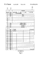
The isochronous data pipe 42 is controlled by an independent, dedicated register file, as illustrated in FIG. 4. This register file is programmed by the external controller 46 and used to manipulate the data flowing through the isochronous data pipe 42, as necessary. The register file 180 preferably includes 120 bytes of data, numbered hexadecimally 0 through 77. In FIG. 4, the register file 180 is illustrated in a table format with 30 horizontal rows, each including four bytes of data. An offset column 182 is included in FIG. 4, to show the offset of the beginning byte in each row from the address of the beginning of the register file 180. A read/write column 184 is also included to show whether the fields in each row can be either read from and written to or read from only.
The cycle time field cycle_time is a twenty bit field within bytes 0-2 of the register file 180. The cycle time field can be read from and written to. When the control event field, which will be discussed below, contains the cycle number value, the cycle time field holds the cycle time on which the channel mask field will be loaded from the pending channel mask field as described below.
The control field is a thirty-two bit field within bytes 4-7 of the register file 180. The control field can be read from and written to. The control field includes an event field, an output enable field, a stop on error field, a transmit enable field and a go field. The event field is a four bit field in bits 28-31 of the control register. The value in the event field defines the bus event for the isochronous data pipe 42 to use as a trigger. When this bus event occurs, the isochronous data pipe 42 transfers the value stored in the pending channel mask register pending_ch_mask to the current channel mask register ch_mask. The event field is encoded for the possible bus events as illustrated in Table I below.
TABLE I
value meaning
0 immediately
1 cycle number
2 reserved
3 reserved
4-F reserved
Therefore, when a value equal to 0 is written to the event field by an external controller the isochronous data pipe will then immediately transfer the value in the channels pending register to the channel mask register. When the event field holds a value equal to 1, the isochronous data pipe transfers the value in the channels pending register to the channel mask register on the programmed cycle time, as described above.
The output enable field is a four bit field in bits 4-7 of the control field. When any of the bits in the output enable field are set to a logical high value, then the corresponding DMA channel will assure that the appropriate path is kept full.
The stop on error field is a one bit field in bit 3 of the control field. When the stop on error bit is set to a logical high value, the isochronous data pipe 42 will stop the current operation on the first error encountered by setting the value in the channel mask register to a logical low value. Possible errors when sending data include a data underrun or a missing cycle start packet. Possible errors when receiving data include a data overrun, a missing cycle start packet, a data CRC error, an error in packet format or a channel missing error.
The transmit enable field is a one bit field in bit 1 of the control field. When the transmit enable bit is set to a logical high value, the isochronous data pipe 42 will begin executing the output control store program. When the go bit is at a logical low value or the output control store program executes a return instruction, the transmit enable bit will be cleared.
The go field is a one bit field in bit 0 of the control field. The application sets the go bit to a logical high value to enable the isochronous data pipe to watch for an event. When the specified event condition is satisfied, the isochronous data pipe 42 transfers the contents of the pending channel mask register to the current channel mask register.
The status field is a thirty-two bit field within bytes 8-B of the register file 180. The status field can be read from and written to. The status field contains status information which reports the current state of the isochronous data pipe 42. The bits 0-7 of the status field correspond to the bits 0-7 of the control field and include an output field, a stop on error field, a transmit enable field and an active field. The value of these fields in the status register indicate the current operational state of the isochronous data pipe 42. The bits 8-27 of the status field are reserved. Within the status field, the active field is a one bit field in bit 0 of the status field, which indicates whether or not the isochronous data pipe is active. Preferably, if the active bit is equal to a logical high value, the isochronous data pipe is currently active and transferring data. If the active bit is equal to a logical low value, the isochronous data pipe is not currently active. The error field is a four bit field in bits 28-31 of the status field. When the isochronous data pipe 42 halts operation due to an error, the error field contains a value indicating the error condition. The error field is only valid when the active bit is equal to a logical low value. The possible values for the error field and the errors to which they correspond are listed in Table II below.
TABLE II
Value Error
0 Data
1 Data underrun
2 Missing cycle start packet
3 Data CRC error
4 Error in packet format
The pending channel mask high field pending_ch_mask_hi is a four byte field within bytes 20-23 of the register file 180. The pending channel mask low field pending_ch_mask_lo is a four byte field within bytes 24-27 of the register file 180. Together, the two pending channel mask fields pending_ch_mask_hi and pending_ch_mask_lo form an eight byte field containing the mask of isochronous channel numbers for the isochronous data pipe 42 to receive. The isochronous data pipe 42 transfers the contents of this field to the channel mask register when the programmed trigger event occurs. The bit assignment of the pending channel mask field is the same as the bit assignment of the channels available register defined in chapter eight of the IEEE 1394-1995 standard.
The current channel mask high field ch_mask_hi is a four byte field within bytes 28-2B of the register file 180. The current channel mask low field ch_mask_lo is a four byte field within bytes 2C-2F of the register file 180. Together, the two current channel mask fields ch_mask_hi and ch_mask_lo form an eight byte field containing the channel mask currently in operation, with each bit within the current channel mask fields representing an isochronous channel. The channel mask field is only loaded from the pending channel mask field when a trigger event occurs. The isochronous data pipe 42 ignores received isochronous channel numbers for which the corresponding bit in the current channel mask field is set to a logical low value.
The control store output field CS_output is a one byte field within byte 34 of the register file 180. The control store output field CS_output contains the control store address within the control store memory, to which the isochronous data pipe 42 dispatches when transmitting is enabled. The control store memory contains instructions used by the isochronous data pipe in performing its operations on a stream of data.
The control store cycle start address field CS_addr_CS is a one byte field within byte 37 of the register file 180. The control store address field CS_addr_CS contains the control store address to which the isochronous data pipe branches when the cycle start packet is received. The first quadlet available to the control store program is the first quadlet of the cycle start packet. The control store address fields CS_addr 0 through CS_addr 63 are each one byte fields within bytes 38 through 77 of the register file 180. These fields contain the control store address store where the isochronous data pipe is to branch upon receiving data on the isochronous channel matching the byte number of the control store address field. For example, the control store address field CS_addr 10 contains the address in the control store where the isochronous data pipe is to branch upon receiving data on the isochronous channel number 10. The isochronous data pipe ignores all isochronous channels for which the corresponding value in the control store address field is equal to FFh. After dispatching to a control store address specified within either the control store cycle start address field CS_addr_CS or one of the control store address fields CS_addr 0 through CS_addr 63, the isochronous data pipe executes from that control store address until it encounters a return instruction. When the isochronous data pipe encounters a return instruction, the isochronous data pipe either returns to the idle state if transmitting was not previously enabled, or it returns to the location in the transmit control store program where it was prior to the dispatch.
There are sixty-four potential isochronous channels 0-63. The control store address fields CS_addr 0 through CS_addr 63 each correspond to an isochronous channel and contain the address in the control store memory where the instructions for that isochronous channel begin. Accordingly, when the isochronous data pipe 42 receives data on a particular isochronous channel, the isochronous data pipe 42 branches to the address contained in the corresponding control store address field to obtain the instructions for manipulating the data for that channel. Isochronous channels for which the corresponding value in the control store address field is equal to FFh are ignored, as are channels corresponding to bits in the current channel mask register which are equal to zero.
A stream of isochronous data is made up of one or more isochronous channels. The isochronous data pipe 42 receives isochronous channels for which the corresponding bit in the current channel mask field is set to a logical high value. The isochronous data pipe 42 transmits isochronous data according to the control store program beginning at the control store address pointed to by the value in the control store output CS_output register.
The isochronous data pipe 42 is actually a programmable sequencer which can be programmed to perform operations on the received stream of data. The isochronous data pipe sequencer contains a register file as illustrated in FIG. 5. Within the register file 190, the immediate value register IMM is a thirty-four bit register with a register code of “0” which can only be a source register. The immediate value register IMM specifies that the thirty-four bit immediate field of the instruction contains the source data for the given operation.
The bus input register BUS_IN is a thirty-two bit register with a register code of “1” which can only be a source register. Accessing the bus input register BUS_IN as a source of an operation clocks one quadlet of data through the isochronous data pipe 42. Subsequent accesses to the bus input register BUS_IN access subsequent quadlets of data in the input data stream.
The bus output register BUS_OUT is a thirty-four bit register with a register code of “2” which can only be a destination register. Accessing the bus output register BUS_OUT as a destination of an operation clocks one quadlet of data through the isochronous data pipe 42. Subsequent accesses to the bus output register BUS_OUT clock subsequent quadlets of data in the output data stream.
The data registers D0-D7 are each thirty-four bit registers with a register code of “4”, “5”, “6”, “7”, “8”, “9”, “A” and “B”, respectively, which can be either a source or destination register. The data registers D0-D7 can be used as the source or destination register for any operation.
The data interface registers DATA0-DATA 3 are each thirty-two bit registers with a register code of “10”, “11”, “12” and “13”, respectively, which can be either a source or destination register. Each of the data interface registers DATA0-DATA 3 access a different DMA channel. Use of these registers is to be consistent with the programming of the output enable field DMA_out_en.
The isochronous data pipe 42 implements a stack made up of a linear list of eight one byte registers. The stack registers are only accessed during a branch to subroutine instruction and a return instruction. In the preferred embodiment of the present invention, the stack registers S0-S7, each have a respective register address 0-7. Alternatively, the actual number of stack registers will vary depending on the specific implementation. When the control store program is loaded, the stack pointer is automatically initialized to a value of zero, thereby pointing to the corresponding stack register S0.
When the isochronous data pipe 42 branches to a subroutine, the isochronous data pipe 42 stores the address of the next control store instruction into the current stack register, increments the value of the stack pointer, then branches to the control store instruction contained in the low order byte of the source field. When the isochronous data pipe 42 executes a return instruction, it decrements the stack pointer, then branches to the control store instruction contained in the current stack register. If the stack pointer is decremented when it contains a value equal to zero, the value of the stack pointer will remain at zero and the isochronous data pipe 42 will halt operation until it receives an isochronous data packet or cycle start packet. When the isochronous data pipe is executing an output control store program and a cycle start packet or enabled isochronous channel is received, the isochronous data pipe 42 will interrupt execution of the output control store program, save the address of the current instruction in the stack, decrement the stack pointer and then dispatch to the proper location to handle the received packet.
Each isochronous control store instruction includes an OpCode field, a source field, a destination field, an immediate value field, an immediate field and a reserved field. The OpCode field is a six bit field which describes an operation to perform. The source field src is a four bit field which specifies a register or immediate value which contains the source value for the specified operation. The destination field dest is a four bit field which specifies a destination register for the specified operation. The immediate value field imm_val is a one bit field which when set to a logical high value, specifies that one of the operands is contained in the immediate field. The immediate field imm is a thirty-four bit field which specifies an immediate value to use for an operation if the immediate value field imm_val is set to a logical high value. In the preferred embodiment of the present invention, the reserved field includes thirteen bits which are reserved for use in alternate embodiments of the isochronous data pipe 20.
The operation codes which are implemented by the preferred embodiment of the isochronous data pipe sequencer during manipulation of a data stream and can be included in the OpCode field are listed in Table III below. The isochronous data pipe 42 will store the results for any of these operations into any register which is capable of being a destination, as illustrated in FIG. 5, including the data registers D0-D7 and any DMA channel which is configured as a destination.
TABLE III
Value
Name Mnemonic (HEX) Function
MOVE MOVE  0 moves value in src register to dest
MOVEI register
MOVE MOVEM  1 moves a block of quadlets between
Multiple the source and destination
 2
 3
AND AND  4 ANDs the value in the src register
ANDI to the immediate value or the value
in the dest register, and stores the
result into the dest register
OR OR  5 ORs the value in the src register to
ORI the immediate value or the value in
the dest register, and stores the
result into the dest register
SHIFT SHIFT  6 SHIFTS the value in the src register
SHIFTI by the immediate value or the value
in the dest register and stores the
result into the dest register;
positive values cause the isochronous
data pipe to shift right; the
isochronous data pipe fills the input
bits with zeros
COMPARE CMP  7 subtracts the immediate value from
CMPI the value in the src register, or
subtracts the value in the src
register from the value in the
dest register, but does not store
the result; sets the Z bit according
to the result of the subtraction
ADD ADD  8 Adds value in src register to the
ADDI immediate value or the value in dest
register and stores the result in the
dest register
SUBTRACT SUB  9 Subtracts the immediate value from
SUBI the value in the src register, or
subtracts the value in the src
register from the value in the dest
register and stores the result in the
dest register
MULTIPLY MULT A Multiplies the immediate value by the
MULTI value in the src register, or multiples
the value in the src register by the
value in the dest register and stores
the result in the dest register
B
C
D
E
F
BRANCH BRA 10 Branch to the control store address
contained in the imm field
BRANCH BZ 11 Branch to the control store address
ON ZERO contained in the imm field if the
result of the dest field from the
previous operation was equal to zero
BRANCH BNZ 12 Branch to the control store
ON NOT address contained in the imm field
ZERO if the result of the dest field from
the previous operation was not equal
to zero
13
BRANCH BSR 14 Decrement the stack pointer, save
TO SUB the address of the following
instruction on the stack and branch
to the CS address contained in the
imm field
BRANCH BSRZ 15 If the result of the dest field
TO SUB from the previous operation was
ON ZERO equal to zero, then decrement the
stack pointer, save the address of
the following instruction on the
stack and branch to the CS address
contained in the immediate field
BRANCH BSRNZ 16 If the result of the dest field
TO SUB from the previous operation was
ON NOT not equal to zero, then decrement
ZERO the stack pointer, save the
address of the following instruction
on the stack and branch to the CS
address contained in the imm field
17
RETURN RET 18 Branch to the instruction at the
address contained on the stack;
increment the stack pointer
For most of the operations listed in Table III, there are included two mnemonic instructions. The mnemonic instruction which includes an “I” specifies the operation is to be conducted using the immediate value. The mnemonic instruction which does not include an “I” specifies the operation is to be conducted between the values in the source and destination registers.
When a MOVE operation is performed, the value in the register specified in the source field src is moved to the register specified in the destination field dest. If the register specified in the source field src is a thirty-four bit register and the register specified in the destination field dest is a thirty-two bit register, the high order two bits will be lost. If the register specified in the source field src is a thirty-two bit register and the register specified in the destination field dest is a thirty-four bit register, then the high order two bits will both be set to a logical low value.
When a MOVE Multiple operation is performed, a number of quadlets of data specified by a count value are moved from the register specified in the source field src to the register specified in the destination field dest. The count value is stored in the register designated in the immediate field of the instruction. Preferably, for the MOVE Multiple operation, the register specified in the source field src is one of the data interface registers DATA0-DATA 3, which access a DMA channel, or the bus input register BUS_IN. Preferably, for this operation, the register specified in the destination field dest is one of the data interface registers DATA0-DATA 3, which access a DMA channel, or the bus output register BUS_OUT.
During an AND operation, a logical AND operation is performed on the values in the source field src and the destination field dest and the result is stored in the register specified in the destination field dest. The ANDI form of this instruction uses the value in the immediate field instead of the value in the destination field as one of the operands and stores the result in the register specified in the destination field dest. If the register specified in the source field src is a thirty-four bit register and the register specified in the destination field dest is a thirty-two bit register, the high order two bits will be lost. If the register specified in the source field src is a thirty-two bit register and the register specified in the destination field dest is a thirty-four bit register, then the high order two bits will both be set to a logical low value. If both the registers specified in the source field src and the register specified in the destination field dest are thirty-four bit registers, then the AND operation is performed on all thirty-four bits.
During an OR operation, a logical OR operation is performed on the values in the registers specified by the source field src and the destination field dest and the result is stored in the register specified in the destination field dest. The ORI form of this instruction uses the value in the immediate field instead of the value in the destination field as one of the operands and stores the result in the register specified in the destination field dest. If the register specified in the source field src is a thirty-four bit register and the register specified in the destination field dest is a thirty-two bit register, the high order two bits will be lost. If the register specified in the source field src is a thirty-two bit register and the register specified in the destination field dest is a thirty-four bit register, then the high order two bits will both be set to a logical low value. If both the register specified in the source field src and the register specified in the destination field dest are thirty-four bit registers, then the OR operation is performed on all thirty-four bits.
When a SHIFT operation is performed, the value in the destination register dest is shifted by the number of bits specified by the value in the source register src and the result is stored in the register specified in the destination field dest. A positive shift value shifts the value in the destination register to the right towards the least significant bit and zeros are used to fill in the shifted bits on the left beginning with the most significant bit. A negative shift value shifts the value in the destination register to the left towards the most significant bit and zeros are used to fill in the shifted bits on the right beginning with the least significant bit. The SHIFTI form of this instruction shifts the value in the source register by the number of bits specified in the immediate field and stores the result in the register specified in the destination field. If the register specified in the source field src is a thirty-four bit register and the register specified in the destination field dest is a thirty-two bit register, the high order two bits will be lost. If the register specified in the source field src is a thirty-two bit register and the register specified in the destination field dest is a thirty-four bit register, then the high order two bits will both be set to a logical low value. If both the register specified in the source field src and the register specified in the destination field dest are thirty-four bit registers, then the shift operation is performed on only the low order thirty-two bits.
When a CMP operation is performed, the value in the source register src is subtracted from the value in the destination register dest. If the result of the CMP operation is equal to zero, the Z bit is set to a logical high value. If the result of the CMP operation is not equal to zero, the Z bit is set to a logical low value. The results of the CMP operation are not stored anywhere. The CMPI form of this instruction subtracts the immediate value from the value in the source register src, and sets the Z bit as specified above, according to the result. This instruction also does not store the result of the operation.
When an ADD operation is performed, the value in the source register src is added to the value in the destination register dest and the result is stored in the destination register dest. The ADDI form of this instruction adds the value in the source register src to the immediate value and stores the result in the destination register dest. If the register specified in the source field src is a thirty-four bit register and the register specified in the destination field dest is a thirty-two bit register, the high order two bits will be lost. If the register specified in the source field src is a thirty-two bit register and the register specified in the destination field dest is a thirty-four bit register, then the high order two bits will both be set to a logical low value. If both the register specified in the source field src and the register specified in the destination field dest are thirty-four bit registers, then the ADD operation is performed on only the low order thirty-two bits.
When a SUB operation is performed, the value in the destination register dest is subtracted from the value in the source register src and the result is stored in the destination register dest. The SUBI form of this instruction subtracts the immediate value from the value in the source register and the result is stored in the destination register dest. If the register specified in the source field src is a thirty-four bit register and the register specified in the destination field dest is a thirty-two bit register, the high order two bits will be lost. If the register specified in the source field src is a thirty-two bit register and the register specified in the destination field dest is a thirty-four bit register, then the high order two bits will both be set to a logical low value. If both the register specified in the source field src and the register specified in the destination field dest are thirty-four bit registers, then the SUB operation is performed on only the low order thirty-two bits.
When a MULT operation is performed, the value in the source register src is multiplied by the value in the destination register dest and the result is stored in the destination register dest. The MULTI form of this instruction multiplies the immediate value by the value in the source register src and the result is stored in the destination register dest. If the register specified in the source field src is a thirty-four bit register and the register specified in the destination field dest is a thirty-two bit register, the high order two bits will be lost. If the register specified in the source field src is a thirty-two bit register and the register specified in the destination field dest is a thirty-four bit register, then the high order two bits will both be set to a logical low value. If both the register specified in the source field src and the register specified in the destination field dest are thirty-four bit registers, then the MULT operation is performed on only the low order thirty-two bits.
When a BRANCH operation is performed, the isochronous data pipe 42 branches to the control store address contained in the low order byte of the source field src. The source field src can specify a register or an immediate value.
When a BRANCH ON ZERO operation is performed, the isochronous data pipe 42 branches to the control store address contained in the low order byte of the source field src if the result of the last arithmetic or move control store instruction was equal to zero. The source field src can specify a register or an immediate value.
When a BRANCH ON NOT ZERO operation is performed, the isochronous data pipe 42 branches to the control store address contained in the low order byte of the source field src if the result of the last arithmetic or move control store instruction was not equal to zero. The source field can specify a register or an immediate value.
When a BSR operation is performed, the address of the next control store instruction is pushed onto the stack and the isochronous data pipe 42 branches to the control store address contained in the low order byte of the source field src. The source field src can specify a register or an immediate value.
When a BSR ON ZERO operation is performed, if the result of the last arithmetic or move control store instruction was equal to zero, the address of the next control store instruction is pushed onto the stack and the isochronous data pipe 42 branches to the control store address contained in the low order byte of the source field src. The source field src can specify a register or an immediate value.
When a BSR ON NOT ZERO operation is performed, if the result of the last arithmetic or move control store instruction was not equal to zero, the address of the next control store instruction is pushed onto the stack and the isochronous data pipe 42 branches to the control store address contained in the low order byte of the source field src. The source field src can specify a register or an immediate value.
When a RETURN operation is performed, the last control store address is popped off of the stack and the isochronous data pipe 42 branches to that address.
The isochronous data pipe 42 of the preferred embodiment is programmed by a device before it can transfer and manipulate data. Once programmed and initialized, the control register is used to change the operational state of the isochronous data pipe 42. The current operational state is completely defined by the value in the current channel mask register and the information contained in the low order byte of the status register.
In order to change the state of the isochronous data pipe 42, a new channel mask value is programmed into the pending channel mask register and a new operational state into the control register. In the same register access to the control register, the go bit is also set and an event is programmed into the event field. When the programmed event occurs, the isochronous data pipe 42 transfers the value in the pending channel mask register to the current channel mask register. The isochronous data pipe 42 also transfers the information in the low order byte of the control register into the low order byte of the status register.
In order to stop the operation of the isochronous data pipe 42, a value of all zeros is programmed into the pending channel mask register and a logical low value into the transmit enable bit in the control register. As with any state change, the go bit is also set and an event is programmed into the event field of the control register. When the event occurs the value in the current channel mask register becomes zero and the transmit enable bit in the status register is pulled to a logical low value, thereby stopping the operation of the isochronous data pipe 42. When the operation of the isochronous data pipe 42 is stopped, the active bit in the status register is also pulled to a logical low value.
In order to activate the isochronous data pipe 42, a control store program is loaded and the proper control store offsets are programmed into the control store address register file. The pending channel mask register is then programmed with a bit mask of the channels which the isochronous data pipe 42 is to receive. If the isochronous data pipe 42 is not receiving data, the value in the pending channel mask register is programmed to zero. The go bit in the control register is set to a logical high value to indicate a state change. The transmit enable bit in the control register is set to a logical high value if the isochronous data pipe 42 is to transmit isochronous data. The stop on error bit in the control register is set to a logical high value if the isochronous data pipe 42 is to stop operation on any error. If the isochronous data pipe 42 is transmitting isochronous data, the output enable bits in the control register which correspond to the DMA channels involved in transmitting isochronous data are set to a logical high value. The event field in the control register is programmed to an event on which the isochronous data pipe 42 is to change state.
In an alternate embodiment of the media storage device 44 of the present invention, the isochronous data pipe 42 includes hard-coded, fixed firmware for manipulating data packets. In this embodiment, the isochronous data pipe will only manipulate communications into particular preprogrammed formats. The isochronous data pipe within the preferred embodiment of the present invention can be programmed by the external controller 46 and configured for manipulating data packets into any desired format. In the preferred embodiment, the appropriate conversion code is downloaded from the external controller 46 to the isochronous data pipe 42.
While the external controller 46 is preferably coupled directly to the media storage device 44, it should also be apparent that the external controller 46 can alternatively be coupled to the media storage device 44 through the IEEE 1394-1995 serial bus network.
The embedded filter 42 is included within the media storage device 44 in order to take advantage of the fact that most streams of data will be written to and read from the media storage device 44. Accordingly, the data being written to and read from the media storage device 44 can be manipulated by the embedded filter 42 without disrupting its flow. Data which is not being written to or read from the media storage device can also be manipulated by the embedded filter 42 as it is being transmitted from one device to another device on the IEEE 1394-1995 serial bus structure. During data operations involving the media storage device 44, the data can be manipulated as it is being written to the media 40 or after it has been read from the media 40 and before it is transmitted on the IEEE 1394-1995 serial bus. The data can also be manipulated both as it is being written to and read from the media 40.
The present invention has been described in terms of specific embodiments incorporating details to facilitate the understanding of principles of construction and operation of the invention. Such reference herein to specific embodiments and details thereof is not intended to limit the scope of the claims appended hereto. It will be apparent to those skilled in the art that modifications may be made in the embodiment chosen for illustration without departing from the spirit and scope of the invention. Specifically, it will be apparent to those skilled in the art that while the preferred embodiment of the present invention is used with an IEEE 1394-1995 serial bus structure, the present invention could also be implemented on any other appropriate bus structures. Additionally, it will be apparent to those skilled in the art that the register file and/or the instruction set and their details of operation as described herein can be substantially or completely altered in a specific implementation without departing from the intended spirit or scope of the present invention.

Claims (26)

We claim:
1. A filtering device embedded within a media storage device configured for coupling to other devices for receiving and transmitting streams of data directed to a destination device, the filtering device comprising:
a. a control circuit configured to receive instructions from an external controller for converting streams of data from a first format to a second format corresponding to the destination device; and
b. a manipulating circuit coupled to the control circuit for manipulating received streams of data in the first format to manipulated streams of data in the second format according to the instructions within the control circuit.
2. The filtering device as claimed in claim 1 wherein the media storage device is configured for coupling to an IEEE 1394-1995 serial bus structure.
3. The filtering device as claimed in claim 2 wherein the manipulating circuit will manipulate isochronous streams of data.
4. The filtering device as claimed in claim 2 wherein the manipulating circuit will manipulate both isochronous and asynchronous streams of data.
5. The filtering device as claimed in claim 4 wherein the instructions are programmed within firmware in the control circuit.
6. The filtering device as claimed in claim 4 wherein the instructions are stored in read-only memory in the control circuit.
7. A media storage device comprising:
a. an interface circuit for receiving a stream of data, thereby forming a received stream of data, and also for transmitting a manipulated stream of data in a format corresponding to a destination device; and
b. a filtering circuit coupled to the interface circuit for manipulating the received stream of data into a predetermined format according to programmed instructions received from an external controller, thereby forming the manipulated stream of data.
8. The media storage device as claimed in claim 7 further comprising media coupled to the filtering circuit on which one of the received stream of data and the manipulated stream of data is stored.
9. The media storage device as claimed in claim 8 further comprising a read/write channel circuit coupled to the filtering circuit and to the media for controlling read and write operations from and to the media.
10. The media storage device as claimed in claim 7 wherein the filtering circuit is an isochronous data pipe comprising:
a. a control store memory, wherein the programmed instructions are stored for manipulating the received stream of data into the manipulated stream of data; and
b. a manipulating circuit coupled to the control store memory for obtaining the programmed instructions, manipulating the received stream of data into the manipulated stream of data according to the programmed instructions, and providing the manipulated stream of data.
11. The media storage device as claimed in claim 10 wherein the programmed instructions are stored within the control store memory by the external controller.
12. The media storage device as claimed in claim 7 wherein the interface circuit is coupled to an IEEE 1394-1995 serial bus structure.
13. The media storage device as claimed in claim 12 wherein the filtering circuit manipulates both isochronous and asynchronous streams of data.
14. A method of writing data to a media storage device comprising:
a. receiving a received packet of data to be written to the media storage device;
b. manipulating the received packet of data according to programmed instructions programmed by an external controller, thereby forming a manipulated packet of data, wherein the manipulated packet of data has a different form than the received packet of data; and
c. storing the manipulated packet of data onto a media within the media storage device.
15. The method as claimed in claim 14 wherein the received packet of data is received from an IEEE 1394-1995 serial bus structure.
16. The method as claimed in claim 15 wherein the step of manipulating is performed by an isochronous data pipe.
17. A method of reading data from a media storage device comprising:
a. reading a previously stored packet of data from a media within the media storage device; and
b. manipulating the previously stored packet of data according to programmed instructions programmed by an external controller thereby forming a manipulated packet of data, wherein the manipulated packet of data has a different form than the previously stored packet of data.
18. The method as claimed in claim 17 further comprising transmitting the manipulated packet of data to another device.
19. The method as claimed in claim 18 wherein transmitting includes transmitting the manipulated packet of data onto an IEEE 1394-1995 serial bus structure.
20. The filtering device as claimed in claim 1 wherein the control circuit includes a control store memory wherein the instructions are stored.
21. The filtering device as claimed in claim 20 wherein the instructions are stored at a memory address within the control store memory corresponding to a channel number for the stream of data if the stream of data is an isochronous stream of data and at a memory address corresponding to asynchronous data if the stream of data is an asynchronous stream of data.
22. The media storage device as claimed in claim 11 wherein the programmed instructions are stored at a memory address within the control store memory corresponding to a channel number for the stream of data if the stream of data is an isochronous stream of data and at a memory address corresponding to asynchronous data if the stream of data is an asynchronous stream of data.
23. The method as claimed in claim 14 further comprising determining a channel number for the received packet of data, wherein the programmed instructions are obtained from a memory address corresponding to the channel number.
24. The method as claimed in claim 14 wherein the programmed instructions are stored at a memory address corresponding to a channel number for the received packet of data if the received packet of data is an isochronous packet of data and at a memory address corresponding to asynchronous data if the received packet of data is an asynchronous packet of data.
25. The method as claimed in claim 17 further comprising determining a channel number for the previously stored packet of data, wherein the programmed instructions are obtained from a memory address corresponding to the channel number.
26. The method as claimed in claim 17 wherein the programmed instructions are stored at a memory address corresponding to a channel number for the previously stored packet of data if the previously stored packet of data is an isochronous packet of data and at a memory address corresponding to asynchronous data if the previously stored packet of data is an asynchronous packet of data.
US09/022,926 1998-02-12 1998-02-12 Media storage device with embedded data filter for dynamically processing data during read and write operations Expired - Lifetime US6292844B1 (en)

Priority Applications (10)

Application Number Priority Date Filing Date Title
US09/022,926 US6292844B1 (en) 1998-02-12 1998-02-12 Media storage device with embedded data filter for dynamically processing data during read and write operations
EP99906730A EP1055236B1 (en) 1998-02-12 1999-02-03 Media storage device with embedded data filter for dynamically processing data during read and write operations
PCT/US1999/002389 WO1999041744A1 (en) 1998-02-12 1999-02-03 Media storage device with embedded data filter for dynamically processing data during read and write operations
CA002320275A CA2320275C (en) 1998-02-12 1999-02-03 Media storage device with embedded data filter for dynamically processing data during read and write operations
KR10-2000-7008300A KR100475586B1 (en) 1998-02-12 1999-02-03 Media storage device with embedded data filter for dynamically processing data during read and write operations and method of reading and writing data
DE69916583T DE69916583T2 (en) 1998-02-12 1999-02-03 MEDIA MEMORY DEVICE WITH EMBEDDED DATA FILTER FOR DYNAMIC DATA PROCESSING DURING READING AND WRITE OPERATIONS
AT99906730T ATE265085T1 (en) 1998-02-12 1999-02-03 MEDIA STORAGE DEVICE WITH EMBEDDED DATA FILTER FOR DYNAMIC DATA PROCESSING DURING READ AND WRITE OPERATIONS
JP2000531845A JP2003524848A (en) 1998-02-12 1999-02-03 Media storage device incorporating a data filter for dynamically processing data during read and write operations
AU26570/99A AU2657099A (en) 1998-02-12 1999-02-03 Media storage device with embedded data filter for dynamically processing data during read and write operations
HK01103595A HK1033384A1 (en) 1998-02-12 2001-05-23 Media storage device with embedded data filter fordynamically processing data during read and write operations.

Applications Claiming Priority (1)

Application Number Priority Date Filing Date Title
US09/022,926 US6292844B1 (en) 1998-02-12 1998-02-12 Media storage device with embedded data filter for dynamically processing data during read and write operations

Publications (1)

Publication Number Publication Date
US6292844B1 true US6292844B1 (en) 2001-09-18

Family

ID=21812139

Family Applications (1)

Application Number Title Priority Date Filing Date
US09/022,926 Expired - Lifetime US6292844B1 (en) 1998-02-12 1998-02-12 Media storage device with embedded data filter for dynamically processing data during read and write operations

Country Status (10)

Country Link
US (1) US6292844B1 (en)
EP (1) EP1055236B1 (en)
JP (1) JP2003524848A (en)
KR (1) KR100475586B1 (en)
AT (1) ATE265085T1 (en)
AU (1) AU2657099A (en)
CA (1) CA2320275C (en)
DE (1) DE69916583T2 (en)
HK (1) HK1033384A1 (en)
WO (1) WO1999041744A1 (en)

Cited By (17)

* Cited by examiner, † Cited by third party
Publication number Priority date Publication date Assignee Title
US6393578B1 (en) * 1999-12-08 2002-05-21 Sony Corporation Method and system for locating digital contents in a recorded digital file without knowing its encoding format
US6738823B1 (en) * 2000-01-31 2004-05-18 Microsoft Corporation Use of isochronous packets to eliminate redundant acknowledgments
US6763391B1 (en) * 1998-03-12 2004-07-13 Sony Corporation Method and apparatus for managing resource allocation and a bandwidth overflow in a cooperative, distributed computing environment
US20040240382A1 (en) * 2002-04-19 2004-12-02 Daiji Ido Data reception apparatus and data distribution system
US20050125569A1 (en) * 1999-05-12 2005-06-09 Swidler Thomas U. Method of distributed recording whereby the need to transition to a second recording device from a first recording device is broadcast by the first recording device
US20050259536A1 (en) * 2001-05-21 2005-11-24 Smyers Scott D Automatically configuring storage array including a plurality of media storage devices for storing and providing data within a network of devices
US6986007B1 (en) * 2001-11-30 2006-01-10 Western Digital Technologies, Inc. Disk drive comprising an asynchronous partition located on a disk between two isochronous partitions
US20070260779A1 (en) * 2006-04-14 2007-11-08 Apple Computer, Inc., A California Corporation Increased speed of processing of audio samples received over a serial communications link by use of channel map and steering table
US7720821B1 (en) 2000-06-30 2010-05-18 Sony Corporation Method of and apparatus for writing and reading time sensitive data within a storage device
US20110123011A1 (en) * 2009-10-05 2011-05-26 Manley Richard J Contextualized Telephony Message Management
US20110145599A1 (en) * 2007-03-26 2011-06-16 International Business Machines Corporation Data Stream Filters And Plug-Ins For Storage Managers
US20120079175A1 (en) * 2010-09-28 2012-03-29 Fusion-Io, Inc. Apparatus, system, and method for data transformations within a data storage device
US8782009B2 (en) 1999-05-18 2014-07-15 Kom Networks Inc. Method and system for electronic file lifecycle management
US20140344486A1 (en) * 2013-05-20 2014-11-20 Advanced Micro Devices, Inc. Methods and apparatus for storing and delivering compressed data
US9251058B2 (en) 2010-09-28 2016-02-02 SanDisk Technologies, Inc. Servicing non-block storage requests
US9361243B2 (en) 1998-07-31 2016-06-07 Kom Networks Inc. Method and system for providing restricted access to a storage medium
US10210196B2 (en) 2013-11-28 2019-02-19 Samsung Electronics Co., Ltd. Data storage device having internal hardware filter, data storage method and data storage system

Families Citing this family (9)

* Cited by examiner, † Cited by third party
Publication number Priority date Publication date Assignee Title
US6721859B1 (en) * 1999-10-21 2004-04-13 Sony Corporation Multi-protocol media storage device implementing protocols optimized for storing and retrieving both asynchronous and isochronous data
WO2002089414A1 (en) 2001-04-25 2002-11-07 Sony Corporation Data transmitting method and device for transmitting stream data
US20080140724A1 (en) 2006-12-06 2008-06-12 David Flynn Apparatus, system, and method for servicing object requests within a storage controller
US8984216B2 (en) 2010-09-09 2015-03-17 Fusion-Io, Llc Apparatus, system, and method for managing lifetime of a storage device
WO2012082792A2 (en) 2010-12-13 2012-06-21 Fusion-Io, Inc. Apparatus, system, and method for auto-commit memory
US9208071B2 (en) 2010-12-13 2015-12-08 SanDisk Technologies, Inc. Apparatus, system, and method for accessing memory
US10817502B2 (en) 2010-12-13 2020-10-27 Sandisk Technologies Llc Persistent memory management
US10817421B2 (en) 2010-12-13 2020-10-27 Sandisk Technologies Llc Persistent data structures
CN112087417B (en) * 2020-07-22 2022-10-21 深圳奇迹智慧网络有限公司 Terminal authority control method and device, computer equipment and storage medium

Citations (62)

* Cited by examiner, † Cited by third party
Publication number Priority date Publication date Assignee Title
US4298932A (en) 1979-06-11 1981-11-03 International Business Machines Corporation Serial storage subsystem for a data processor
US4410983A (en) 1980-01-24 1983-10-18 Fornex Engineering Company Distributed industrial control system with remote stations taking turns supervising communications link between the remote stations
US4493021A (en) 1981-04-03 1985-01-08 The United States Of America As Represented By The Administrator Of The National Aeronautics And Space Administration Multicomputer communication system
US4972470A (en) * 1987-08-06 1990-11-20 Steven Farago Programmable connector
US4998245A (en) 1987-12-17 1991-03-05 Matsushita Electric Industrial Co., Ltd. Information transmission system having collective data transmission and collection devices
US5008819A (en) 1987-10-07 1991-04-16 Gorbatenko George G Memory spaced array
EP0428111A2 (en) 1989-11-14 1991-05-22 Hitachi, Ltd. Data transfer control method and data processor using the same
EP0499394A1 (en) 1991-02-12 1992-08-19 International Business Machines Corporation Device drivers for multitasking operating system
JPH05165687A (en) 1991-12-16 1993-07-02 Matsushita Electric Ind Co Ltd Storage device allocating method
US5233683A (en) * 1991-01-10 1993-08-03 Brother Kogyo Kabushiki Kaisha Printer having means for converting received font data in one format into usable font data in another format
EP0588046A1 (en) 1992-08-14 1994-03-23 International Business Machines Corporation IEEE standard 802.2 virtual device driver
US5313617A (en) * 1990-03-19 1994-05-17 Hitachi, Ltd. Multi-disc optical data storage system for use with a host computer for emulating a magnetic disc device
US5359713A (en) 1989-06-01 1994-10-25 Legato Systems, Inc. Method and apparatus for enhancing synchronous I/O in a computer system with a non-volatile memory and using an acceleration device driver in a computer operating system
US5369773A (en) 1991-04-26 1994-11-29 Adaptive Solutions, Inc. Neural network using virtual-zero
US5432650A (en) 1991-07-10 1995-07-11 Hitachi, Ltd. Magnetic tape recording/reproducing apparatus having automatic mode control
US5473362A (en) 1993-11-30 1995-12-05 Microsoft Corporation Video on demand system comprising stripped data across plural storable devices with time multiplex scheduling
EP0696853A2 (en) 1994-07-15 1996-02-14 Sony Corporation Signal receiving apparatus
US5506846A (en) 1992-11-02 1996-04-09 National Semiconductor Corporation Local loopback of isochronous data in a switching mechanism
US5509126A (en) 1993-03-16 1996-04-16 Apple Computer, Inc. Method and apparatus for a dynamic, multi-speed bus architecture having a scalable interface
US5535208A (en) 1994-03-09 1996-07-09 Matsushita Electric Industrial Co., Ltd. Data transmission system and method
US5544324A (en) 1992-11-02 1996-08-06 National Semiconductor Corporation Network for transmitting isochronous-source data using a frame structure with variable number of time slots to compensate for timing variance between reference clock and data rate
US5548587A (en) 1994-09-12 1996-08-20 Efficient Networks, Inc. Asynchronous transfer mode adapter for desktop applications
US5550802A (en) 1992-11-02 1996-08-27 National Semiconductor Corporation Data communication network with management port for isochronous switch
US5559967A (en) 1993-03-18 1996-09-24 Apple Computer, Inc. Method and apparatus for a dynamic, multi-speed bus architecture in which an exchange of speed messages occurs independent of the data signal transfers
US5559796A (en) 1995-02-28 1996-09-24 National Semiconductor Corporation Delay control for frame-based transmission of data
US5586264A (en) 1994-09-08 1996-12-17 Ibm Corporation Video optimized media streamer with cache management
US5594734A (en) 1992-11-02 1997-01-14 National Semiconductor Corporation Asynchronous processor access to a switch table in a network with isochronous capability
US5603058A (en) 1994-09-08 1997-02-11 International Business Machines Corporation Video optimized media streamer having communication nodes received digital data from storage node and transmitted said data to adapters for generating isochronous digital data streams
US5602853A (en) 1994-11-03 1997-02-11 Digital Equipment Corporation Method and apparatus for segmentation and reassembly of ATM packets using only dynamic ram as local memory for the reassembly process
US5615382A (en) 1992-01-10 1997-03-25 Digital Equipment Corporation Data transfer system for buffering and selectively manipulating the size of data blocks being transferred between a processor and a system bus of a computer system
US5617419A (en) 1994-09-20 1997-04-01 International Business Machines Corporation Adapting switch port and work station communication adapters to data frame types with disparate formats and data rates
US5640592A (en) * 1994-09-30 1997-06-17 Mitsubishi Kasei America, Inc. System for transferring utility algorithm stored within a peripheral device to a host computer in a format compatible with the type of the host computer
US5647057A (en) 1992-08-24 1997-07-08 Texas Instruments Incorporated Multiple block transfer mechanism
US5652584A (en) * 1994-12-14 1997-07-29 Hyundai Electronics Industries Co., Ltd. Data format converter
US5659780A (en) 1994-02-24 1997-08-19 Wu; Chen-Mie Pipelined SIMD-systolic array processor and methods thereof
US5664124A (en) 1994-11-30 1997-09-02 International Business Machines Corporation Bridge between two buses of a computer system that latches signals from the bus for use on the bridge and responds according to the bus protocols
US5671441A (en) 1994-11-29 1997-09-23 International Business Machines Corporation Method and apparatus for automatic generation of I/O configuration descriptions
US5687174A (en) 1992-11-02 1997-11-11 National Semiconductor Corporation Network link endpoint capability detection
US5689678A (en) 1993-03-11 1997-11-18 Emc Corporation Distributed storage array system having a plurality of modular control units
US5692211A (en) 1995-09-11 1997-11-25 Advanced Micro Devices, Inc. Computer system and method having a dedicated multimedia engine and including separate command and data paths
US5699503A (en) 1995-05-09 1997-12-16 Microsoft Corporation Method and system for providing fault tolerance to a continuous media server system
US5704052A (en) 1994-11-06 1997-12-30 Unisys Corporation Bit processing unit for performing complex logical operations within a single clock cycle
US5761430A (en) 1996-04-12 1998-06-02 Peak Audio, Inc. Media access control for isochronous data packets in carrier sensing multiple access systems
US5764972A (en) 1993-02-01 1998-06-09 Lsc, Inc. Archiving file system for data servers in a distributed network environment
US5781615A (en) 1995-08-30 1998-07-14 Lucent Technologies Inc. Fully distributed message storage facilities in a distributed switching system
US5781599A (en) 1994-09-22 1998-07-14 Sony Corporation Packet receiving device
US5790886A (en) 1994-03-01 1998-08-04 International Business Machines Corporation Method and system for automated data storage system space allocation utilizing prioritized data set parameters
US5812883A (en) * 1995-11-22 1998-09-22 Mitsubishi Chemical America, Inc. System for reading and storing formatting information after formatting a first storage medium and using the stored formatting information to format a second storage medium
US5815678A (en) 1995-07-14 1998-09-29 Adaptec, Inc. Method and apparatus for implementing an application programming interface for a communications bus
US5835726A (en) * 1993-12-15 1998-11-10 Check Point Software Technologies Ltd. System for securing the flow of and selectively modifying packets in a computer network
US5835694A (en) 1996-12-06 1998-11-10 International Business Machines Corporation Raid-configured disk drive array wherein array control occurs at the disk drive level
US5884103A (en) * 1995-05-03 1999-03-16 Nokia Mobile Phones, Ltd. Data terminal with adapter for selectively modifying data transmitted to and from
US5887145A (en) * 1993-09-01 1999-03-23 Sandisk Corporation Removable mother/daughter peripheral card
US5893148A (en) 1994-03-03 1999-04-06 International Business Machines Corporation System and method for allocating cache memory storage space
US5928331A (en) 1997-10-30 1999-07-27 Matsushita Electric Industrial Co., Ltd. Distributed internet protocol-based real-time multimedia streaming architecture
US5946298A (en) * 1995-04-06 1999-08-31 Kabushiki Kaisha Toshiba Digital interface which inserts a transfer rate value into a packet header and controls access to a bus based on a total transfer rate
US5960036A (en) 1996-11-04 1999-09-28 Motorola, Inc. Apparatus and method for auto-configuring a communication system
US5970236A (en) * 1995-11-14 1999-10-19 Compaq Computer Corporation Circuit for selectively performing data format conversion
US5987126A (en) 1996-07-15 1999-11-16 Kabushiki Kaisha Toshiba Device having a digital interface and a network system using such a device and a copy protection method
US5991520A (en) 1996-02-02 1999-11-23 Sony Corporation Application programming interface for managing and automating data transfer operations between applications over a bus structure
US6064676A (en) 1998-01-14 2000-05-16 Skystream Corporation Remultipelxer cache architecture and memory organization for storing video program bearing transport packets and descriptors
US6085270A (en) 1998-06-17 2000-07-04 Advanced Micro Devices, Inc. Multi-channel, multi-rate isochronous data bus

Family Cites Families (5)

* Cited by examiner, † Cited by third party
Publication number Priority date Publication date Assignee Title
US4979169A (en) * 1989-02-14 1990-12-18 Data General Corporation Method and apparatus for performing format conversion between bit streams
US5214705A (en) * 1991-10-01 1993-05-25 Motorola Circuit and method for communicating digital audio information
US6233637B1 (en) * 1996-03-07 2001-05-15 Sony Corporation Isochronous data pipe for managing and manipulating a high-speed stream of isochronous data flowing between an application and a bus structure
US6519268B1 (en) * 1996-03-07 2003-02-11 Sony Corporation Asynchronous data pipe for automatically managing asynchronous data transfers between an application and a bus structure
CA2286163C (en) * 1997-04-15 2009-10-13 Sony Electronics, Inc. Protocol processor for manipulating a stream of data

Patent Citations (63)

* Cited by examiner, † Cited by third party
Publication number Priority date Publication date Assignee Title
US4298932A (en) 1979-06-11 1981-11-03 International Business Machines Corporation Serial storage subsystem for a data processor
US4410983A (en) 1980-01-24 1983-10-18 Fornex Engineering Company Distributed industrial control system with remote stations taking turns supervising communications link between the remote stations
US4493021A (en) 1981-04-03 1985-01-08 The United States Of America As Represented By The Administrator Of The National Aeronautics And Space Administration Multicomputer communication system
US4972470A (en) * 1987-08-06 1990-11-20 Steven Farago Programmable connector
US5008819A (en) 1987-10-07 1991-04-16 Gorbatenko George G Memory spaced array
US4998245A (en) 1987-12-17 1991-03-05 Matsushita Electric Industrial Co., Ltd. Information transmission system having collective data transmission and collection devices
US5359713A (en) 1989-06-01 1994-10-25 Legato Systems, Inc. Method and apparatus for enhancing synchronous I/O in a computer system with a non-volatile memory and using an acceleration device driver in a computer operating system
EP0428111A2 (en) 1989-11-14 1991-05-22 Hitachi, Ltd. Data transfer control method and data processor using the same
US5313617A (en) * 1990-03-19 1994-05-17 Hitachi, Ltd. Multi-disc optical data storage system for use with a host computer for emulating a magnetic disc device
US5233683A (en) * 1991-01-10 1993-08-03 Brother Kogyo Kabushiki Kaisha Printer having means for converting received font data in one format into usable font data in another format
EP0499394A1 (en) 1991-02-12 1992-08-19 International Business Machines Corporation Device drivers for multitasking operating system
US5369773A (en) 1991-04-26 1994-11-29 Adaptive Solutions, Inc. Neural network using virtual-zero
US5432650A (en) 1991-07-10 1995-07-11 Hitachi, Ltd. Magnetic tape recording/reproducing apparatus having automatic mode control
JPH05165687A (en) 1991-12-16 1993-07-02 Matsushita Electric Ind Co Ltd Storage device allocating method
US5615382A (en) 1992-01-10 1997-03-25 Digital Equipment Corporation Data transfer system for buffering and selectively manipulating the size of data blocks being transferred between a processor and a system bus of a computer system
EP0588046A1 (en) 1992-08-14 1994-03-23 International Business Machines Corporation IEEE standard 802.2 virtual device driver
US5647057A (en) 1992-08-24 1997-07-08 Texas Instruments Incorporated Multiple block transfer mechanism
US5687174A (en) 1992-11-02 1997-11-11 National Semiconductor Corporation Network link endpoint capability detection
US5506846A (en) 1992-11-02 1996-04-09 National Semiconductor Corporation Local loopback of isochronous data in a switching mechanism
US5544324A (en) 1992-11-02 1996-08-06 National Semiconductor Corporation Network for transmitting isochronous-source data using a frame structure with variable number of time slots to compensate for timing variance between reference clock and data rate
US5550802A (en) 1992-11-02 1996-08-27 National Semiconductor Corporation Data communication network with management port for isochronous switch
US5594734A (en) 1992-11-02 1997-01-14 National Semiconductor Corporation Asynchronous processor access to a switch table in a network with isochronous capability
US5764972A (en) 1993-02-01 1998-06-09 Lsc, Inc. Archiving file system for data servers in a distributed network environment
US5689678A (en) 1993-03-11 1997-11-18 Emc Corporation Distributed storage array system having a plurality of modular control units
US5509126A (en) 1993-03-16 1996-04-16 Apple Computer, Inc. Method and apparatus for a dynamic, multi-speed bus architecture having a scalable interface
US5559967A (en) 1993-03-18 1996-09-24 Apple Computer, Inc. Method and apparatus for a dynamic, multi-speed bus architecture in which an exchange of speed messages occurs independent of the data signal transfers
US5887145A (en) * 1993-09-01 1999-03-23 Sandisk Corporation Removable mother/daughter peripheral card
US5473362A (en) 1993-11-30 1995-12-05 Microsoft Corporation Video on demand system comprising stripped data across plural storable devices with time multiplex scheduling
US5835726A (en) * 1993-12-15 1998-11-10 Check Point Software Technologies Ltd. System for securing the flow of and selectively modifying packets in a computer network
US5659780A (en) 1994-02-24 1997-08-19 Wu; Chen-Mie Pipelined SIMD-systolic array processor and methods thereof
US5790886A (en) 1994-03-01 1998-08-04 International Business Machines Corporation Method and system for automated data storage system space allocation utilizing prioritized data set parameters
US5893148A (en) 1994-03-03 1999-04-06 International Business Machines Corporation System and method for allocating cache memory storage space
US5535208A (en) 1994-03-09 1996-07-09 Matsushita Electric Industrial Co., Ltd. Data transmission system and method
US5640392A (en) 1994-07-15 1997-06-17 Sony Corporation Signal receiving apparatus
EP0696853A2 (en) 1994-07-15 1996-02-14 Sony Corporation Signal receiving apparatus
US5603058A (en) 1994-09-08 1997-02-11 International Business Machines Corporation Video optimized media streamer having communication nodes received digital data from storage node and transmitted said data to adapters for generating isochronous digital data streams
US5586264A (en) 1994-09-08 1996-12-17 Ibm Corporation Video optimized media streamer with cache management
US5548587A (en) 1994-09-12 1996-08-20 Efficient Networks, Inc. Asynchronous transfer mode adapter for desktop applications
US5617419A (en) 1994-09-20 1997-04-01 International Business Machines Corporation Adapting switch port and work station communication adapters to data frame types with disparate formats and data rates
US5781599A (en) 1994-09-22 1998-07-14 Sony Corporation Packet receiving device
US5640592A (en) * 1994-09-30 1997-06-17 Mitsubishi Kasei America, Inc. System for transferring utility algorithm stored within a peripheral device to a host computer in a format compatible with the type of the host computer
US5602853A (en) 1994-11-03 1997-02-11 Digital Equipment Corporation Method and apparatus for segmentation and reassembly of ATM packets using only dynamic ram as local memory for the reassembly process
US5704052A (en) 1994-11-06 1997-12-30 Unisys Corporation Bit processing unit for performing complex logical operations within a single clock cycle
US5671441A (en) 1994-11-29 1997-09-23 International Business Machines Corporation Method and apparatus for automatic generation of I/O configuration descriptions
US5664124A (en) 1994-11-30 1997-09-02 International Business Machines Corporation Bridge between two buses of a computer system that latches signals from the bus for use on the bridge and responds according to the bus protocols
US5652584A (en) * 1994-12-14 1997-07-29 Hyundai Electronics Industries Co., Ltd. Data format converter
US5559796A (en) 1995-02-28 1996-09-24 National Semiconductor Corporation Delay control for frame-based transmission of data
US5946298A (en) * 1995-04-06 1999-08-31 Kabushiki Kaisha Toshiba Digital interface which inserts a transfer rate value into a packet header and controls access to a bus based on a total transfer rate
US5884103A (en) * 1995-05-03 1999-03-16 Nokia Mobile Phones, Ltd. Data terminal with adapter for selectively modifying data transmitted to and from
US5699503A (en) 1995-05-09 1997-12-16 Microsoft Corporation Method and system for providing fault tolerance to a continuous media server system
US5815678A (en) 1995-07-14 1998-09-29 Adaptec, Inc. Method and apparatus for implementing an application programming interface for a communications bus
US5781615A (en) 1995-08-30 1998-07-14 Lucent Technologies Inc. Fully distributed message storage facilities in a distributed switching system
US5692211A (en) 1995-09-11 1997-11-25 Advanced Micro Devices, Inc. Computer system and method having a dedicated multimedia engine and including separate command and data paths
US5970236A (en) * 1995-11-14 1999-10-19 Compaq Computer Corporation Circuit for selectively performing data format conversion
US5812883A (en) * 1995-11-22 1998-09-22 Mitsubishi Chemical America, Inc. System for reading and storing formatting information after formatting a first storage medium and using the stored formatting information to format a second storage medium
US5991520A (en) 1996-02-02 1999-11-23 Sony Corporation Application programming interface for managing and automating data transfer operations between applications over a bus structure
US5761430A (en) 1996-04-12 1998-06-02 Peak Audio, Inc. Media access control for isochronous data packets in carrier sensing multiple access systems
US5987126A (en) 1996-07-15 1999-11-16 Kabushiki Kaisha Toshiba Device having a digital interface and a network system using such a device and a copy protection method
US5960036A (en) 1996-11-04 1999-09-28 Motorola, Inc. Apparatus and method for auto-configuring a communication system
US5835694A (en) 1996-12-06 1998-11-10 International Business Machines Corporation Raid-configured disk drive array wherein array control occurs at the disk drive level
US5928331A (en) 1997-10-30 1999-07-27 Matsushita Electric Industrial Co., Ltd. Distributed internet protocol-based real-time multimedia streaming architecture
US6064676A (en) 1998-01-14 2000-05-16 Skystream Corporation Remultipelxer cache architecture and memory organization for storing video program bearing transport packets and descriptors
US6085270A (en) 1998-06-17 2000-07-04 Advanced Micro Devices, Inc. Multi-channel, multi-rate isochronous data bus

Non-Patent Citations (13)

* Cited by examiner, † Cited by third party
Title
"A Bus on a Diet-The Serial Bus Alternative" Michael Teener, CompCon92, Feb. 24-28, 1992, pp. 316-321.
"Access to High-Speed LAN via Wireless Media" Software Patent Institute, 1995, 1996.
"Architecture for High Performance Transparent Bridges" Software Patent Institute, 1995, 1996.
"Asynchronous Transfer Mode" Julia L. Heeter, Dec. 12, 1995.
"Data Exchange Adapter for Micro Channel/370" Software Patent Institute, 1995, 1996.
"Data link driver program design for the IBM token ring network PC adapter" Gee-Swee Poo and Wilson Ang, Computer Communications, 1989, London, Great Britain, pp. 266-272.
"Fiber Channel (FCS)/ATM interworking: A design solution" A. Anzaloni, M. De Sanctis, F. Avaltroni, G. Rulli, L. Proietti and G. Lombardi, Ericsson Fatme R&D Division, Nov. 1993, pp. 1127-1133.
"Local Area Network Protocol for Autonomous Control of Attached Devices" Software Patent Institute, 1995, 1996.
"The Parallel Protocol Engine" Matthias Kaiserswerth, IEEE/ACM Transactions on Networking, Dec. 1993, New York, pp. 650-663.
"The Programmable Protocol VLSI Engine (PROVE)" A.S. Krishnakumar, W.C. Fischer, and Krishan Sabnani, IEEE Transactions on Communications, Aug. 1994, New York, pp. 2630-2642.
"The SerialSoft IEEE 1394 Developer Tool" Skipstone.
American National Standards Institute X3T10 Technical Committee, Information Technology-Serial Bus Protcol (SBP-2), Project 1155D, Revision 1e, Nov. 9, 1996.
IEEE, "1394 Standard for a High Performance Serial Bus," 1995, USA.

Cited By (25)

* Cited by examiner, † Cited by third party
Publication number Priority date Publication date Assignee Title
US6763391B1 (en) * 1998-03-12 2004-07-13 Sony Corporation Method and apparatus for managing resource allocation and a bandwidth overflow in a cooperative, distributed computing environment
US9881013B2 (en) 1998-07-31 2018-01-30 Kom Software Inc. Method and system for providing restricted access to a storage medium
US9361243B2 (en) 1998-07-31 2016-06-07 Kom Networks Inc. Method and system for providing restricted access to a storage medium
US20050125569A1 (en) * 1999-05-12 2005-06-09 Swidler Thomas U. Method of distributed recording whereby the need to transition to a second recording device from a first recording device is broadcast by the first recording device
US8782009B2 (en) 1999-05-18 2014-07-15 Kom Networks Inc. Method and system for electronic file lifecycle management
US6393578B1 (en) * 1999-12-08 2002-05-21 Sony Corporation Method and system for locating digital contents in a recorded digital file without knowing its encoding format
US6738823B1 (en) * 2000-01-31 2004-05-18 Microsoft Corporation Use of isochronous packets to eliminate redundant acknowledgments
US7720821B1 (en) 2000-06-30 2010-05-18 Sony Corporation Method of and apparatus for writing and reading time sensitive data within a storage device
US20050259536A1 (en) * 2001-05-21 2005-11-24 Smyers Scott D Automatically configuring storage array including a plurality of media storage devices for storing and providing data within a network of devices
US6986007B1 (en) * 2001-11-30 2006-01-10 Western Digital Technologies, Inc. Disk drive comprising an asynchronous partition located on a disk between two isochronous partitions
US20040240382A1 (en) * 2002-04-19 2004-12-02 Daiji Ido Data reception apparatus and data distribution system
US7817551B2 (en) * 2002-04-19 2010-10-19 Panasonic Corporation Data reception apparatus and data distribution system
US8032672B2 (en) 2006-04-14 2011-10-04 Apple Inc. Increased speed of processing of audio samples received over a serial communications link by use of channel map and steering table
US8335874B2 (en) 2006-04-14 2012-12-18 Apple Inc. Increased speed of processing of data received over a communications link
US8589604B2 (en) 2006-04-14 2013-11-19 Apple Inc. Increased speed of processing of data received over a communications link
US20070260779A1 (en) * 2006-04-14 2007-11-08 Apple Computer, Inc., A California Corporation Increased speed of processing of audio samples received over a serial communications link by use of channel map and steering table
US20110145599A1 (en) * 2007-03-26 2011-06-16 International Business Machines Corporation Data Stream Filters And Plug-Ins For Storage Managers
US9152345B2 (en) * 2007-03-26 2015-10-06 International Business Machines Corporation Data stream filters and plug-ins for storage managers
US8750468B2 (en) 2009-10-05 2014-06-10 Callspace, Inc. Contextualized telephony message management
US20110123011A1 (en) * 2009-10-05 2011-05-26 Manley Richard J Contextualized Telephony Message Management
US20120079175A1 (en) * 2010-09-28 2012-03-29 Fusion-Io, Inc. Apparatus, system, and method for data transformations within a data storage device
US9251058B2 (en) 2010-09-28 2016-02-02 SanDisk Technologies, Inc. Servicing non-block storage requests
US9263102B2 (en) * 2010-09-28 2016-02-16 SanDisk Technologies, Inc. Apparatus, system, and method for data transformations within a data storage device
US20140344486A1 (en) * 2013-05-20 2014-11-20 Advanced Micro Devices, Inc. Methods and apparatus for storing and delivering compressed data
US10210196B2 (en) 2013-11-28 2019-02-19 Samsung Electronics Co., Ltd. Data storage device having internal hardware filter, data storage method and data storage system

Also Published As

Publication number Publication date
CA2320275A1 (en) 1999-08-19
WO1999041744A1 (en) 1999-08-19
CA2320275C (en) 2007-01-09
JP2003524848A (en) 2003-08-19
KR100475586B1 (en) 2005-03-10
KR20010034476A (en) 2001-04-25
ATE265085T1 (en) 2004-05-15
DE69916583D1 (en) 2004-05-27
EP1055236A1 (en) 2000-11-29
DE69916583T2 (en) 2005-03-31
HK1033384A1 (en) 2001-08-24
AU2657099A (en) 1999-08-30
EP1055236B1 (en) 2004-04-21

Similar Documents

Publication Publication Date Title
US6292844B1 (en) Media storage device with embedded data filter for dynamically processing data during read and write operations
US7287113B2 (en) Method of and apparatus for controlling bidirectional streams of isochronous data flowing between an application and a bus structure
US7561576B2 (en) Apparatus for and method of predictive time stamping of isochronous data packets transmitted over an IEEE 1394-1995 serial bus network
CA2247341C (en) Asynchronous data pipe for automatically managing asynchronous data transfers between an application and a bus structure
US20010011310A1 (en) Method of and apparatus for capturing and processing continuous media-based data streams transmitted over an ieee 1394 serial bus
US6363428B1 (en) Apparatus for and method of separating header information from data in an IEEE 1394-1995 serial bus network
US6041286A (en) Apparatus for and method of accurately obtaining the cycle time of completion of transmission of video frames within an isochronous stream of data transmitted over an IEEE 1394 serial bus network
CA2286163C (en) Protocol processor for manipulating a stream of data
WO2000074346A1 (en) System and method for context switching in an electronic network
US7003604B2 (en) Method of and apparatus for cancelling a pending AV/C notify command
WO2002003689A1 (en) Method of and apparatus for recording time sensitive data within a storage device and resynchronizing the data when transmitting recorded data from the storage device in order to regain time synchrony after a lapse in synchrony or error condition
EP1037424B1 (en) Method and Bus Interface for linking a bus with an application device
JPH1069456A (en) Method for forming packet control list for controlling dma machine in packet data communication system, and format therefor

Legal Events

Date Code Title Description
AS Assignment

Owner name: SONY ELECTRONICS, INC., NEW JERSEY

Free format text: ASSIGNMENT OF ASSIGNORS INTEREST;ASSIGNORS:SMYERS, SCOTT;FAIRMAN, BRUCE;REEL/FRAME:008985/0582

Effective date: 19980211

Owner name: SONY CORPORATION, JAPAN

Free format text: ASSIGNMENT OF ASSIGNORS INTEREST;ASSIGNORS:SMYERS, SCOTT;FAIRMAN, BRUCE;REEL/FRAME:008985/0582

Effective date: 19980211

STCF Information on status: patent grant

Free format text: PATENTED CASE

CC Certificate of correction
FPAY Fee payment

Year of fee payment: 4

FPAY Fee payment

Year of fee payment: 8

FPAY Fee payment

Year of fee payment: 12