US6236527B1 - Disk drive with actuator load/unload controller - Google Patents
Disk drive with actuator load/unload controller Download PDFInfo
- Publication number
- US6236527B1 US6236527B1 US09/103,758 US10375898A US6236527B1 US 6236527 B1 US6236527 B1 US 6236527B1 US 10375898 A US10375898 A US 10375898A US 6236527 B1 US6236527 B1 US 6236527B1
- Authority
- US
- United States
- Prior art keywords
- head
- actuator
- disk
- rotational speed
- velocity
- Prior art date
- Legal status (The legal status is an assumption and is not a legal conclusion. Google has not performed a legal analysis and makes no representation as to the accuracy of the status listed.)
- Expired - Lifetime
Links
Images


Classifications
-
- G—PHYSICS
- G11—INFORMATION STORAGE
- G11B—INFORMATION STORAGE BASED ON RELATIVE MOVEMENT BETWEEN RECORD CARRIER AND TRANSDUCER
- G11B19/00—Driving, starting, stopping record carriers not specifically of filamentary or web form, or of supports therefor; Control thereof; Control of operating function ; Driving both disc and head
- G11B19/02—Control of operating function, e.g. switching from recording to reproducing
- G11B19/04—Arrangements for preventing, inhibiting, or warning against double recording on the same blank or against other recording or reproducing malfunctions
-
- G—PHYSICS
- G11—INFORMATION STORAGE
- G11B—INFORMATION STORAGE BASED ON RELATIVE MOVEMENT BETWEEN RECORD CARRIER AND TRANSDUCER
- G11B21/00—Head arrangements not specific to the method of recording or reproducing
- G11B21/02—Driving or moving of heads
- G11B21/12—Raising and lowering; Back-spacing or forward-spacing along track; Returning to starting position otherwise than during transducing operation
-
- G—PHYSICS
- G11—INFORMATION STORAGE
- G11B—INFORMATION STORAGE BASED ON RELATIVE MOVEMENT BETWEEN RECORD CARRIER AND TRANSDUCER
- G11B5/00—Recording by magnetisation or demagnetisation of a record carrier; Reproducing by magnetic means; Record carriers therefor
- G11B5/48—Disposition or mounting of heads or head supports relative to record carriers ; arrangements of heads, e.g. for scanning the record carrier to increase the relative speed
- G11B5/54—Disposition or mounting of heads or head supports relative to record carriers ; arrangements of heads, e.g. for scanning the record carrier to increase the relative speed with provision for moving the head into or out of its operative position or across tracks
Definitions
- the present invention relates to a disk drives and more particularly to control of a disk drive's actuator movement during mechanical shock events or other exceptional events.
- Contact start/stop (CSS) mechanisms are found in disk drives as head mechanisms that cause a head/slider having at least one and typically two transducer heads to enter the data area on the disk or withdraw therefrom.
- the head mechanism does not intentionally let the head/slider touch the data area of the disk.
- a CSS mechanism causes the head/slider to withdraw to a landing zone on the disk before it touches the disk surface.
- a load/unload mechanism causes the head/slider to withdraw outside the disk, by moving the head arm that carries the head/slider onto a ramp provided near the inner diameter or outer diameter of the disk (thus unloading the head/slider), or causes the head/slider to move unloading the head/slider), or causes the head/slider to move onto the disk by moving the head arm from the ramp (thus loading the head/slider).
- a load/unload mechanism does not intentionally let the head/slider touch the disk surface. The operations of these types of head mechanisms are controlled by a head mechanism controller.
- the data area surface of the disk of a CSS-type disk drive, and the disk surface of a load/unload-type disk drive, are smoothed; if the head/slider accidentally touches these smoothed surfaces, that is, if an accidental landing occurs, the disk surface may be damaged, or the head/slider may stick to the disk surface.
- a load/unload-type of disk drive there is a particularly high risk that the head/slider might stick due to an accidental landing, because the smoothness of the disk surface is heightened in order to heighten the data recording density by lowering the flying height of the head/slider from the disk surface.
- Some head mechanism controllers are provided with means for avoiding accidental landings.
- the driving source signals such as clock signals to the driving circuit of the spindle motor that rotates the disk in a disk drive is controlled by a signal supply controller.
- this signal supply controller stops the supply of driving source signals to the above driving circuit.
- the signal supply controller stops the supply of driving source signals when, for example, the disk drive is operated in a power-saving mode.
- the present invention addresses these problems of the prior art, with the object of providing a head mechanism controller and signal supply controller capable of avoiding accidental head/slider landings on the disk surface.
- a head mechanism controller when a head mechanism controller according to the present invention, during the loading of the head/slider, detects a shock that requires loading to be stopped, it stops loading and performs unloading.
- Another head mechanism controller confirms that the rotational speed of the recording medium is within a predetermined range, before allowing the transducer head to enter a predetermined area on the recording medium.
- Another head mechanism controller causes the transducer head to withdraw from the predetermined area on the recording medium if the rotational speed of the recording medium departs from the predetermined range.
- another head mechanism controller causes an unloading of the transducer head to be performed, then causes the change of rotational velocity of the recording medium to be performed, and confirms that the rotational speed of the recording medium is within a predetermined range in relation to the second rotational speed before allowing a loading of the transducer head to be performed.
- Another head mechanism controller resets a supervisory timer each time the recording medium makes a predetermined number of rotations, and causes a withdrawal of the transducer head to be performed, irrespective of the withdrawal control means, if the supervisory timer times out.
- a signal supply controller stops the supply of driving source signals upon receiving a key signal.
- a disk drive according to the present invention uses a head mechanism controller according to the present invention, or a signal supply controller according to the present invention.
- FIG. 1 is a drawing showing the configuration of the disk drive of embodiment 1 of the present invention
- FIG. 2 is a drawing describing the loading and unloading of the head/slider in the disk drive of embodiment 1 of the present invention
- FIG. 3 is drawing showing the configuration of the head controller that controls the load/unload mechanism in the disk drive of embodiment 1 of the present invention
- FIG. 4 is drawing showing examples of VCM current profiles during loading and unloading in a disk drive
- FIG. 5 is a drawing showing an example of a VCM current profile when loading is continued even though an external shock is received during loading in a disk drive;
- FIG. 6 is a flowchart showing the loading sequence in the disk drive of embodiment 1 of the present invention.
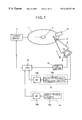
- FIG. 7 is a drawing showing a shock detector voltage profile and a VCM current profile when a shock is received during loading in the disk drive of embodiment 1 of the present invention
- FIG. 8 is a flowchart showing the unloading sequence in the disk drive of embodiment 1 of the present invention.
- FIG. 9 is a drawing showing the configuration of the disk drive of embodiment 2 of the present invention.
- FIG. 10 is a flowchart showing the loading sequence in the disk drive of embodiment 2 of the present invention.
- FIG. 11 is a flowchart showing the unloading sequence due to a spindle rotational speed abnormality in the disk drive of embodiment 3 of the present invention.
- FIG. 12 is a flowchart showing the spindle rotational speed change sequence in the disk drive of embodiment 4 of the present invention.
- FIG. 13 is a drawing showing the configuration of the disk drive of embodiment 5 of the present invention.
- FIG. 14 is a drawing showing the configuration of the disk drive of embodiment 6 of the present invention.
- FIG. 1 is a drawing showing the configuration of the disk drive of embodiment 1 of the present invention.
- the disk drive shown in FIG. 1 has a disk 1 , a spindle 2 which is rotated by a spindle motor (not shown), an actuator 3 , a head/slider 4 , a VCM coil 5 , a ramp 6 , a crash stop 7 , a CPU 10 , a spindle driver 11 , a VCM driver 12 , an actuator velocity detecting circuit (or detector) 13 , and a shock sensor 14 .
- the disk 1 which is the data recording medium, is secured to the spindle 2 .
- the spindle motor rotates the disk 1 .
- the head/slider 4 which has transducer heads that record data on the disk 1 and read data from the disk 1 , and the VCM coil 5 are both mounted in the actuator 3 .
- the VCM coil 5 together with a permanent magnet (not shown), constitutes a voice coil motor (VCM).
- VCM voice coil motor
- This VCM swivels the actuator 3 .
- the ramp 6 supports the head arm 3 when the head/slider 4 is unloaded and the actuator 3 is in the withdrawn position.
- the actuator, VCM, and ramp constitute a load/unload mechanism that loads the head/slider 4 onto the disk, and unloads it from the disk to the withdrawn position.
- the spindle driver 11 drives the spindle motor according to commands from the CPU 10 .
- the VCM driver 12 feeds driving current to the VCM coil 5 according to commands from the CPU 10 , driving the actuator 3 .
- the actuator velocity detecting circuit 13 which has a velocity voltage detecting circuit 13 a and an AD converter 13 b , detects the load/unload the actuator angular velocity.
- the shock sensor 14 which has a shock sensing element 14 a and an AD converter 14 b , senses shock received by the disk drive.
- a feature of the disk drive of embodiment 1 is that if it senses shock with a predetermined level (threshold) or greater during the loading of the head/slider 4 , it stops loading the head/slider 4 and performs unloading, then recommences loading after a delay. Another feature is that if it senses shock with a predetermined level or greater during the unloading of the head/slider 4 by velocity-controlled driving, it stops the velocity-controlled unloading and unloads the head/slider 4 by forced driving (driving without control of velocity).
- the CPU 10 , actuator velocity detecting circuit 13 , and shock sensor 14 constitute a head mechanism controller that controls the above load/unload mechanism through the VCM driver 12 .
- the CPU 10 has a first decision means that decides whether or not a shock sensed by the shock sensor 14 during loading of the head/slider 4 equals or exceeds a first threshold level, and a first load/unload control means that, if the shock equals or exceeds the first threshold level, causes loading to stop, causes unloading of the head/slider 4 to be performed, and causes loading to be performed again when unloading is finished.
- the CPU 10 also directs forced driving of the actuator 3 , or directs velocity-controlled driving of the head arm 3 according to a load/unload velocity detected by the actuator velocity detecting circuit 13 .
- the CPU 10 has a second decision means that decides whether or not a shock sensed by the shock sensor 14 during the unloading of the head/slider 4 by velocity-controlled driving equals or exceeds a second threshold level, and a second load/unload control means that, if the above shock equals or exceeds the second threshold level, causes velocity-controlled driving to be stopped, and causes unloading of the head/slider 4 to be performed by forced driving.
- the above means are based, for example, on program code stored in memory elements which may be in the CPU 10 and which is executed by the CPU.
- the CPU constitutes a spindle motor controller that controls the spindle motor through the spindle driver 11 .
- FIG. 2 is a drawing describing the loading and unloading of the head/slider 4 : (a) is a top plan view; (b) is a sectional view, including the ramp 6 and a protrusion 3 b formed in the actuator 3 .
- the actuator 3 swivels around a swivel shaft 3 a when driving current is fed to the VCM coil 5 .
- the clockwise swiveling direction is the unload direction
- the counterclockwise swiveling direction is the load direction.
- the protrusion 3 b formed in the actuator 3 makes contact with a parking surface 6 a of the ramp 6 .
- the coil supporting member 3 c of the actuator 3 is also in contact with the crash stop 7 , or very close.
- the actuator 3 in FIG. 1 and FIG. 2 swivels in the above load direction, moving the head/slider 4 onto the rotating disk 1 (into the space over the disk 1 ).
- the protrusion 3 b slides over the surface of the ramp 6 at this time, leaving from the inclined surface 6 d.
- the position of the actuator 3 when the head/slider 4 is loaded is shown in FIG. 1 .
- the actuator 3 swivels in the unload direction, and the protrusion 3 b slides over the surface of the ramp 6 in the unload direction, reaching the parking surface 6 a (see FIG. 2 ).
- FIG. 3 is a drawing showing the configuration of the head mechanism controller in the disk drive of embodiment 1.
- the head mechanism controller shown in FIG. 3 comprises the CPU 10 , actuator velocity voltage detecting circuit 13 a , AD converter 13 b , shock sensing element 14 a , and AD converter 14 b , as described above.
- Rvcm indicates the equivalent resistance of the coil
- Evcm indicates the counter-electromotive force generated in the coil when the coil moves.
- the actuator velocity voltage detecting circuit 13 a is a circuit that outputs a voltage proportional to the counterelectromotive force Evcm of the VCM coil 5 .
- the actuator velocity voltage detecting circuit 13 a comprises, for example, resistors Rsens, R 0 , and Rg, a first differential section formed by an op-amp OP 1 , resistors R 1 to R 6 , a capacitor C, a second differential section formed by an op-amp OP 2 , a REF terminal to which a reference voltage Vref is applied, and an OUT terminal.
- the VCM coil 5 is inserted between nodes N 1 and N 2
- resistor Rsens is inserted between nodes N 2 and N 3 .
- Nodes N 1 , N 2 and N 3 are respectively connected to terminals D 1 , S, and D 2 of the VCM driver 12 .
- the driving current of the VCM coil 5 is supplied from the VCM driver 12 , mainly by the following route:
- terminal D 1 VCM coil 5 —resistor Rsens—terminal D 2 .
- the voltage Vout at the OUT terminal is made proportional to the counter-electromotive force Evcm by setting values of resistors Rsens, R 0 , and Rg in relation to the coil resistance Rvcm so that
- Rvcm/Rsens Rg/R 0 .
- the magnitude of the counter-electromotive force Evcm is proportional to the angular velocity of the actuator 3 , and thus to the velocity of the head/slider 4
- the magnitude of the output voltage vout of the actuator velocity voltage detecting circuit 13 a is proportional to the velocity of the head/slider 4 .
- a voltage thus proportional to the velocity of the head/slider 4 is referred to as a velocity voltage.
- This velocity voltage Vout is converted to digital data by AD converter 13 b , and input to the CPU 10 .
- the shock sensing element 14 a is immovably mounted in the disk drive, and outputs a voltage (shock voltage) proportional to the magnitude of a shock.
- An acceleration sensor using a piezoelectric body (piezo-element), for example, is used as the shock sensing element 14 a .
- the shock voltage output from the shock sensing element 14 a is converted to digital data by AD converter 14 b , and input to the CPU 10 .
- Velocity-controlled driving drives the actuator 3 so that the head velocity has a predetermined profile (or predetermined value); here, the actuator 3 will be driven at a constant velocity.
- the CPU 10 controls the driving current value from the VCM driver 12 to the VCM coil 5 according to the head velocity detected by the actuator velocity detecting circuit 13 .
- Forced driving drives the actuator 3 by feeding driving current with a predetermined profile (or predetermined value) to the VCM coil 5 , regardless of the head velocity; here, a constant driving current is fed to the VCM coil to drive the actuator 3 .
- the purpose of loading by velocity-controlled driving is to move the head/slider 4 onto the disk 1 with a predetermined velocity. Loading by velocity-controlled driving is essential in order to prevent accidental landing.
- the purpose of unloading by velocity-controlled driving is to have the actuator 3 contact the ramp 6 at a predetermined velocity.
- FIG. 4 is a drawing showing an example of a profile of the driving current (VCM current) Ivcm fed to the VCM coil 5 in loading/unloading by velocity-controlled driving: (a) is a VCM current profile for loading; (b) is a VCM current profile for unloading.
- VCM current driving current
- FIG. 4 ( a ) loading starts at time t 0 , and ends at time t 1 by moving the head/slider 4 onto the disk 1 with a predetermined velocity.
- the profile of the VCM current Ivcm has a pulse current portion (the first push portion) P 1 , and a velocity-controlled current portion C 1 that varies continuously.
- the actuator 3 overcomes static friction with the parking surface 4 a of the ramp 6 shown in FIG. 2, and starts sliding in the load direction; by means of the velocity-controlled current portion C 1 , it leaves the inclined surface 6 d of the ramp 6 with a predetermined velocity, and moves onto the disk 1 .
- the actuator 3 ascends the inclined surface 6 b of the ramp 6 by means of C 11 in the velocity-controlled current portion C 1 , slides over the plateau 6 c by means of C 12 , and descends the inclined surface 6 d by means of C 13 .
- the actuator 3 touches the ramp 6 at time t 0 , and unloading ends at time t 1 .
- the VCM current profile has a continuously varying velocity-controlled current portion C 2 and a pulse current portion (last push portion) P 2 .
- the actuator 3 slides over the inclined surface 6 d , plateau 6 c , and inclined surface 6 b of the ramp 6 by means of the velocity-controlled current portion C 2 , reaches the parking surface 6 a , and is securely unloaded to the withdrawn position by means of the pulse current portion P 2 .
- FIG. 5 is a drawing showing an example of a VCM current profile when an external shock is received during loading by velocity-controlled driving, but loading is continued.
- the shock is received at time t 2 .
- the velocity-controlled current portion C 3 shows a case in which velocity control is destabilized by a momentary change in head velocity due to the shock, and excessively high VCM current is fed to the VCM coil 5 from time t 2 to time t 1 . There is risk at this time that the head/slider 4 will move onto the disk 1 with an abnormal velocity before time t 1 .
- the disk drive of embodiment 1 receives a shock while performing loading or unloading by velocity-controlled driving, however, it can avoid the above type of accidental landing by promptly performing unloading by forced driving.
- FIG. 6 is a flowchart showing the load sequence of the head/slider 4 in the disk drive of embodiment 1.
- the CPU 10 commences loading of the head/slider 4 by velocity-controlled driving in step S 2 , by means of a control loop comprising the VCM driver 12 , VCM coil 5 , and actuator velocity detecting circuit 13 .
- step S 3 the first decision means in the CPU 10 decides whether or not a shock that requires loading to be stopped has been received, by comparing the shock voltage from the shock sensor 14 with the first threshold level. If the decision in step S 3 is that a shock requiring loading to be stopped has not been received, in step S 4 the CPU 10 decides whether or not loading is finished, and returns to step S 3 if loading is not finished, or proceeds to step S 7 , completing the load sequence, if loading is finished.
- step S 3 If the decision in step S 3 is that a shock requiring loading to be stopped has been received, the first load/unload control means in the CPU 10 stops loading in step S 5 , causes unloading to be performed by forced driving in step S 6 , and returns the actuator 3 to the withdrawn position.
- the unloading in step S 6 ends, a return is made to step S 2 , and the first load/unload control means commences reloading.
- FIG. 7 is a drawing showing examples of a profile of the shock voltage Vsh of the shock sensing element 14 b and a VCM current profile when a shock is received during loading by velocity-controlled driving in the disk drive of embodiment 1: (a) is the shock voltage profile, and (b) is the VCM current profile.
- the disk drive starts loading the actuator 3 at time t 0 , stops loading at time t 2 because an external shock is received, performs an emergency unloading from time t 2 to time t 3 , starts loading again at time t 3 , and finishes loading at time t 4 .
- Pulse current portions P 3 and P 5 are the same as pulse current portion P 1 in FIG. 4 ( a ); pulse current portion P 4 is the same as pulse current portion P 2 in FIG. 4 ( b ).
- the velocity-controlled current portion C 5 is substantially the same as velocity-controlled current portion C 1 in FIG. 4 ( a ).
- the level of the shock voltage at time t 2 shown in FIG. 7 ( a ) is greater than the first threshold level Vt 1 , so unloading of the head/slider 4 is performed by forced driving (see steps S 3 , S 5 , and S 6 in FIG. 6 ).
- the resulting driving current is the constant-current portion J, which has reverse polarity to the velocity-controlled current portion C 4 , as shown in FIG. 7 ( b ).
- the actuator 3 Due to the constant-current portion J, the actuator 3 , which was sliding over the surface of the ramp 6 in the load direction due to the velocity-controlled current portion C 4 , reverses its sliding direction and returns to the withdrawn position at time t 3 . From time t 3 to time t 4 , the head/slider 4 is loaded onto the disk 1 by the pulse current portion P 5 and velocity-controlled current portion C 5 .
- FIG. 8 is a flowchart showing the unload sequence of the head/slider 4 in the disk drive of embodiment 1.
- unloading by velocity-controlled driving also starts in step S 12 .
- the second decision means in the CPU 10 decides whether or not a shock that requires velocity-controlled driving to be stopped has been received, by comparing the shock voltage from the shock sensor 14 with the second threshold level. If the decision in step S 13 is that a shock requiring velocity-controlled driving to be stopped has not been received, in step S 14 the CPU 10 decides whether or not unloading is finished, and proceeds to step S 17 , completing the load sequence, if unloading is finished.
- step S 13 If the decision in step S 13 is that a shock requiring velocity-controlled driving to be stopped has been received, the second load/unload control means in the CPU 10 stops velocity-controlled driving in step S 15 , causes unloading to be performed by forced driving in step S 16 , returns the actuator 3 to the withdrawn position, and completes the unload sequence in step S 17 .
- a counter which tracks a number of aborted attempts in a selected time period can be included and if loading has been aborted a predetermined number of times due to shock sensing, the drive may stop trying to load the heads.
- the program code executed by the CPU may be used for ending attempts to load if the number of aborted attempts has reached a predetermined number. It is also permissible to decide whether or not loading must be stopped or velocity-controlled driving must be stopped by considering the position of the head/slider 4 on the ramp 6 when the shock is received, and other factors, in addition to the level of the shock.
- FIG. 9 is a drawing showing the configuration of the disk drive of embodiment 2 of the present invention.
- the disk drive shown in FIG. 9 has a disk 1 , a spindle 2 , a spindle motor (not shown), an actuator 3 , a head/slider 4 , a VCM coil 5 , a ramp 6 , a crash stop 7 , a CPU 20 , a spindle driver 11 , a VCM driver 12 , and a rotational speed detecting circuit 21 .
- Elements in FIG. 9 that are the same as in FIG. 1 have the same reference numerals.
- a feature of the disk drive of embodiment 2 is that it confirms that the rotational speed of the spindle motor is within a predetermined tolerance range in relation to a speed setting before performing the loading of the head/slider 4 .
- An abnormal rotational speed of the spindle motor (a speed outside the tolerance range) contains the possibility of abnormal stopping of the spindle motor. Abnormal stopping of the spindle motor during loading of the actuator always invites accidental landing. An abnormal rotational speed of the spindle motor during loading of the actuator also risks inviting an accidental landing.
- the rotational speed detecting circuit 21 detects the rotational speed of the spindle motor, and sends the detected value to the CPU 20 .
- the CPU 20 and rotational speed detecting circuit 21 constitute a head mechanism controller that controls the load/unload mechanism through the VCM driver 12 .
- the CPU 20 has a decision means that decides whether or not the rotational speed detected by the rotational speed detecting circuit 21 is within a predetermined tolerance range in relation to a rotational speed setting, and an entry control means that allows loading of the head/slider 4 to be performed only if the detected rotational speed is within the tolerance range.
- the tolerance range is, for example, +/ ⁇ 0.3% of a rotational speed setting of 4000 rpm.
- the above means are based, for example, on program code stored in memory elements in the CPU 20 .
- the CPU 20 also constitutes a spindle motor controller that controls the spindle motor through the spindle driver 11 .
- FIG. 10 is a flowchart showing the load sequence of the head/slider 4 in the disk drive shown in FIG. 9 .
- the load sequence starts in step S 21 , first the rotational speed of the spindle motor is detected by the rotational speed detecting circuit 21 in step S 22 .
- the decision means in the CPU 20 decides whether or not the detected spindle rotational speed is within the tolerance range; if the spindle motor is turning normally and the spindle rotational speed is within the tolerance range in step S 23 , then the entry control means in the CPU 20 causes the loading of the head/slider 4 to be performed in step S 24 , and the load sequence ends in step S 25 .
- the loading in step S 24 is performed by, for example, the velocity-controlled driving described in embodiment 1 above.
- step S 23 If the spindle motor is not turning normally and the spindle rotational speed is not within the tolerance range in step S 23 , a return is made to step S 22 .
- the loop comprising steps S 22 and S 23 is repeated, without loading being performed, until it is confirmed that the spindle motor is turning normally.
- the configuration of the disk drive of embodiment 3 of the present invention has a CPU 30 replacing the CPU 20 in the disk drive of the above embodiment 2, shown in FIG. 9 .
- a feature of the disk drive of embodiment 3 is that when the head/slider 4 has been loaded and operations such as the reading or writing of data are being performed, if the rotational speed of the spindle motor departs from a predetermined tolerance range in relation to a rotational speed setting, an unloading of the head/slider 4 is performed.
- An abnormal rotational speed of the spindle motor (a speed outside the tolerance range) contains the possibility of abnormal stopping by the spindle motor. Abnormal stopping of the spindle motor while operations are being performed (when the head/slider 4 is positioned over the disk 1 ) always invites accidental landing. Abnormal rotational speed of the spindle motor while operations are being performed also risks inviting an accidental landing. Accidental landings due to abnormalities of the spindle motor while operations are being performed can be prevented by causing unloading of the head/slider 4 to be performed if the rotational speed of the spindle motor departs from the tolerance range.
- the CPU 30 and rotational speed detecting circuit 21 constitute a head mechanism controller that controls the load/unload mechanism through the VCM driver 12 .
- the CPU 30 has a decision means that decides whether or not the rotational speed detected by the rotational speed detecting circuit 21 is outside a predetermined tolerance range in relation to a rotational speed setting, and a withdrawal control means that causes an unloading of the head/slider 4 to be performed if the detected rotational speed is outside the tolerance range.
- the tolerance range is, for example, +/ ⁇ 0.6% of a rotational speed setting of 4000 rpm.
- the above means are based, for example, on program code stored in memory elements in the CPU 30 .
- the CPU 30 also constitutes a spindle motor controller that controls the spindle motor through the spindle driver 11 .
- FIG. 11 is a flowchart showing the unload sequence due to a spindle rotational speed abnormality in the disk drive of embodiment 3.
- the rotational speed of the spindle motor is detected by the rotational speed detecting circuit 21 in step S 32 ; in step S 33 , the decision means in the CPU 30 decides whether or not the detected spindle rotational speed is outside the tolerance range, and returns to step S 32 if it is within the tolerance range. While operations are being performed, the spindle rotational speed is thus monitored continuously by the loop comprising steps S 32 and S 33 .
- step S 34 the CPU 30 stops the operations; in step S 35 , the withdrawal control means in the CPU 30 causes an unloading of the head/slider 4 to be performed; and the unload sequence due to the spindle rotational speed abnormality ends in step S 36 .
- Either unloading by velocity-controlled driving or unloading by forced driving can be used for the unloading in step S 35 .
- the head mechanism controller in embodiment 3 above can also be employed in CSS-type disk drives.
- the configuration of the disk drive of embodiment 4 of the present invention has a CPU 40 replacing the CPU 20 in the disk drive of the above embodiment 2, shown in FIG. 9 .
- a feature of the disk drive of embodiment 4 is that when changing the spindle rotational speed, it unloads the head/slider 4 before performing the change of the spindle rotational speed, then confirms that the spindle rotational speed has stabilized at the new rotational speed setting (is within a predetermined tolerance range in relation to the new rotational speed setting) before loading the head/slider 4 again.
- Changing the rotational speed of the spindle motor contains a substantial possibility of rotational speed abnormalities, or of abnormal stopping of the spindle motor. If the head/slider 4 is positioned over the disk 1 when the spindle rotational speed is changed, there is a substantial risk of bringing about an accidental landing.
- Changes of the spindle rotational speed are performed in transitions to low-rpm burnishing and low-rpm operations such as low-rpm reading, or on return from low-rpm operations to operations at the normal rotational speed.
- Low-rpm burnishing is a process in which the spindle rotational speed is reduced below normal, reducing the flying height of the head/slider 4 , and projections from the surface of the disk 1 are removed by means of the head/slider 4 .
- a low-rpm operation is a process of reducing the flying height of the head/slider 4 and reading or writing data.
- the CPU 40 and rotational speed detecting circuit 21 constitute a head mechanism controller that controls the load/unload mechanism through the VCM driver 12 .
- the CPU 40 is characterized in having a withdrawal control means that causes unloading of the head/slider 4 to be performed if notification that a rotational speed change of the rotational speed setting of the spindle motor from a first rotational speed (normal rotational speed) to a second rotational speed (low-rpm) will be performed is received from a higher-order controller of the CPU 40 , or from another means in the CPU 40 ; a rotational speed change control means that causes the change of the rotational speed setting of the spindle motor to be performed; a decision means that decides whether or not the rotational speed detected by the rotational speed detecting circuit 21 is outside a predetermined tolerance range in relation to the second rotational speed; and an entry control means that causes loading of the head/slider 4 to be performed if the detected rotational speed is within the tolerance range.
- the tolerance range is, for example, +/ ⁇ 0.3% of the second rotational speed, which is 3000 rpm.
- the above means are based, for example, on program code stored in memory elements in the CPU 40 .
- the CPU 40 also constitutes a spindle motor controller that controls the spindle motor through the spindle driver 11 .
- the above rotational speed change control means causes the change of the spindle rotational speed to be performed by the spindle motor controller.
- FIG. 12 is a flowchart showing the spindle rotational speed change sequence in the disk drive of embodiment 4.
- the sequence shown in FIG. 12 can be employed either when the spindle rotational speed is reduced (for example, in a transition from operations at the normal rotational speed to low-rpm operations), or when the spindle rotational speed is increased (for example, in a transition from low-rpm operations to operations at the normal rotational speed).
- step S 41 When normal-rotational-speed operations are terminated in step S 41 in accordance with a notification of a change of the spindle rotational speed, and the spindle rotational speed change sequence begins, first, the withdrawal control means in the CPU 40 performs an unloading of the head/slider 4 in step S 42 .
- This unloading may be either unloading by velocity-controlled driving or unloading by forced driving.
- step S 43 the rotational speed change control means in the CPU 40 causes the change of the spindle rotational speed to be performed by the spindle motor controller.
- the rotational speed of the spindle motor thereby changes from the first rotational speed toward the second rotational speed.
- step S 44 the CPU 40 detects the rotational speed of the spindle motor by means of the rotational speed detecting circuit 21 ; in step S 45 , the decision means in the CPU 40 decides whether or not the detected rotational speed is within the tolerance range in relation to the second rotational speed, and returns to step S 44 if the detected rotational speed has not been changed normally and is outside the tolerance range.
- the loop comprising steps S 44 and S 45 is accordingly repeated until it is confirmed that the rotational speed of the spindle motor has been changed normally.
- step S 45 If, in step S 45 , it is confirmed that the rotational speed of the spindle motor has been changed normally and the spindle rotational speed is within the tolerance range, then in step S 46 , the entry control means in the CPU 40 causes loading of the head/slider 4 to be performed.
- the spindle rotational speed change sequence is completed in step S 47 , when the loading of the head/slider 4 ends, and a transition is made, for example, to low-rpm operations.
- the head mechanism controller in embodiment 4 above can also be employed in CSS-type disk drives.
- FIG. 13 is a drawing showing the configuration of the disk drive of embodiment 5 of the present invention.
- the disk drive shown in FIG. 13 has a disk 1 , a spindle motor, an actuator 3 , a head/slider 4 , a VCM coil 5 , a ramp 6 , a crash stop 7 , a CPU 50 , a spindle driver 11 , a VCM driver 12 , a supervisory timer 51 , a timer resetting circuit 52 , and a withdrawal control auxiliary circuit 53 .
- Elements in FIG. 13 that are the same as in FIG. 1 have the same reference numerals.
- the supervisory timer 51 has a counter circuit 51 a that increments, for example, at fixed time intervals, is reset by a reset pulse Pr, and upon overflowing, outputs a time-up signal Tu at the “H” level.
- This counter 51 a is, for example, a 16-bit counter circuit having a 1-bit overflow bit 51 b , as shown in FIG. 13 .
- the bit value of the overflow bit 51 b becomes the time-up signal Tu.
- the overflow bit 51 b changes from “0” to “1” (from the “L” level to the “H” level).
- the timer resetting circuit 52 outputs a reset pulse Pr each time the disk 1 makes a predetermined number of rotations, and has, for example, a circuit that detects one rotation of the disk 1 , a counter circuit that increments each time one rotation of the disk 1 is detected, and a circuit that outputs the reset pulse Pr when the counter output reaches a predetermined value, also resetting the counter circuit.
- the withdrawal control auxiliary circuit 53 has, for example, a transistor 53 a that turns on when the time-up signal Tu is at the “H” level.
- the time-up signal Tu is input to the base terminal of transistor 53 a , the emitter terminal of transistor 53 a is grounded, and the collector terminal is connected to the Su terminal of the VCM driver 12 .
- the VCM driver 12 performs an unloading of the head/slider 4 when the Su terminal is grounded.
- the CPU 50 , supervisory timer 51 , timer resetting circuit 52 , and withdrawal control auxiliary circuit 53 constitute a head mechanism controller that controls the load/unload mechanism through the VCM driver 12 .
- the CPU 50 also constitutes a spindle motor controller that controls the spindle motor through the spindle driver 11 .
- the CPU 50 has an entry/withdrawal control means, belonging to the head mechanism controller, for causing loading/unloading to be performed, and a rotation control means, belonging to the spindle motor controller, for causing the spindle motor to be driven. These means are based on program code stored in the CPU 50 .
- a feature of the disk drive of embodiment 5 is that it supervises the spindle rotational speed by means of the supervisory timer 51 and timer resetting circuit 52 , and performs an unloading of the head/slider 4 by means of the withdrawal control auxiliary circuit 53 , irrespective of the program-code-based means, if the spindle rotational speed drops abnormally. Even if the program-code-based means malfunction, accidental landings can be prevented by performing an unloading, irrespective of the program-code-based means, when the spindle rotational speed drops.
- the timer resetting circuit 52 When the disk 1 is being rotated at a normal rotational speed by the spindle motor, the timer resetting circuit 52 outputs reset pulses Pr at shorter time intervals than those at which the supervisory timer 51 times up.
- the overflow bit 51 b of the supervisory timer 51 is therefore always at the “L” level, and the transistor 53 a in the withdrawal control auxiliary circuit 53 is always off.
- the time interval between reset pulses Pr from the timer resetting circuit 52 lengthens; if the supervisory timer 51 times out, then the overflow bit 51 b , namely the time-out signal Tu, changes from the “L” level to the “H” level.
- the time-up signal Tu changes to the “H” level
- transistor 53 a turns on, the Su terminal of the VCM driver 12 is grounded, and the VCM driver 12 is reset.
- the VCM driver 12 thereupon activates a retract circuit, not shown in the drawing, causing the retract circuit to perform the unloading of the head/slider 4 .
- the above retract circuit is a circuit known in the prior art that generates driving current from the counter-electromotive force generated by the spindle motor for feeding to the VCM coil 5 . Even if the entry/withdrawal control means in this head mechanism controller and the rotation control means in the spindle motor controller fail to operate normally, due to program-code misbehavior or the like, and stop the spindle motor while the head/slider 4 is positioned over the disk 1 , the head/slider 4 will be unloaded by the supervisory timer 51 , timer resetting circuit 52 , and withdrawal control auxiliary circuit 53 before the spindle motor halts.
- the head mechanism controller in embodiment 5 above can also be employed in CSS-type disk drives.
- FIG. 14 is a drawing showing the configuration of the disk drive of embodiment 6 of the present invention.
- the disk drive shown in FIG. 14 has a disk 1 , a spindle motor, an actuator 3 , a head/slider 4 , a VCM coil 5 , a ramp 6 , a crash stop 7 , a CPU 60 , a spindle driver 11 , a VCM driver 12 , a clock signal generating circuit 61 , a switching circuit 62 , and a signal supply controller 63 .
- Elements in FIG. 14 that are the same as in FIG. 1 have the same reference numerals.
- the clock generating circuit 61 generates, for example, a 40-MHZ clock Ck.
- the clock Ck is supplied as a driving source signal to the spindle driver 11 through the switching circuit 62 .
- the spindle driver 11 uses the clock Ck to generate driving signals for the spindle motor.
- the switching circuit 62 opens and closes according to a control signal Sc from the signal supply controller 63 .
- the signal supply controller 63 has a data receiving section 63 a that receives word data from the CPU 60 , and a supply control section 63 c that opens the switching circuit 62 by means of the control signal Sc, causing the supply of the clock Ck to the spindle driver 11 to be stopped, when a key word is received by the data receiving section 63 a ; that is, when the above word data matches a pre-stored key word.
- the data receiving section 63 a has, for example, a 2-bit register 63 b .
- One data word comprises, for example, combined parallel/serial 2 ⁇ 2-bit data.
- One word that is, is a combined parallel/serial data word comprising two bits of parallel data b 11 and b 12 (not shown) received by register 63 b , and the two bits of parallel data b 21 and b 22 (not shown) received by register 63 b following this parallel data b 11 and b 12 .
- the key word pre-stored in the supply control section 63 c is a data word in which, for example, able, “b 12 , b 21 , b 22 ” equals “0, 1, 1, 0.”
- the switching circuit 62 is opened by the control signal Sc, and the supply of the clock Ck to the spindle driver 11 is stopped.
- the spindle driver 11 can no longer drive the spindle motor, so the spindle motor stops, whereby the rotation of the disk 1 stops.
- the stopping of the supply of the clock Ck to the spindle driver 11 is performed, for example, in the power-saving mode.
- a feature of the signal supply controller 63 of the present invention is that it stops the supply of the clock Ck when a key word is received.
- the risk that a key word might be sent by mistake to the signal supply controller 63 , due to program-code misbehavior or the like in the CPU 60 is smaller than the risk of the mistaken sending of predetermined bit data.
- the risk of mistaken sending of a key word can be reduced without limit by increasing the number of bits in the word data.
- Accidental landings due to malfunctions of the signal supply controller can accordingly be prevented by controlling the supply of the clock Ck by a key word, thus avoiding malfunctions of the signal supply controller.
- accidental landings due to malfunctions of the signal supply controller can be prevented by controlling the supply of the clock Ck to the spindle driver 11 by using a signal supply controller 63 that stops the supply of the clock Ck upon receiving a key word.
- the word unit may be n ⁇ m bits (where n and m are positive integers).
- the signal supply controller 63 can be employed not only for the supply of the clock, but also for the supply of power supply and other driving source signals. Also, the signal supply controller 63 can be employed not only for the spindle driver 11 , but also for the supply of driving source signals to the driving circuits of other operating mechanisms. In addition, the signal supply controller 63 can also be employed in CSS-type disk drives.
- the head mechanism controller of the present invention and a disk drive using this controller, during the loading of the transducer head, if a shock requiring loading to be stopped is sensed, loading is stopped and unloading is performed, and during the unloading of the transducer head with velocity control, if a shock requiring velocity control to be stopped is sensed, velocity control is stopped and unloading without control of the velocity of the transducer head is performed, with the effect that accidental landings can be prevented even if a shock is received during loading or unloading, as described above.
- the effect of preventing accidental landings due to rotational speed abnormalities of the recording medium is obtained by confirming that the rotational speed of the recording medium is within a predetermined range before causing the transducer head to move into a predetermined area on the recording medium, and by causing the transducer head to withdraw from the predetermined area on the recording medium if the rotational speed of the recording medium departs from the predetermined range.
- the effect of preventing accidental landings due to rotational speed abnormalities of the recording medium when the rotational speed is changed is obtained by causing unloading of the transducer head to be performed before allowing the change of the spindle rotational speed of the recording medium to be performed, and by confirming that the spindle rotational speed is within a predetermined range in relation to the second rotational speed, then causing the loading of the transducer head to be performed.
- the effect of preventing accidental landings, even if the withdrawal control means malfunctions is obtained by resetting a supervisory timer each time the recording medium makes a predetermined number of rotations, and by causing a withdrawal of the transducer head to be performed, irrespective of the withdrawal control means, if the supervisory timer times up.
- malfunction of the signal supply controller can be avoided by stopping the supply of driving source signals when a key word is received, with the effect that accidental landings due malfunction of the signal supply controller can be prevented.
Abstract
Description
Claims (2)
Applications Claiming Priority (2)
| Application Number | Priority Date | Filing Date | Title |
|---|---|---|---|
| JP9167296A JPH1116259A (en) | 1997-06-24 | 1997-06-24 | Head mechanism controller and signal supply control device and disk drive device |
| JP9-167296 | 1997-06-24 |
Publications (1)
| Publication Number | Publication Date |
|---|---|
| US6236527B1 true US6236527B1 (en) | 2001-05-22 |
Family
ID=15847130
Family Applications (1)
| Application Number | Title | Priority Date | Filing Date |
|---|---|---|---|
| US09/103,758 Expired - Lifetime US6236527B1 (en) | 1997-06-24 | 1998-06-24 | Disk drive with actuator load/unload controller |
Country Status (2)
| Country | Link |
|---|---|
| US (1) | US6236527B1 (en) |
| JP (1) | JPH1116259A (en) |
Cited By (50)
| Publication number | Priority date | Publication date | Assignee | Title |
|---|---|---|---|---|
| US20020054447A1 (en) * | 2000-11-06 | 2002-05-09 | Masayuki Kurita | Magnetic disk apparatus and method of controlling the same |
| US6388832B1 (en) * | 1999-04-27 | 2002-05-14 | International Business Machines Corporation | Method and system for providing spindle motor control for head loading in a disk drive |
| US20020089776A1 (en) * | 2000-11-29 | 2002-07-11 | Fujitsu Limited | Disk unit |
| US20020093753A1 (en) * | 2000-12-21 | 2002-07-18 | Masaru Atsumi | Method and apparatus for avoiding collision of head in disk drive |
| US20020135928A1 (en) * | 2000-06-01 | 2002-09-26 | Fujitsu Limited | Disk drive unit and control method for same |
| US6466391B1 (en) * | 1998-05-22 | 2002-10-15 | Fairchild Korea Semiconductor Ltd. | Head retraction circuit |
| US20020154438A1 (en) * | 2001-04-23 | 2002-10-24 | Fujitsu Limited | Load/unload operation control method and storage apparatus |
| US20030035240A1 (en) * | 2001-08-16 | 2003-02-20 | International Business Machines Corporation | Hard disk drive, data storing and reproducing device, head movement controller, and head movement control method |
| US20030053240A1 (en) * | 2001-09-14 | 2003-03-20 | Bruner Curtis H. | Digital device configuration and method |
| US6590736B2 (en) * | 2000-04-17 | 2003-07-08 | Orion Electric Co., Ltd. | Tape or disc record player equipped with standby power-saving means |
| US20030161065A1 (en) * | 2002-01-30 | 2003-08-28 | Masahide Yatsu | Method and apparatus for controlling the actuator of the head-positioning system provided in a disk drive |
| US20030227836A1 (en) * | 2002-05-15 | 2003-12-11 | Funai Electric Co., Ltd. | Optical disk apparatus |
| US20040034724A1 (en) * | 2001-09-14 | 2004-02-19 | Bruner Curtis H. | Digital device configuration and method |
| EP1394799A2 (en) * | 2002-08-28 | 2004-03-03 | Samsung Electronics Co., Ltd. | Method and apparatus for controlling disc drive positioning arm using back-emf |
| US6710964B1 (en) * | 1999-10-12 | 2004-03-23 | Seagate Technology Llc | Ramp load disc drive having a padded slider |
| US6741414B1 (en) * | 1999-06-15 | 2004-05-25 | Tokyo Electron Limited | Joint spindle speed and head position control in rotating media storage systems |
| US20040100718A1 (en) * | 2002-11-23 | 2004-05-27 | Texas Instruments Incorporated | Digital processor controlled method and circuit for retracting a head carriage assembly to a parked position in a mass data storage device, or the like, by actively detecting a collision with a crash stop |
| US20040100717A1 (en) * | 2002-11-23 | 2004-05-27 | Texas Instruments Incorporated | Digital processor controlled method and circuit for retracting a head carriage assembly to a parked position in a mass data storage device, or the like, by actively detecting a desired velocity |
| US20040125493A1 (en) * | 2002-10-03 | 2004-07-01 | International Business Machines Corporation | Magnectic disk protection mechanism, computer system comprising protection mechanism, protection method for magnetic disk, and program for protection method |
| US6791799B2 (en) | 2001-09-14 | 2004-09-14 | Convergent Systems Solutions Llc | Digital device configuration and method |
| US20050018339A1 (en) * | 2003-07-21 | 2005-01-27 | Tanner Brian K. | Method and system for reducing power consumption in a rotatable media data storage device |
| US20050018340A1 (en) * | 2003-07-21 | 2005-01-27 | Tanner Brian K. | Method and system for reducing power consumption in a rotatable media data storage device |
| US6859340B2 (en) | 2001-03-09 | 2005-02-22 | Seagate Technology Llc | Method and device for retracting an actuator |
| US20050141122A1 (en) * | 2003-10-15 | 2005-06-30 | Fujistu Limited | Method and apparatus for head control, and disk-drive apparatus |
| US20050154823A1 (en) * | 2001-09-14 | 2005-07-14 | Bruner Curtis H. | Digital device configuration and method |
| US20050174676A1 (en) * | 2004-02-10 | 2005-08-11 | Signal Electronic Co., Ltd. | Method and device for data protection |
| US20060070439A1 (en) * | 2004-10-02 | 2006-04-06 | Samsung Electronics Co., Ltd. | Method and apparatus for detecting free fall of electronic device |
| US20060164749A1 (en) * | 2005-01-25 | 2006-07-27 | Kabushiki Kaisha Toshiba | Method for retracting head upon interruption of power, and disk drive employing the method |
| US20060221490A1 (en) * | 2005-03-31 | 2006-10-05 | Tan Lee L | Ramp unload in disc drives |
| US20060291086A1 (en) * | 2005-06-28 | 2006-12-28 | Seagate Technology Llc | Adaptive control of head velocity during data storage device startup |
| US20070127151A1 (en) * | 2005-12-07 | 2007-06-07 | Samsung Electronics Co., Ltd | Retract control method of HDD and HDD using the same |
| US20070139811A1 (en) * | 2005-12-21 | 2007-06-21 | Kabushiki Kaisha Toshiba | Method and apparatus for head positioning control in a disk drive |
| WO2007081799A3 (en) * | 2006-01-06 | 2007-10-11 | Cornice Inc | Hard disk drive and stray magnetic field sensor system and associated method |
| US20070251294A1 (en) * | 2005-03-24 | 2007-11-01 | Hitachi, Ltd. | Sensor node for impact detection |
| US20070285826A1 (en) * | 2006-06-09 | 2007-12-13 | Fujitsu Limited | Control apparatus, storage device, and head retracting method |
| US20090268334A1 (en) * | 2008-04-24 | 2009-10-29 | Sayaka Nojiri | Disk drive device and control method of unloading corresponding to fall detection in disk drive device |
| US7619845B2 (en) | 2002-08-28 | 2009-11-17 | Samsung Electronics, Ltd. | Method and apparatus for controlling disc drive using counter-electromotive force |
| US20100067138A1 (en) * | 2008-09-16 | 2010-03-18 | Seagate Technology | Variable spindle speed for ramp unload |
| US7747818B1 (en) | 2006-08-16 | 2010-06-29 | Nvidia Corporation | Media protection notification for serial interface mass storage devices |
| US8775720B1 (en) | 2010-08-31 | 2014-07-08 | Western Digital Technologies, Inc. | Hybrid drive balancing execution times for non-volatile semiconductor memory and disk |
| US8782334B1 (en) * | 2010-09-10 | 2014-07-15 | Western Digital Technologies, Inc. | Hybrid drive copying disk cache to non-volatile semiconductor memory |
| US8917471B1 (en) | 2013-10-29 | 2014-12-23 | Western Digital Technologies, Inc. | Power management for data storage device |
| US8959281B1 (en) | 2012-11-09 | 2015-02-17 | Western Digital Technologies, Inc. | Data management for a storage device |
| US8959284B1 (en) | 2010-06-28 | 2015-02-17 | Western Digital Technologies, Inc. | Disk drive steering write data to write cache based on workload |
| US9058280B1 (en) | 2010-08-13 | 2015-06-16 | Western Digital Technologies, Inc. | Hybrid drive migrating data from disk to non-volatile semiconductor memory based on accumulated access time |
| US9070379B2 (en) | 2013-08-28 | 2015-06-30 | Western Digital Technologies, Inc. | Data migration for data storage device |
| US9141176B1 (en) | 2013-07-29 | 2015-09-22 | Western Digital Technologies, Inc. | Power management for data storage device |
| US9268499B1 (en) | 2010-08-13 | 2016-02-23 | Western Digital Technologies, Inc. | Hybrid drive migrating high workload data from disk to non-volatile semiconductor memory |
| US9401165B1 (en) * | 2014-05-05 | 2016-07-26 | Western Digital Technologies, Inc. | Method and system to monitor magnetic head loading and unloading stability for a data storage system |
| US10714135B1 (en) | 2019-03-29 | 2020-07-14 | Western Digital Technologies, Inc. | Air-bearing surface designs with a curved trailing air flow dam |
Citations (6)
| Publication number | Priority date | Publication date | Assignee | Title |
|---|---|---|---|---|
| US4237501A (en) * | 1978-07-25 | 1980-12-02 | Pertec Computer Corporation | Emergency head unload system for magnetic disk drive |
| JPH05101573A (en) | 1991-10-09 | 1993-04-23 | Kyushu Nippon Denki Software Kk | Magnetic disk device protecting system by pause in access upon detecting of vibration |
| US5227929A (en) * | 1990-11-26 | 1993-07-13 | International Business Machines Corporation | Portable computer hard disk protective reflex system |
| JPH05258496A (en) | 1992-03-13 | 1993-10-08 | Nec Corp | Magnetic disk device |
| JPH05307851A (en) | 1992-05-01 | 1993-11-19 | Canon Inc | Magneto-optical recorder |
| JPH06236644A (en) | 1993-02-08 | 1994-08-23 | Fuji Electric Co Ltd | Head clash preventive method and preventive device for stationary disk device |
-
1997
- 1997-06-24 JP JP9167296A patent/JPH1116259A/en active Pending
-
1998
- 1998-06-24 US US09/103,758 patent/US6236527B1/en not_active Expired - Lifetime
Patent Citations (6)
| Publication number | Priority date | Publication date | Assignee | Title |
|---|---|---|---|---|
| US4237501A (en) * | 1978-07-25 | 1980-12-02 | Pertec Computer Corporation | Emergency head unload system for magnetic disk drive |
| US5227929A (en) * | 1990-11-26 | 1993-07-13 | International Business Machines Corporation | Portable computer hard disk protective reflex system |
| JPH05101573A (en) | 1991-10-09 | 1993-04-23 | Kyushu Nippon Denki Software Kk | Magnetic disk device protecting system by pause in access upon detecting of vibration |
| JPH05258496A (en) | 1992-03-13 | 1993-10-08 | Nec Corp | Magnetic disk device |
| JPH05307851A (en) | 1992-05-01 | 1993-11-19 | Canon Inc | Magneto-optical recorder |
| JPH06236644A (en) | 1993-02-08 | 1994-08-23 | Fuji Electric Co Ltd | Head clash preventive method and preventive device for stationary disk device |
Cited By (110)
| Publication number | Priority date | Publication date | Assignee | Title |
|---|---|---|---|---|
| US6466391B1 (en) * | 1998-05-22 | 2002-10-15 | Fairchild Korea Semiconductor Ltd. | Head retraction circuit |
| US6388832B1 (en) * | 1999-04-27 | 2002-05-14 | International Business Machines Corporation | Method and system for providing spindle motor control for head loading in a disk drive |
| SG91860A1 (en) * | 1999-04-27 | 2002-10-15 | Ibm | Method and system for providing spindle motor control for head loading in a disk drive |
| US6741414B1 (en) * | 1999-06-15 | 2004-05-25 | Tokyo Electron Limited | Joint spindle speed and head position control in rotating media storage systems |
| US6710964B1 (en) * | 1999-10-12 | 2004-03-23 | Seagate Technology Llc | Ramp load disc drive having a padded slider |
| US6590736B2 (en) * | 2000-04-17 | 2003-07-08 | Orion Electric Co., Ltd. | Tape or disc record player equipped with standby power-saving means |
| US6721122B2 (en) * | 2000-06-01 | 2004-04-13 | Fujitsu Limited | Disk drive unit and control method for same |
| US20020135928A1 (en) * | 2000-06-01 | 2002-09-26 | Fujitsu Limited | Disk drive unit and control method for same |
| US20070070550A1 (en) * | 2000-11-06 | 2007-03-29 | Masayuki Kurita | Magnetic disk apparatus and method of controlling the same |
| US6798605B2 (en) * | 2000-11-06 | 2004-09-28 | Hitachi, Ltd. | Magnetic disk apparatus and method of controlling the same |
| US20050013057A1 (en) * | 2000-11-06 | 2005-01-20 | Masayuki Kurita | Magnetic disk apparatus and method of controlling the same |
| US7209309B2 (en) | 2000-11-06 | 2007-04-24 | Hitachi Global Storage Technologies Japan, Ltd. | Magnetic disk apparatus and method of controlling the same |
| US20020054447A1 (en) * | 2000-11-06 | 2002-05-09 | Masayuki Kurita | Magnetic disk apparatus and method of controlling the same |
| US20020089776A1 (en) * | 2000-11-29 | 2002-07-11 | Fujitsu Limited | Disk unit |
| US7019932B2 (en) * | 2000-11-29 | 2006-03-28 | Fujitsu Limited | Disk unit having mechanism for loading and unloading head uniformly in circumferential direction of a disk |
| US20020093753A1 (en) * | 2000-12-21 | 2002-07-18 | Masaru Atsumi | Method and apparatus for avoiding collision of head in disk drive |
| US6859340B2 (en) | 2001-03-09 | 2005-02-22 | Seagate Technology Llc | Method and device for retracting an actuator |
| EP1253582A3 (en) * | 2001-04-23 | 2003-07-30 | Fujitsu Limited | Load/unload operation control method and storage apparatus |
| US20020154438A1 (en) * | 2001-04-23 | 2002-10-24 | Fujitsu Limited | Load/unload operation control method and storage apparatus |
| US7110207B2 (en) * | 2001-04-23 | 2006-09-19 | Fujitsu Limited | Load/unload operation control method and storage apparatus |
| US6914745B2 (en) * | 2001-08-16 | 2005-07-05 | Hitachi Global Storage Technologies Netherlands B.V. | Head movement controlling based on servo generated speed control values |
| US20030035240A1 (en) * | 2001-08-16 | 2003-02-20 | International Business Machines Corporation | Hard disk drive, data storing and reproducing device, head movement controller, and head movement control method |
| US20050180054A1 (en) * | 2001-09-14 | 2005-08-18 | Bruner Curtis H. | Digital device configuration and method |
| US8631196B2 (en) | 2001-09-14 | 2014-01-14 | Benhov Gmbh, Llc | Digital device configuration and method |
| US6791799B2 (en) | 2001-09-14 | 2004-09-14 | Convergent Systems Solutions Llc | Digital device configuration and method |
| US7551382B2 (en) | 2001-09-14 | 2009-06-23 | Bruner Curtis H | Digital device configuration and method |
| US7546411B2 (en) | 2001-09-14 | 2009-06-09 | Bruner Curtis H | Digital device configuration and method |
| US7689785B2 (en) | 2001-09-14 | 2010-03-30 | Bruner Curtis H | Digital device configuration and method |
| US7702847B2 (en) | 2001-09-14 | 2010-04-20 | Bruner Curtis H | Digital device configuration and method |
| US8001321B2 (en) | 2001-09-14 | 2011-08-16 | Benhov Gmbh, Llc | Digital device configuration and method |
| US8312209B2 (en) | 2001-09-14 | 2012-11-13 | Benhov Gmbh, Llc | Digital device configuration and method |
| US9396746B2 (en) | 2001-09-14 | 2016-07-19 | Benhov Gmbh, Llc | Digital device configuration and method |
| US20050154823A1 (en) * | 2001-09-14 | 2005-07-14 | Bruner Curtis H. | Digital device configuration and method |
| US20050154824A1 (en) * | 2001-09-14 | 2005-07-14 | Bruner Curtis H. | Digital device configuration and method |
| US20050160220A1 (en) * | 2001-09-14 | 2005-07-21 | Bruner Curtis H. | Digital device configuration and method |
| US20050166015A1 (en) * | 2001-09-14 | 2005-07-28 | Bruner Curtis H. | Digital device configuration and method |
| US20030053240A1 (en) * | 2001-09-14 | 2003-03-20 | Bruner Curtis H. | Digital device configuration and method |
| US20050182875A1 (en) * | 2001-09-14 | 2005-08-18 | Bruner Curtis H. | Digital device configuration and method |
| WO2003025932A1 (en) * | 2001-09-14 | 2003-03-27 | Cornice, Inc. | Digital device configuration and method |
| US6973535B2 (en) | 2001-09-14 | 2005-12-06 | Cornice, Inc. | Digital device configuration and method |
| US7165139B2 (en) | 2001-09-14 | 2007-01-16 | Cornice, Inc. | Digital device configuration and method |
| US20040034724A1 (en) * | 2001-09-14 | 2004-02-19 | Bruner Curtis H. | Digital device configuration and method |
| US7162577B2 (en) | 2001-09-14 | 2007-01-09 | Cornice, Inc. | Digital device configuration and method |
| US7162578B2 (en) | 2001-09-14 | 2007-01-09 | Cornice, Inc. | Digital device configuration and method |
| US9940025B2 (en) | 2001-09-14 | 2018-04-10 | Benhov Gmbh, Llc | Digital device configuration and method |
| US7149891B2 (en) | 2001-09-14 | 2006-12-12 | Cornice, Inc. | Digital device configuration and method |
| US7106541B2 (en) * | 2001-09-14 | 2006-09-12 | Convergent Systems Solutions, Llc | Digital device configuration and method |
| US20030161065A1 (en) * | 2002-01-30 | 2003-08-28 | Masahide Yatsu | Method and apparatus for controlling the actuator of the head-positioning system provided in a disk drive |
| US20030227836A1 (en) * | 2002-05-15 | 2003-12-11 | Funai Electric Co., Ltd. | Optical disk apparatus |
| US7086068B2 (en) * | 2002-05-15 | 2006-08-01 | Funai Electric Co., Ltd. | Optical disc apparatus which determines tray movement speeds |
| EP1394799A2 (en) * | 2002-08-28 | 2004-03-03 | Samsung Electronics Co., Ltd. | Method and apparatus for controlling disc drive positioning arm using back-emf |
| EP1394799A3 (en) * | 2002-08-28 | 2006-03-01 | Samsung Electronics Co., Ltd. | Method and apparatus for controlling disc drive positioning arm using back-emf |
| US20060209451A1 (en) * | 2002-08-28 | 2006-09-21 | Samsung Electronics Co., Ltd | Method and apparatus for controlling disc drive using counter-electromotive force |
| US7619845B2 (en) | 2002-08-28 | 2009-11-17 | Samsung Electronics, Ltd. | Method and apparatus for controlling disc drive using counter-electromotive force |
| US7064917B2 (en) | 2002-08-28 | 2006-06-20 | Samsung Electronics Co., Ltd. | Method and apparatus for controlling disc drive using counter-electromotive force |
| US20040051993A1 (en) * | 2002-08-28 | 2004-03-18 | Samsung Electronics Co., Ltd. | Method and apparatus for controlling disc drive using counter-electromotive |
| US7561364B2 (en) | 2002-08-28 | 2009-07-14 | Samsung Electronics Co., Ltd. | Method and apparatus for controlling disc drive using counter-electromotive force |
| US7813074B2 (en) * | 2002-10-03 | 2010-10-12 | Hitachi Global Storage Technologies Netherlands B.V. | Magnetic disk protection mechanism, computer system comprising protection mechanism, protection method for magnetic disk, and program for protection method |
| US7042663B2 (en) * | 2002-10-03 | 2006-05-09 | Hitachi Global Storage Technologies Netherlands B.V. | Magnetic disk protection mechanism, computer system comprising protection mechanism, protection method for magnetic disk, and program for protection method |
| US20060139807A1 (en) * | 2002-10-03 | 2006-06-29 | Hitachi Global Storage Technologies | Magnetic disk protection mechanism, computer system comprising protection mechanism, protection method for magnetic disk, and program for protection method |
| US20080259496A1 (en) * | 2002-10-03 | 2008-10-23 | Susumu Shimotono | Magnetic disk protection mechanism, computer system comprising protection mechanism, protection method for magnetic disk, and program for protection method |
| US20040125493A1 (en) * | 2002-10-03 | 2004-07-01 | International Business Machines Corporation | Magnectic disk protection mechanism, computer system comprising protection mechanism, protection method for magnetic disk, and program for protection method |
| US7382566B2 (en) * | 2002-10-03 | 2008-06-03 | Hitachi Global Storage Technologies Netherlands B.V. | Magnetic disk protection mechanism, computer system comprising protection mechanism, protection method for magnetic disk, and program for protection method |
| US20040100717A1 (en) * | 2002-11-23 | 2004-05-27 | Texas Instruments Incorporated | Digital processor controlled method and circuit for retracting a head carriage assembly to a parked position in a mass data storage device, or the like, by actively detecting a desired velocity |
| US20040100718A1 (en) * | 2002-11-23 | 2004-05-27 | Texas Instruments Incorporated | Digital processor controlled method and circuit for retracting a head carriage assembly to a parked position in a mass data storage device, or the like, by actively detecting a collision with a crash stop |
| US20050018340A1 (en) * | 2003-07-21 | 2005-01-27 | Tanner Brian K. | Method and system for reducing power consumption in a rotatable media data storage device |
| US7068455B2 (en) * | 2003-07-21 | 2006-06-27 | Matsushita Electric Industrial Co., Ltd. | Method and system for reducing power consumption in a rotatable media data storage device |
| US20050018339A1 (en) * | 2003-07-21 | 2005-01-27 | Tanner Brian K. | Method and system for reducing power consumption in a rotatable media data storage device |
| US7035032B2 (en) * | 2003-07-21 | 2006-04-25 | Matsushita Electric Industrial Co., Ltd. | Method and system for reducing power consumption in a rotatable media data storage device |
| US20050141122A1 (en) * | 2003-10-15 | 2005-06-30 | Fujistu Limited | Method and apparatus for head control, and disk-drive apparatus |
| US7230787B2 (en) | 2003-10-15 | 2007-06-12 | Fujitsu Limited | Method and apparatus for head control, and disk-drive apparatus |
| US20050174676A1 (en) * | 2004-02-10 | 2005-08-11 | Signal Electronic Co., Ltd. | Method and device for data protection |
| US7328615B2 (en) * | 2004-10-02 | 2008-02-12 | Samsung Electronics Co., Ltd. | Method and apparatus for detecting free fall of electronic device |
| US20060070439A1 (en) * | 2004-10-02 | 2006-04-06 | Samsung Electronics Co., Ltd. | Method and apparatus for detecting free fall of electronic device |
| US7369346B2 (en) * | 2005-01-25 | 2008-05-06 | Kabushiki Kaisha Toshiba | Method for retracting head upon interruption of power, and disk drive employing the method |
| US20060164749A1 (en) * | 2005-01-25 | 2006-07-27 | Kabushiki Kaisha Toshiba | Method for retracting head upon interruption of power, and disk drive employing the method |
| US7290437B1 (en) * | 2005-03-24 | 2007-11-06 | Hitachi, Ltd. | Sensor node for impact detection |
| US20070251294A1 (en) * | 2005-03-24 | 2007-11-01 | Hitachi, Ltd. | Sensor node for impact detection |
| US20060221490A1 (en) * | 2005-03-31 | 2006-10-05 | Tan Lee L | Ramp unload in disc drives |
| US7352523B2 (en) * | 2005-03-31 | 2008-04-01 | Seagate Technology Llc | Ramp unload in disc drives |
| US7542224B2 (en) * | 2005-06-28 | 2009-06-02 | Seagate Technology | Adaptive control of head velocity during data storage device startup |
| US20060291086A1 (en) * | 2005-06-28 | 2006-12-28 | Seagate Technology Llc | Adaptive control of head velocity during data storage device startup |
| US7570449B2 (en) * | 2005-12-07 | 2009-08-04 | Samsung Electronics Co., Ltd. | Retract control method of HDD and HDD using the same |
| US20070127151A1 (en) * | 2005-12-07 | 2007-06-07 | Samsung Electronics Co., Ltd | Retract control method of HDD and HDD using the same |
| US7489468B2 (en) * | 2005-12-21 | 2009-02-10 | Kabushiki Kaisha Toshiba | Method and apparatus for head positioning control in a disk drive |
| US20070139811A1 (en) * | 2005-12-21 | 2007-06-21 | Kabushiki Kaisha Toshiba | Method and apparatus for head positioning control in a disk drive |
| US20100067136A1 (en) * | 2006-01-06 | 2010-03-18 | Benhov Gmbh, Llc. | System including a hard disk drive and stray magnetic field sensor and associated method |
| CN101385085B (en) * | 2006-01-06 | 2012-11-28 | 本霍夫有限公司 | Hard disk drive and stray magnetic field sensor system and associated method |
| US7859789B2 (en) | 2006-01-06 | 2010-12-28 | Charles Partee | System including a hard disk drive and stray magnetic field sensor and associated method |
| WO2007081799A3 (en) * | 2006-01-06 | 2007-10-11 | Cornice Inc | Hard disk drive and stray magnetic field sensor system and associated method |
| US20070285826A1 (en) * | 2006-06-09 | 2007-12-13 | Fujitsu Limited | Control apparatus, storage device, and head retracting method |
| US7529056B2 (en) * | 2006-06-09 | 2009-05-05 | Fujitsu Limited | Control apparatus, storage device, and head retracting method |
| US7747818B1 (en) | 2006-08-16 | 2010-06-29 | Nvidia Corporation | Media protection notification for serial interface mass storage devices |
| US7752351B1 (en) * | 2006-08-16 | 2010-07-06 | Nvidia Corporation | Media protection notification for serial interface mass storage devices |
| US7995302B2 (en) | 2008-04-24 | 2011-08-09 | Hitachi Global Storage Technologies, Netherlands B.V. | Disk drive device and control method of unloading corresponding to fall detection in disk drive device |
| US20090268334A1 (en) * | 2008-04-24 | 2009-10-29 | Sayaka Nojiri | Disk drive device and control method of unloading corresponding to fall detection in disk drive device |
| US7715145B2 (en) * | 2008-09-16 | 2010-05-11 | Seagate Technology Llc | Variable spindle speed for ramp unload |
| US20100067138A1 (en) * | 2008-09-16 | 2010-03-18 | Seagate Technology | Variable spindle speed for ramp unload |
| US8959284B1 (en) | 2010-06-28 | 2015-02-17 | Western Digital Technologies, Inc. | Disk drive steering write data to write cache based on workload |
| US9268499B1 (en) | 2010-08-13 | 2016-02-23 | Western Digital Technologies, Inc. | Hybrid drive migrating high workload data from disk to non-volatile semiconductor memory |
| US9058280B1 (en) | 2010-08-13 | 2015-06-16 | Western Digital Technologies, Inc. | Hybrid drive migrating data from disk to non-volatile semiconductor memory based on accumulated access time |
| US8775720B1 (en) | 2010-08-31 | 2014-07-08 | Western Digital Technologies, Inc. | Hybrid drive balancing execution times for non-volatile semiconductor memory and disk |
| US8782334B1 (en) * | 2010-09-10 | 2014-07-15 | Western Digital Technologies, Inc. | Hybrid drive copying disk cache to non-volatile semiconductor memory |
| US8959281B1 (en) | 2012-11-09 | 2015-02-17 | Western Digital Technologies, Inc. | Data management for a storage device |
| US9141176B1 (en) | 2013-07-29 | 2015-09-22 | Western Digital Technologies, Inc. | Power management for data storage device |
| US9070379B2 (en) | 2013-08-28 | 2015-06-30 | Western Digital Technologies, Inc. | Data migration for data storage device |
| US8917471B1 (en) | 2013-10-29 | 2014-12-23 | Western Digital Technologies, Inc. | Power management for data storage device |
| US9401165B1 (en) * | 2014-05-05 | 2016-07-26 | Western Digital Technologies, Inc. | Method and system to monitor magnetic head loading and unloading stability for a data storage system |
| US10714135B1 (en) | 2019-03-29 | 2020-07-14 | Western Digital Technologies, Inc. | Air-bearing surface designs with a curved trailing air flow dam |
| US10891981B2 (en) | 2019-03-29 | 2021-01-12 | Western Digital Technologies, Inc. | Air-bearing surface designs with a curved trailing air flow dam |
Also Published As
| Publication number | Publication date |
|---|---|
| JPH1116259A (en) | 1999-01-22 |
Similar Documents
| Publication | Publication Date | Title |
|---|---|---|
| US6236527B1 (en) | Disk drive with actuator load/unload controller | |
| US6396652B1 (en) | Apparatus and method for control head unloading on power down in a disk drive | |
| EP1420405B1 (en) | Head retracting method/apparatus, and head actuator control circuit | |
| US6643088B1 (en) | Magnetic disk drive and method of controlling a movement of carriage in an unload operation of head | |
| US6920007B2 (en) | Load/unload method and a magnetic disk drive using the method | |
| US6594102B1 (en) | Apparatus and method for retracting the head on power down in a disk drive | |
| US6108157A (en) | Head mechanism control apparatus, disk drive, and head unload control method | |
| US6867944B1 (en) | Disk drive comprising VCM stall detector for velocity control of an actuator arm | |
| US6690536B1 (en) | Disk drive employing VCM demand current to calibrate VCM IR voltage for velocity control of an actuator arm | |
| JP2000163901A (en) | Calibration method for velocity correction applied to head loading/unloading type disk device | |
| EP0335546A2 (en) | Off-set nulling system and method for computer disk drives | |
| US4755892A (en) | Method of and apparatus for displacing a movable system driven by an electric motor along a given trajectory | |
| US7046475B2 (en) | Apparatus and method for controlling head unload operation in disk drive | |
| US7079337B2 (en) | Bi staple flying height detection by BEMF control profile and data integrity problem protection | |
| US7483233B2 (en) | Method and apparatus for driving VCM unloading HDD head | |
| KR20000071735A (en) | Method and system for providing spindle motor control for head loading in a disk drive | |
| JP2003077240A (en) | Disk device and head loading control method for the device | |
| US7692394B2 (en) | Power supply output control apparatus and method | |
| US6924956B2 (en) | Head loading/unloading control system for use in disk drive apparatus | |
| US7259933B2 (en) | Velocity control system for an actuator assembly | |
| US8693132B1 (en) | Actuator arm unlatching | |
| US20030117741A1 (en) | Method and apparatus for loading head onto disk medium from ramp in disk drive | |
| JP4286110B2 (en) | Disk device, head retracting method, and head actuator control circuit | |
| US7570449B2 (en) | Retract control method of HDD and HDD using the same | |
| JP2000251429A (en) | Magnetic disk device and head unloading method in interruption of power source |
Legal Events
| Date | Code | Title | Description |
|---|---|---|---|
| AS | Assignment |
Owner name: INTERNATIONAL BUSINESS MACHINES CORPORATION, NEW Y Free format text: ASSIGNMENT OF ASSIGNORS INTEREST;ASSIGNORS:UCHIIKE, HIROSHI;OGASAWARA, KENJI;AMANO, YOSHIRO;AND OTHERS;REEL/FRAME:009395/0441;SIGNING DATES FROM 19980707 TO 19980727 |
|
| STCF | Information on status: patent grant |
Free format text: PATENTED CASE |
|
| AS | Assignment |
Owner name: MARIANA HDD B.V., NETHERLANDS Free format text: ASSIGNMENT OF ASSIGNORS INTEREST;ASSIGNOR:INTERNATIONAL BUSINESS MACHINES CORPORATION;REEL/FRAME:013663/0348 Effective date: 20021231 |
|
| AS | Assignment |
Owner name: HITACHI GLOBAL STORAGE TECHNOLOGIES NETHERLANDS B. Free format text: CHANGE OF NAME;ASSIGNOR:MARIANA HDD B.V.;REEL/FRAME:013746/0146 Effective date: 20021231 |
|
| FEPP | Fee payment procedure |
Free format text: PAYOR NUMBER ASSIGNED (ORIGINAL EVENT CODE: ASPN); ENTITY STATUS OF PATENT OWNER: LARGE ENTITY |
|
| FPAY | Fee payment |
Year of fee payment: 4 |
|
| FPAY | Fee payment |
Year of fee payment: 8 |
|
| FPAY | Fee payment |
Year of fee payment: 12 |
|
| AS | Assignment |
Owner name: HGST, NETHERLANDS B.V., NETHERLANDS Free format text: CHANGE OF NAME;ASSIGNOR:HGST, NETHERLANDS B.V.;REEL/FRAME:029341/0777 Effective date: 20120723 Owner name: HGST NETHERLANDS B.V., NETHERLANDS Free format text: CHANGE OF NAME;ASSIGNOR:HITACHI GLOBAL STORAGE TECHNOLOGIES NETHERLANDS B.V.;REEL/FRAME:029341/0777 Effective date: 20120723 |
|
| AS | Assignment |
Owner name: WESTERN DIGITAL TECHNOLOGIES, INC., CALIFORNIA Free format text: ASSIGNMENT OF ASSIGNORS INTEREST;ASSIGNOR:HGST NETHERLANDS B.V.;REEL/FRAME:040818/0551 Effective date: 20160831 |