US6236433B1 - Scaling algorithm for efficient color representation/recovery in video - Google Patents
Scaling algorithm for efficient color representation/recovery in video Download PDFInfo
- Publication number
- US6236433B1 US6236433B1 US09/163,022 US16302298A US6236433B1 US 6236433 B1 US6236433 B1 US 6236433B1 US 16302298 A US16302298 A US 16302298A US 6236433 B1 US6236433 B1 US 6236433B1
- Authority
- US
- United States
- Prior art keywords
- color
- image
- pixel
- super
- scaling
- Prior art date
- Legal status (The legal status is an assumption and is not a legal conclusion. Google has not performed a legal analysis and makes no representation as to the accuracy of the status listed.)
- Expired - Lifetime
Links
Images


Classifications
-
- G—PHYSICS
- G06—COMPUTING; CALCULATING OR COUNTING
- G06T—IMAGE DATA PROCESSING OR GENERATION, IN GENERAL
- G06T3/00—Geometric image transformation in the plane of the image
- G06T3/40—Scaling the whole image or part thereof
- G06T3/4015—Demosaicing, e.g. colour filter array [CFA], Bayer pattern
-
- G—PHYSICS
- G06—COMPUTING; CALCULATING OR COUNTING
- G06T—IMAGE DATA PROCESSING OR GENERATION, IN GENERAL
- G06T3/00—Geometric image transformation in the plane of the image
- G06T3/40—Scaling the whole image or part thereof
- G06T3/4007—Interpolation-based scaling, e.g. bilinear interpolation
-
- G—PHYSICS
- G06—COMPUTING; CALCULATING OR COUNTING
- G06T—IMAGE DATA PROCESSING OR GENERATION, IN GENERAL
- G06T3/00—Geometric image transformation in the plane of the image
- G06T3/40—Scaling the whole image or part thereof
- G06T3/403—Edge-driven scaling
-
- H—ELECTRICITY
- H04—ELECTRIC COMMUNICATION TECHNIQUE
- H04N—PICTORIAL COMMUNICATION, e.g. TELEVISION
- H04N23/00—Cameras or camera modules comprising electronic image sensors; Control thereof
- H04N23/80—Camera processing pipelines; Components thereof
- H04N23/84—Camera processing pipelines; Components thereof for processing colour signals
- H04N23/843—Demosaicing, e.g. interpolating colour pixel values
-
- H—ELECTRICITY
- H04—ELECTRIC COMMUNICATION TECHNIQUE
- H04N—PICTORIAL COMMUNICATION, e.g. TELEVISION
- H04N25/00—Circuitry of solid-state image sensors [SSIS]; Control thereof
- H04N25/10—Circuitry of solid-state image sensors [SSIS]; Control thereof for transforming different wavelengths into image signals
- H04N25/11—Arrangement of colour filter arrays [CFA]; Filter mosaics
- H04N25/13—Arrangement of colour filter arrays [CFA]; Filter mosaics characterised by the spectral characteristics of the filter elements
- H04N25/134—Arrangement of colour filter arrays [CFA]; Filter mosaics characterised by the spectral characteristics of the filter elements based on three different wavelength filter elements
-
- H—ELECTRICITY
- H04—ELECTRIC COMMUNICATION TECHNIQUE
- H04N—PICTORIAL COMMUNICATION, e.g. TELEVISION
- H04N7/00—Television systems
- H04N7/01—Conversion of standards, e.g. involving analogue television standards or digital television standards processed at pixel level
Definitions
- the invention relates generally to image processing. More specifically, the invention relates to image scaling and color interpolation/recovery.
- a digital image of a scene/environment has a particular size which is defined by the number of rows and columns of pixels (individual color/intensity points) that it contains.
- the image size or “resolution” is thus expressed as the number of columns multiplied by the number of rows. For instance, an image with a resolution of 768 ⁇ 576 has 768 columns and 576 rows of pixels for a total of 442,368 pixels.
- the original size of an image as captured by an imaging device such as a camera or as later represented is too large for a particular application. While a larger resolution image contains more image information (more pixels per area) and is likely of a more desirable visual quality than a lower resolution image, bandwidth, memory and other constraints may dictate that a lower resolution image be used. For certain devices, such as digital cameras, it may be desirable to reduce its overall cost by utilizing a smaller resolution image so that the required storage component in the device is also smaller. In the context of videoconferencing, for instance, certain standardized image formats such as QCIF (Quarter Common Intermediate Format) have been defined so that receiving and transmitting nodes do not have to be concerned with converting discordant image sizes.
- QCIF Quadrater Common Intermediate Format
- the scaling of an image should be distinguished from image cropping, where the resolution is reduced by cutting out a portion of the image.
- Scaling implies that while the size of the image is reduced, the entire scene/environment in the unscaled image (hereinafter variously referred to as “original” or “unscaled” image) is maintained in great majority.
- original or “unscaled” image
- the scene from the original image remains complete but is represented in a lower resolution after scaling.
- Image scaling has been achieved in the art in several ways.
- the most common scaling technique averages pixels in particular image region in equal weighting and then “decimates” or throws away entire pixels in the region, thereby generating a pixel in the scaled image.
- the averaged pixel replaces an entire region of pixels, with the replaced region not necessarily the same size as the averaging region. For instance, consider a 2:1 scaling procedure where each two by two region of pixels in the original image is to be replaced by a single pixel in the scaled image. When determining the value of the scaled image pixel, it may be desirable to average together a larger region than the 2 by 2 region of replacement, such as a 3 by 3 neighborhood.
- the “sampling” region (3 ⁇ 3) is said to be larger than the “scaling” region (2 ⁇ 2) and may be useful in ensuring that more of the image is considered so that features that start in the scaling region and bleed over past the scaling region are given the proper consideration.
- An averaging method where each pixel in the sampling region is given equal weighting however is deficient in several regards. Primarily, the equal averaging of pixels has the effect of losing much of the original image information. Equal weight averaging does little to identify image features, since it treats all parts of the image region identically and then decimates all pixels.
- RGB Red, Green and Blue
- CFA color filter array
- each pixel location contains an intensity value for a single color component only.
- each pixel of the Bayer pattern has 8 bits of resolution (i.e., the pixel is a value representing the intensity of the color ranging from 0-255)
- a “full color” pixel, one having all three R, G and B components would be a 24-bit value.
- Color interpolation is the recovery of the two missing color components for each pixel color interpolation.
- scaling and color interpolation are performed independently and by separate processes. If scaling is performed prior to color interpolation, original sensor information regarding color content will be unknown to the interpolation process yielding a poorer quality image. If, however, where it is known as priori that both scaling and color interpolation are desired for the end image, there is a need for a combined technique that performs both. Further, given the shortcomings of conventional scaling and color interpolation techniques, the combined technique should be designed so as to yield acceptable image quality.
- CMOS Complementary Metal-Oxide Semiconductor
- an imaging device is used to transmit image frames (a sequence of individual still images) for the purpose of videoconferencing, the transmission must be fast enough to maintain the frame rate and be compatible with the bandwidth capability of the interface between the imaging device and the processing device (computer system) that is used to package and transmit the captured image frames to the destination node.
- processing device computer system
- What is disclosed is a method comprising defining a scaling region by indicating in a CFA (Color Filter Array) a starting location, and generating a super-pixel which is a downscaled version of the scaling region, the super-pixel fully color interpolated, the downscaling and the color interpolation achieved in an integrated manner.
- CFA Color Filter Array
- FIG. 1 is a flow diagram of one embodiment of the invention for performing 4:1 scaling.
- FIG. 2 shows an original CFA region that is scaled according to at least one embodiment of the invention.
- FIGS. 3 ( a )- 3 ( c ) shows the stages of filter application to obtain the mask for an exemplary Red sub-image CFA region.
- FIG. 4 ( a ) shows an exemplary mask applied to attain a Red component in a 4:1 scaled image super-pixel.
- FIG. 4 ( b ) shows an exemplary mask applied to attain a Blue component of a super-pixel in a 4:1 scaled image.
- FIG. 4 ( c ) shows an exemplary mask applied to attain the Green component of a super-pixel in a 4:1 scaled image.
- FIG. 5 is a diagram according to an embodiment of the invention.
- FIG. 6 is a system diagram of one embodiment of the invention.
- each block within the flowcharts represents both a method step and an apparatus element for performing the method step.
- the corresponding apparatus element may be configured in hardware, software, firmware or combinations thereof.
- FIG. 1 is a flow diagram of one embodiment of the invention for performing 4:1 scaling.
- FIG. 1 The technique described in FIG. 1 is applicable specifically to a image in its CFA (Color Filter Array) form, as derived for instance, from an image sensor or set of image sensors.
- a common CFA pattern is the Bayer pattern (described below and shown in FIG. 2) which has each pixel location in the array associated with one of three colors, Red (R), Green (G) or Blue (B). Pixels associated with Green appear twice for each Red or Blue associated pixel. Each pixel is associated with only one of three colors (R, G or B) deemed adequate to represent a “full” color pixel, one that contains all three color components, Red, Green and Blue.
- an initial location in the CFA is set (step 110 ). This location will determine the starting point for the sampling region and scaling region.
- the first starting location for the first 4 ⁇ 4 scaling region is the Red pixel at column 1, row 1 (R11) (see FIG. 2 ).
- R11 row 1
- a suitable filtering is applied to each sub-image (color plane) region to recover all three R, G and B components for a “super-pixel,” a pixel replacing the scaling region of the CFA in the scaled image. Shown and described below with respect to FIG. 3 ( a ) is the matrix (“mask”) applied to the Red sub-image beginning at pixel R11in order to obtain the Red component for the first super-pixel X11.
- the mask products are next summed together (step 125 ) to recover Red component of this 4:1 scaled image super-pixel.
- the summation may be achieved by running accumulation during the filter application or the products may be stored separately in an array and summed together later.
- the mask result is normalized (step 130 ) by dividing the mask result by the total weighting of the mask.
- step 120 filtering is applied to obtain R, G and B components of a super-pixel, by way of the masks shown in FIGS. 4 ( a ), 4 ( c ) and 4 ( b ), respectively. All three components may be determined simultaneously or successively depending on the desired design. In the case of the mask shown in FIG. 4 ( a ), the divisor would thus be 16 (sum of all mask coefficients).
- the normalized mask result represents a component of the super-pixel in the scaled image associated with the same color as the color of the sub-image. In the case of the initial pixel location, the first such normalized mask result will be a Red component R X 11of the scaled image (see FIG. 2) super-pixel X11.
- This normalized mask result is then stored in an array for the scaled image (step 140 ).
- the original CFA pixels cannot yet be completely discarded since some of them will be reused when the next scaled image pixel is determined.
- the mask (shown in FIG. 4 ( a )) for the first super-pixel's Red component includes in its sampling region the pixel R15. Since the filter is a three-tap filter, the sampling region for a component in the super-pixel includes the scaling region plus an additional row and column of pixels.
- the Green and Blue components of the super-pixel are obtained in a similar manner, but based upon the masks shown in FIGS. 4 ( c ) and 4 ( b ), respectively.
- the technique selects the next starting location in the CFA, which would be the starting location of the next scaling region (step 150 ). If all of super-pixels in scaled image are compute (step 160 ), the procedure for integrated scaling and color interpolation is deemed complete. Otherwise, the steps 120 - 150 repeat for the chosen starting location so that the next super-pixel (components thereof) may be determined.
- FIG. 2 shows an original CFA region that is scaled according to at least one embodiment of the invention.
- the CFA shown in FIG. 2 may be viewed as containing three distinct color planes-Red (R), Green (G) and Blue (B). Pixels belonging to or associated with the Red color plane are designated by an “R” prefix, while pixels associated with the Blue color plane are designated by a “B” prefix. The pixels associated with the Green color plane are denoted by a “G” prefix.
- RGB Red color plane
- B Blue color plane
- One characteristic of a Bayer pattern CFA such as that shown in FIG. 2 is that pixels associated with the color planes alternate by row and column.
- the CFA shown in FIG. 2 is representative of raw image data attainable from an imaging device such as a digital camera or other sensor system.
- the two Green pixels G21 and G12 primarily contain luminance information while B22 and R11 primarily contain chrominance information.
- the mixing of the four color planes in such a manner to attain what is essentially a pixel belonging to the scaled image distorts and destroys the Red color information.
- an averaging applied to G or B pixels would result in a mixing together of color plane information which would destroy the information (such as chrominance) contained therein regarding the image.
- a brute-force scaling that merely throws away (decimates) the G21, G12 and B22 pixels completely when scaling would have the effect of destroying even more image information and essentially leave a CFA which cannot be transformed into a full color image by a technique such as color interpolation.
- scaling and color interpolation is simultaneously achieved by applying a mark to each color plane sub-image independently and then combining the result into a single super-pixel.
- the filter can be applied row-wise to the sub-image region and then column-wise as well. When so applied, the filter will form a matrix of coefficients (a mask) by which the intensity values of pixels in the sub-image region are multiplied.
- the resultant dot product value i.e., sum of all mask products
- This normalized value will then represent the value of a color component (R, G or B) of a super-pixel.
- a “scaling” region (illustrated in FIG. 2 with solid boundary) for 4:1 scaling consists of a 4 by 4 original CFA region of pixels which are transformed into a scaled image super-pixel in the case of 4:1 scaling or a 4 by 4 CFA region in the case of 2:1 scaling.
- a mask is applied to each color plane sub-image determine all three components of a scaled image super-pixel.
- the sampling region that is the number of pixels transformed by the mask, is larger than the scaling region. For instance, if the 4:1 scaled image super-pixel in Red component R X 1I is to be determined, a 3 ⁇ 3 mask is applied to Red pixels R11, R13, R15, R31, R33, R35, R51, R53 and R55.
- the Green component G X 11 of the scaled image super-pixel X11 may be determined by applying a 2 by 4 mask to the pixels G12, G14, G21, G23, G32, G34, G41 and G43 in the original CFA.
- the sampling region is larger than the scaling region. As described below, this leads to an overlap of the sampling used for two same sub-image pixels in the scaled image which aids in more properly detecting edges features than typical scaling techniques.
- each scaled image super-pixel Xij has three color components R X ij, G X ij and B X ij.
- a 4:1 scaled image consists of super-pixels Xij which each replace a 4-row and 4-column square scaling region in the original CFA.
- the original CFA has a size M by N
- a 4:1 scaled image will have a size M 4 * M 4 ⁇ or ⁇ ⁇ M * N 16 .
- each of the scaled image super-pixels will also have full color information thus eliminating the necessity of an independently applied color interpolation procedure.
- FIGS. 3 ( a )- 3 ( c ) shows the stages of filter application to obtain the mask for an exemplary Red sub-image CFA region.
- FIG. 3 ( a ) shows a Red sub-image region in the original CFA.
- a three-tap filter applied both vertically and horizontally will comprise a mask of 9 products. This sampling region of 9 pixels for the Red color plane sub-image do not appear contiguous and adjacent in the CFA, but rather are offset.
- the Red sub-image is obtained from the original CFA by skipping every other pixel column and row therein (see FIG. 2 ).
- a three-tap filter with coefficients of ⁇ 1,2,1 ⁇ in accordance with one embodiment of the invention is applied in a horizontal manner (i.e., the filter is applied across a sub-image row) to the original sub-image of FIG. 3 ( a ) the result will be the array (mask) of products shown in FIG. 3 ( b ). If the three-tap filter ⁇ 1,2,1 ⁇ is applied to the result array of FIG. 3 ( b ) now in a vertical manner, the mask of FIG. 3 ( c ) will result.
- the mask shown in FIG. 3 ( c ) is representative of the mask products that will be summed together to yield a single value which can then be normalized as described above with respect to FIG. 1 .
- the central pixel (such as R33) is given no more than 4 times the weight of the comer pixels within the sub-image region.
- the non-comer side pixels (in the first and last rows and columns of the region) are 1 ⁇ 2 the weight of the central pixel which is weighted by 4 as a result of applying the mask.
- the mask to obtain the Blue component B X 11 of the super-pixel X11 is identical in its coefficients to the mask of FIG. 3 ( c ) and thus may be obtained by applying in two directions a three-tap filter ⁇ 1,2,1).
- FIG. 4 ( a ) shows an exemplary mask applied to attain a Red component in a 4:1 scaled image super-pixel.
- a three-tap filter described above may be applied first row-wise to the sampled sub-image and then again column-wise to the result of that row-wise application.
- the intensity value of a component in a scaled image super-pixel is determined by applying such a mask resulting from a filtering operation upon a sub-image sampling region.
- M is the row and N, the column number of the starting left-most upper comer pixel of the CFA for a given scaling region.
- the row and column numbers are separated by commas for ease of understanding.
- FIG. 4 ( a ) shows the mask needed to determine the Red component of a super-pixel Xij. For instance, referring to FIG.
- the scaled image super-pixel X11 has a Red component R X 11 which is determined by the mask of FIG. 4 ( a ).
- the mask products shown in FIG. 4 ( a ) are summed together to obtain a single value. Since each pixel in a CFA ordinarily has a set intensity resolution, typically a value of 8-bits (0 to 255), the sum of the mask products must be normalized to such a value. This is achieved by simply dividing the sum of the mask products by the sum of the mask coefficients. Since there is one term with a coefficient of 4, 4 terms have a coefficient of 2 and 4 more with a coefficient of 1, the total “weight” of the mask of FIG. 4 ( a ) (the sum of the coefficients) is 16.
- R X 11 the Red component of scaled image super-pixel X11 would be [R11+2*R13+R15+2*R31+4*R33+2*R35+R51+2*R53+R55]/16 (note that commas separating the row and column numbers are removed in this expression).
- the distribution of the mask coefficients across the sampling region shows that the relative coverage or representation in the scaled image between the center pixel and a corner pixel in the sampling region is only four times. This aids in edge detection since no one pixel is given undue weight, and unlike straightforward averaging, functions to better cover the more important areas within a region such as the center.
- FIG. 4 ( b ) shows an exemplary mask applied to attain a Blue component of a super-pixel in a 4:1 scaled image.
- the mask used to the Blue component Bs in a scaled image super-pixel X is similar to the mask of FIG. 4 ( a ) in that the distribution of coefficients in the mask array is identical. However, the pixels sampled for the masking are entirely different as these pixels represent not a Red sub-image region, but a second Blue sub-image region.
- the starting pixel of the sampling region for the Blue sub-image region is B22 in the original CFA (see FIG. 2 ). Starting with this location B12, a three-tap filter may be applied vertically and horizontally to the Blue sub-image such that shown for the Red sub-image in FIGS. 3 ( a ) to 3 ( c ).
- the resultant mask is shown in FIG. 4 ( b ).
- the Blue component may be obtained by summing the mask products and then dividing by the total weighting of the mask ( 16 ).
- the Blue component B of the 4:1 scaled image super-pixel X results from this procedure.
- FIG. 4 ( c ) shows an exemplary mask applied to attain the Green component of a super-pixel in a 4:1 scaled image.
- a Red component R X ij As described above, for each scaled image super-pixel Xij, three components a Red component R X ij, a Green component G X ij and Blue component B X ij need to be generated.
- the invention combines scaling and color interpolation to generate from an MxN CFA a 1 ⁇ 4 size full color is often considered as consisting of intensity values for each of three color planes Red, Green and Blue.
- the Red and Blue pixels are observable on alternative rows, but the Green pixels are observable on each and every row. Thus, in relation to either Red or Blue, twice as many Green pixels are present.
- the Green pixels are arranged in a staggered pattern and contain much of the important “luminance” information of the image that is critical for visual distinction of that image. For these reasons, the Green mask shown in FIG. 4 ( c ) varies markedly from the Red and Blue masks of FIGS. 4 ( a ) and 4 ( b ), respectively.
- FIG. 4 ( c ) shows that there are only 8 products in the mask to obtain the Green component rather than 9. Also, the coefficients making up the mask products are not symmetric in the mask as they are with FIG. 4 ( a ) and FIG. 4 ( b ). Thus, a filter application in two dimensions such as that shown in FIGS. 3 ( a )- 3 ( c ) would find difficulty in producing the resultant mask in FIG. 4 ( c ). The sum of the mask coefficients remains 16, but the weighting is concentrated in two pixels.
- the scaling region for super-pixel X11 has two centrally positioned Green pixels in the CFA, which are G23 and G32. All other Green pixels considered within the region are on an edge/corner.
- the central Green pixels which represent the most likely to be essential luminance information in that scaling region, are assigned mask coefficients of 4.
- the central Green pixels GM+1, N+2 and GM+2, N+1 are weighted by 4.
- the Green component G X 11 of the super-pixel X11 may be represented as: [G12+G14+2*G21+4*G23+4*G32+2*G34+G41+G43].
- the Green component G X 12 of the super-pixel X12 [G16+G18+2*G25+4*G27+4*G36+2*G38+G45+G47]/16.
- FIGS. 4 ( a ) through 4 ( c ) show masks for pixels of an image that is scaled down in size by 4.
- the quarter-size image scaling is often utilized in motion video applications such as videoconferencing.
- the masking procedure described above can be modified as follows. For a 2:1 scaled image every two rows and columns of pixels in the original unscaled CFA will be mapped or reduced to a single scaled image pixel. This case is shown in FIG. 2, where a 2:1 scaled image region is shown to be 1 ⁇ 2 the size of the scaling region in the original CFA.
- the size and number of products i.e., the sampling criteria
- FIG. 5 is a diagram according to an embodiment of the invention.
- FIG. 5 is a block diagram of internal image processing and compression components of an image capture device.
- a sensor 500 generates pixel components which are intensity values from some source.
- the m-bit pixel values generated by sensor 500 are sent to a capture interface 510 .
- Sensor 500 in a digital camera context will typically sense either one of R, G, or B components for one “sense” of a location.
- the intensity value of each pixel is associated with only one of three color planes/(pixel).
- Capture interface 510 captures the image generated by the sensor and appends TAGs identifying color association for the individual pixels.
- the TAGs are two bits each, for example, 00, 01, 10 and 11 for R (Red), G (even-row Green), G (odd-row Green), B (Blue) pixels, respectively.
- the set of all such pixels for the entire image is the CFA.
- the “pixel substitution” unit 515 replaces each dead pixel by the immediate previously valid pixel in the row.
- a RAM table 516 consists of the row and column indices of the dead pixels, which are supplied by the sensor. This RAM table 516 helps to identify the location of dead pixels in relation to the captured image.
- a RAM table 526 accompanies companding module 525 and stores the entries of this exemplary sensor companding table. Thus, each pixel in the CFA will be an n-bit value representing one of the three color planes.
- a scaling and color interpolation (SCI) unit 527 is used to scale down the image. If the original image size is M ⁇ N, a 2:1 scaling operation scales the image size down to M/2 ⁇ N/2, while a 4:1 scaling operation scales the image size down to M/4 ⁇ N/4 but with each scaled image pixel having all three color components.
- RAM 528 accompanies SCI unit 527 and is used for intermediate storage during the scaling/color interpolation operation.
- scaling unit 527 is capable of efficiently simultaneously performing both scaling and color interpolation.
- the 4:1 scaling is achieved by applying a set of masks to sub-images (selected pixels in a particular color plane), one mask per color sub-image R, G and B. Since the masks are composed of coefficients (multipliers) of 1 and 4, the masks may be implemented by using a shift register which shifts left the intensity value for a given pixel.
- the mask products are summed together and then normalized to yield the scaled image pixel.
- the filter design using shift registers and buffers may be accompanied by an adder which adds the products obtained at every column or row into an accumulator.
- the output of the accumulator may be passed to another shift register shifting out 4 bits to the right, or in effect, dividing by 16 which is the mask weighting for each of the three masks.
- the products resulting therefrom can be summed together and then normalized. For instance, the outputs of the three-tap filter can be passed to an adder to sum the products together.
- This sum can then be normalized by the sum of the filter taps, which is 4 (1+2+1).
- the division by four may be achieved by a shift right of 2 bits (again, using a shift register).
- Each normalized row or column result can be accumulated and when the filter is applied completely to the sampling region, the accumulated value may again be divided by normalized.
- the original CFA may be scaled by a factor of 2 rather than 4 by SCI with 627 .
- One skilled in the art will readily be able to modify the methodology described above to implement a 2:1 or N:1.
- scaled image data can more rapidly be generated and sent to the other image processing units shown in FIG. 6 and ultimately, will speed the delivery of image data over bus 560 and out of the image capture device. This is especially advantageous for the 4:1 scaling operation, which is used in videoconferencing where (frame rate maintenance) is important.
- the quality of the scaled image is also improved over traditional 4:1 scaling in that effective color interpolation is also simultaneously performed yielding scaled image data that is of full color.
- each super-pixel in the scaled image will have 3*n bits associated with it, n bits for each color component. These color component values may be concatenated or transmitted separately as is desired.
- the scaled image data, obtained super-pixel by super-pixel may be passed to a compression unit 530 and on encoder 535 which compacts and encodes the scaled image data into manageable and transportable blocks.
- the compressed and encoded data is then packed together by a data packing unit 540 and then out to DMA controller 550 for transfer across BUS 560 .
- Bus technology, addressing protocols and DMA controllers are well-known in the art of system design and can be readily modified/specialized to fit the desired application.
- Each of the RAM tables 516 , 526 , 528 , 532 and 534 can directly communicate with bus 560 so that their data can be loaded and then later, if desired, modified. Further, those RAM tables and other RAM tables may be used to store scaled image data as needed.
- the individual components (selectors, shifters, registers, and control address signals) of scaling unit 527 have not been detailed, one skilled in the art will readily be able to implement such a scaling device. The efficiency and ease of simultaneous and color interpolation yields the advantage of producing high quality, scaled down color image which will have edge features preserved in a better manner than with conventional scaling only techniques. Though the invention is described for an R, G and B CFA, it can be applied to any of the numerous CFA scheme such as MWY (Magenta, White and Yellow).
- FIG. 6 is a system diagram of one embodiment of the invention.
- a computer system 610 which may be any general or special purpose computing or data processing machine such as a PC (personal computer), coupled to a camera 630 .
- Camera 630 may be a digital camera, digital video camera, or any image capture device or imaging system, or combination thereof and is utilized to capture a sensor image of an scene 640 .
- captured images are processed by an image processing circuit 632 so that they can be efficiently stored in an image memory unit 634 , which may be a ROM, RAM or other storage device such as a fixed disk.
- image memory unit 634 which may be a ROM, RAM or other storage device such as a fixed disk.
- the image contained within image memory unit 634 that is destined for computer system 610 is enhanced in that the loss of image features due to conventional scaling and independent color interpolation is greatly mitigated by better preserving edge features.
- Image scaling and color interpolation is carried out within the image processing circuit 632 in this embodiment of the invention. After the image is scaled/interpolated, it may also be compressed for transport. The decompression of the transmitted image data may be achieved using a processor 612 such as the Pentium® (a product of Intel Corporation) and a memory 611 , such as RAM, which is used to store/load instruction addresses and result data. In an alternative embodiment, scaling/color interpolation may be achieved in software application running on computer system 610 rather than directly in hardware. The application(s) used to generate scaled image super-pixels after download from camera 630 may be an executable compiled from source code written in a language such as C++.
- a processor 612 such as the Pentium® (a product of Intel Corporation)
- RAM random access memory
- scaling/color interpolation may be achieved in software application running on computer system 610 rather than directly in hardware.
- the application(s) used to generate scaled image super-pixels after download from camera 630 may be an executable compiled from
- the instructions of that executable file may be stored to a disk 618 or memory 611 . It would be readily apparent to one of ordinary skill in the art to program a computing machine to scale and simultaneously color interpolate an image in accordance with the methodology described above. Further, the various embodiments of the invention may be implemented onto a video display adapter or graphics processing unit that provides scaling and color interpolation.
- Computer system 610 has a system bus 613 which facilitates information transfer to/from the processor 612 and memory 611 and a bridge 614 which couples to an I/O bus 615 .
- I/O bus 615 connects various I/O devices such as a display adapter 616 , disk 618 and an I/O port 617 , such as a serial port.
- I/O devices such as a display adapter 616 , disk 618 and an I/O port 617 , such as a serial port.
- Many such combinations of I/O devices, buses and bridges can be utilized with the invention and the combination shown is merely illustrative of one such possible combination.
- Image processing circuit 632 When an image, such as an image of a scene 640 , is captured by camera 630 , they are sent to the image processing circuit 632 .
- Image processing circuit 632 consists of ICs and other components which execute, among other functions, the scaling down and simultaneous color interpolation of the captured image.
- the scaling/interpolation technique discussed herein may utilize image memory unit to store the original CFA of the scene 640 captured by the camera 630 . Further, this same memory unit can be used to store the scaled/interpolated image data. Once all pixels are scaled, processed and transferred to the computer system 610 for rendering, the camera 630 is free to capture the next image.
- the nature of the scaling technique in color interpolating allows for camera 630 to act as a motion camera that is color rather than gray scale even though it is not more complex than a pure gray scale type camera.
- the scaled compressed images stored in the image memory unit are transferred from image memory unit 634 to the I/O port 617 .
- I/O port 617 uses the bus-bridge hierarchy shown (I/O bus 615 to bridge 614 to system bus 613 ) to temporarily store the scaled and compressed image data into memory 611 or, optionally, disk 618 .
- the compressed images are decompressed on computer system 612 by suitable application software (or hardware), which may utilize processor 612 for its execution.
- the image data may then be rendered visually using a display adapter 616 into a rendered/scaled color image 650 .
- the scaled color image is shown as being smaller in size than the original captured scene. This is desirable in many image applications where the original sensor capture size of a scene is not needed.
- the image data in its compressed and scaled form may be communicated over a network or communication system to another node or computer system in addition to or exclusive of computer system 610 so that a videoconferencing session may take place.
Abstract
What is disclosed is a method comprising defining a scaling region by indicating in a CFA (Color Filter Array) a starting location, and generating a super-pixel which is a downscaled version of the scaling region, the super-pixel fully color interpolated, the downscaling and the color interpolation achieved in an integrated manner.
Description
1. Field of the Invention
The invention relates generally to image processing. More specifically, the invention relates to image scaling and color interpolation/recovery.
2. Description of the Related Art
A digital image of a scene/environment has a particular size which is defined by the number of rows and columns of pixels (individual color/intensity points) that it contains. The image size or “resolution” is thus expressed as the number of columns multiplied by the number of rows. For instance, an image with a resolution of 768×576 has 768 columns and 576 rows of pixels for a total of 442,368 pixels.
Often, the original size of an image as captured by an imaging device such as a camera or as later represented is too large for a particular application. While a larger resolution image contains more image information (more pixels per area) and is likely of a more desirable visual quality than a lower resolution image, bandwidth, memory and other constraints may dictate that a lower resolution image be used. For certain devices, such as digital cameras, it may be desirable to reduce its overall cost by utilizing a smaller resolution image so that the required storage component in the device is also smaller. In the context of videoconferencing, for instance, certain standardized image formats such as QCIF (Quarter Common Intermediate Format) have been defined so that receiving and transmitting nodes do not have to be concerned with converting discordant image sizes. In videoconferencing, it is often desirable to maintain a certain “frame” rate (the rate at which individual image frames are received and/or rendered for output). To maintain this frame rate, formats such as QCIF have been defined which are typically smaller than most captured digital image sizes, particularly those captured from certain digital cameras. Since an image may not be originally the same resolution as that desired by a particular application, a process known as image scaling is employed. When an image is scaled “up,” its size is increased and when it is scaled “down” its size is reduced. Hereinafter, when referring to “scaling” or “scaled image”, down scaling or reduction in image size is the intended meaning and usage of those terms.
The scaling of an image should be distinguished from image cropping, where the resolution is reduced by cutting out a portion of the image. Scaling implies that while the size of the image is reduced, the entire scene/environment in the unscaled image (hereinafter variously referred to as “original” or “unscaled” image) is maintained in great majority. The scene from the original image remains complete but is represented in a lower resolution after scaling.
Image scaling has been achieved in the art in several ways. The most common scaling technique averages pixels in particular image region in equal weighting and then “decimates” or throws away entire pixels in the region, thereby generating a pixel in the scaled image. The averaged pixel replaces an entire region of pixels, with the replaced region not necessarily the same size as the averaging region. For instance, consider a 2:1 scaling procedure where each two by two region of pixels in the original image is to be replaced by a single pixel in the scaled image. When determining the value of the scaled image pixel, it may be desirable to average together a larger region than the 2 by 2 region of replacement, such as a 3 by 3 neighborhood. In such an instance, the “sampling” region (3×3) is said to be larger than the “scaling” region (2×2) and may be useful in ensuring that more of the image is considered so that features that start in the scaling region and bleed over past the scaling region are given the proper consideration. An averaging method where each pixel in the sampling region is given equal weighting however is deficient in several regards. Primarily, the equal averaging of pixels has the effect of losing much of the original image information. Equal weight averaging does little to identify image features, since it treats all parts of the image region identically and then decimates all pixels.
In addition to image scaling, another, typically independent, image processing technique called color interpolation is employed to recover the missing colors in a pixel location generated by an image sensor as explained below. In digital still and video cameras and certain other imaging devices, raw images are first represented as rectangular row and column of pixels with each pixel having the intensity value of a particular color only. In the case of RGB (Red, Green and Blue) sub-sampling imaging devices, images are obtained and stored in a “Bayer” pattern. The Bayer pattern, when three color planes are sub-sampled using a color filter array (CFA), is characterized by including on one row of an image, alternating pixels of Red and Green, and then on a next row, alternating pixels of Blue and Green. For instance, the Bayer pattern for the first four rows of pixels (with each pixel typically an 8-bit value) is as follows (with the rows thereafter repeating the same pattern):
| GRGRGR . . . | |
| BGBGBG . . . | |
| GRGRGR . . . | |
| BGBGBG . . . | |
| • | |
| • | |
| • |
As a result, each pixel location contains an intensity value for a single color component only. Assuming, as is the case in some imaging devices, that each pixel of the Bayer pattern has 8 bits of resolution (i.e., the pixel is a value representing the intensity of the color ranging from 0-255), then a “full color” pixel, one having all three R, G and B components would be a 24-bit value. Color interpolation is the recovery of the two missing color components for each pixel color interpolation.
Often, scaling and color interpolation are performed independently and by separate processes. If scaling is performed prior to color interpolation, original sensor information regarding color content will be unknown to the interpolation process yielding a poorer quality image. If, however, where it is known as priori that both scaling and color interpolation are desired for the end image, there is a need for a combined technique that performs both. Further, given the shortcomings of conventional scaling and color interpolation techniques, the combined technique should be designed so as to yield acceptable image quality.
Furthermore, with regard to implementation, if scaling is to be implemented in hardware such as a CMOS (Complementary Metal-Oxide Semiconductor) imaging device, it is important to reduce the computational complexity of the scaling procedure, especially when many other functions must also be carried out by the device. When an imaging device is used to transmit image frames (a sequence of individual still images) for the purpose of videoconferencing, the transmission must be fast enough to maintain the frame rate and be compatible with the bandwidth capability of the interface between the imaging device and the processing device (computer system) that is used to package and transmit the captured image frames to the destination node. In devices that are dual-moded, which may provide both motion and still imaging, there is also desired methods and apparatus that can readily provide different levels of scaling interchangeably.
What is disclosed is a method comprising defining a scaling region by indicating in a CFA (Color Filter Array) a starting location, and generating a super-pixel which is a downscaled version of the scaling region, the super-pixel fully color interpolated, the downscaling and the color interpolation achieved in an integrated manner.
The objects, features and advantages of the method and apparatus for the present invention will be apparent from the following description in which:
FIG. 1 is a flow diagram of one embodiment of the invention for performing 4:1 scaling.
FIG. 2 shows an original CFA region that is scaled according to at least one embodiment of the invention.
FIGS. 3(a)-3(c) shows the stages of filter application to obtain the mask for an exemplary Red sub-image CFA region.
FIG. 4(a) shows an exemplary mask applied to attain a Red component in a 4:1 scaled image super-pixel.
FIG. 4(b) shows an exemplary mask applied to attain a Blue component of a super-pixel in a 4:1 scaled image.
FIG. 4(c) shows an exemplary mask applied to attain the Green component of a super-pixel in a 4:1 scaled image.
FIG. 5 is a diagram according to an embodiment of the invention.
FIG. 6 is a system diagram of one embodiment of the invention.
Referring to the figures, exemplary embodiments of the invention will now be described. The exemplary embodiments are provided to illustrate aspects of the invention and should not be construed as limiting the scope of the invention. The exemplary embodiments are primarily described with reference to block diagrams or flowcharts. As to the flowcharts, each block within the flowcharts represents both a method step and an apparatus element for performing the method step. Depending upon the implementation, the corresponding apparatus element may be configured in hardware, software, firmware or combinations thereof.
FIG. 1 is a flow diagram of one embodiment of the invention for performing 4:1 scaling.
The technique described in FIG. 1 is applicable specifically to a image in its CFA (Color Filter Array) form, as derived for instance, from an image sensor or set of image sensors. A common CFA pattern is the Bayer pattern (described below and shown in FIG. 2) which has each pixel location in the array associated with one of three colors, Red (R), Green (G) or Blue (B). Pixels associated with Green appear twice for each Red or Blue associated pixel. Each pixel is associated with only one of three colors (R, G or B) deemed adequate to represent a “full” color pixel, one that contains all three color components, Red, Green and Blue.
According to one embodiment of the invention, first, an initial location in the CFA is set (step 110). This location will determine the starting point for the sampling region and scaling region. For instance, the first starting location for the first 4×4 scaling region is the Red pixel at column 1, row 1 (R11) (see FIG. 2). For 4:1 scaling, a suitable filtering is applied to each sub-image (color plane) region to recover all three R, G and B components for a “super-pixel,” a pixel replacing the scaling region of the CFA in the scaled image. Shown and described below with respect to FIG. 3(a) is the matrix (“mask”) applied to the Red sub-image beginning at pixel R11in order to obtain the Red component for the first super-pixel X11. With a three-tap filtering to produce that mask, a total of 32 or 9 pixel locations of the sub-image will be in the sampling region of the resultant mask. The mask products (shown in FIG. 4(a)) are next summed together (step 125) to recover Red component of this 4:1 scaled image super-pixel. The summation may be achieved by running accumulation during the filter application or the products may be stored separately in an array and summed together later. Next, to obtain a single intensity value representative of the Red component of the scaled image pixel, the mask result is normalized (step 130) by dividing the mask result by the total weighting of the mask. In accordance with step 120, filtering is applied to obtain R, G and B components of a super-pixel, by way of the masks shown in FIGS. 4(a), 4(c) and 4(b), respectively. All three components may be determined simultaneously or successively depending on the desired design. In the case of the mask shown in FIG. 4(a), the divisor would thus be 16 (sum of all mask coefficients). The normalized mask result represents a component of the super-pixel in the scaled image associated with the same color as the color of the sub-image. In the case of the initial pixel location, the first such normalized mask result will be a Red component RX11of the scaled image (see FIG. 2) super-pixel X11. This normalized mask result is then stored in an array for the scaled image (step 140). The original CFA pixels cannot yet be completely discarded since some of them will be reused when the next scaled image pixel is determined. The mask (shown in FIG. 4(a)) for the first super-pixel's Red component includes in its sampling region the pixel R15. Since the filter is a three-tap filter, the sampling region for a component in the super-pixel includes the scaling region plus an additional row and column of pixels. The Green and Blue components of the super-pixel are obtained in a similar manner, but based upon the masks shown in FIGS. 4(c) and 4(b), respectively. Once all three components for a super-pixel are thus determined, the technique selects the next starting location in the CFA, which would be the starting location of the next scaling region (step 150). If all of super-pixels in scaled image are compute (step 160), the procedure for integrated scaling and color interpolation is deemed complete. Otherwise, the steps 120-150 repeat for the chosen starting location so that the next super-pixel (components thereof) may be determined.
FIG. 2 shows an original CFA region that is scaled according to at least one embodiment of the invention.
The CFA shown in FIG. 2 may be viewed as containing three distinct color planes-Red (R), Green (G) and Blue (B). Pixels belonging to or associated with the Red color plane are designated by an “R” prefix, while pixels associated with the Blue color plane are designated by a “B” prefix. The pixels associated with the Green color plane are denoted by a “G” prefix. One characteristic of a Bayer pattern CFA such as that shown in FIG. 2 is that pixels associated with the color planes alternate by row and column. Thus, given a starting pixel location, it is convenient to extract or obtain a sub-image of pixels the same color as the starting location by considering every other column in the same row as the starting pixel location and then after the row has been completed, skipping the next succeeding row and repeating the procedure of the first row with the next, third row. The CFA shown in FIG. 2 is representative of raw image data attainable from an imaging device such as a digital camera or other sensor system.
Conventional scaling techniques do not perform any type of color interpolation. Such techniques were developed with the assumption that the input image is not in Bayer pattern form, but rather, has each pixel containing full RGB color information. An averaging and/or decimation technique that simply throws away original pixels in the scaled image which may be adequate for full-color pixel images would be inadequate for direct application to a CFA image. For instance, a scaling technique using averaging that provides 2:1 scaling down of an image, would replace the value R11 at column 1, row 1 of FIG. 2 with the average of the three neighboring pixels G21, G12 and B22 together with R11. However, such an averaging is inappropriate since each pixel contains different chrominance (color) and luminance (brightness) information. The two Green pixels G21 and G12 primarily contain luminance information while B22 and R11 primarily contain chrominance information. The mixing of the four color planes in such a manner to attain what is essentially a pixel belonging to the scaled image distorts and destroys the Red color information. Likewise, an averaging applied to G or B pixels would result in a mixing together of color plane information which would destroy the information (such as chrominance) contained therein regarding the image. Similarly, a brute-force scaling that merely throws away (decimates) the G21, G12 and B22 pixels completely when scaling would have the effect of destroying even more image information and essentially leave a CFA which cannot be transformed into a full color image by a technique such as color interpolation.
To achieve efficiency and overcome these obstacles for a CFA image, according to one embodiment of the invention, scaling and color interpolation is simultaneously achieved by applying a mark to each color plane sub-image independently and then combining the result into a single super-pixel. The filter can be applied row-wise to the sub-image region and then column-wise as well. When so applied, the filter will form a matrix of coefficients (a mask) by which the intensity values of pixels in the sub-image region are multiplied. The resultant dot product value (i.e., sum of all mask products) is normalized against the weight of the mask as shown in FIG. 1. This normalized value will then represent the value of a color component (R, G or B) of a super-pixel.
A “scaling” region (illustrated in FIG. 2 with solid boundary) for 4:1 scaling consists of a 4 by 4 original CFA region of pixels which are transformed into a scaled image super-pixel in the case of 4:1 scaling or a 4 by 4 CFA region in the case of 2:1 scaling. According to one embodiment of the invention, a mask is applied to each color plane sub-image determine all three components of a scaled image super-pixel. The sampling region, that is the number of pixels transformed by the mask, is larger than the scaling region. For instance, if the 4:1 scaled image super-pixel in Red component RX1I is to be determined, a 3×3 mask is applied to Red pixels R11, R13, R15, R31, R33, R35, R51, R53 and R55. Likewise, the Green component GX11 of the scaled image super-pixel X11 may be determined by applying a 2 by 4 mask to the pixels G12, G14, G21, G23, G32, G34, G41 and G43 in the original CFA. Thus, the sampling region is larger than the scaling region. As described below, this leads to an overlap of the sampling used for two same sub-image pixels in the scaled image which aids in more properly detecting edges features than typical scaling techniques.
In so doing, each scaled image super-pixel Xij has three color components RXij, GXij and BXij. A 4:1 scaled image consists of super-pixels Xij which each replace a 4-row and 4-column square scaling region in the original CFA. Thus, if the original CFA has a size M by N, a 4:1 scaled image will have a size 
Advantageously, each of the scaled image super-pixels will also have full color information thus eliminating the necessity of an independently applied color interpolation procedure.
FIGS. 3(a)-3(c) shows the stages of filter application to obtain the mask for an exemplary Red sub-image CFA region.
FIG. 3(a) shows a Red sub-image region in the original CFA. A three-tap filter applied both vertically and horizontally will comprise a mask of 9 products. This sampling region of 9 pixels for the Red color plane sub-image do not appear contiguous and adjacent in the CFA, but rather are offset. The Red sub-image is obtained from the original CFA by skipping every other pixel column and row therein (see FIG. 2).
If a three-tap filter with coefficients of {1,2,1} in accordance with one embodiment of the invention is applied in a horizontal manner (i.e., the filter is applied across a sub-image row) to the original sub-image of FIG. 3(a) the result will be the array (mask) of products shown in FIG. 3(b). If the three-tap filter { 1,2,1} is applied to the result array of FIG. 3(b) now in a vertical manner, the mask of FIG. 3(c) will result. The mask shown in FIG. 3(c) is representative of the mask products that will be summed together to yield a single value which can then be normalized as described above with respect to FIG. 1.
According to the resultant mask the central pixel (such as R33) is given no more than 4 times the weight of the comer pixels within the sub-image region. Referring to FIG. 3(c), it is of note that the non-comer side pixels (in the first and last rows and columns of the region) are ½ the weight of the central pixel which is weighted by 4 as a result of applying the mask. Again, though no prediction can be made as to where the edge feature may lie within this sub-image, no one pixel, which can never fully represent an edge, dominates as it would with the conventional scaling filters. By keeping the correlation between pixels in the sampling region close, there is more of a statistical guarantee that an edge feature will properly represented and not decimated. This is particularly true since edge features that have significant visual impact (i.e., that are clearly visible) will usually pass through a region of at least more than just one or two pixels. As shown in FIG. 4(b), the mask to obtain the Blue component BX11 of the super-pixel X11 is identical in its coefficients to the mask of FIG. 3(c) and thus may be obtained by applying in two directions a three-tap filter {1,2,1).
FIG. 4(a) shows an exemplary mask applied to attain a Red component in a 4:1 scaled image super-pixel.
Referring to back FIG. 3, a three-tap filter described above may be applied first row-wise to the sampled sub-image and then again column-wise to the result of that row-wise application. The intensity value of a component in a scaled image super-pixel is determined by applying such a mask resulting from a filtering operation upon a sub-image sampling region. For convention, M is the row and N, the column number of the starting left-most upper comer pixel of the CFA for a given scaling region. The row and column numbers are separated by commas for ease of understanding. FIG. 4(a) shows the mask needed to determine the Red component of a super-pixel Xij. For instance, referring to FIG. 2, the scaled image super-pixel X11 has a Red component RX11 which is determined by the mask of FIG. 4(a). The mask products shown in FIG. 4(a) are summed together to obtain a single value. Since each pixel in a CFA ordinarily has a set intensity resolution, typically a value of 8-bits (0 to 255), the sum of the mask products must be normalized to such a value. This is achieved by simply dividing the sum of the mask products by the sum of the mask coefficients. Since there is one term with a coefficient of 4, 4 terms have a coefficient of 2 and 4 more with a coefficient of 1, the total “weight” of the mask of FIG. 4(a) (the sum of the coefficients) is 16. Thus, RX11, the Red component of scaled image super-pixel X11 would be [R11+2*R13+R15+2*R31+4*R33+2*R35+R51+2*R53+R55]/16 (note that commas separating the row and column numbers are removed in this expression). Likewise, RX12, the Red component of the scaled image super-pixel X12 (see FIG. 2) (whose scaling region has a starting location of R15, such that M=1, N=5), may be obtained by computing the expression: [R15+2*R17+R19+2*R35+4*R37+2*R39+R55+2*R57+R59]/16.
The distribution of the mask coefficients across the sampling region shows that the relative coverage or representation in the scaled image between the center pixel and a corner pixel in the sampling region is only four times. This aids in edge detection since no one pixel is given undue weight, and unlike straightforward averaging, functions to better cover the more important areas within a region such as the center.
FIG. 4(b) shows an exemplary mask applied to attain a Blue component of a super-pixel in a 4:1 scaled image.
The mask used to the Blue component Bs in a scaled image super-pixel X is similar to the mask of FIG. 4(a) in that the distribution of coefficients in the mask array is identical. However, the pixels sampled for the masking are entirely different as these pixels represent not a Red sub-image region, but a second Blue sub-image region. The starting pixel of the sampling region for the Blue sub-image region is B22 in the original CFA (see FIG. 2). Starting with this location B12, a three-tap filter may be applied vertically and horizontally to the Blue sub-image such that shown for the Red sub-image in FIGS. 3(a) to 3(c). The resultant mask is shown in FIG. 4(b). As with the Red component RX11, the Blue component may be obtained by summing the mask products and then dividing by the total weighting of the mask (16). Referring back to FIG. 2, the Blue component B of the 4:1 scaled image super-pixel X results from this procedure. Again, considering a starting location (M,N) of the scaling region, the Blue components BX11 (for super-pixel X11) and B12 (for super-pixel X12) have scaling region starting locations M=1, N=1 and M=1, N=5, respectively. These components are computed as:
BX11=[B22+2*B24+B26+2*B42+4*B 44+2*B46+B62+2*B64+B66]/16
BX12=[B26+2*B28+B20+2*B46+4*B 48+2*B40+B66×2*B68+B60]/16,
where “0” represents the tenth column of the CFA.
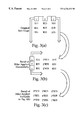
FIG. 4(c) shows an exemplary mask applied to attain the Green component of a super-pixel in a 4:1 scaled image.
As described above, for each scaled image super-pixel Xij, three components a Red component RXij, a Green component GXij and Blue component BXij need to be generated. The invention combines scaling and color interpolation to generate from an MxN CFA a ¼ size full color is often considered as consisting of intensity values for each of three color planes Red, Green and Blue. In the Bayer pattern CFA, the Red and Blue pixels are observable on alternative rows, but the Green pixels are observable on each and every row. Thus, in relation to either Red or Blue, twice as many Green pixels are present. The Green pixels are arranged in a staggered pattern and contain much of the important “luminance” information of the image that is critical for visual distinction of that image. For these reasons, the Green mask shown in FIG. 4(c) varies markedly from the Red and Blue masks of FIGS. 4(a) and 4(b), respectively.
FIG. 4(c) shows that there are only 8 products in the mask to obtain the Green component rather than 9. Also, the coefficients making up the mask products are not symmetric in the mask as they are with FIG. 4(a) and FIG. 4(b). Thus, a filter application in two dimensions such as that shown in FIGS. 3(a)-3(c) would find difficulty in producing the resultant mask in FIG. 4(c). The sum of the mask coefficients remains 16, but the weighting is concentrated in two pixels.
Referring back to FIG. 1, the scaling region for super-pixel X11has two centrally positioned Green pixels in the CFA, which are G23 and G32. All other Green pixels considered within the region are on an edge/corner. Thus, the central Green pixels, which represent the most likely to be essential luminance information in that scaling region, are assigned mask coefficients of 4. Referring to FIG. 4(c), the central Green pixels GM+1, N+2 and GM+2, N+1 are weighted by 4. Thus, the Green component GX11 of the super-pixel X11 may be represented as: [G12+G14+2*G21+4*G23+4*G32+2*G34+G41+G43]. Likewise, the Green component GX12 of the super-pixel X12 [G16+G18+2*G25+4*G27+4*G36+2*G38+G45+G47]/16.
Further, as noted above FIGS. 4(a) through 4(c) show masks for pixels of an image that is scaled down in size by 4. The quarter-size image scaling is often utilized in motion video applications such as videoconferencing. In other applications where a half-size or 2:1 scaling is needed, the masking procedure described above can be modified as follows. For a 2:1 scaled image every two rows and columns of pixels in the original unscaled CFA will be mapped or reduced to a single scaled image pixel. This case is shown in FIG. 2, where a 2:1 scaled image region is shown to be ½ the size of the scaling region in the original CFA. The size and number of products (i.e., the sampling criteria) may be modified or may be similar to that described above. If a fast hardware implementation of such dual-mode (2:1 and 4:1) scaling is desired, as is often the need for videoconferencing applications, utilizing a separate masking for each may be disadvantageous.
FIG. 5 is a diagram according to an embodiment of the invention.
FIG. 5 is a block diagram of internal image processing and compression components of an image capture device. A sensor 500 generates pixel components which are intensity values from some source. The m-bit pixel values generated by sensor 500 are sent to a capture interface 510. Sensor 500 in a digital camera context will typically sense either one of R, G, or B components for one “sense” of a location. Thus, the intensity value of each pixel is associated with only one of three color planes/(pixel). Capture interface 510 captures the image generated by the sensor and appends TAGs identifying color association for the individual pixels. The TAGs are two bits each, for example, 00, 01, 10 and 11 for R (Red), G (even-row Green), G (odd-row Green), B (Blue) pixels, respectively. The set of all such pixels for the entire image is the CFA.
It is typical in any sensor device that some of the pixel cells in the sensor plane may not respond to the lighting condition properly. As a result, the pixel values generated from these cell may be defective. These pixels are called “dead pixels.” The “pixel substitution” unit 515 replaces each dead pixel by the immediate previously valid pixel in the row.
A RAM table 516 consists of the row and column indices of the dead pixels, which are supplied by the sensor. This RAM table 516 helps to identify the location of dead pixels in relation to the captured image. Companding module 525 is a table look-up based converter to convert each original pixel of m-bit (labeled 10 b) intensity captured from the sensor to an n-bit intensity value, where m<n (typically m=10, n=8). A RAM table 526 accompanies companding module 525 and stores the entries of this exemplary sensor companding table. Thus, each pixel in the CFA will be an n-bit value representing one of the three color planes.
After companding, a scaling and color interpolation (SCI) unit 527 is used to scale down the image. If the original image size is M×N, a 2:1 scaling operation scales the image size down to M/2×N/2, while a 4:1 scaling operation scales the image size down to M/4×N/4 but with each scaled image pixel having all three color components. RAM 528 accompanies SCI unit 527 and is used for intermediate storage during the scaling/color interpolation operation.
According to various embodiments of the invention, scaling unit 527 is capable of efficiently simultaneously performing both scaling and color interpolation. As in one embodiment of the invention, the 4:1 scaling is achieved by applying a set of masks to sub-images (selected pixels in a particular color plane), one mask per color sub-image R, G and B. Since the masks are composed of coefficients (multipliers) of 1 and 4, the masks may be implemented by using a shift register which shifts left the intensity value for a given pixel.
In one embodiment of the invention, the mask products are summed together and then normalized to yield the scaled image pixel. The filter design using shift registers and buffers may be accompanied by an adder which adds the products obtained at every column or row into an accumulator. When all 9 (or 8 in the case of Green) products have been accumulated, the output of the accumulator may be passed to another shift register shifting out 4 bits to the right, or in effect, dividing by 16 which is the mask weighting for each of the three masks. Alternatively, as each row or column of pixels is being processed, the products resulting therefrom can be summed together and then normalized. For instance, the outputs of the three-tap filter can be passed to an adder to sum the products together. This sum can then be normalized by the sum of the filter taps, which is 4 (1+2+1). The division by four may be achieved by a shift right of 2 bits (again, using a shift register). Each normalized row or column result can be accumulated and when the filter is applied completely to the sampling region, the accumulated value may again be divided by normalized.
The original CFA may be scaled by a factor of 2 rather than 4 by SCI with 627. One skilled in the art will readily be able to modify the methodology described above to implement a 2:1 or N:1. With above implemented, scaled image data can more rapidly be generated and sent to the other image processing units shown in FIG. 6 and ultimately, will speed the delivery of image data over bus 560 and out of the image capture device. This is especially advantageous for the 4:1 scaling operation, which is used in videoconferencing where (frame rate maintenance) is important. The quality of the scaled image is also improved over traditional 4:1 scaling in that effective color interpolation is also simultaneously performed yielding scaled image data that is of full color. If the CFA has each pixel of n-bits, then each super-pixel in the scaled image will have 3*n bits associated with it, n bits for each color component. These color component values may be concatenated or transmitted separately as is desired. The scaled image data, obtained super-pixel by super-pixel may be passed to a compression unit 530 and on encoder 535 which compacts and encodes the scaled image data into manageable and transportable blocks. The compressed and encoded data is then packed together by a data packing unit 540 and then out to DMA controller 550 for transfer across BUS 560. Bus technology, addressing protocols and DMA controllers are well-known in the art of system design and can be readily modified/specialized to fit the desired application.
Each of the RAM tables 516, 526, 528, 532 and 534 can directly communicate with bus 560 so that their data can be loaded and then later, if desired, modified. Further, those RAM tables and other RAM tables may be used to store scaled image data as needed. Though the individual components (selectors, shifters, registers, and control address signals) of scaling unit 527 have not been detailed, one skilled in the art will readily be able to implement such a scaling device. The efficiency and ease of simultaneous and color interpolation yields the advantage of producing high quality, scaled down color image which will have edge features preserved in a better manner than with conventional scaling only techniques. Though the invention is described for an R, G and B CFA, it can be applied to any of the numerous CFA scheme such as MWY (Magenta, White and Yellow).
FIG. 6 is a system diagram of one embodiment of the invention.
Illustrated is a computer system 610 , which may be any general or special purpose computing or data processing machine such as a PC (personal computer), coupled to a camera 630. Camera 630 may be a digital camera, digital video camera, or any image capture device or imaging system, or combination thereof and is utilized to capture a sensor image of an scene 640. Essentially, captured images are processed by an image processing circuit 632 so that they can be efficiently stored in an image memory unit 634, which may be a ROM, RAM or other storage device such as a fixed disk. The image contained within image memory unit 634 that is destined for computer system 610 is enhanced in that the loss of image features due to conventional scaling and independent color interpolation is greatly mitigated by better preserving edge features. In most digital cameras that can perform still imaging, images are stored first and downloaded later. This allows the camera 630 to capture the next object/scene quickly without additional delay. However, in the case of digital video camera, especially one used for live videoconferencing, it is important that images not only be quickly captured, but quickly processed and transmitted out of camera 630. The invention in various embodiments is well-suited to providing fast throughput of color image data to other parts of the image processing circuit 632 so that the overall speed of transmitting image frames is increased over typical scaling techniques which do not color interpolate by their very nature.
Image scaling and color interpolation is carried out within the image processing circuit 632 in this embodiment of the invention. After the image is scaled/interpolated, it may also be compressed for transport. The decompression of the transmitted image data may be achieved using a processor 612 such as the Pentium® (a product of Intel Corporation) and a memory 611, such as RAM, which is used to store/load instruction addresses and result data. In an alternative embodiment, scaling/color interpolation may be achieved in software application running on computer system 610 rather than directly in hardware. The application(s) used to generate scaled image super-pixels after download from camera 630 may be an executable compiled from source code written in a language such as C++. The instructions of that executable file, which correspond with instructions necessary to scale the image, may be stored to a disk 618 or memory 611. It would be readily apparent to one of ordinary skill in the art to program a computing machine to scale and simultaneously color interpolate an image in accordance with the methodology described above. Further, the various embodiments of the invention may be implemented onto a video display adapter or graphics processing unit that provides scaling and color interpolation.
When an image, such as an image of a scene 640, is captured by camera 630, they are sent to the image processing circuit 632. Image processing circuit 632 consists of ICs and other components which execute, among other functions, the scaling down and simultaneous color interpolation of the captured image. The scaling/interpolation technique discussed herein, may utilize image memory unit to store the original CFA of the scene 640 captured by the camera 630. Further, this same memory unit can be used to store the scaled/interpolated image data. Once all pixels are scaled, processed and transferred to the computer system 610 for rendering, the camera 630 is free to capture the next image. The nature of the scaling technique in color interpolating allows for camera 630 to act as a motion camera that is color rather than gray scale even though it is not more complex than a pure gray scale type camera. When the user or application desires/requests a download of images, the scaled compressed images stored in the image memory unit are transferred from image memory unit 634 to the I/O port 617. I/O port 617 uses the bus-bridge hierarchy shown (I/O bus 615 to bridge 614 to system bus 613) to temporarily store the scaled and compressed image data into memory 611 or, optionally, disk 618.
The compressed images are decompressed on computer system 612 by suitable application software (or hardware), which may utilize processor 612 for its execution. The image data may then be rendered visually using a display adapter 616 into a rendered/scaled color image 650. The scaled color image is shown as being smaller in size than the original captured scene. This is desirable in many image applications where the original sensor capture size of a scene is not needed. In a videoconferencing application, the image data in its compressed and scaled form may be communicated over a network or communication system to another node or computer system in addition to or exclusive of computer system 610 so that a videoconferencing session may take place. Since scaling and color interpolation are already achieved on-camera in one embodiment of the invention, it may be possible to implement a co-mmunication port in camera 630 that allows the image data to be transported directly to the other node(s) in a videoconferencing session. Wherever a user of computer system 610 also desires to see his own scene on monitor 620, image data that is scaled and color interpolated may be sent both to computer system 610 and transported over a network to other nodes. Further, the various embodiments of the invention allow also for efficient software scaling to be implemented if desired. As discussed earlier, the scaled/interpolated color image will have more visually accurate edge features than typical in scaling operations due to the enhancement in the scaling process and the simultaneous nature of the color interpolation which is in effect an embedded process. The end result will be a higher quality rendered scaled image 650 that displayed onto monitor 620 or other nodes in a videoconferencing session as compared with even typical scaling methods which do not color interpolate, but leave that task to another device/process or stage of the imaging session.
The exemplary embodiments described herein are provided merely to illustrate the principles of the invention and should not be construed as limiting the scope of the invention. Rather, the principles of the invention may be applied to a wide range of systems to achieve the advantages described herein and to achieve other advantages or to satisfy other objectives as well.
Claims (19)
1. A method comprising:
defining a scaling region in a CFA (Color Filter Array) image; and
generating a super-pixel which is a downscaled version of said scaling region, said super-pixel being fully color interpolated, by applying a mask to a sub-image region of the CFA image, said sub-image region having pixels of all the same color plane and normalizing the result of applying said mask to form a color component of said super-pixel, said color component having the color associated with the sub-image region.
2. A method according to claim 1 wherein said CFA has each pixel associated with only one of three color planes.
3. A method according to claim 2 wherein said color planes are Red, Green and Blue.
4. A method according to claim 2 wherein said CFA is arranged in a Bayer pattern.
5. A method according to claim 1 wherein said down scaling is 4 to 1 down scaling.
6. A method according to claim 3 wherein full color interpolation for each super-pixel denotes that each super-pixel has components for all three said Red, Green and Blue color planes.
7. A method according to claim 1 wherein said mask is configured to favor a central portion of said sub-image region while maintaining the ability to represent edge features occurring elsewhere than said central portion.
8. A method according to claim 2 wherein said color planes are Magenta, White and Yellow.
9. An apparatus comprising:
a scaling and color interpolation unit configured to transform CFA (Color Filter Array) pixels, each associated with only one of multiple color components, into downscaled super-pixels, each super-pixel having all of said color components, by applying a mask to a sub-image region of the CFA pixels, said sub-image region having pixels of all the same color plane and normalizing the result of applying said mask to form a color component of a super-pixel, said color component having the color associated with the sub-image region.
10. An apparatus according to claim 9 comprising:
a memory coupled to said scaling and color interpolation unit, configured to store said super-pixel data.
11. An apparatus according to claim 9 comprising:
an image sensor coupled to said scaling and color interpolation unit, said sensor providing in a Bayer pattern data for said CFA.
12. An apparatus according to claim 9 wherein said scaling and color interpolation unit is incorporated into an imaging device.
13. An apparatus according to claim 12 wherein said imaging device is a digital camera.
14. An article of manufacture comprising a computer readable medium having instructions stored thereon which when executed by a processor cause:
a scaling region to be defined in a CFA (Color Filter Array) image; and
a super-pixel which is a downscaled version of said scaling region to be generated, said super-pixel being fully color interpolated, by applying a mask to a sub-image region of the CFA image, said sub-image region having pixels of all the same color plane and normalizing the result of applying said mask to form a color component of said super-pixel, said color component having the color associated with the sub-image region.
15. The article of manufacture of claim 14 wherein said CFA image has each pixel therein associated with only one of three color planes.
16. The article of manufacture of claim 15 wherein said color planes are Red, Green and Blue.
17. The article of manufacture of claim 16 wherein said CFA image is arranged in a Bayer pattern.
18. The article of manufacture of claim 17 wherein full color interpolation for each super-pixel denotes that each super-pixel has components for all three of said Red, Green, and Blue color planes.
19. The article of manufacture of claim 14 wherein the medium includes further instructions which when executed by the processor cause said mask to be configured to favor a central portion of said sub-image region while maintaining the ability to represent edge features occurring elsewhere than said central portion.
Priority Applications (8)
| Application Number | Priority Date | Filing Date | Title |
|---|---|---|---|
| US09/163,022 US6236433B1 (en) | 1998-09-29 | 1998-09-29 | Scaling algorithm for efficient color representation/recovery in video |
| TW088114036A TW456153B (en) | 1998-09-29 | 1999-08-17 | A new scaling algorithm for efficient color representation/recovery in video |
| JP2000573102A JP4261062B2 (en) | 1998-09-29 | 1999-09-16 | New scaling algorithm for efficient color representation / recovery in video |
| GB0106060A GB2357927B (en) | 1998-09-29 | 1999-09-16 | A new scaling algorithm for efficient color representation/recovery in video |
| DE19983600T DE19983600B4 (en) | 1998-09-29 | 1999-09-16 | A new scaling algorithm for efficient color reproduction / restoration in video |
| KR1020017003984A KR100569747B1 (en) | 1998-09-29 | 1999-09-16 | A new scaling algorithm for efficient color representation/recovery in video |
| PCT/US1999/021538 WO2000019728A1 (en) | 1998-09-29 | 1999-09-16 | A new scaling algorithm for efficient color representation/recovery in video |
| AU59276/99A AU5927699A (en) | 1998-09-29 | 1999-09-16 | A new scaling algorithm for efficient color representation/recovery in video |
Applications Claiming Priority (1)
| Application Number | Priority Date | Filing Date | Title |
|---|---|---|---|
| US09/163,022 US6236433B1 (en) | 1998-09-29 | 1998-09-29 | Scaling algorithm for efficient color representation/recovery in video |
Publications (1)
| Publication Number | Publication Date |
|---|---|
| US6236433B1 true US6236433B1 (en) | 2001-05-22 |
Family
ID=22588123
Family Applications (1)
| Application Number | Title | Priority Date | Filing Date |
|---|---|---|---|
| US09/163,022 Expired - Lifetime US6236433B1 (en) | 1998-09-29 | 1998-09-29 | Scaling algorithm for efficient color representation/recovery in video |
Country Status (8)
| Country | Link |
|---|---|
| US (1) | US6236433B1 (en) |
| JP (1) | JP4261062B2 (en) |
| KR (1) | KR100569747B1 (en) |
| AU (1) | AU5927699A (en) |
| DE (1) | DE19983600B4 (en) |
| GB (1) | GB2357927B (en) |
| TW (1) | TW456153B (en) |
| WO (1) | WO2000019728A1 (en) |
Cited By (71)
| Publication number | Priority date | Publication date | Assignee | Title |
|---|---|---|---|---|
| US20020044778A1 (en) * | 2000-09-06 | 2002-04-18 | Nikon Corporation | Image data processing apparatus and electronic camera |
| US6404918B1 (en) * | 1999-04-30 | 2002-06-11 | Hewlett-Packard Company | Image demosaicing method utilizing directional smoothing |
| US20020118746A1 (en) * | 2001-01-03 | 2002-08-29 | Kim Hyun Mun | Method of performing video encoding rate control using motion estimation |
| US20020161807A1 (en) * | 2001-03-30 | 2002-10-31 | Tinku Acharya | Two-dimensional pyramid filter architecture |
| WO2002089105A2 (en) * | 2001-05-02 | 2002-11-07 | Bitstream, Inc. | Methods, systems, and programming for producing and displaying subpixel-optimized images and digital content including such images |
| US20020184276A1 (en) * | 2001-03-30 | 2002-12-05 | Tinku Acharya | Two-dimensional pyramid filter architecture |
| US6507350B1 (en) * | 1999-12-29 | 2003-01-14 | Intel Corporation | Flat-panel display drive using sub-sampled YCBCR color signals |
| EP1308888A1 (en) * | 2001-11-06 | 2003-05-07 | STMicroelectronics S.r.l. | A method of processing digital images |
| US20030174077A1 (en) * | 2000-10-31 | 2003-09-18 | Tinku Acharya | Method of performing huffman decoding |
| US6625308B1 (en) | 1999-09-10 | 2003-09-23 | Intel Corporation | Fuzzy distinction based thresholding technique for image segmentation |
| US6628827B1 (en) | 1999-12-14 | 2003-09-30 | Intel Corporation | Method of upscaling a color image |
| US20030193580A1 (en) * | 2002-03-29 | 2003-10-16 | Satoru Okamoto | Digital camera and image pickup device |
| US6636167B1 (en) | 2000-10-31 | 2003-10-21 | Intel Corporation | Method of generating Huffman code length information |
| US20030202108A1 (en) * | 2002-04-24 | 2003-10-30 | Minolta Co., Ltd. | Image pick-up apparatus |
| US20030214594A1 (en) * | 2002-05-14 | 2003-11-20 | Sergey N. Bezryadin | Reconstruction of color components in digital image processing |
| US6658399B1 (en) | 1999-09-10 | 2003-12-02 | Intel Corporation | Fuzzy based thresholding technique for image segmentation |
| US6683996B1 (en) * | 1999-09-16 | 2004-01-27 | Silverbrook Research Pty Ltd | Method and apparatus for rotating Bayer images |
| US20040017952A1 (en) * | 1999-10-01 | 2004-01-29 | Tinku Acharya | Color video coding scheme |
| US20040032517A1 (en) * | 1999-05-25 | 2004-02-19 | Walmsley Simon Robert | Method and apparatus for bayer mosaic image conversion |
| US6697534B1 (en) | 1999-06-09 | 2004-02-24 | Intel Corporation | Method and apparatus for adaptively sharpening local image content of an image |
| US20040042551A1 (en) * | 2002-09-04 | 2004-03-04 | Tinku Acharya | Motion estimation |
| US20040047422A1 (en) * | 2002-09-04 | 2004-03-11 | Tinku Acharya | Motion estimation using logarithmic search |
| US20040057626A1 (en) * | 2002-09-23 | 2004-03-25 | Tinku Acharya | Motion estimation using a context adaptive search |
| US20040071350A1 (en) * | 2000-06-19 | 2004-04-15 | Tinku Acharya | Method of compressing an image |
| US6748118B1 (en) | 2000-02-18 | 2004-06-08 | Intel Corporation | Method of quantizing signal samples of an image during same |
| US6766286B2 (en) | 2001-03-28 | 2004-07-20 | Intel Corporation | Pyramid filter |
| US6775413B1 (en) | 2000-09-18 | 2004-08-10 | Intel Corporation | Techniques to implement one-dimensional compression |
| US20040169748A1 (en) * | 2003-02-28 | 2004-09-02 | Tinku Acharya | Sub-sampled infrared sensor for use in a digital image capture device |
| US20040169749A1 (en) * | 2003-02-28 | 2004-09-02 | Tinku Acharya | Four-color mosaic pattern for depth and image capture |
| US20040174441A1 (en) * | 2002-12-10 | 2004-09-09 | Stmicroelectronics S.R.I | Method and system for processing video signals, for example for displaying on a small sized color display, and corresponding computer program product |
| US20040174446A1 (en) * | 2003-02-28 | 2004-09-09 | Tinku Acharya | Four-color mosaic pattern for depth and image capture |
| US20040196389A1 (en) * | 2003-02-04 | 2004-10-07 | Yoshiaki Honda | Image pickup apparatus and method thereof |
| US20040201721A1 (en) * | 2001-08-23 | 2004-10-14 | Izhak Baharav | System and method for concurrently demosaicing and resizing raw data images |
| US6812963B1 (en) * | 1999-10-29 | 2004-11-02 | Hewlett-Packard Development Company, L.P. | Focus and exposure measurement in digital camera using charge binning |
| US20050185836A1 (en) * | 2004-02-24 | 2005-08-25 | Wei-Feng Huang | Image data processing in color spaces |
| US20050207676A1 (en) * | 2004-03-16 | 2005-09-22 | Wen-Kuo Lin | Method for decimating image data filtered by a bayer pattern color filter array |
| US6961472B1 (en) | 2000-02-18 | 2005-11-01 | Intel Corporation | Method of inverse quantized signal samples of an image during image decompression |
| US6992714B1 (en) * | 1999-05-31 | 2006-01-31 | Canon Kabushiki Kaisha | Image pickup apparatus having plural pixels arranged two-dimensionally, and selective addition of different pixel color signals to control spatial color arrangement |
| US7030917B2 (en) * | 1998-10-23 | 2006-04-18 | Hewlett-Packard Development Company, L.P. | Image demosaicing and enhancement system |
| US7046728B1 (en) | 2000-06-30 | 2006-05-16 | Intel Corporation | Method of video coding the movement of a human face from a sequence of images |
| US7053944B1 (en) | 1999-10-01 | 2006-05-30 | Intel Corporation | Method of using hue to interpolate color pixel signals |
| US20060170826A1 (en) * | 2005-01-13 | 2006-08-03 | Samsung Electronics Co., Ltd. | Digital video signal processing apparatus and method for adaptive Y/C separation |
| US7095164B1 (en) | 1999-05-25 | 2006-08-22 | Intel Corporation | Display screen |
| US7158178B1 (en) | 1999-12-14 | 2007-01-02 | Intel Corporation | Method of converting a sub-sampled color image |
| US20070035707A1 (en) * | 2005-06-20 | 2007-02-15 | Digital Display Innovations, Llc | Field sequential light source modulation for a digital display system |
| US20070035706A1 (en) * | 2005-06-20 | 2007-02-15 | Digital Display Innovations, Llc | Image and light source modulation for a digital display system |
| US20070046682A1 (en) * | 2005-08-31 | 2007-03-01 | Ati Technologies Inc. | Methods and apparatus for retrieving and combining samples of graphics information |
| US7219309B2 (en) | 2001-05-02 | 2007-05-15 | Bitstream Inc. | Innovations for the display of web pages |
| US20070133902A1 (en) * | 2005-12-13 | 2007-06-14 | Portalplayer, Inc. | Method and circuit for integrated de-mosaicing and downscaling preferably with edge adaptive interpolation and color correlation to reduce aliasing artifacts |
| US20070165116A1 (en) * | 2006-01-18 | 2007-07-19 | Szepo Robert Hung | Method and apparatus for adaptive and self-calibrated sensor green channel gain balancing |
| US20070230827A1 (en) * | 2004-04-29 | 2007-10-04 | Mikko Haukijarvi | Method and Apparatus for Downscaling a Digital Colour Matrix Image |
| US20070291138A1 (en) * | 2006-06-16 | 2007-12-20 | Raytheon Company | Imaging system and method with intelligent digital zooming |
| CN100366045C (en) * | 2005-01-11 | 2008-01-30 | 北京中星微电子有限公司 | Image conversion method capable of realizing zooming |
| US7379105B1 (en) * | 2002-06-18 | 2008-05-27 | Pixim, Inc. | Multi-standard video image capture device using a single CMOS image sensor |
| US7477781B1 (en) | 2002-10-10 | 2009-01-13 | Dalsa Corporation | Method and apparatus for adaptive pixel correction of multi-color matrix |
| WO2010081932A1 (en) * | 2009-01-19 | 2010-07-22 | Nokia Corporation | Method and apparatus for reducing size of image data |
| US20100194846A1 (en) * | 2009-01-30 | 2010-08-05 | Biggs Kent E | Equalization of video streams |
| USRE42045E1 (en) | 1999-10-21 | 2011-01-18 | Lg Electronics Inc. | Filtering control method for improving image quality of bi-linear interpolated image |
| US20110032269A1 (en) * | 2009-08-05 | 2011-02-10 | Rastislav Lukac | Automatically Resizing Demosaicked Full-Color Images Using Edge-Orientation Maps Formed In The Demosaicking Process |
| US20110229021A1 (en) * | 2010-03-17 | 2011-09-22 | Samsung Electronics Co. Ltd. | Apparatus and method for interpolating and rendering image on mobile devices |
| EP2211304A3 (en) * | 2009-01-20 | 2013-08-07 | SANYO Electric Co., Ltd. | Image processing apparatus |
| US8789939B2 (en) | 1998-11-09 | 2014-07-29 | Google Inc. | Print media cartridge with ink supply manifold |
| US8823823B2 (en) | 1997-07-15 | 2014-09-02 | Google Inc. | Portable imaging device with multi-core processor and orientation sensor |
| US8896724B2 (en) | 1997-07-15 | 2014-11-25 | Google Inc. | Camera system to facilitate a cascade of imaging effects |
| US8902340B2 (en) | 1997-07-12 | 2014-12-02 | Google Inc. | Multi-core image processor for portable device |
| US8902333B2 (en) | 1997-07-15 | 2014-12-02 | Google Inc. | Image processing method using sensed eye position |
| US8908075B2 (en) | 1997-07-15 | 2014-12-09 | Google Inc. | Image capture and processing integrated circuit for a camera |
| US8936196B2 (en) | 1997-07-15 | 2015-01-20 | Google Inc. | Camera unit incorporating program script scanner |
| US9055221B2 (en) | 1997-07-15 | 2015-06-09 | Google Inc. | Portable hand-held device for deblurring sensed images |
| US20150281506A1 (en) * | 2012-11-26 | 2015-10-01 | Nokia Corporation | Arrangement for image processing |
| US20160373653A1 (en) * | 2015-06-19 | 2016-12-22 | Samsung Electronics Co., Ltd. | Method for processing image and electronic device thereof |
Families Citing this family (5)
| Publication number | Priority date | Publication date | Assignee | Title |
|---|---|---|---|---|
| US7372484B2 (en) * | 2003-06-26 | 2008-05-13 | Micron Technology, Inc. | Method and apparatus for reducing effects of dark current and defective pixels in an imaging device |
| FI115587B (en) * | 2003-12-03 | 2005-05-31 | Nokia Corp | Procedures and devices for scaling down a digital matrix image |
| KR101237157B1 (en) | 2006-05-01 | 2013-02-25 | 엘지디스플레이 주식회사 | Method and apparatus for down sampling of Display |
| KR101406562B1 (en) | 2007-05-22 | 2014-06-12 | 엘지전자 주식회사 | Apparatus and method of Down_sampling |
| JP2016092664A (en) * | 2014-11-07 | 2016-05-23 | 株式会社ニコン | Digital camera, image output program and image recording program |
Citations (6)
| Publication number | Priority date | Publication date | Assignee | Title |
|---|---|---|---|---|
| US5053861A (en) * | 1989-07-24 | 1991-10-01 | Eastman Kodak Company | Compression method and apparatus for single-sensor color imaging systems |
| US5065229A (en) * | 1989-07-24 | 1991-11-12 | Eastman Kodak Company | Compression method and apparatus for single-sensor color imaging systems |
| US5418565A (en) * | 1994-02-15 | 1995-05-23 | Eastman Kodak Company | CFA compatible resolution reduction in a single sensor electronic camera |
| US5778106A (en) * | 1996-03-14 | 1998-07-07 | Polaroid Corporation | Electronic camera with reduced color artifacts |
| US5914749A (en) * | 1998-03-31 | 1999-06-22 | Intel Corporation | Magenta-white-yellow (MWY) color system for digital image sensor applications |
| US6046772A (en) * | 1997-07-24 | 2000-04-04 | Howell; Paul | Digital photography device and method |
Family Cites Families (13)
| Publication number | Priority date | Publication date | Assignee | Title |
|---|---|---|---|---|
| US5189526A (en) * | 1990-09-21 | 1993-02-23 | Eastman Kodak Company | Method and apparatus for performing image compression using discrete cosine transform |
| US5172227A (en) * | 1990-12-10 | 1992-12-15 | Eastman Kodak Company | Image compression with color interpolation for a single sensor image system |
| US5168375A (en) * | 1991-09-18 | 1992-12-01 | Polaroid Corporation | Image reconstruction by use of discrete cosine and related transforms |
| US5493335A (en) * | 1993-06-30 | 1996-02-20 | Eastman Kodak Company | Single sensor color camera with user selectable image record size |
| US5382976A (en) * | 1993-06-30 | 1995-01-17 | Eastman Kodak Company | Apparatus and method for adaptively interpolating a full color image utilizing luminance gradients |
| US5696848A (en) * | 1995-03-09 | 1997-12-09 | Eastman Kodak Company | System for creating a high resolution image from a sequence of lower resolution motion images |
| US5652621A (en) * | 1996-02-23 | 1997-07-29 | Eastman Kodak Company | Adaptive color plane interpolation in single sensor color electronic camera |
| US5631703A (en) * | 1996-05-29 | 1997-05-20 | Eastman Kodak Company | Particular pattern of pixels for a color filter array which is used to derive luminance and chrominance values |
| US5926218A (en) * | 1996-06-04 | 1999-07-20 | Eastman Kodak Company | Electronic camera with dual resolution sensors |
| KR200143568Y1 (en) * | 1996-08-30 | 1999-06-15 | 양재신 | The structure of a switch attached on a brake for an automobile |
| US5818975A (en) * | 1996-10-28 | 1998-10-06 | Eastman Kodak Company | Method and apparatus for area selective exposure adjustment |
| DE59709654D1 (en) * | 1996-10-31 | 2003-04-30 | Stuttgart Mikroelektronik | LIGHT-SENSITIVE SENSOR UNIT FOR AN ELECTRONIC CAMERA, WITH A SURFACE ARRANGEMENT OF IMAGE POINTS AND METHOD FOR READING THE IMAGE POINTS FOR COLOR SIGNAL PROCESSING |
| KR100216672B1 (en) * | 1996-12-30 | 1999-09-01 | 김영환 | Color filter array and its signal treatement circuit |
-
1998
- 1998-09-29 US US09/163,022 patent/US6236433B1/en not_active Expired - Lifetime
-
1999
- 1999-08-17 TW TW088114036A patent/TW456153B/en not_active IP Right Cessation
- 1999-09-16 DE DE19983600T patent/DE19983600B4/en not_active Expired - Fee Related
- 1999-09-16 KR KR1020017003984A patent/KR100569747B1/en not_active IP Right Cessation
- 1999-09-16 GB GB0106060A patent/GB2357927B/en not_active Expired - Fee Related
- 1999-09-16 WO PCT/US1999/021538 patent/WO2000019728A1/en not_active Application Discontinuation
- 1999-09-16 AU AU59276/99A patent/AU5927699A/en not_active Abandoned
- 1999-09-16 JP JP2000573102A patent/JP4261062B2/en not_active Expired - Fee Related
Patent Citations (6)
| Publication number | Priority date | Publication date | Assignee | Title |
|---|---|---|---|---|
| US5053861A (en) * | 1989-07-24 | 1991-10-01 | Eastman Kodak Company | Compression method and apparatus for single-sensor color imaging systems |
| US5065229A (en) * | 1989-07-24 | 1991-11-12 | Eastman Kodak Company | Compression method and apparatus for single-sensor color imaging systems |
| US5418565A (en) * | 1994-02-15 | 1995-05-23 | Eastman Kodak Company | CFA compatible resolution reduction in a single sensor electronic camera |
| US5778106A (en) * | 1996-03-14 | 1998-07-07 | Polaroid Corporation | Electronic camera with reduced color artifacts |
| US6046772A (en) * | 1997-07-24 | 2000-04-04 | Howell; Paul | Digital photography device and method |
| US5914749A (en) * | 1998-03-31 | 1999-06-22 | Intel Corporation | Magenta-white-yellow (MWY) color system for digital image sensor applications |
Cited By (169)
| Publication number | Priority date | Publication date | Assignee | Title |
|---|---|---|---|---|
| US8902340B2 (en) | 1997-07-12 | 2014-12-02 | Google Inc. | Multi-core image processor for portable device |
| US9338312B2 (en) | 1997-07-12 | 2016-05-10 | Google Inc. | Portable handheld device with multi-core image processor |
| US9544451B2 (en) | 1997-07-12 | 2017-01-10 | Google Inc. | Multi-core image processor for portable device |
| US8947592B2 (en) | 1997-07-12 | 2015-02-03 | Google Inc. | Handheld imaging device with image processor provided with multiple parallel processing units |
| US8947679B2 (en) | 1997-07-15 | 2015-02-03 | Google Inc. | Portable handheld device with multi-core microcoded image processor |
| US8902333B2 (en) | 1997-07-15 | 2014-12-02 | Google Inc. | Image processing method using sensed eye position |
| US8908075B2 (en) | 1997-07-15 | 2014-12-09 | Google Inc. | Image capture and processing integrated circuit for a camera |
| US8908069B2 (en) | 1997-07-15 | 2014-12-09 | Google Inc. | Handheld imaging device with quad-core image processor integrating image sensor interface |
| US8908051B2 (en) | 1997-07-15 | 2014-12-09 | Google Inc. | Handheld imaging device with system-on-chip microcontroller incorporating on shared wafer image processor and image sensor |
| US8902324B2 (en) | 1997-07-15 | 2014-12-02 | Google Inc. | Quad-core image processor for device with image display |
| US8953061B2 (en) | 1997-07-15 | 2015-02-10 | Google Inc. | Image capture device with linked multi-core processor and orientation sensor |
| US9237244B2 (en) | 1997-07-15 | 2016-01-12 | Google Inc. | Handheld digital camera device with orientation sensing and decoding capabilities |
| US8913182B2 (en) | 1997-07-15 | 2014-12-16 | Google Inc. | Portable hand-held device having networked quad core processor |
| US8902357B2 (en) | 1997-07-15 | 2014-12-02 | Google Inc. | Quad-core image processor |
| US8896720B2 (en) | 1997-07-15 | 2014-11-25 | Google Inc. | Hand held image capture device with multi-core processor for facial detection |
| US8896724B2 (en) | 1997-07-15 | 2014-11-25 | Google Inc. | Camera system to facilitate a cascade of imaging effects |
| US8866926B2 (en) | 1997-07-15 | 2014-10-21 | Google Inc. | Multi-core processor for hand-held, image capture device |
| US8836809B2 (en) | 1997-07-15 | 2014-09-16 | Google Inc. | Quad-core image processor for facial detection |
| US8823823B2 (en) | 1997-07-15 | 2014-09-02 | Google Inc. | Portable imaging device with multi-core processor and orientation sensor |
| US9055221B2 (en) | 1997-07-15 | 2015-06-09 | Google Inc. | Portable hand-held device for deblurring sensed images |
| US8928897B2 (en) | 1997-07-15 | 2015-01-06 | Google Inc. | Portable handheld device with multi-core image processor |
| US8934053B2 (en) | 1997-07-15 | 2015-01-13 | Google Inc. | Hand-held quad core processing apparatus |
| US8953060B2 (en) | 1997-07-15 | 2015-02-10 | Google Inc. | Hand held image capture device with multi-core processor and wireless interface to input device |
| US8937727B2 (en) | 1997-07-15 | 2015-01-20 | Google Inc. | Portable handheld device with multi-core image processor |
| US8936196B2 (en) | 1997-07-15 | 2015-01-20 | Google Inc. | Camera unit incorporating program script scanner |
| US8922670B2 (en) | 1997-07-15 | 2014-12-30 | Google Inc. | Portable hand-held device having stereoscopic image camera |
| US8913137B2 (en) | 1997-07-15 | 2014-12-16 | Google Inc. | Handheld imaging device with multi-core image processor integrating image sensor interface |
| US8953178B2 (en) | 1997-07-15 | 2015-02-10 | Google Inc. | Camera system with color display and processor for reed-solomon decoding |
| US8934027B2 (en) | 1997-07-15 | 2015-01-13 | Google Inc. | Portable device with image sensors and multi-core processor |
| US8913151B2 (en) | 1997-07-15 | 2014-12-16 | Google Inc. | Digital camera with quad core processor |
| US9219832B2 (en) | 1997-07-15 | 2015-12-22 | Google Inc. | Portable handheld device with multi-core image processor |
| US9060128B2 (en) | 1997-07-15 | 2015-06-16 | Google Inc. | Portable hand-held device for manipulating images |
| US9124736B2 (en) | 1997-07-15 | 2015-09-01 | Google Inc. | Portable hand-held device for displaying oriented images |
| US9124737B2 (en) | 1997-07-15 | 2015-09-01 | Google Inc. | Portable device with image sensor and quad-core processor for multi-point focus image capture |
| US9131083B2 (en) | 1997-07-15 | 2015-09-08 | Google Inc. | Portable imaging device with multi-core processor |
| US9137397B2 (en) | 1997-07-15 | 2015-09-15 | Google Inc. | Image sensing and printing device |
| US9584681B2 (en) | 1997-07-15 | 2017-02-28 | Google Inc. | Handheld imaging device incorporating multi-core image processor |
| US9560221B2 (en) | 1997-07-15 | 2017-01-31 | Google Inc. | Handheld imaging device with VLIW image processor |
| US8922791B2 (en) | 1997-07-15 | 2014-12-30 | Google Inc. | Camera system with color display and processor for Reed-Solomon decoding |
| US9137398B2 (en) | 1997-07-15 | 2015-09-15 | Google Inc. | Multi-core processor for portable device with dual image sensors |
| US9143636B2 (en) | 1997-07-15 | 2015-09-22 | Google Inc. | Portable device with dual image sensors and quad-core processor |
| US9143635B2 (en) | 1997-07-15 | 2015-09-22 | Google Inc. | Camera with linked parallel processor cores |
| US9148530B2 (en) | 1997-07-15 | 2015-09-29 | Google Inc. | Handheld imaging device with multi-core image processor integrating common bus interface and dedicated image sensor interface |
| US9432529B2 (en) | 1997-07-15 | 2016-08-30 | Google Inc. | Portable handheld device with multi-core microcoded image processor |
| US9197767B2 (en) | 1997-07-15 | 2015-11-24 | Google Inc. | Digital camera having image processor and printer |
| US9168761B2 (en) | 1997-07-15 | 2015-10-27 | Google Inc. | Disposable digital camera with printing assembly |
| US9179020B2 (en) | 1997-07-15 | 2015-11-03 | Google Inc. | Handheld imaging device with integrated chip incorporating on shared wafer image processor and central processor |
| US9185246B2 (en) | 1997-07-15 | 2015-11-10 | Google Inc. | Camera system comprising color display and processor for decoding data blocks in printed coding pattern |
| US9185247B2 (en) | 1997-07-15 | 2015-11-10 | Google Inc. | Central processor with multiple programmable processor units |
| US9191529B2 (en) | 1997-07-15 | 2015-11-17 | Google Inc | Quad-core camera processor |
| US9191530B2 (en) | 1997-07-15 | 2015-11-17 | Google Inc. | Portable hand-held device having quad core image processor |
| US7030917B2 (en) * | 1998-10-23 | 2006-04-18 | Hewlett-Packard Development Company, L.P. | Image demosaicing and enhancement system |
| US8789939B2 (en) | 1998-11-09 | 2014-07-29 | Google Inc. | Print media cartridge with ink supply manifold |
| US6404918B1 (en) * | 1999-04-30 | 2002-06-11 | Hewlett-Packard Company | Image demosaicing method utilizing directional smoothing |
| US6618503B2 (en) * | 1999-04-30 | 2003-09-09 | Hewlett-Packard Development Company, L.P. | Image demosaicing method utilizing directional smoothing |
| US20060216973A1 (en) * | 1999-05-25 | 2006-09-28 | Silverbrook Research Pty Ltd | Modular image processing device |
| US20040032517A1 (en) * | 1999-05-25 | 2004-02-19 | Walmsley Simon Robert | Method and apparatus for bayer mosaic image conversion |
| US7095164B1 (en) | 1999-05-25 | 2006-08-22 | Intel Corporation | Display screen |
| US8866923B2 (en) | 1999-05-25 | 2014-10-21 | Google Inc. | Modular camera and printer |
| US20100296116A1 (en) * | 1999-05-25 | 2010-11-25 | Silverbrook Research Pty Ltd | Multi-Module Device including a Printer Module |
| US7773263B2 (en) | 1999-05-25 | 2010-08-10 | Silverbrook Research Pty Ltd. | Multimedia pen with image processing module to convert captured images for printing by a printer module |
| US7061650B2 (en) * | 1999-05-25 | 2006-06-13 | Silverbrook Research Pty Ltd | Method and apparatus for bayer mosaic image conversion |
| US7372601B2 (en) | 1999-05-25 | 2008-05-13 | Silverbrook Ressearch Pty Ltd | Modular image processing device |
| US20080192305A1 (en) * | 1999-05-25 | 2008-08-14 | Silverbrook Research Pty Ltd | Multimedia pen with image processing module to convert captured images for printing by a printer module |
| US8045226B2 (en) | 1999-05-25 | 2011-10-25 | Silverbrook Research Pty Ltd | Multi-module device including a printer module |
| US6992714B1 (en) * | 1999-05-31 | 2006-01-31 | Canon Kabushiki Kaisha | Image pickup apparatus having plural pixels arranged two-dimensionally, and selective addition of different pixel color signals to control spatial color arrangement |
| US6697534B1 (en) | 1999-06-09 | 2004-02-24 | Intel Corporation | Method and apparatus for adaptively sharpening local image content of an image |
| US6625308B1 (en) | 1999-09-10 | 2003-09-23 | Intel Corporation | Fuzzy distinction based thresholding technique for image segmentation |
| US6658399B1 (en) | 1999-09-10 | 2003-12-02 | Intel Corporation | Fuzzy based thresholding technique for image segmentation |
| US6683996B1 (en) * | 1999-09-16 | 2004-01-27 | Silverbrook Research Pty Ltd | Method and apparatus for rotating Bayer images |
| US20040017952A1 (en) * | 1999-10-01 | 2004-01-29 | Tinku Acharya | Color video coding scheme |
| US7106910B2 (en) | 1999-10-01 | 2006-09-12 | Intel Corporation | Color video coding scheme |
| US7053944B1 (en) | 1999-10-01 | 2006-05-30 | Intel Corporation | Method of using hue to interpolate color pixel signals |
| USRE42747E1 (en) | 1999-10-21 | 2011-09-27 | Lg Electronics Inc. | Filtering control method for improving image quality of bi-linear interpolated image |
| USRE47341E1 (en) | 1999-10-21 | 2019-04-09 | Lg Electronics Inc. | Filtering control method for improving image quality of bi-linear interpolated image |
| USRE47337E1 (en) | 1999-10-21 | 2019-04-02 | Lg Electronics Inc. | Filtering control method for improving image quality of bi-linear interpolated image |
| USRE42045E1 (en) | 1999-10-21 | 2011-01-18 | Lg Electronics Inc. | Filtering control method for improving image quality of bi-linear interpolated image |
| USRE47310E1 (en) | 1999-10-21 | 2019-03-19 | Lg Electronics Inc. | Filtering control method for improving image quality of bi-linear interpolated image |
| USRE45859E1 (en) | 1999-10-21 | 2016-01-19 | Lg Electronics Inc. | Filtering control method for improving image quality of bi-linear interpolated image |
| USRE47291E1 (en) | 1999-10-21 | 2019-03-12 | Lg Electronics Inc. | Filtering control method for improving image quality of bi-linear interpolated image |
| USRE47238E1 (en) | 1999-10-21 | 2019-02-12 | Lg Electronics Inc. | Filtering control method for improving image quality of bi-linear interpolated image |
| USRE47274E1 (en) | 1999-10-21 | 2019-03-05 | Lg Electronics Inc. | Filtering control method for improving image quality of bi-linear interpolated image |
| US6812963B1 (en) * | 1999-10-29 | 2004-11-02 | Hewlett-Packard Development Company, L.P. | Focus and exposure measurement in digital camera using charge binning |
| US6628827B1 (en) | 1999-12-14 | 2003-09-30 | Intel Corporation | Method of upscaling a color image |
| US7158178B1 (en) | 1999-12-14 | 2007-01-02 | Intel Corporation | Method of converting a sub-sampled color image |
| US6507350B1 (en) * | 1999-12-29 | 2003-01-14 | Intel Corporation | Flat-panel display drive using sub-sampled YCBCR color signals |
| US6748118B1 (en) | 2000-02-18 | 2004-06-08 | Intel Corporation | Method of quantizing signal samples of an image during same |
| US6961472B1 (en) | 2000-02-18 | 2005-11-01 | Intel Corporation | Method of inverse quantized signal samples of an image during image decompression |
| US6738520B1 (en) | 2000-06-19 | 2004-05-18 | Intel Corporation | Method of compressing an image |
| US20040071350A1 (en) * | 2000-06-19 | 2004-04-15 | Tinku Acharya | Method of compressing an image |
| US7046728B1 (en) | 2000-06-30 | 2006-05-16 | Intel Corporation | Method of video coding the movement of a human face from a sequence of images |
| US20110216230A1 (en) * | 2000-09-06 | 2011-09-08 | Nikon Corporation | Image data processing apparatus and electronic camera |
| US20060132628A1 (en) * | 2000-09-06 | 2006-06-22 | Nikon Corporation | Image data processing apparatus and electronic camera |
| US8896722B2 (en) | 2000-09-06 | 2014-11-25 | Nikon Corporation | Image data processing apparatus and electronic camera |
| US20020044778A1 (en) * | 2000-09-06 | 2002-04-18 | Nikon Corporation | Image data processing apparatus and electronic camera |
| US6775413B1 (en) | 2000-09-18 | 2004-08-10 | Intel Corporation | Techniques to implement one-dimensional compression |
| US6982661B2 (en) | 2000-10-31 | 2006-01-03 | Intel Corporation | Method of performing huffman decoding |
| US20060087460A1 (en) * | 2000-10-31 | 2006-04-27 | Tinku Acharya | Method of generating Huffman code length information |
| US6987469B2 (en) | 2000-10-31 | 2006-01-17 | Intel Corporation | Method of generating Huffman code length information |
| US20030210164A1 (en) * | 2000-10-31 | 2003-11-13 | Tinku Acharya | Method of generating Huffman code length information |
| US6646577B2 (en) | 2000-10-31 | 2003-11-11 | Intel Corporation | Method of performing Huffman decoding |
| US7190287B2 (en) | 2000-10-31 | 2007-03-13 | Intel Corporation | Method of generating Huffman code length information |
| US20030174077A1 (en) * | 2000-10-31 | 2003-09-18 | Tinku Acharya | Method of performing huffman decoding |
| US6636167B1 (en) | 2000-10-31 | 2003-10-21 | Intel Corporation | Method of generating Huffman code length information |
| US20020118746A1 (en) * | 2001-01-03 | 2002-08-29 | Kim Hyun Mun | Method of performing video encoding rate control using motion estimation |
| US6766286B2 (en) | 2001-03-28 | 2004-07-20 | Intel Corporation | Pyramid filter |
| US6889237B2 (en) | 2001-03-30 | 2005-05-03 | Intel Corporation | Two-dimensional pyramid filter architecture |
| US20020161807A1 (en) * | 2001-03-30 | 2002-10-31 | Tinku Acharya | Two-dimensional pyramid filter architecture |
| US20020184276A1 (en) * | 2001-03-30 | 2002-12-05 | Tinku Acharya | Two-dimensional pyramid filter architecture |
| US20030095135A1 (en) * | 2001-05-02 | 2003-05-22 | Kaasila Sampo J. | Methods, systems, and programming for computer display of images, text, and/or digital content |
| WO2002089105A3 (en) * | 2001-05-02 | 2003-02-06 | Bitstream Inc | Methods, systems, and programming for producing and displaying subpixel-optimized images and digital content including such images |
| US7222306B2 (en) | 2001-05-02 | 2007-05-22 | Bitstream Inc. | Methods, systems, and programming for computer display of images, text, and/or digital content |
| US7219309B2 (en) | 2001-05-02 | 2007-05-15 | Bitstream Inc. | Innovations for the display of web pages |
| WO2002089105A2 (en) * | 2001-05-02 | 2002-11-07 | Bitstream, Inc. | Methods, systems, and programming for producing and displaying subpixel-optimized images and digital content including such images |
| US7287220B2 (en) | 2001-05-02 | 2007-10-23 | Bitstream Inc. | Methods and systems for displaying media in a scaled manner and/or orientation |
| US7737993B2 (en) | 2001-05-02 | 2010-06-15 | Kaasila Sampo J | Methods, systems, and programming for producing and displaying subpixel-optimized images and digital content including such images |
| US6989862B2 (en) | 2001-08-23 | 2006-01-24 | Agilent Technologies, Inc. | System and method for concurrently demosaicing and resizing raw data images |
| US20040201721A1 (en) * | 2001-08-23 | 2004-10-14 | Izhak Baharav | System and method for concurrently demosaicing and resizing raw data images |
| EP1308888A1 (en) * | 2001-11-06 | 2003-05-07 | STMicroelectronics S.r.l. | A method of processing digital images |
| US20030122937A1 (en) * | 2001-11-06 | 2003-07-03 | Mirko Guarnera | Method for processing digital CFA images, particularly for motion and still imaging |
| US20030193580A1 (en) * | 2002-03-29 | 2003-10-16 | Satoru Okamoto | Digital camera and image pickup device |
| US7333139B2 (en) * | 2002-03-29 | 2008-02-19 | Fujifilm Corporation | Digital camera having correction of center positions of color pixels generated by mixing of pixels of the same color |
| US20030202108A1 (en) * | 2002-04-24 | 2003-10-30 | Minolta Co., Ltd. | Image pick-up apparatus |
| US6933971B2 (en) | 2002-05-14 | 2005-08-23 | Kwe International, Inc. | Reconstruction of color components in digital image processing |
| US20030214594A1 (en) * | 2002-05-14 | 2003-11-20 | Sergey N. Bezryadin | Reconstruction of color components in digital image processing |
| US7379105B1 (en) * | 2002-06-18 | 2008-05-27 | Pixim, Inc. | Multi-standard video image capture device using a single CMOS image sensor |
| US20040042551A1 (en) * | 2002-09-04 | 2004-03-04 | Tinku Acharya | Motion estimation |
| US20040047422A1 (en) * | 2002-09-04 | 2004-03-11 | Tinku Acharya | Motion estimation using logarithmic search |
| US7266151B2 (en) | 2002-09-04 | 2007-09-04 | Intel Corporation | Method and system for performing motion estimation using logarithmic search |
| US20040057626A1 (en) * | 2002-09-23 | 2004-03-25 | Tinku Acharya | Motion estimation using a context adaptive search |
| US7477781B1 (en) | 2002-10-10 | 2009-01-13 | Dalsa Corporation | Method and apparatus for adaptive pixel correction of multi-color matrix |
| US20090263017A1 (en) * | 2002-10-10 | 2009-10-22 | Anthony Amir Tanbakuchi | Method for reconstruction of pixel color values |
| US7630003B2 (en) * | 2002-12-10 | 2009-12-08 | Stmicroelectronics S.R.L. | Method and system for processing video signals, for example for displaying on a small sized color display, and corresponding computer program product |
| US20040174441A1 (en) * | 2002-12-10 | 2004-09-09 | Stmicroelectronics S.R.I | Method and system for processing video signals, for example for displaying on a small sized color display, and corresponding computer program product |
| US20040196389A1 (en) * | 2003-02-04 | 2004-10-07 | Yoshiaki Honda | Image pickup apparatus and method thereof |
| US20040174446A1 (en) * | 2003-02-28 | 2004-09-09 | Tinku Acharya | Four-color mosaic pattern for depth and image capture |
| US20040169749A1 (en) * | 2003-02-28 | 2004-09-02 | Tinku Acharya | Four-color mosaic pattern for depth and image capture |
| US7274393B2 (en) | 2003-02-28 | 2007-09-25 | Intel Corporation | Four-color mosaic pattern for depth and image capture |
| US20040169748A1 (en) * | 2003-02-28 | 2004-09-02 | Tinku Acharya | Sub-sampled infrared sensor for use in a digital image capture device |
| US20050185836A1 (en) * | 2004-02-24 | 2005-08-25 | Wei-Feng Huang | Image data processing in color spaces |
| US20050207676A1 (en) * | 2004-03-16 | 2005-09-22 | Wen-Kuo Lin | Method for decimating image data filtered by a bayer pattern color filter array |
| US7760966B2 (en) * | 2004-04-29 | 2010-07-20 | Nokia Corporation | Method and apparatus for downscaling a digital colour matrix image |
| US20070230827A1 (en) * | 2004-04-29 | 2007-10-04 | Mikko Haukijarvi | Method and Apparatus for Downscaling a Digital Colour Matrix Image |
| EP2081148A1 (en) * | 2004-04-29 | 2009-07-22 | Nokia Corporation | Method and apparatus for downscaling a digital colour matrix image |
| CN100366045C (en) * | 2005-01-11 | 2008-01-30 | 北京中星微电子有限公司 | Image conversion method capable of realizing zooming |
| US7773157B2 (en) * | 2005-01-13 | 2010-08-10 | Samsung Electronics Co., Ltd. | Digital video signal processing apparatus and method for adaptive Y/C separation |
| US20060170826A1 (en) * | 2005-01-13 | 2006-08-03 | Samsung Electronics Co., Ltd. | Digital video signal processing apparatus and method for adaptive Y/C separation |
| US20070035706A1 (en) * | 2005-06-20 | 2007-02-15 | Digital Display Innovations, Llc | Image and light source modulation for a digital display system |
| US7364306B2 (en) | 2005-06-20 | 2008-04-29 | Digital Display Innovations, Llc | Field sequential light source modulation for a digital display system |
| US7404645B2 (en) | 2005-06-20 | 2008-07-29 | Digital Display Innovations, Llc | Image and light source modulation for a digital display system |
| US20070035707A1 (en) * | 2005-06-20 | 2007-02-15 | Digital Display Innovations, Llc | Field sequential light source modulation for a digital display system |
| US7551177B2 (en) * | 2005-08-31 | 2009-06-23 | Ati Technologies, Inc. | Methods and apparatus for retrieving and combining samples of graphics information |
| US20070046682A1 (en) * | 2005-08-31 | 2007-03-01 | Ati Technologies Inc. | Methods and apparatus for retrieving and combining samples of graphics information |
| US20070133902A1 (en) * | 2005-12-13 | 2007-06-14 | Portalplayer, Inc. | Method and circuit for integrated de-mosaicing and downscaling preferably with edge adaptive interpolation and color correlation to reduce aliasing artifacts |
| US8005297B2 (en) * | 2006-01-18 | 2011-08-23 | Qualcomm Incorporated | Method and apparatus for adaptive and self-calibrated sensor green channel gain balancing |
| US20070165116A1 (en) * | 2006-01-18 | 2007-07-19 | Szepo Robert Hung | Method and apparatus for adaptive and self-calibrated sensor green channel gain balancing |
| US20070291138A1 (en) * | 2006-06-16 | 2007-12-20 | Raytheon Company | Imaging system and method with intelligent digital zooming |
| US8054344B2 (en) * | 2006-06-16 | 2011-11-08 | Raytheon Company | Imaging system and method with intelligent digital zooming |
| US9042678B2 (en) | 2009-01-19 | 2015-05-26 | Nokia Corporation | Method and apparatus for reducing size of image data |
| WO2010081932A1 (en) * | 2009-01-19 | 2010-07-22 | Nokia Corporation | Method and apparatus for reducing size of image data |
| EP2211304A3 (en) * | 2009-01-20 | 2013-08-07 | SANYO Electric Co., Ltd. | Image processing apparatus |
| US20100194846A1 (en) * | 2009-01-30 | 2010-08-05 | Biggs Kent E | Equalization of video streams |
| US8284232B2 (en) * | 2009-01-30 | 2012-10-09 | Hewlett-Packard Development Company, L.P. | Equalization of video streams |
| US20110032269A1 (en) * | 2009-08-05 | 2011-02-10 | Rastislav Lukac | Automatically Resizing Demosaicked Full-Color Images Using Edge-Orientation Maps Formed In The Demosaicking Process |
| US20110229021A1 (en) * | 2010-03-17 | 2011-09-22 | Samsung Electronics Co. Ltd. | Apparatus and method for interpolating and rendering image on mobile devices |
| US8577185B2 (en) * | 2010-03-17 | 2013-11-05 | Samsung Electronics Co., Ltd. | Apparatus and method for interpolating and rendering image on mobile devices |
| US9681017B2 (en) * | 2012-11-26 | 2017-06-13 | Nokia Technologies Oy | Arrangement for image processing |
| US20150281506A1 (en) * | 2012-11-26 | 2015-10-01 | Nokia Corporation | Arrangement for image processing |
| US20160373653A1 (en) * | 2015-06-19 | 2016-12-22 | Samsung Electronics Co., Ltd. | Method for processing image and electronic device thereof |
Also Published As
| Publication number | Publication date |
|---|---|
| GB2357927A (en) | 2001-07-04 |
| GB0106060D0 (en) | 2001-05-02 |
| KR20010075439A (en) | 2001-08-09 |
| DE19983600T1 (en) | 2001-10-18 |
| KR100569747B1 (en) | 2006-04-11 |
| TW456153B (en) | 2001-09-21 |
| AU5927699A (en) | 2000-04-17 |
| WO2000019728A1 (en) | 2000-04-06 |
| GB2357927B (en) | 2002-11-27 |
| DE19983600B4 (en) | 2006-10-19 |
| JP4261062B2 (en) | 2009-04-30 |
| JP2002526999A (en) | 2002-08-20 |
Similar Documents
| Publication | Publication Date | Title |
|---|---|---|
| US6236433B1 (en) | Scaling algorithm for efficient color representation/recovery in video | |
| US6348929B1 (en) | Scaling algorithm and architecture for integer scaling in video | |
| US7397944B2 (en) | Processing pipeline of pixel data of a color image acquired by a digital sensor | |
| US7760966B2 (en) | Method and apparatus for downscaling a digital colour matrix image | |
| US6392699B1 (en) | Integrated color interpolation and color space conversion algorithm from 8-bit bayer pattern RGB color space to 12-bit YCrCb color space | |
| US6366694B1 (en) | Integrated color interpolation and color space conversion algorithm from 8-bit Bayer pattern RGB color space to 24-bit CIE XYZ color space | |
| US6366692B1 (en) | Median computation-based integrated color interpolation and color space conversion methodology from 8-bit bayer pattern RGB color space to 24-bit CIE XYZ color space | |
| CN101521751B (en) | Image capturing apparatus | |
| US8164662B2 (en) | Image-processing device for color image data and method for the image processing of color image data | |
| US20050024380A1 (en) | Method for reducing random access memory of IC in display devices | |
| JP2023025085A (en) | Camera image processing method and camera | |
| US20040061902A1 (en) | Color data image acquistion and processing | |
| US7595805B2 (en) | Techniques to facilitate use of small line buffers for processing of small or large images | |
| CN101227621A (en) | Method of performing interpolation for CFA in CMOS sensor and circuit thereof | |
| WO1999000763A1 (en) | A memory based vlsi architecture for image compression | |
| US6553153B1 (en) | Method and apparatus for reducing video data | |
| US6842191B1 (en) | Color image restoration with anti-alias | |
| US20070253626A1 (en) | Resizing Raw Image Data Before Storing The Data | |
| US20030122937A1 (en) | Method for processing digital CFA images, particularly for motion and still imaging | |
| US7551189B2 (en) | Method of and apparatus for digital image processing | |
| JP4997172B2 (en) | Image signal processing apparatus, method and program for image division processing | |
| CN113242413B (en) | Interpolation calculation method and system for anti-sawtooth RCCB filter array | |
| CN112584075B (en) | Image transmission method and system based on image resolution | |
| CN110049337B (en) | Compression processing method and system for capsule endoscope bayer image | |
| TWI532010B (en) | Color processing apparatus and method |
Legal Events
| Date | Code | Title | Description |
|---|---|---|---|
| AS | Assignment |
Owner name: INTEL CORPORATION, CALIFORNIA Free format text: ASSIGNMENT OF ASSIGNORS INTEREST;ASSIGNORS:ACHARYA, TINKU;METZ, WERNER;REEL/FRAME:009495/0352 Effective date: 19980921 |
|
| STCF | Information on status: patent grant |
Free format text: PATENTED CASE |
|
| CC | Certificate of correction | ||
| FPAY | Fee payment |
Year of fee payment: 4 |
|
| FPAY | Fee payment |
Year of fee payment: 8 |
|
| FPAY | Fee payment |
Year of fee payment: 12 |