US6234591B1 - Disk array subsystem for use in a data processing system - Google Patents
Disk array subsystem for use in a data processing system Download PDFInfo
- Publication number
- US6234591B1 US6234591B1 US08/547,604 US54760495A US6234591B1 US 6234591 B1 US6234591 B1 US 6234591B1 US 54760495 A US54760495 A US 54760495A US 6234591 B1 US6234591 B1 US 6234591B1
- Authority
- US
- United States
- Prior art keywords
- disk drive
- chassis
- wall
- shaped
- frame
- Prior art date
- Legal status (The legal status is an assumption and is not a legal conclusion. Google has not performed a legal analysis and makes no representation as to the accuracy of the status listed.)
- Expired - Lifetime
Links
Images


Classifications
-
- G—PHYSICS
- G11—INFORMATION STORAGE
- G11B—INFORMATION STORAGE BASED ON RELATIVE MOVEMENT BETWEEN RECORD CARRIER AND TRANSDUCER
- G11B33/00—Constructional parts, details or accessories not provided for in the other groups of this subclass
- G11B33/12—Disposition of constructional parts in the apparatus, e.g. of power supply, of modules
- G11B33/125—Disposition of constructional parts in the apparatus, e.g. of power supply, of modules the apparatus comprising a plurality of recording/reproducing devices, e.g. modular arrangements, arrays of disc drives
- G11B33/127—Mounting arrangements of constructional parts onto a chassis
- G11B33/128—Mounting arrangements of constructional parts onto a chassis of the plurality of recording/reproducing devices, e.g. disk drives, onto a chassis
-
- G—PHYSICS
- G06—COMPUTING; CALCULATING OR COUNTING
- G06F—ELECTRIC DIGITAL DATA PROCESSING
- G06F1/00—Details not covered by groups G06F3/00 - G06F13/00 and G06F21/00
- G06F1/16—Constructional details or arrangements
- G06F1/18—Packaging or power distribution
- G06F1/183—Internal mounting support structures, e.g. for printed circuit boards, internal connecting means
- G06F1/184—Mounting of motherboards
-
- G—PHYSICS
- G06—COMPUTING; CALCULATING OR COUNTING
- G06F—ELECTRIC DIGITAL DATA PROCESSING
- G06F1/00—Details not covered by groups G06F3/00 - G06F13/00 and G06F21/00
- G06F1/16—Constructional details or arrangements
- G06F1/18—Packaging or power distribution
- G06F1/183—Internal mounting support structures, e.g. for printed circuit boards, internal connecting means
- G06F1/187—Mounting of fixed and removable disk drives
-
- H—ELECTRICITY
- H05—ELECTRIC TECHNIQUES NOT OTHERWISE PROVIDED FOR
- H05K—PRINTED CIRCUITS; CASINGS OR CONSTRUCTIONAL DETAILS OF ELECTRIC APPARATUS; MANUFACTURE OF ASSEMBLAGES OF ELECTRICAL COMPONENTS
- H05K7/00—Constructional details common to different types of electric apparatus
- H05K7/20—Modifications to facilitate cooling, ventilating, or heating
- H05K7/20536—Modifications to facilitate cooling, ventilating, or heating for racks or cabinets of standardised dimensions, e.g. electronic racks for aircraft or telecommunication equipment
- H05K7/20554—Forced ventilation of a gaseous coolant
- H05K7/20572—Forced ventilation of a gaseous coolant within cabinets for removing heat from sub-racks, e.g. plenum
Definitions
- the present invention relates generally to data processing system and, more particularly, to a new and novel disk array subsystem for use in a data processing system.
- CPU's are capable of processing data much more quickly than mass storage devices are capable of delivering data. Consequently, a CPU often loses time, standing idle, while waiting for needed data to be transferred thereto from a mass storage device. As can readily be appreciated, this inefficiency frequently results in a waste of the tremendous horsepower of the CPU, which does not achieve maximum performance.
- subsystems comprising disk arrays, i.e., groups of small, independent disk drive modules used to store large quantities of data, have been developed and found to possess many advantages over a single large disk drive.
- the individual modules of a disk array typically take up very little space and typically use less power and cost less than a single large disk drive, yet, when grouped together in an array, provide the same data storage capacity as single large disk drive.
- the small disks of an array retrieve data more quickly than does a single large disk drive because, with a small disk drive, there is less distance for the actuator to travel and less data per individual disk to search through.
- the greatest advantage to small disk drives is the boost they give to I/O performance when configured as a disk array subsystem.
- multiple drives process concurrent data retrieval/storage requests.
- the disks operate simultaneously. While one disk drive is retrieving/storing data, another can be sending data to the CPU. With several disks performing overlapped seeks, data can be retrieved and delivered more rapidly to the CPU. The CPU spends less time idle, so overall system performance improves substantially.
- disk array subsystems examples include the Data General Corp. High Availability Disk Array (H.A.D.A.) subsystem and the Data General Corp. Combined Storage Subsystem 2 (CSS2) subsystem. Both of these disk array subsystems use 5.25 inch disk drives.
- a disk array subsystem adapted for use in a data processing system comprises a chassis, a backplane fixedly mounted inside said chassis, disk drive module guide plate means, said disk drive module guide plate means including a first guide plate having a plurality of parallel slotted channels, said first guide plate being fixedly mounted inside said chassis, a plurality of disk drive modules slidably and removably mounted on said first guide plate, each disk drive module including an elongated T-bar slidably mounted in one of said parallel slotted channels, said disk drive module guide plate means serving to support said disk drive modules and to place the disk drive modules mounted thereon in approximate alignment with said backplane for electrical connection therewith, controller means for controlling the operations of said disk drive modules, and power supply means for powering said disk drive modules.
- each disk drive module and its associated slotted channel on the first guide plate include a pawl and detente combination for securing the disk drive module in place on its associated slotted channel.
- each disk drive module contains a 3.5 inch disk drive, and twenty such disk drive modules are mounted in the chassis, the subsystem having an outer length of 19 inches and an outer width of 14 inches.
- the chassis is a generally rectangular box-like structure, and air circulating means are provided at the rear end thereof to move air longitudinally from the front end through the back end.
- the disk drive module includes a frame and a regulator card having an edge connector and wherein the regulator card is movably mounted on the frame so as to facilitate mating the edge connector with an associated connector on the backplane.
- FIG. 1 is a perspective view of one embodiment of a disk array subsystem constructed according to the teachings of the present invention
- FIG. 2 is a simplified partially exploded front perspective view of the disk array subsystem shown in FIG. 2;
- FIG. 3 is a top view of one of the first disk drive module guide plates shown in FIG. 2;
- FIG. 4 is a bottom view of the first disk drive module guide plate shown in FIG. 3;
- FIG. 5 is a fragmentary top view of the first disk drive module guide plate shown in FIG. 3;
- FIG. 6 is a fragmentary bottom view of the first disk drive module guide plate shown in FIG. 3;
- FIG. 7 is a fragmentary bottom perspective view of one of the second disk drive module guide plates shown in FIG. 2;
- FIG. 8 is a front view of the backplane shown in FIG. 2;
- FIG. 9 is a right side view of one of the disk drive modules shown in FIG. 1;
- FIG. 10 is a left side view of the disk drive module shown in FIG. 9;
- FIG. 11 is a front view of the disk drive module shown in FIG. 9;
- FIG. 12 is a rear view of the disk drive module shown in FIG. 9;
- FIG. 13 is a right side view of the frame of the disk drive module shown in FIG. 9;
- FIG. 14 is a perspective view, taken from the left, of the frame shown in FIG. 13;
- FIG. 15 is a fragmentary perspective view, taken from the rear, of the frame shown in FIG. 13;
- FIG. 16 is a section view showing the disk drive module of FIG. 9 mounted and secured in place on the first disk drive module guide plate of FIG. 3;
- FIG. 17 is a front view of an empty or filler disk drive module constructed according to the teachings of the present invention.
- FIGS. 18 ( a ) and 18 ( b ) are right and left side views, respectively, of the filler disk drive module shown in FIG. 17;
- FIG. 19 is a perspective view of a second embodiment of a disk array subsystem constructed according to the teachings of the present invention.
- FIG. 20 is an exploded perspective view of the disk array subsystem shown in FIG. 19 with the fan pack and the components of the chassis removed.
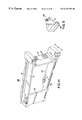
- FIGS. 1 and 2 there is shown of one embodiment of a disk array subsystem adapted for use in a data processing system, the disk array subsystem being constructed according to the teachings of the present invention and being represented generally by reference numeral 11 . Portions of subsystem 11 not pertinent to the invention are not shown.
- Subsystem 11 comprises a generally rectangular hollow chassis 13 which is preferably made from metal or any other material having sufficient strength. Chassis 13 may be integrally formed or assembled from individual parts. Chassis 13 includes a top wall 15 , a bottom wall 17 , a pair of side walls 19 - 1 and 19 - 2 , an open front end and an open rear end.
- a generally rectangular open front panel 21 is fixedly mounted by any suitable means such as screws (not shown) over the front end of chassis 13 .
- Panel 21 has a large rectangular opening 21 - 1 and a plurality of holes 21 - 2 .
- a fan pack 23 is removably mounted over the rear end of chassis 13 .
- Fan pack 23 includes a set of six exhaust fans 25 - 1 through 25 - 6 which are used to cool the contents of chassis 13 by drawing air in a generally unidirectional path through holes in the front end of chassis 13 , such as holes 21 - 2 across the length thereof, and then out the rear end.
- chassis 13 Disposed within chassis 13 are three power supplies 27 - 1 through 27 - 3 , a pair of controller boards 29 - 1 and 29 - 2 , a backplane 31 , and a set of twenty identical disk drive modules 33 - 1 through 33 - 20 .
- Power supplies 27 - 1 through 21 - 3 are electrically connected to the rear surface of backplane 31 and provide power to subsystem 11 .
- Controller boards 29 - 1 and 29 - 2 are electrically connected to the rear surface of backplane 31 and control the operations of subsystem 11 .
- the specifics of how power supplies 27 supply power to the subsystem and how controller boards 29 control operations of the subsystem are not a part of this invention.
- Power supplies 27 - 1 through 27 - 3 and controller boards 29 - 1 and 29 - 2 are slidably and removably mounted inside chassis 13 on supporting brackets (not shown).
- Disk drive modules 33 - 1 through 33 - 20 are slidably and removably mounted in chassis 13 through opening 21 - 1 in two rows with ten modules 33 in each row.
- the structure for mounting modules 33 in chassis 13 includes four first disk drive module guide plates 35 - 1 through 35 - 4 and two second disk drive module guide plates 37 - 1 and 37 - 2 , all of which are horizontally disposed in chassis 13 .
- Guide plates 35 - 1 and 35 - 2 are fixedly mounted on bottom wall 17 by screws (not shown) and guide plate 37 - 1 is fixedly mounted on top wall 15 by screws (not shown).
- Guide plate 37 - 2 is fixedly mounted on side walls 19 by screws (not shown) and guide plates 35 - 3 and 35 - 4 are fixedly mounted on top of second guide plate 37 - 2 by screws (not shown).
- Each disk drive module 33 is slidably mounted on a first guide plate 35 and a second guide plate 37 .
- guide plates 35 and 37 also serve to place disk drive modules 33 in approximate alignment with backplane 31 for electrical connection therewith.
- First disk drive module guide plate 35 - 1 is shown in greater detail in FIGS. 3 through 7.
- plate 35 - 1 is a unitary generally rectangularly molded structure made of plastic and shaped to define five longitudinally disposed parallel channels 39 - 1 through 39 - 5 .
- Each channel 39 includes a top wall having two sections 40 - 1 and 40 - 2 , each of which is slotted, and a bottom wall having three sections 41 - 1 , 41 - 2 and 41 - 3 .
- the bottom side of section 40 - 1 of the top wall is shaped to define a pawl 44 .
- First disk drive module guide plates 35 - 2 through 35 - 4 are identical in construction to first disk module drive guide plate 35 - 1 .
- Second disk drive module guide plate 37 - 1 is a generally rectangular plate having ten longitudinally disposed parallel grooves 43 . Three such grooves 43 are shown in FIG. 7 and are labelled 43 - 1 through 43 - 3 .
- FIG. 8 there is shown a front view of backplane 31 .
- a plurality of electrical connectors 45 - 1 through 45 - 20 are disposed on the front side of backplane 31 , each for use with one of the disk drive modules 33 .
- a plurality of holes 47 are provided on backplane 31 through which air drawn by fans 25 may pass to cool the inside of chassis 13 .
- Backplane 31 is fixedly mounted within chassis 13 by means of a supporting bracket (not shown).
- module 33 - 1 includes an elongated, generally rectangular, unitary frame 49 (see also FIGS. 13 through 15 wherein frame 49 is shown separately).
- Frame 49 includes a top wall 51 , a bottom wall 53 , a front wall 55 , a rear wall 57 , and a side wall 59 .
- Top wall 51 includes a longitudinally extending fin 61 and bottom wall 53 includes a longitudinally extending T-bar 63 .
- T-bar 63 is slidably inserted into a channel 39 on first disk drive module guide plate 35
- fin 61 is slidably inserted into a corresponding groove 43 on second disk drive module guide plate 37 .
- T-bar 63 , fin 61 , channel 39 , and groove 43 are chamfered as shown to facilitate insertion.
- T-bar 63 is shaped to include a detente 65 which slides over pawl 44 once module 33 has been fully inserted into its appropriate channel 39 in first disk drive module guide plate (see FIG. 16 ). Removal of module 33 from channel 39 once it has been secured thereto with the aforementioned pawl and detente combination is accomplished by pulling module 33 with sufficient force to cause detente 65 to slide back over pawl 44 in the reverse direction.
- a handle 66 is fixedly mounted on front wall 55 of frame 49 with an adhesive (not shown) to facilitate insertion and removal of drive module 33 into and out of chassis 13 .
- frame 49 has a top surface length L t of approximately 290 mm, a bottom surface length L b of approximately 294 mm, a height h of approximately 135 mm, and a width z of approximately 41.8 mm.
- plate 35 has a length L of approximately 198 mm and a width W of approximately 191 mm.
- Each channel 39 has a width x of approximately 16 mm with adjacent channels 39 being separated by a distance d of approximately 24 mm.
- Ribbon cable 71 electrically connects disk drive 67 to regulator card 69 .
- the rear edge of regulator card 69 includes an edge connector 73 which extends rearwardly a short distance beyond rear wall 57 and is mateable with an electrical connector 45 on the front side on backplane 31 .
- regulator card 69 is mounted on frame 49 so that it can move in three directions. This is accomplished by mounting regulator card 69 on bifurcated squeezable snaps 75 through oversized holes 76 - 1 through 76 - 4 . As can be seen, because holes 76 are oversized relative to snaps 75 , regulator card 69 can move in the plane of the card.
- Each snap 75 includes a tab 77 which serves to limit upward movement of card 69 relative to frame 49 .
- the distance from the bottom of tabs 77 to side wall 59 is greater than the thickness of card 69 . Consequently, card 69 can also move in a direction perpendicular to side wall 59 .
- a plurality of holes 81 are provided in front wall 55 of frame 49 to permit air drawn by fan pack 23 to pass therethrough into chassis 13 .
- FIGS. 17, 18 ( a ) and 18 ( b ) there is shown an empty or filler disk drive module 83 constructed according to the teachings of the present invention.
- Filler module 83 which may be inserted into chassis 13 in place of a disk drive module 33 should less than the maximal number of disk drives be needed for operation of subsystem 11 , consists of an elongated frame 85 and a handle 87 .
- Frame 85 is identical in construction, shape and size to elongated frame 49 of disk drive module 33 .
- Handle 87 which extends over the entire width of front wall 55 , is fixedly mounted on the front end of frame 85 with a suitable adhesive (not shown).
- subsystem 11 preferably complies with NEMA standards by having an outer length L o of 19 inches and an outer width W o of 14 inches.
- FIG. 19 there is shown a second embodiment of a disk array subsystem constructed according to the teachings of the present invention, the subsystem taking the form of a stand-alone tower unit 101 .
- FIG. 20 An exploded view of tower unit 101 without the various electronic components and fan pack is shown in FIG. 20 and includes chassis 13 , front panel 102 , a top panel 103 , a bottom panel 105 , a pair of side panels 107 - 1 and 107 - 2 , and a frame 109 on casters.
Abstract
A disk array subsystem for use in a data processing system. In one embodiment, the disk array subsystem comprises a generally rectangular chassis having a top wall, a bottom wall, a pair of side walls, an open front end and an open rear end. A fan pack is removably mounted over the open rear of the chassis to cool the contents thereof by drawing air into the chassis through the open front end and out of the chassis through the open rear end. Disposed within the chassis are three power supplies, a pair of controller boards, a backplane, and a set of twenty disk drive modules. A mounting structure comprising four first disk drive module guide plates and a pair of second disk drive module guides is fixedly mounted within the chassis for removably mounting the disk drive modules in the chassis through the open front end and for placing the disk drive modules in approximate alignment with the backplane for electrical connection therewith. Each first guide plate is shaped to include five parallel slotted channels, and each second disk drive module guide plate is shaped to include ten parallel grooves. Each of the twenty disk drive modules includes an elongated frame having a longitudinally extending T-bar adapted for slidable insertion into one of the slotted channels and a longitudinally extending fin adapted for slidable insertion into one of the grooves. The T-bar is shaped to include a detente, and the slotted channel is shaped to include a pawl, the detente and the pawl being interengageable so as to permit the disk drive module to be secured in place on its associated slotted channel.
Description
This is a continuation of application(s) Ser. No. 08/191,039 filed on Feb. 3, 1994, now U.S. Pat. No. 5,990,723 which is a divisional of Ser. No. 08/080,310 filed Jun. 24, 1993, now U.S. Pat. No. 5,343,357 which is a divisional of Ser. No. 07/935,110 filed Aug. 26, 1992 now U.S. Pat. No. 5,247,427.
The present invention relates generally to data processing system and, more particularly, to a new and novel disk array subsystem for use in a data processing system.
One well known problem associated with data processing systems is computer system throughput, namely, the relatively slow rate at which mass storage devices are capable of accessing data.
Generally speaking, CPU's are capable of processing data much more quickly than mass storage devices are capable of delivering data. Consequently, a CPU often loses time, standing idle, while waiting for needed data to be transferred thereto from a mass storage device. As can readily be appreciated, this inefficiency frequently results in a waste of the tremendous horsepower of the CPU, which does not achieve maximum performance.
In the past, approaches utilizing disk caches and data base segmenting were developed to minimize this problem. However, none of these approaches met all of the requirements of a high-transaction processing environment.
Recently, subsystems comprising disk arrays, i.e., groups of small, independent disk drive modules used to store large quantities of data, have been developed and found to possess many advantages over a single large disk drive. For example, the individual modules of a disk array typically take up very little space and typically use less power and cost less than a single large disk drive, yet, when grouped together in an array, provide the same data storage capacity as single large disk drive. In addition, the small disks of an array retrieve data more quickly than does a single large disk drive because, with a small disk drive, there is less distance for the actuator to travel and less data per individual disk to search through. The greatest advantage to small disk drives, however, is the boost they give to I/O performance when configured as a disk array subsystem.
In a disk array configuration, multiple drives process concurrent data retrieval/storage requests. Supported by a software “device driver” and individual controllers, the disks operate simultaneously. While one disk drive is retrieving/storing data, another can be sending data to the CPU. With several disks performing overlapped seeks, data can be retrieved and delivered more rapidly to the CPU. The CPU spends less time idle, so overall system performance improves substantially.
Examples of known disk array subsystems are the Data General Corp. High Availability Disk Array (H.A.D.A.) subsystem and the Data General Corp. Combined Storage Subsystem 2 (CSS2) subsystem. Both of these disk array subsystems use 5.25 inch disk drives.
Accordingly, it is an object of the present invention to provide a new and novel disk array subsystem.
It is another object of the present invention to provide a new and novel disk drive module for use in a disk array subsystem.
It is still another object of the present invention to provide a disk array subsystem having a plurality of disk drive modules and wherein the individual disk drive modules can be easily replaced when necessary.
It is still yet another object of the present invention to provide a disk array subsystem as described above whose size and shape conform to industry standards for purposes of modularity and, yet, which has the capacity to include a maximal number of disk drive modules.
It Is a further object of the present invention to provide a disk array subsystem as described above which uses disk drive modules having 3.5 inch disk drives.
It is still a further object of the present invention to provide a disk array subsystem as described above which includes a chassis and a new and novel arrangement for slidably and removably mounting the disk drive modules in the chassis.
It is still yet a further object of the present invention to provide a disk array subsystem as described above which includes a new and novel arrangement for securing the disk drive modules in place within the chassis of the subsystem.
It is another object of the present invention to provide a disk array subsystem as described above which includes a new and novel arrangement for cooling the components contained in the disk array subsystem.
A disk array subsystem adapted for use in a data processing system according to this invention comprises a chassis, a backplane fixedly mounted inside said chassis, disk drive module guide plate means, said disk drive module guide plate means including a first guide plate having a plurality of parallel slotted channels, said first guide plate being fixedly mounted inside said chassis, a plurality of disk drive modules slidably and removably mounted on said first guide plate, each disk drive module including an elongated T-bar slidably mounted in one of said parallel slotted channels, said disk drive module guide plate means serving to support said disk drive modules and to place the disk drive modules mounted thereon in approximate alignment with said backplane for electrical connection therewith, controller means for controlling the operations of said disk drive modules, and power supply means for powering said disk drive modules.
According to one feature of the invention, each disk drive module and its associated slotted channel on the first guide plate include a pawl and detente combination for securing the disk drive module in place on its associated slotted channel.
According to another feature of the invention, each disk drive module contains a 3.5 inch disk drive, and twenty such disk drive modules are mounted in the chassis, the subsystem having an outer length of 19 inches and an outer width of 14 inches.
According to still another feature of the invention, the chassis is a generally rectangular box-like structure, and air circulating means are provided at the rear end thereof to move air longitudinally from the front end through the back end.
According to still yet another feature of the invention, the disk drive module includes a frame and a regulator card having an edge connector and wherein the regulator card is movably mounted on the frame so as to facilitate mating the edge connector with an associated connector on the backplane.
Various other objects, as well as features and advantages, of the present invention will be set forth in part in the description which follows, and in part will be obvious from the description or may be learned by practice of the invention. In the description, reference is made to the accompanying drawings which form a part thereof and in which is shown by way of illustration specific embodiments for practicing the invention. These embodiments will be described in sufficient detail to enable those skilled in the art to practice the invention, and it is to be understood that other embodiments may be utilized and that structural changes may be made without departing from the scope of the invention. The following detailed description is, therefore, not to be taken in a limiting sense, and the scope of the present invention is best defined by the appended claims.
The accompanying drawings, which are hereby incorporated into and constitute a part of this specification, illustrate various embodiments of the invention and, together with the description, serve to explain the principles of the invention. In the drawings wherein like reference numerals represent like parts:
FIG. 1 is a perspective view of one embodiment of a disk array subsystem constructed according to the teachings of the present invention;
FIG. 2 is a simplified partially exploded front perspective view of the disk array subsystem shown in FIG. 2;
FIG. 3 is a top view of one of the first disk drive module guide plates shown in FIG. 2;
FIG. 4 is a bottom view of the first disk drive module guide plate shown in FIG. 3;
FIG. 5 is a fragmentary top view of the first disk drive module guide plate shown in FIG. 3;
FIG. 6 is a fragmentary bottom view of the first disk drive module guide plate shown in FIG. 3;
FIG. 7 is a fragmentary bottom perspective view of one of the second disk drive module guide plates shown in FIG. 2;
FIG. 8 is a front view of the backplane shown in FIG. 2;
FIG. 9 is a right side view of one of the disk drive modules shown in FIG. 1;
FIG. 10 is a left side view of the disk drive module shown in FIG. 9;
FIG. 11 is a front view of the disk drive module shown in FIG. 9;
FIG. 12 is a rear view of the disk drive module shown in FIG. 9;
FIG. 13 is a right side view of the frame of the disk drive module shown in FIG. 9;
FIG. 14 is a perspective view, taken from the left, of the frame shown in FIG. 13;
FIG. 15 is a fragmentary perspective view, taken from the rear, of the frame shown in FIG. 13;
FIG. 16 is a section view showing the disk drive module of FIG. 9 mounted and secured in place on the first disk drive module guide plate of FIG. 3;
FIG. 17 is a front view of an empty or filler disk drive module constructed according to the teachings of the present invention;
FIGS. 18(a) and 18(b) are right and left side views, respectively, of the filler disk drive module shown in FIG. 17;
FIG. 19 is a perspective view of a second embodiment of a disk array subsystem constructed according to the teachings of the present invention; and
FIG. 20 is an exploded perspective view of the disk array subsystem shown in FIG. 19 with the fan pack and the components of the chassis removed.
Referring now to FIGS. 1 and 2, there is shown of one embodiment of a disk array subsystem adapted for use in a data processing system, the disk array subsystem being constructed according to the teachings of the present invention and being represented generally by reference numeral 11. Portions of subsystem 11 not pertinent to the invention are not shown.
Subsystem 11 comprises a generally rectangular hollow chassis 13 which is preferably made from metal or any other material having sufficient strength. Chassis 13 may be integrally formed or assembled from individual parts. Chassis 13 includes a top wall 15, a bottom wall 17, a pair of side walls 19-1 and 19-2, an open front end and an open rear end.
A generally rectangular open front panel 21 is fixedly mounted by any suitable means such as screws (not shown) over the front end of chassis 13. Panel 21 has a large rectangular opening 21-1 and a plurality of holes 21-2. A fan pack 23 is removably mounted over the rear end of chassis 13. Fan pack 23 includes a set of six exhaust fans 25-1 through 25-6 which are used to cool the contents of chassis 13 by drawing air in a generally unidirectional path through holes in the front end of chassis 13, such as holes 21-2 across the length thereof, and then out the rear end.
Disposed within chassis 13 are three power supplies 27-1 through 27-3, a pair of controller boards 29-1 and 29-2, a backplane 31, and a set of twenty identical disk drive modules 33-1 through 33-20.
Power supplies 27-1 through 21-3 are electrically connected to the rear surface of backplane 31 and provide power to subsystem 11. Controller boards 29-1 and 29-2 are electrically connected to the rear surface of backplane 31 and control the operations of subsystem 11. The specifics of how power supplies 27 supply power to the subsystem and how controller boards 29 control operations of the subsystem are not a part of this invention.
Power supplies 27-1 through 27-3 and controller boards 29-1 and 29-2 are slidably and removably mounted inside chassis 13 on supporting brackets (not shown).
Disk drive modules 33-1 through 33-20 are slidably and removably mounted in chassis 13 through opening 21-1 in two rows with ten modules 33 in each row. The structure for mounting modules 33 in chassis 13 includes four first disk drive module guide plates 35-1 through 35-4 and two second disk drive module guide plates 37-1 and 37-2, all of which are horizontally disposed in chassis 13. Guide plates 35-1 and 35-2 are fixedly mounted on bottom wall 17 by screws (not shown) and guide plate 37-1 is fixedly mounted on top wall 15 by screws (not shown). Guide plate 37-2 is fixedly mounted on side walls 19 by screws (not shown) and guide plates 35-3 and 35-4 are fixedly mounted on top of second guide plate 37-2 by screws (not shown). Each disk drive module 33 is slidably mounted on a first guide plate 35 and a second guide plate 37. In addition to serving to mount disk drive modules 33 in chassis 13, guide plates 35 and 37 also serve to place disk drive modules 33 in approximate alignment with backplane 31 for electrical connection therewith.
First disk drive module guide plate 35-1 is shown in greater detail in FIGS. 3 through 7. As can be seen, plate 35-1 is a unitary generally rectangularly molded structure made of plastic and shaped to define five longitudinally disposed parallel channels 39-1 through 39-5. Each channel 39 includes a top wall having two sections 40-1 and 40-2, each of which is slotted, and a bottom wall having three sections 41-1, 41-2 and 41-3. The bottom side of section 40-1 of the top wall is shaped to define a pawl 44. First disk drive module guide plates 35-2 through 35-4 are identical in construction to first disk module drive guide plate 35-1.
Second disk drive module guide plate 37-1, a portion of which is shown in detail in FIG. 7, is a generally rectangular plate having ten longitudinally disposed parallel grooves 43. Three such grooves 43 are shown in FIG. 7 and are labelled 43-1 through 43-3.
Referring now to FIG. 8, there is shown a front view of backplane 31. As can be seen, a plurality of electrical connectors 45-1 through 45-20 are disposed on the front side of backplane 31, each for use with one of the disk drive modules 33. A plurality of holes 47 are provided on backplane 31 through which air drawn by fans 25 may pass to cool the inside of chassis 13. Backplane 31 is fixedly mounted within chassis 13 by means of a supporting bracket (not shown).
Referring now to FIGS. 9-12, disk drive module 33-1 is shown in greater detail. As can be seen, module 33-1 includes an elongated, generally rectangular, unitary frame 49 (see also FIGS. 13 through 15 wherein frame 49 is shown separately). Frame 49 includes a top wall 51, a bottom wall 53, a front wall 55, a rear wall 57, and a side wall 59. Top wall 51 includes a longitudinally extending fin 61 and bottom wall 53 includes a longitudinally extending T-bar 63. To mount a disk drive module 33 in chassis 13, T-bar 63 is slidably inserted into a channel 39 on first disk drive module guide plate 35, and fin 61 is slidably inserted into a corresponding groove 43 on second disk drive module guide plate 37. (T-bar 63, fin 61, channel 39, and groove 43 are chamfered as shown to facilitate insertion.)
To secure disk drive module 33 in place on plate 35, T-bar 63 is shaped to include a detente 65 which slides over pawl 44 once module 33 has been fully inserted into its appropriate channel 39 in first disk drive module guide plate (see FIG. 16). Removal of module 33 from channel 39 once it has been secured thereto with the aforementioned pawl and detente combination is accomplished by pulling module 33 with sufficient force to cause detente 65 to slide back over pawl 44 in the reverse direction.
A handle 66 is fixedly mounted on front wall 55 of frame 49 with an adhesive (not shown) to facilitate insertion and removal of drive module 33 into and out of chassis 13.
In a preferred embodiment of the invention, frame 49 has a top surface length Lt of approximately 290 mm, a bottom surface length Lb of approximately 294 mm, a height h of approximately 135 mm, and a width z of approximately 41.8 mm. In addition, plate 35 has a length L of approximately 198 mm and a width W of approximately 191 mm. Each channel 39 has a width x of approximately 16 mm with adjacent channels 39 being separated by a distance d of approximately 24 mm. When a pair of disk drive modules 33 are mounted in adjacent channels 39 of plate 35, they are separated by a space of approximately 3 mm through which air drawn by fans 25 may pass.
Mounted within frame 49 are a 3.5 inch disk drive 67, a regulator card 69, and a ribbon cable 71. Ribbon cable 71 electrically connects disk drive 67 to regulator card 69.
The rear edge of regulator card 69 includes an edge connector 73 which extends rearwardly a short distance beyond rear wall 57 and is mateable with an electrical connector 45 on the front side on backplane 31. To ensure that edge connector 73 is properly guided into interengagement with an electrical connector 45 when disk drive module 33 is slid into position within chassis 13, regulator card 69 is mounted on frame 49 so that it can move in three directions. This is accomplished by mounting regulator card 69 on bifurcated squeezable snaps 75 through oversized holes 76-1 through 76-4. As can be seen, because holes 76 are oversized relative to snaps 75, regulator card 69 can move in the plane of the card. Each snap 75 includes a tab 77 which serves to limit upward movement of card 69 relative to frame 49. The distance from the bottom of tabs 77 to side wall 59 is greater than the thickness of card 69. Consequently, card 69 can also move in a direction perpendicular to side wall 59.
As can be seen best in FIGS. 11 and 14, a plurality of holes 81 are provided in front wall 55 of frame 49 to permit air drawn by fan pack 23 to pass therethrough into chassis 13.
Referring now to FIGS. 17, 18(a) and 18(b), there is shown an empty or filler disk drive module 83 constructed according to the teachings of the present invention.
To facilitate installation and/or retrofiting of subsystem 11 into the consoles of various types of data processing systems, subsystem 11 preferably complies with NEMA standards by having an outer length Lo of 19 inches and an outer width Wo of 14 inches.
Referring now to FIG. 19, there is shown a second embodiment of a disk array subsystem constructed according to the teachings of the present invention, the subsystem taking the form of a stand-alone tower unit 101.
An exploded view of tower unit 101 without the various electronic components and fan pack is shown in FIG. 20 and includes chassis 13, front panel 102, a top panel 103, a bottom panel 105, a pair of side panels 107-1 and 107-2, and a frame 109 on casters.
The embodiments of the present invention recited herein are intended to be merely exemplary and those skilled in the art will be able to make numerous variations and modifications to it without departing from the spirit of the present invention. All such variations and modifications are intended to be within the scope of the invention as defined by the claims appended hereto.
Claims (6)
1. A frame for holding a disk drive, said frame comprising an elongated, generally rectangular, unitary structure shaped to include a bottom wall and a top wall, said bottom wall being shaped to include a downwardly extending guide bar, said downwardly extending guide bar being a T-bar, said T-bar extending longitudinally along said bottom wall and including a detent, said top wall being shaped to include a fin.
2. The frame as claimed in claim 1 wherein said elongated, generally rectangular, unitary structure also comprises a front wall, a rear wall and a side wall.
3. The frame as claimed in claim 2 wherein said front wall is shaped to receive a handle.
4. The frame as claimed in claim 2 wherein said front wall is provided with a plurality of holes for the passage of air therethrough.
5. A frame for holding a disk drive, said frame comprising an elongated, generally rectangular, unitary structure shaped to include a front wall, a bottom wall, a top wall, and a side wall, said elongated, generally rectangular, unitary structure having a top surface length of approximately 290 mm, a bottom surface length of approximately 294 mm, a height of approximately 135 mm and a width of approximately 41.8 mm, said bottom wall being shaped to include a longitudinally extending T-bar, said longitudinally extending T-bar including a detent, said top wall being shaped to include a longitudinally extending fin.
6. A frame for holding a disk drive, said frame being slidably and removably mountable on a guide plate, the guide plate having a channel, said frame comprising an elongated, generally rectangular, unitary structure shaped to include a bottom wall, a top wall, a front wall, a rear wall and a side wall and having a top surface length of approximately 290 mm, a bottom surface length of approximately 294 mm, a height of approximately 135 mm and a width of approximately 41.8 mm, said bottom wall including a T-bar extending longitudinally along said bottom wall, said T-bar being slidably and removably insertable into the channel of the guide plate, said T-bar including a detent for use in securing said frame to the guide plate, said top wall including a fin, said front wall being shaped to receive a handle and being provided with a plurality of holes for the passage of air therethrough.
Priority Applications (1)
| Application Number | Priority Date | Filing Date | Title |
|---|---|---|---|
| US08/547,604 US6234591B1 (en) | 1992-08-26 | 1995-10-24 | Disk array subsystem for use in a data processing system |
Applications Claiming Priority (4)
| Application Number | Priority Date | Filing Date | Title |
|---|---|---|---|
| US07/935,110 US5247427A (en) | 1992-08-26 | 1992-08-26 | Disk array subsystem having elongated T-shaped guides for use in a data processing system |
| US08/080,310 US5343357A (en) | 1992-08-26 | 1993-06-24 | Disk array subsystem for use in a data processing system |
| US08/191,039 US5490723A (en) | 1992-08-26 | 1994-02-03 | Disk array subsystem for use in a data processing system |
| US08/547,604 US6234591B1 (en) | 1992-08-26 | 1995-10-24 | Disk array subsystem for use in a data processing system |
Related Parent Applications (1)
| Application Number | Title | Priority Date | Filing Date |
|---|---|---|---|
| US08/191,039 Continuation US5490723A (en) | 1992-08-26 | 1994-02-03 | Disk array subsystem for use in a data processing system |
Publications (1)
| Publication Number | Publication Date |
|---|---|
| US6234591B1 true US6234591B1 (en) | 2001-05-22 |
Family
ID=25466596
Family Applications (4)
| Application Number | Title | Priority Date | Filing Date |
|---|---|---|---|
| US07/935,110 Expired - Lifetime US5247427A (en) | 1992-08-26 | 1992-08-26 | Disk array subsystem having elongated T-shaped guides for use in a data processing system |
| US08/080,310 Expired - Fee Related US5343357A (en) | 1992-08-26 | 1993-06-24 | Disk array subsystem for use in a data processing system |
| US08/191,039 Expired - Lifetime US5490723A (en) | 1992-08-26 | 1994-02-03 | Disk array subsystem for use in a data processing system |
| US08/547,604 Expired - Lifetime US6234591B1 (en) | 1992-08-26 | 1995-10-24 | Disk array subsystem for use in a data processing system |
Family Applications Before (3)
| Application Number | Title | Priority Date | Filing Date |
|---|---|---|---|
| US07/935,110 Expired - Lifetime US5247427A (en) | 1992-08-26 | 1992-08-26 | Disk array subsystem having elongated T-shaped guides for use in a data processing system |
| US08/080,310 Expired - Fee Related US5343357A (en) | 1992-08-26 | 1993-06-24 | Disk array subsystem for use in a data processing system |
| US08/191,039 Expired - Lifetime US5490723A (en) | 1992-08-26 | 1994-02-03 | Disk array subsystem for use in a data processing system |
Country Status (6)
| Country | Link |
|---|---|
| US (4) | US5247427A (en) |
| EP (1) | EP0584979B1 (en) |
| JP (1) | JP2643784B2 (en) |
| AU (1) | AU667719B2 (en) |
| CA (1) | CA2100938C (en) |
| DE (1) | DE69326728T2 (en) |
Cited By (21)
| Publication number | Priority date | Publication date | Assignee | Title |
|---|---|---|---|---|
| US6392872B1 (en) * | 1999-03-15 | 2002-05-21 | Emc Corporation | Computer system |
| EP1542225A2 (en) * | 2003-12-10 | 2005-06-15 | ORION ELECTRIC CO., Ltd. | Disk device having reinforcing structure |
| US20050275248A1 (en) * | 2004-06-11 | 2005-12-15 | Hyundai Mobis Co., Ltd. | Coupling structure for air guide of front-end module |
| US20060120192A1 (en) * | 2004-12-06 | 2006-06-08 | Hitachi, Ltd. | Storage device, and storage part and dummy unit for storage device |
| CN102279633A (en) * | 2011-08-26 | 2011-12-14 | 华为技术有限公司 | Server |
| US8553357B1 (en) | 2012-03-26 | 2013-10-08 | Amazon Technologies, Inc. | Cooling of hard disk drives with separate mechanical module and drive control module |
| WO2012129241A3 (en) * | 2011-03-22 | 2014-05-01 | Amazon Technologies, Inc. | Modular mass storage system |
| US8908326B1 (en) | 2012-03-26 | 2014-12-09 | Amazon Technologies, Inc. | Hard disk drive mechanical modules with common controller |
| US8929024B1 (en) | 2012-03-26 | 2015-01-06 | Amazon Technologies, Inc. | Hard disk drive assembly with field-separable mechanical module and drive control |
| US20150036287A1 (en) * | 2013-08-02 | 2015-02-05 | Amazon Technologies, Inc. | System for compute node maintenance with continuous cooling |
| US20150181760A1 (en) * | 2012-09-06 | 2015-06-25 | Pi-Coral, Inc. | Axially aligned electronic chassis |
| US9141156B2 (en) | 2013-08-02 | 2015-09-22 | Amazon Technologies, Inc. | Compute node cooling with air fed through backplane |
| US9251097B1 (en) | 2011-03-22 | 2016-02-02 | Amazon Technologies, Inc. | Redundant key management |
| US9363926B1 (en) | 2014-03-17 | 2016-06-07 | Amazon Technologies, Inc. | Modular mass storage system with staggered backplanes |
| US9448601B1 (en) | 2014-03-17 | 2016-09-20 | Amazon Technologies, Inc. | Modular mass storage system with controller |
| US9706687B1 (en) | 2014-06-30 | 2017-07-11 | EMC IP Holding Company LLC | Electronic equipment chassis having storage devices and other modules configured for front-access removability |
| US9836097B2 (en) | 2014-09-10 | 2017-12-05 | Western Digital Technologies, Inc. | Storage drive and storage drive block |
| US9904788B2 (en) | 2012-08-08 | 2018-02-27 | Amazon Technologies, Inc. | Redundant key management |
| US9936611B1 (en) * | 2014-03-17 | 2018-04-03 | Amazon Technologies, Inc. | Modular mass storage system |
| US10398060B1 (en) * | 2014-03-17 | 2019-08-27 | Amazon Technologies, Inc. | Discrete cooling module |
| US11531383B1 (en) | 2020-09-30 | 2022-12-20 | Amazon Technologies, Inc. | Mist cooling for computer systems |
Families Citing this family (85)
| Publication number | Priority date | Publication date | Assignee | Title |
|---|---|---|---|---|
| US5247427A (en) * | 1992-08-26 | 1993-09-21 | Data General Corporation | Disk array subsystem having elongated T-shaped guides for use in a data processing system |
| CN1092538A (en) * | 1993-03-16 | 1994-09-21 | Ht研究公司 | A kind of casing that is used for multicomputer system |
| JP2910814B2 (en) * | 1993-10-05 | 1999-06-23 | 富士通株式会社 | Magnetic disk module |
| US5737189A (en) * | 1994-01-10 | 1998-04-07 | Artecon | High performance mass storage subsystem |
| US5592366A (en) * | 1994-09-29 | 1997-01-07 | Goldman; Jacob | Front loading computer/bus extender |
| US5680295A (en) * | 1995-11-13 | 1997-10-21 | Ast Research, Inc. | Ventilated backplane for mounting disk drives in computer systems |
| US6018456A (en) * | 1996-05-31 | 2000-01-25 | Cmd Technology, Inc. | Enclosure for removable computer peripheral equipment |
| US5751549A (en) * | 1996-06-26 | 1998-05-12 | Sun Microsystems, Inc. | Hard disk drive assembly which has a plenum chamber and a fan assembly that is perpendicular to a rack chamber |
| US5912799A (en) * | 1996-07-01 | 1999-06-15 | Sun Microsystems, Inc. | Multiple disk drive storage enclosure with ventilation |
| US5730515A (en) * | 1996-07-25 | 1998-03-24 | Ho; Hsin Chien | Sliding case mounting structure |
| US5816673A (en) * | 1996-10-11 | 1998-10-06 | Sauer; James P. | Computer chassis assembly |
| US5926366A (en) * | 1996-11-15 | 1999-07-20 | Digital Equipment Corporation | Tab and slot disk drive vibration reduction structure |
| US5868261A (en) * | 1996-11-15 | 1999-02-09 | Digital Equipment Corporation | Anti-slamming latch apparatus for modular component installations |
| US5858509A (en) * | 1996-11-15 | 1999-01-12 | Digital Equipment Corporation | Attenuating vibrations in a mounting shelf for multiple disk drives |
| US5772500A (en) * | 1996-12-20 | 1998-06-30 | Symbios, Inc. | Compact ventilation unit for electronic apparatus |
| US5978212A (en) * | 1997-02-28 | 1999-11-02 | Digital Equipment Corporation | Disk drive locking member with handle |
| US6042474A (en) * | 1997-06-04 | 2000-03-28 | Lsi Logic Corporation | Compact ventilation unit with exhaust ports for electronic apparatus |
| US6188571B1 (en) * | 1997-11-03 | 2001-02-13 | Aiwa Raid Technology, Inc. | High density RAID subsystem with highly integrated controller |
| US6061244A (en) * | 1997-11-10 | 2000-05-09 | Richmount Computers Limited | Carrier for an electronic device |
| US6088224A (en) * | 1997-12-03 | 2000-07-11 | Emc Corporation | Cabinet for storing a plurality of processing unit modules |
| US6272010B1 (en) * | 1998-01-27 | 2001-08-07 | Dell Usa, L.P. | Peripheral device mounting apparatus |
| US6064568A (en) * | 1998-01-27 | 2000-05-16 | Dell Usa, L.P. | Computer system with peripheral device carrier |
| US6050658A (en) * | 1998-02-23 | 2000-04-18 | Richmount Computer Limited | Carrier for an electronic device |
| US5940288A (en) * | 1998-06-08 | 1999-08-17 | Tracewell Power, Inc. | Card cage mounted power supply with heat dissipating architecture |
| US6154361A (en) * | 1998-10-02 | 2000-11-28 | International Business Machines Corporation | Disk-drive chassis for reducing transmission of vibrations between disk-drive units of a disk-drive array |
| US6052278A (en) * | 1998-11-13 | 2000-04-18 | Hewlett-Packard Company | Data storage module and enclosure system |
| US6325353B1 (en) * | 1999-03-08 | 2001-12-04 | Intel Corporation | Carrier for disk drive hot swapping |
| US6201692B1 (en) * | 1999-03-31 | 2001-03-13 | International Business Machines Corporation | Disk drive enclosure optimized for mixed slim and half high drive size |
| US6359779B1 (en) * | 1999-04-05 | 2002-03-19 | Western Digital Ventures, Inc. | Integrated computer module with airflow accelerator |
| TW433526U (en) * | 1999-04-06 | 2001-05-01 | Hon Hai Prec Ind Co Ltd | Fixing and holding apparatus for data access device |
| US6483107B1 (en) * | 1999-05-11 | 2002-11-19 | Josef Rabinovitz | Canister having a combined guide rail and light pipe system for use in a computer peripheral enclosure |
| US6938256B2 (en) * | 2000-01-18 | 2005-08-30 | Galactic Computing Corporation | System for balance distribution of requests across multiple servers using dynamic metrics |
| JP2001338486A (en) | 2000-05-25 | 2001-12-07 | Hitachi Ltd | Information memory device |
| US6549405B2 (en) * | 2000-06-09 | 2003-04-15 | Vertex Electronic Products, Inc. | Electronic chassis |
| US6816905B1 (en) | 2000-11-10 | 2004-11-09 | Galactic Computing Corporation Bvi/Bc | Method and system for providing dynamic hosted service management across disparate accounts/sites |
| US8538843B2 (en) | 2000-07-17 | 2013-09-17 | Galactic Computing Corporation Bvi/Bc | Method and system for operating an E-commerce service provider |
| US7844513B2 (en) * | 2000-07-17 | 2010-11-30 | Galactic Computing Corporation Bvi/Bc | Method and system for operating a commissioned e-commerce service prover |
| US6452809B1 (en) * | 2000-11-10 | 2002-09-17 | Galactic Computing Corporation | Scalable internet engine |
| WO2002009113A1 (en) * | 2000-07-25 | 2002-01-31 | Fujitsu Limited | Disk array unit |
| US6480379B1 (en) * | 2000-09-29 | 2002-11-12 | Hewlett-Packard Company | Removable component filter |
| JP2002260366A (en) * | 2001-03-05 | 2002-09-13 | Pioneer Electronic Corp | Recording medium playback unit |
| US6796715B2 (en) | 2001-04-14 | 2004-09-28 | E20 Communications, Inc. | Fiber optic modules with pull-action de-latching mechanisms |
| US6692159B2 (en) | 2001-04-14 | 2004-02-17 | E20 Communications, Inc. | De-latching mechanisms for fiber optic modules |
| US6499609B2 (en) * | 2001-06-04 | 2002-12-31 | Hyperchip Inc. | Compact shelf unit for electronic equipment rack |
| US6749070B2 (en) * | 2001-07-27 | 2004-06-15 | International Business Machines Corporation | Modular stacking equipment rack |
| US6826056B2 (en) * | 2001-12-11 | 2004-11-30 | Hewlett-Packard Development Company, L.P. | Systems for use with data storage devices |
| US6649830B1 (en) * | 2002-05-24 | 2003-11-18 | Adc Dsl Systems, Inc. | Housing for circuit cards |
| JP4312424B2 (en) * | 2002-06-14 | 2009-08-12 | 株式会社日立製作所 | Disk array device |
| US6768640B2 (en) * | 2002-06-28 | 2004-07-27 | Sun Microsystems, Inc. | Computer system employing redundant cooling fans |
| US6862173B1 (en) * | 2002-07-11 | 2005-03-01 | Storage Technology Corporation | Modular multiple disk drive apparatus |
| US7068500B1 (en) * | 2003-03-29 | 2006-06-27 | Emc Corporation | Multi-drive hot plug drive carrier |
| JP4360859B2 (en) | 2003-05-29 | 2009-11-11 | 株式会社日立製作所 | Electronics |
| US7095622B2 (en) * | 2003-06-11 | 2006-08-22 | Hewlett-Packard Development Company, L.P. | Backplane support system with stiffener |
| JP4260554B2 (en) * | 2003-06-17 | 2009-04-30 | 株式会社日立製作所 | Storage device casing and storage device |
| US7167359B2 (en) | 2003-12-29 | 2007-01-23 | Sherwood Information Partners, Inc. | System and method for mass storage using multiple-hard-disk-drive enclosure |
| US7178307B2 (en) * | 2004-04-02 | 2007-02-20 | Seagate Technology Llc | Reinforced shelf structure and method |
| US7177145B2 (en) * | 2004-04-02 | 2007-02-13 | Seagate Technology Llc | Carrier device and method for a multiple disc array |
| US7212412B2 (en) * | 2004-04-02 | 2007-05-01 | Seagate Technology Llc | Shelf with removable backplane |
| US7133291B2 (en) * | 2004-07-02 | 2006-11-07 | Seagate Technology Llc | Carrier device and method for a multiple disc array |
| US7327564B2 (en) * | 2004-07-02 | 2008-02-05 | Seagate Technology Llc | Engagement system for a module in an electronics cabinet |
| TWI267483B (en) * | 2004-08-16 | 2006-12-01 | Ind Tech Res Inst | Clean container module |
| US7362565B2 (en) * | 2004-09-21 | 2008-04-22 | Dot Hill Systems Corporation | Disk drive support system |
| JP4621039B2 (en) * | 2005-02-22 | 2011-01-26 | 株式会社日立製作所 | Disk unit |
| US7554803B2 (en) * | 2005-04-13 | 2009-06-30 | Dell Products L.P. | Method and apparatus for cooling an information handling system |
| US7913038B2 (en) * | 2005-06-03 | 2011-03-22 | Seagate Technology Llc | Distributed storage system with accelerated striping |
| US20060288155A1 (en) * | 2005-06-03 | 2006-12-21 | Seagate Technology Llc | Storage-centric computer system |
| US7984258B2 (en) | 2005-06-03 | 2011-07-19 | Seagate Technology Llc | Distributed storage system with global sparing |
| US7644228B2 (en) | 2005-06-03 | 2010-01-05 | Seagate Technology Llc | Distributed storage system with global replication |
| US20070016715A1 (en) * | 2005-07-18 | 2007-01-18 | Quintech Electronics & Commuications, Inc. | Modular broadband bi-directional programmable switch with hot-swappable modules |
| JP2007035173A (en) * | 2005-07-28 | 2007-02-08 | Hitachi Ltd | Disk array device |
| US7885037B2 (en) * | 2006-08-18 | 2011-02-08 | Oracle America, Inc. | Disk storage cartridge |
| US7800894B2 (en) * | 2007-01-19 | 2010-09-21 | Xyratex Technology Limited | Data storage device enclosures, a midplane, a method of manufacturing a midplane and modules |
| US7755889B2 (en) * | 2007-06-12 | 2010-07-13 | Hewlett-Packard Development Company, L.P. | Air Manifold for electronic module enclosure |
| US7646600B2 (en) * | 2008-04-15 | 2010-01-12 | International Business Machines Corporation | Structural support module to prevent common interface deflection |
| US8155520B1 (en) | 2008-04-16 | 2012-04-10 | Cyan, Inc. | Multi-fabric shelf for a transport network |
| US8064200B1 (en) * | 2008-04-16 | 2011-11-22 | Cyan Optics, Inc. | Cooling a chassis by moving air through a midplane between two sets of channels oriented laterally relative to one another |
| DE102008026538B4 (en) * | 2008-06-03 | 2010-05-27 | Fujitsu Siemens Computers Gmbh | Server system and for use in the server system suitable server and suitable connection module |
| US8434429B2 (en) * | 2008-08-06 | 2013-05-07 | Thomas Andrew Moeller | Pet leash assemblies, pet collar assemblies, and methods of using the same |
| JP2010039826A (en) * | 2008-08-06 | 2010-02-18 | Hitachi Ltd | Storage apparatus, fan device and controller unit device |
| US9058180B2 (en) * | 2009-06-29 | 2015-06-16 | Oracle America, Inc. | Unified high-frequency out-of-order pick queue with support for triggering early issue of speculative instructions |
| US9286075B2 (en) * | 2009-09-30 | 2016-03-15 | Oracle America, Inc. | Optimal deallocation of instructions from a unified pick queue |
| US20110228475A1 (en) * | 2010-03-17 | 2011-09-22 | International Business Machines Corporation | Enclosure with concurrently maintainable field replaceable units |
| TW201228550A (en) * | 2010-12-22 | 2012-07-01 | Hon Hai Prec Ind Co Ltd | Disk drive fixing apparatus |
| US10680382B2 (en) * | 2018-08-27 | 2020-06-09 | Quanta Computer Inc. | Modular bridge array for bridging electronic components |
| CN110977136B (en) * | 2019-10-09 | 2022-06-07 | 北京赛福斯特技术有限公司 | Electric permanent magnetic disc tool for friction stir welding |
Citations (16)
| Publication number | Priority date | Publication date | Assignee | Title |
|---|---|---|---|---|
| DE489592C (en) | 1930-01-18 | Heinrich Deneke | Housing with side by side, completely pull-out shelves, cupboards or the like on the ceiling and floor. | |
| US3758716A (en) | 1971-08-02 | 1973-09-11 | Ball Brothers Res Corp | Television receiver mounting apparatus |
| FR2312917A1 (en) | 1975-05-26 | 1976-12-24 | Siemens Ag | BOX FOR ELECTRONIC APPLIANCES |
| US4232356A (en) | 1979-02-07 | 1980-11-04 | Burroughs Corporation | Logic card frame |
| US4277120A (en) | 1979-05-29 | 1981-07-07 | Drake Leo O | Printed circuit board storage cabinet |
| US4491981A (en) | 1980-05-22 | 1985-01-01 | Siemens Aktiengesellschaft | Galvanically separating coupling location for energy and/or signal transmission |
| US4700275A (en) | 1986-06-23 | 1987-10-13 | Tektronix, Inc. | Modularized electronic instrument packaging system |
| US4746304A (en) | 1985-05-10 | 1988-05-24 | Seiko Epson Kabushiki Kaisha | Connection apparatus for connecting electrical devices |
| US4899254A (en) | 1987-07-22 | 1990-02-06 | Tandem Computers Incorporated | Electronic module interconnection system |
| DE3906260A1 (en) | 1989-02-28 | 1990-09-06 | Siemens Ag | Module with storage drives |
| EP0421458A1 (en) | 1989-10-06 | 1991-04-10 | Julius Blum Gesellschaft m.b.H. | Drawer |
| US5045960A (en) | 1989-06-13 | 1991-09-03 | Zenith Data Systems Corporation | Self-aligning guide and track for removable disk drive module |
| US5193050A (en) | 1990-07-03 | 1993-03-09 | International Business Machines Corporation | Enclosure for electronic subsystems in a data processing system |
| US5247427A (en) * | 1992-08-26 | 1993-09-21 | Data General Corporation | Disk array subsystem having elongated T-shaped guides for use in a data processing system |
| US5251096A (en) | 1990-05-07 | 1993-10-05 | Kabushiki Kaisha Toshiba | Portable electronic apparatus |
| US5571256A (en) * | 1994-10-25 | 1996-11-05 | Compaq Computer Corporation | Server drawer slide mount apparatus for a rack-mounted computer system |
Family Cites Families (8)
| Publication number | Priority date | Publication date | Assignee | Title |
|---|---|---|---|---|
| US2758904A (en) * | 1954-05-28 | 1956-08-14 | Brammer Mfg Company | Pan rack assembly |
| US3631325A (en) * | 1970-06-15 | 1971-12-28 | Sperry Rand Corp | Card module and end wall treatment facilitating heat transfer and sliding |
| US4247882A (en) * | 1979-04-17 | 1981-01-27 | Gould Inc. | Universal input/output system construction for programmable controllers |
| US4953689A (en) * | 1986-09-02 | 1990-09-04 | Martin Engineering Company | Conveyor belt cleaner |
| JPH0696826B2 (en) * | 1986-12-24 | 1994-11-30 | 株式会社クラレ | Lining method for leather sheet |
| US4967155A (en) * | 1988-04-08 | 1990-10-30 | Micropolis Corporation | Environmentally controlled media defect detection system for Winchester disk drives |
| JPH0283883A (en) * | 1988-09-19 | 1990-03-23 | Nec Corp | Small disk driving device mounting construction |
| EP0776009B1 (en) * | 1990-11-30 | 1999-04-14 | Fujitsu Limited | Storage disk device having a plurality of storage disk modules |
-
1992
- 1992-08-26 US US07/935,110 patent/US5247427A/en not_active Expired - Lifetime
-
1993
- 1993-06-24 US US08/080,310 patent/US5343357A/en not_active Expired - Fee Related
- 1993-07-01 AU AU41670/93A patent/AU667719B2/en not_active Ceased
- 1993-07-20 CA CA002100938A patent/CA2100938C/en not_active Expired - Fee Related
- 1993-08-04 DE DE69326728T patent/DE69326728T2/en not_active Expired - Fee Related
- 1993-08-04 EP EP93306153A patent/EP0584979B1/en not_active Expired - Lifetime
- 1993-08-26 JP JP5211452A patent/JP2643784B2/en not_active Expired - Lifetime
-
1994
- 1994-02-03 US US08/191,039 patent/US5490723A/en not_active Expired - Lifetime
-
1995
- 1995-10-24 US US08/547,604 patent/US6234591B1/en not_active Expired - Lifetime
Patent Citations (17)
| Publication number | Priority date | Publication date | Assignee | Title |
|---|---|---|---|---|
| DE489592C (en) | 1930-01-18 | Heinrich Deneke | Housing with side by side, completely pull-out shelves, cupboards or the like on the ceiling and floor. | |
| US3758716A (en) | 1971-08-02 | 1973-09-11 | Ball Brothers Res Corp | Television receiver mounting apparatus |
| FR2312917A1 (en) | 1975-05-26 | 1976-12-24 | Siemens Ag | BOX FOR ELECTRONIC APPLIANCES |
| US4232356A (en) | 1979-02-07 | 1980-11-04 | Burroughs Corporation | Logic card frame |
| US4277120A (en) | 1979-05-29 | 1981-07-07 | Drake Leo O | Printed circuit board storage cabinet |
| US4491981A (en) | 1980-05-22 | 1985-01-01 | Siemens Aktiengesellschaft | Galvanically separating coupling location for energy and/or signal transmission |
| US4746304A (en) | 1985-05-10 | 1988-05-24 | Seiko Epson Kabushiki Kaisha | Connection apparatus for connecting electrical devices |
| US4700275A (en) | 1986-06-23 | 1987-10-13 | Tektronix, Inc. | Modularized electronic instrument packaging system |
| US4899254A (en) | 1987-07-22 | 1990-02-06 | Tandem Computers Incorporated | Electronic module interconnection system |
| DE3906260A1 (en) | 1989-02-28 | 1990-09-06 | Siemens Ag | Module with storage drives |
| US5045960A (en) | 1989-06-13 | 1991-09-03 | Zenith Data Systems Corporation | Self-aligning guide and track for removable disk drive module |
| EP0421458A1 (en) | 1989-10-06 | 1991-04-10 | Julius Blum Gesellschaft m.b.H. | Drawer |
| US5251096A (en) | 1990-05-07 | 1993-10-05 | Kabushiki Kaisha Toshiba | Portable electronic apparatus |
| US5193050A (en) | 1990-07-03 | 1993-03-09 | International Business Machines Corporation | Enclosure for electronic subsystems in a data processing system |
| US5247427A (en) * | 1992-08-26 | 1993-09-21 | Data General Corporation | Disk array subsystem having elongated T-shaped guides for use in a data processing system |
| US5490723A (en) * | 1992-08-26 | 1996-02-13 | Data General Corporation | Disk array subsystem for use in a data processing system |
| US5571256A (en) * | 1994-10-25 | 1996-11-05 | Compaq Computer Corporation | Server drawer slide mount apparatus for a rack-mounted computer system |
Non-Patent Citations (4)
| Title |
|---|
| English-language translation of France 76 15632. |
| English-language translation of France FR 2312917 A1 |
| English-language translation of Germany 39 06 260. |
| English-language translation of Germany DE 3906260 A1 |
Cited By (43)
| Publication number | Priority date | Publication date | Assignee | Title |
|---|---|---|---|---|
| US6392872B1 (en) * | 1999-03-15 | 2002-05-21 | Emc Corporation | Computer system |
| EP1542225A2 (en) * | 2003-12-10 | 2005-06-15 | ORION ELECTRIC CO., Ltd. | Disk device having reinforcing structure |
| US20050132386A1 (en) * | 2003-12-10 | 2005-06-16 | Orion Electric Co., Ltd. | Disk device having reinforcing structure |
| EP1542225A3 (en) * | 2003-12-10 | 2005-10-19 | ORION ELECTRIC CO., Ltd. | Disk device having reinforcing structure |
| US20050275248A1 (en) * | 2004-06-11 | 2005-12-15 | Hyundai Mobis Co., Ltd. | Coupling structure for air guide of front-end module |
| US7073848B2 (en) * | 2004-06-11 | 2006-07-11 | Hyundai Mobis Co., Ltd. | Coupling structure for air guide of front-end module |
| US20060120192A1 (en) * | 2004-12-06 | 2006-06-08 | Hitachi, Ltd. | Storage device, and storage part and dummy unit for storage device |
| US7269006B2 (en) * | 2004-12-06 | 2007-09-11 | Hitachi, Ltd. | Storage device, and storage part and dummy unit for storage device |
| US11347674B2 (en) | 2011-03-22 | 2022-05-31 | Amazon Technologies, Inc. | Modular mass storage system |
| US10803002B2 (en) | 2011-03-22 | 2020-10-13 | Amazon Technologies, Inc. | Modular mass storage system |
| WO2012129241A3 (en) * | 2011-03-22 | 2014-05-01 | Amazon Technologies, Inc. | Modular mass storage system |
| US8743549B2 (en) | 2011-03-22 | 2014-06-03 | Amazon Technologies, Inc. | Modular mass storage system |
| US10198390B2 (en) | 2011-03-22 | 2019-02-05 | Amazon Technologies, Inc. | Modular mass storage system |
| US9785600B2 (en) | 2011-03-22 | 2017-10-10 | Amazon Technologies, Inc. | Modular mass storage system |
| US9411525B2 (en) | 2011-03-22 | 2016-08-09 | Amazon Technologies, Inc. | Modular mass storage system |
| US9251097B1 (en) | 2011-03-22 | 2016-02-02 | Amazon Technologies, Inc. | Redundant key management |
| US9326420B2 (en) | 2011-08-26 | 2016-04-26 | Huawei Technologies Co., Ltd. | Server |
| CN102279633A (en) * | 2011-08-26 | 2011-12-14 | 华为技术有限公司 | Server |
| US20150116861A1 (en) * | 2012-03-26 | 2015-04-30 | Amazon Technologies, Inc. | Hard disk drive assembly with field-separable mechanical module and drive control |
| US8553357B1 (en) | 2012-03-26 | 2013-10-08 | Amazon Technologies, Inc. | Cooling of hard disk drives with separate mechanical module and drive control module |
| US8929024B1 (en) | 2012-03-26 | 2015-01-06 | Amazon Technologies, Inc. | Hard disk drive assembly with field-separable mechanical module and drive control |
| US9535615B2 (en) * | 2012-03-26 | 2017-01-03 | Amazon Technologies, Inc. | Hard disk drive assembly with field-separable mechanical module and drive control |
| US20170110157A1 (en) * | 2012-03-26 | 2017-04-20 | Amazon Technologies, Inc. | Hard disk drive assembly with field-separable mechanical module and drive control |
| US8804278B1 (en) | 2012-03-26 | 2014-08-12 | Amazon Technologies, Inc. | Cooling of hard disk drives with separate mechanical module and drive control module |
| US8908326B1 (en) | 2012-03-26 | 2014-12-09 | Amazon Technologies, Inc. | Hard disk drive mechanical modules with common controller |
| US9934824B2 (en) * | 2012-03-26 | 2018-04-03 | Amazon Technologies, Inc. | Hard disk drive assembly with field-separable mechanical module and drive control |
| US9904788B2 (en) | 2012-08-08 | 2018-02-27 | Amazon Technologies, Inc. | Redundant key management |
| US10936729B2 (en) | 2012-08-08 | 2021-03-02 | Amazon Technologies, Inc. | Redundant key management |
| US20150181760A1 (en) * | 2012-09-06 | 2015-06-25 | Pi-Coral, Inc. | Axially aligned electronic chassis |
| US10222842B2 (en) * | 2013-08-02 | 2019-03-05 | Amazon Technologies, Inc. | System for compute node maintenance with continuous cooling |
| US20150036287A1 (en) * | 2013-08-02 | 2015-02-05 | Amazon Technologies, Inc. | System for compute node maintenance with continuous cooling |
| US9141156B2 (en) | 2013-08-02 | 2015-09-22 | Amazon Technologies, Inc. | Compute node cooling with air fed through backplane |
| US10130018B2 (en) | 2013-08-02 | 2018-11-13 | Amazon Technologies, Inc. | Compute node cooling with air fed through backplane |
| US9448601B1 (en) | 2014-03-17 | 2016-09-20 | Amazon Technologies, Inc. | Modular mass storage system with controller |
| US10398060B1 (en) * | 2014-03-17 | 2019-08-27 | Amazon Technologies, Inc. | Discrete cooling module |
| US10426060B2 (en) | 2014-03-17 | 2019-09-24 | Amazon Technologies, Inc. | Modular mass storage system |
| US9363926B1 (en) | 2014-03-17 | 2016-06-07 | Amazon Technologies, Inc. | Modular mass storage system with staggered backplanes |
| US9936611B1 (en) * | 2014-03-17 | 2018-04-03 | Amazon Technologies, Inc. | Modular mass storage system |
| US11553626B2 (en) | 2014-03-17 | 2023-01-10 | Amazon Technologies, Inc. | Discrete cooling module |
| US10051764B1 (en) | 2014-06-30 | 2018-08-14 | EMC IP Holding Company LLC | Electronic equipment chassis having storage devices and other modules configured for front-access removability |
| US9706687B1 (en) | 2014-06-30 | 2017-07-11 | EMC IP Holding Company LLC | Electronic equipment chassis having storage devices and other modules configured for front-access removability |
| US9836097B2 (en) | 2014-09-10 | 2017-12-05 | Western Digital Technologies, Inc. | Storage drive and storage drive block |
| US11531383B1 (en) | 2020-09-30 | 2022-12-20 | Amazon Technologies, Inc. | Mist cooling for computer systems |
Also Published As
| Publication number | Publication date |
|---|---|
| AU4167093A (en) | 1994-03-03 |
| JP2643784B2 (en) | 1997-08-20 |
| EP0584979B1 (en) | 1999-10-13 |
| US5490723A (en) | 1996-02-13 |
| EP0584979A3 (en) | 1994-08-17 |
| US5247427A (en) | 1993-09-21 |
| CA2100938A1 (en) | 1994-02-27 |
| JPH06267262A (en) | 1994-09-22 |
| CA2100938C (en) | 1998-08-25 |
| AU667719B2 (en) | 1996-04-04 |
| DE69326728T2 (en) | 2000-06-08 |
| DE69326728D1 (en) | 1999-11-18 |
| EP0584979A2 (en) | 1994-03-02 |
| US5343357A (en) | 1994-08-30 |
Similar Documents
| Publication | Publication Date | Title |
|---|---|---|
| US6234591B1 (en) | Disk array subsystem for use in a data processing system | |
| US7236361B2 (en) | Fan assembly for installing and removing fans individually and collectively | |
| US7042717B2 (en) | Data storage system with a removable backplane having a array of disk drives | |
| US6556438B1 (en) | Dense packaging and cooling system for use with a server or other processor-based device | |
| US8976530B2 (en) | Data storage apparatus | |
| US6542362B2 (en) | Computer system housing configuration | |
| US6833995B1 (en) | Enclosure having a divider wall for removable electronic devices | |
| CA2858200C (en) | Partial-width rack-mounted computing devices | |
| CA2830068C (en) | Modular mass storage system | |
| JP4335760B2 (en) | Rack mount storage unit and rack mount disk array device | |
| US20020135976A1 (en) | Hot swap drawer assembly | |
| US4532576A (en) | Printed wiring board file and method of utilizing the same | |
| EP0632455B1 (en) | A method and apparatus for assembling several disk pack units | |
| US20170315597A1 (en) | External Drive Chassis Storage Array | |
| GB2381955A (en) | Modular electronic circuits | |
| US8898682B2 (en) | Cooling in high-density storage systems | |
| WO1998011543A1 (en) | Library cartridge manipulation x-y positioning system | |
| CN107179805B (en) | High density disk array package | |
| US6309295B1 (en) | Electronic equipment shelf with blank for unequipped position | |
| GB2272792A (en) | Disk drive carrier assembly | |
| CN2552059Y (en) | Vibration-proof mechanism | |
| JP2000149523A (en) | Server with independent hdd rack |
Legal Events
| Date | Code | Title | Description |
|---|---|---|---|
| STCF | Information on status: patent grant |
Free format text: PATENTED CASE |
|
| FPAY | Fee payment |
Year of fee payment: 4 |
|
| FPAY | Fee payment |
Year of fee payment: 8 |
|
| FPAY | Fee payment |
Year of fee payment: 12 |