US6226902B1 - Operator presence system with bypass logic - Google Patents
Operator presence system with bypass logic Download PDFInfo
- Publication number
- US6226902B1 US6226902B1 US09/354,480 US35448099A US6226902B1 US 6226902 B1 US6226902 B1 US 6226902B1 US 35448099 A US35448099 A US 35448099A US 6226902 B1 US6226902 B1 US 6226902B1
- Authority
- US
- United States
- Prior art keywords
- operator
- override
- engaging member
- control system
- presence sensor
- Prior art date
- Legal status (The legal status is an assumption and is not a legal conclusion. Google has not performed a legal analysis and makes no representation as to the accuracy of the status listed.)
- Expired - Lifetime
Links
- 239000000463 material Substances 0.000 claims abstract description 36
- 230000004044 response Effects 0.000 claims description 9
- 230000000630 rising effect Effects 0.000 claims description 7
- 238000000034 method Methods 0.000 claims description 5
- 230000000994 depressogenic effect Effects 0.000 description 10
- 239000003381 stabilizer Substances 0.000 description 10
- LYNCXVGFZKKGDB-UHFFFAOYSA-M [2-hydroxy-3-(4-methoxyphenoxy)propyl]-[2-[[2-hydroxy-3-(4-methoxyphenoxy)propyl]amino]ethyl]-dimethylazanium;chloride;hydrochloride Chemical compound Cl.[Cl-].C1=CC(OC)=CC=C1OCC(O)CNCC[N+](C)(C)CC(O)COC1=CC=C(OC)C=C1 LYNCXVGFZKKGDB-UHFFFAOYSA-M 0.000 description 4
- 230000008859 change Effects 0.000 description 4
- 230000000694 effects Effects 0.000 description 4
- 230000033001 locomotion Effects 0.000 description 3
- 239000002689 soil Substances 0.000 description 3
- 238000012360 testing method Methods 0.000 description 3
- 238000010276 construction Methods 0.000 description 2
- 230000000881 depressing effect Effects 0.000 description 2
- 238000010586 diagram Methods 0.000 description 2
- 238000012986 modification Methods 0.000 description 2
- 230000004048 modification Effects 0.000 description 2
- 238000012545 processing Methods 0.000 description 2
- 238000001228 spectrum Methods 0.000 description 2
- 238000006243 chemical reaction Methods 0.000 description 1
- 238000004891 communication Methods 0.000 description 1
- 230000003750 conditioning effect Effects 0.000 description 1
- 230000008878 coupling Effects 0.000 description 1
- 238000010168 coupling process Methods 0.000 description 1
- 238000005859 coupling reaction Methods 0.000 description 1
- 239000012530 fluid Substances 0.000 description 1
- 230000004907 flux Effects 0.000 description 1
- 230000006870 function Effects 0.000 description 1
- 230000008569 process Effects 0.000 description 1
- 238000012552 review Methods 0.000 description 1
- 230000001052 transient effect Effects 0.000 description 1
Images


Classifications
-
- E—FIXED CONSTRUCTIONS
- E02—HYDRAULIC ENGINEERING; FOUNDATIONS; SOIL SHIFTING
- E02F—DREDGING; SOIL-SHIFTING
- E02F9/00—Component parts of dredgers or soil-shifting machines, not restricted to one of the kinds covered by groups E02F3/00 - E02F7/00
- E02F9/20—Drives; Control devices
- E02F9/2004—Control mechanisms, e.g. control levers
-
- E—FIXED CONSTRUCTIONS
- E02—HYDRAULIC ENGINEERING; FOUNDATIONS; SOIL SHIFTING
- E02F—DREDGING; SOIL-SHIFTING
- E02F9/00—Component parts of dredgers or soil-shifting machines, not restricted to one of the kinds covered by groups E02F3/00 - E02F7/00
- E02F9/24—Safety devices, e.g. for preventing overload
Definitions
- the present invention relates generally to work vehicles having excavating apparatus and first and second sensors of presence of an operator. More particularly, the present invention relates to backhoes having an override device of an operator first position presence sensor.
- Work vehicles often include, as in the case of construction equipment (e.g., front end loaders and backhoes), attached implements such as buckets for tasks such as excavating soil.
- implements include actuators, often in the form of hydraulic cylinders, which are controlled by operator commands transmitted to an implement position control system by using operator manual input devices such as levers, joysticks, pedals, knobs or the like.
- a work vehicle is generally provided with an operator station having a seat located for good visibility of the work being done by the implement and for best access to the operator input devices.
- an operator presence sensor may be provided in the form of a seat switch; i.e., a switch located within or under the seat and disposed to change state when the operator is seated and his weight is borne by the seat.
- Actuation of the seat switch upon seating of the operator typically provides a signal to an implement control system which enables response of the actuators to operator commands, while rising of the operator from the seat disables at least a portion of the implement by causing a least a portion of the control system to no longer respond to operator commands and to instead cause the portion of the implement to remain in the position it was disposed in upon the rising of the operator from the seat.
- an operator may prefer to briefly stand at the operator input devices so that, while remaining in a position suitable for manipulating the operator input devices, he may obtain a better view of work in progress; e.g., excavating of a deep trench with a backhoe. He is not able to do so, however, if a presence sensor such as a seat switch will disable actuator response to his implement position commands.
- a work vehicle having an implement including actuators, an operator's seat in the region of operator input devices, and an implement position control system including an implement disabling circuit associated with the seat, to include an override device for allowing continuing enablement of the operator input devices for so long as the operator remains engaged with the override device regardless of the operator's position with respect to the seat.
- an override device in the general nature of a momentary contact switch affixed to at least one of the operator input devices, the control system configured for engagement of the momentary contact switch to have effect when engaged by the operator prior to his rising from the seat.
- the present invention relates to a backhoe having a plurality of actuators having positions for positioning of a digging bucket of the backhoe, an operator station having a first position of an operator and a second position of the operator, and a control system configured for controlling position of the bucket in response to bucket position commands.
- the control system includes a plurality of manual operator input devices located at the operator's station for providing the bucket position commands, a first operator presence sensor associated with the first operator position and a second operator presence sensor associated with the second operator position.
- Another aspect of the present invention relates to a work vehicle including a frame; an excavating apparatus movably secured to the frame, including a material engaging member and a plurality of actuators having positions for positioning the material engaging member with respect to the frame; an operator's station and a control system for controlling the positions of the plurality of actuators and thereby the position of the material engaging member.
- the control system includes a plurality of manual operator input devices located at the operator's station for providing material engaging member position commands; an operator presence sensor associated with the seat, configured to enable the providing of material engaging member position commands when the operator is disposed in a first operator position and to disable the providing of material engaging member position commands when the operator is away from the first operator position; and an override device for bypassing the presence sensor, the override device being manually engageable by the operator.
- Another aspect of the present invention relates to a control system for positioning a material engaging member of a material excavating apparatus associated with a work vehicle, the work vehicle having an operator's station and a seat associated with the operator's station, the excavating apparatus movably secured to a frame of the work vehicle, the excavating apparatus including a plurality of actuators having positions for positioning the material engaging member with respect to the frame.
- the control system includes a plurality of manual operator input devices located at the operator's station for providing material engaging member position commands; an operator presence sensor associated with the seat, configured to enable the providing of material engaging member position commands when the operator is disposed in a first operator position and to disable the providing of material engaging member position commands when the operator is disposed away from the first operator position; and an override device for bypassing the presence sensor, the override device being manually engageable by the operator.
- Another aspect of the present invention relates to a method of overriding a disablement system for an implement attached to a work vehicle, the work vehicle including an implement control system having operator input devices for operator inputs and configured to disable the implement in the absence of a signal indicative of operator presence provided by an operator presence sensor, and an operator's station having an operator's seat in the region of the operator input devices, the method including the steps of sitting in the seat to provide the signal indicative of operator presence; engaging a manual override device associated with the operator input devices after the step of sitting; and maintaining engagement of the manual override device while rising from the seat to override the disablement system after the step of engaging.
- FIG. 1 is a perspective view of a preferred embodiment in which a work vehicle is provided with an attached implement;
- FIG. 2 is a fragmentary perspective view of an operator's station including a plurality of operator input devices
- FIG. 3 is a fragmentary perspective view of an alternative configuration of a plurality of operator input devices
- FIG. 4 is a fragmentary elevation view of an operator input device having an override switch
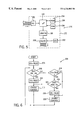
- FIG. 5 is a block diagram of an implement control system
- FIG. 6 is a schematic diagram of a portion of a program for the control system of FIG. 5 .
- FIG. 1 shows a work vehicle 102 including a tractor 104 and a soil excavating implement, or backhoe 106 .
- Tractor 104 includes a frame 108 supported by wheels 109 , crawler treads, or the like, as well as an operator's station 110 having a seat 112 and an operator input device console 114 .
- Backhoe 106 includes a material engaging member shown as a bucket 138 having an opening 140 and a plurality of members for positioning of bucket 138 , those members shown as a swing tower 120 affixed to frame 108 , a boom 124 movably secured to swing tower 120 , and a dipperstick 128 movably secured to boom 124 .
- Bucket 138 is movably secured to dipperstick 128 .
- Tractor-mounted backhoe 106 is shown as a L-Series Loader/Backhoe provided with an Extendahoe® dipperstick, both produced by Case Corporation, assignee of the present invention.
- Dipperstick 128 includes a first portion 130 and a second portion 132 which is telescoped with respect to first portion 130 , thereby providing bucket 138 with a greater reach from tractor 104 .
- a plurality of actuators is used to position the members described above with respect to each other and to thereby position bucket 138 with respect to frame 108 .
- the actuators are shown as hydraulic cylinders and include a left-side swing cylinder 122 and a right-side swing cylinder (not shown but configured as a mirror image of left-side swing cylinder 122 ); a boom cylinder 126 ; a dipperstick cylinder 134 ; and a bucket cylinder 142 .
- Dipperstick 128 includes a dipperstick extension cylinder 136 .
- Left-side swing cylinder 122 , right-side swing cylinder 122 b , boom cylinder 126 , dipperstick cylinder 134 , extension cylinder 136 , and bucket cylinder 142 are controlled by an operator disposed at operator's station 110 , generally in a first operator position upon seat 112 which is located and disposed for a good operator view of the work being performed by bucket 138 and for good access to manual operator input devices, or operator input devices (FIGS. 2 and 3 ), which are located at console 114 and are used to provide operator input or commands, to a bucket position control system 170 (FIG. 5 ).
- Work vehicle 102 may also include stabilizers 116 , which are positioned by the operator using operator input devices at console 114 . The operator input devices extend stabilizer cylinders 118 to position stabilizers 116 into contact with the soil.
- FIG. 2 shows a preferred embodiment of a portion of operator's station 110 including seat 112 and a console 114 a .
- Seat 112 is shown in a rearward facing position, oriented for operation of backhoe 106 , and may be reoriented to a forward facing position for driving of work vehicle 102 .
- Console 114 a includes a plurality of operator input devices, shown as levers and pedals, which are used by the operator to provide bucket position commands to control system 170 (FIG. 5 ).
- Bucket position commands may be provided by positioning of spools within hydraulic directional and flow control valves, with the spools mechanically connected to operator input devices; in the form of hydraulic pressure signals from pilot valves connected to operator input devices and routed to pilot-controlled directional and flow control valves; and/or in the form of electronic signals from transducers (e.g., potentiometers, variable differential transformers, encoders) coupled to operator input devices and controlling hydraulic valve drivers through control system 170 .
- Electronic signals may be analog (e.g., voltage or current level), pulse width modulated (PWM), or digitally encoded.
- Operator input devices located at or upon console 114 a include a dipperstick/swing joystick 148 , a boom/bucket joystick 146 , and stabilizer levers 152 a .
- pedals 154 and 156 may be included for auxiliary functions of generally unrelated accessories, or may be used to control swing and the dipperstick/swing joystick replaced by a dipperstick (only) lever.
- Dipperstick/swing joystick 148 is pushed away from the operator to command dipperstick 128 to move away from the operator, pulled toward the operator to command dipperstick 128 to move toward the operator, pushed to the operator's left to command boom 124 to swing to the operator's left, and pushed to the operator's right to command boom 124 to swing to the operator's right.
- Boom/Bucket joystick 146 is pushed away from the operator to command boom 124 to move away from the operator, pulled toward the operator to command boom 124 to move toward the operator, pushed to the operator's left to command bucket 138 to tilt opening 140 up, and pushed to the operator's right to command bucket 138 to tilt opening 140 down.
- Stabilizer levers 152 a are pushed away from the operator to command the corresponding stabilizers 116 to lower and pulled toward the operator to command the corresponding stabilizers 116 to raise.
- Pedals 154 , 156 may be used to control flow of hydraulic fluid to accessories, e.g., hydraulic torque wrenches, dewatering pumps, etc.
- a first operator presence sensor is shown, for example, as a seat switch 144 located within seat 112 , and is configured and disposed to change state (i.e., to open or close electrical contacts) when weight is placed upon seat 112 .
- Seat switch 144 is coupled to control circuit 172 (e.g., through a chassis wiring harness or through a vehicle CAN bus).
- Control system 170 shown in FIG.
- 5) is configured to enable operator input device of the position of bucket 138 (e.g., by coupling operator input devices to valve drivers) when a weight is sensed (i.e., when an operator is seated) and to disable operator input device of the position of bucket 138 (e.g., by uncoupling operator input devices from valve drivers) when a weight is not sensed (i.e., when seat 112 is vacant in a manner discussed more fully below).
- a seat switch may be located under seat 112 , i.e., within support structure for seat 112 or between the support structure and the floor of operator's station 110 .
- a load cell may be used instead of a switch to sense weight upon seat 112 , a signal corresponding to the weight sensed sent to control system 170 , and digital logic used within control system 170 to enable or disable operator input device of bucket position in correspondence with a predetermined threshold signal level corresponding to the amount of weight upon seat 112 .
- the amount of weight required for a change of state in bucket position control enablement is approximately 30 pounds to preclude inadvertent enablement (e.g., by debris in the seat) and inadvertent disablement (e.g., by transient unweighting due to the operator shifting his position in the seat).
- FIG. 3 shows an alternative embodiment of an operator input device console, in which a console 114 b is provided with a plurality of levers, which are grouped in an in-line relationship, and with two pedals.
- a boom lever 158 is pushed away from the operator to command boom 124 to move away from the operator and pulled toward the operator to command boom 124 to move toward the operator.
- a dipperstick lever 160 is pushed away from the operator to command dipperstick 128 to move away from the operator and pulled toward the operator to command dipperstick 128 to move toward the operator.
- a bucket lever 162 is pushed away from the operator to command bucket 138 to tilt opening 140 down and pulled toward the operator to command bucket 138 to tilt opening 140 up.
- Either or both stabilizer levers 152 b are pushed away from the operator to command the corresponding stabilizers 116 to lower and pulled toward the operator to command the corresponding stabilizers 116 to raise.
- a right-side swing pedal 166 is depressed to command boom 124 to swing to the operator's right, and a left-side swing pedal 164 is depressed to command boom 124 to swing to the operator's left.
- control console configurations including variations in combinations of levers, joysticks and pedals are generally available, and one of them is specified or selected by a purchaser of backhoe 106 at the time of purchase.
- Each configuration generally conforms to one of a variety of defacto industry standards in control element location and range of motion, each such defacto standard relating to a particular backhoe manufacturer's preferred or customary arrangement and implementation of such control elements.
- the two configurations discussed above and shown in FIGS. 2 and 3 shall be understood to be merely typical and representative, and not all-inclusive.
- FIG. 4 shows an operator input device lever or joystick provided with a second operator presence sensor, shown as an override switch 168 .
- Override switch 168 is a momentary contact switch; i.e., a switch which changes state only while engaged by the operator and which includes a spring for automatic return to a default, nonengaged position when released by the operator.
- Override switch 168 is coupled to a microprocessor 190 of control system 170 , and is used by the operator to override a disabling of bucket position control which would otherwise occur when he rises from the first operator position in seat 112 to stand in a second operator position near seat 112 (e.g., to temporarily position bucket 138 at the bottom of a deep trench not sufficiently visible from the seated position).
- override switch 168 is secured to boom/bucket joystick 148 of console 114 a (or to boom lever 158 of console 114 b ) and control system 170 is configured to allow override of disablement of bucket position control (i.e., to allow continued bucket position control) when the seated operator depresses override switch 168 and then rises from seat 112 while holding override switch 168 depressed.
- the operator is thereby able to control position of backhoe 106 while in a standing position at console 114 , provided he has depressed override switch 168 prior to rising from seat 112 , for as long as he continuously maintains engagement with override switch 168 , i.e., holds override switch 168 depressed.
- two operator input devices are provided with override switches 168 so that the operator may maintain bucket position control from a standing position by depressing and maintaining depressed either of override switches 168 before rising from seat 112 , and then depressing and maintaining depressed the other override switch 168 before releasing the initially depressed override switch 168 if he wishes to switch hands (e.g., to manipulate another lever located on the same side of console 114 as is the initially depressed override switch.
- One of the two override switches 168 is secured to boom lever 158 and the other of the override switches 168 is secured to bucket lever 162 .
- the operator does not have to sometimes cross hands (i.e., manipulate an operator input device on his left side with his right hand or conversely).
- presence of an operator disposed at control console 114 in seated and/or standing positions may be sensed by a sensor which generates a signal when impinged upon by a beam of energy transmitted from an aligned source of energy; e.g., a photodiode receiving a narrow beam of infrared light from an aligned, collimating infrared lamp or light-emitting diode.
- a photodiode changes state when light having flux above a threshold value is beamed upon it and the beam is not interrupted.
- an invisible spectrum e.g., infrared
- inadvertent photodiode change of state in conditions of high ambient brightness e.g., bright sunlight.
- the light source is disposed on one side of the operator and the sensor on the other. When the operator is present his body interrupts the light beam and the sensor does not sense the light, whereas when the operator is absent the light beam reaches the sensor and the sensor senses the light.
- light beams may be oriented transversely with respect to tractor 104 with a first light source and a first photodiode located in correspondence with the seated position of the operator, and a second light source and a second photodiode located in correspondence with the standing position of the operator.
- a single light source may be located behind the operator and aimed toward a single photodiode disposed in front of the operator, the operator thereby interrupting the light beam in both seated and standing positions.
- FIG. 5 shows a preferred embodiment of bucket position control system 170 including a control circuit 172 .
- Control system 170 includes a microprocessor 190 , a random-access memory (RAM) 194 , a nonvolatile read-only memory (ROM) 196 , a driver circuit 198 and an input conditioning circuit (ICC) 192 .
- RAM 194 , ROM 196 , ICC 192 and driver circuit 198 are in communication with microprocessor 190 , e.g., through a bus.
- Microprocessor 190 communicates and executes command instructions in accordance with a program 204 stored in ROM 196 , and stores data in specific addressed registers within RAM 194 . When instructed by a command from program 204 , microprocessor 190 retrieves data from a specific address within RAM 194 and utilizes it in executing program 204 .
- Bucket position control system 170 performs various activities related to the positioning of bucket 138 with respect to frame 108 , among those activities being the enabling and disabling of actuator response to operator input device (i.e., operator input) bucket position commands.
- the enabling and disabling activities are performed by microprocessor 190 within control system 170 in accordance with data retrieved by microprocessor 190 from RAM 194 as directed by program 204 instructions. These data include representations of operator presence or lack of presence in seat 112 or at console 114 .
- microprocessor 190 enables operator input control of bucket 138 position by accepting, processing and transmitting (when data in RAM indicates that an operator is present) to driver circuit 198 signals generated by operator input devices at console 114 , and disables such control (when data in RAM does not indicate that an operator is present) by not accepting, processing and/or transmitting the operator input signals.
- ICC 192 includes signal modulating and converting (e.g., analog-to-digital or A/D) apparatus typical of vehicular and equipment electronics. If control system 170 acquires data from other sources (e.g., cylinder position sensors), a multiplexer may be included to sample signals into a single A/D converter.
- A/D analog-to-digital
- Driver circuit 198 processes and converts control signals generated by microprocessor 190 in accordance with program 204 in order to make them compatible with bucket 138 positioning cylinders, e.g., digital-to-analog (A/D) conversion, pulse width modulation (PWM) and voltage or current modulation for use in, e.g., hydraulic directional and flow control valves located in the paths of flow from a hydraulic power unit (HPU) 202 to left- and right-side swing cylinders 122 and respectively, boom cylinder 126 , dipperstick cylinder 134 , extension cylinder 136 and bucket cylinder 142 .
- A/D digital-to-analog
- PWM pulse width modulation
- VPU hydraulic directional and flow control valves located in the paths of flow from a hydraulic power unit (HPU) 202 to left- and right-side swing cylinders 122 and respectively, boom cylinder 126 , dipperstick cylinder 134 , extension cylinder 136 and bucket cylinder 142 .
- HPU hydraulic
- FIG. 6 shows schematically a preferred embodiment of a portion of program 204 stored within ROM 196 , that portion dealing with enabling and disabling of bucket 138 position control by effectively connecting or disconnecting, respectively, the operator input devices on console 114 a or 114 b with respect to control circuit 172 , or effectively disabling control circuit 172 of control system 170 .
- ICC 192 may be connected or disconnected with respect to microprocessor 190 and/or microprocessor 190 with respect to driver circuit 198 .
- Program 204 first sets a flag “ON” to “false” in block 206 .
- Microprocessor 190 then checks seat switch 144 to determine if the operator is present on seat 112 in block 208 . If the operator is present on seat 112 , the “ON” flag is set to “true” in block 210 and control circuit 172 response to any bucket 138 position command generated by the operator is enabled in block 212 . When thus enabled, microprocessor 190 translates the operator's movement of the operator input devices into signals that are applied to valve drivers 198 to provide the commanded motions. Program 204 execution then returns to block 208 and seat switch 144 is tested again. The above seat-checking and enabling operation is repeated indefinitely as long as the operator is present on seat 112 . Thus, for as long as the operator is present on seat 112 , control circuit 172 will respond to the operator commands.
- program 204 flow changes. If the operator holds override switches 168 down, control circuit 172 is still enabled (not disabled) for as long as the operator is out of seat 112 .
- the “Seat Switch ‘On’?” test of block 208 fails, and program 204 flow branches to block 214 .
- microprocessor 190 checks to see if the “ON” flag is set to “true.” Assuming the operator has never left seat 112 since program 204 execution began, the “ON” flag will be “true,” and program 204 flow will branch to block 216 in which microprocessor 190 determines if override switches 168 are being actuated by the operator.
- microprocessor 190 will branch to the “yes” path out of block 216 and control will be enabled, as discussed above, in block 212 . Again, program 204 execution returns to block 208 and microprocessor 190 repeatedly checks the “ON” flags of blocks 208 , 214 and 216 and enables the operator input devices indefinitely. Thus, when the operator actuates override switches 168 before leaving seat 112 , the operator input devices are still enabled and are maintained enabled for so long as override switches 168 are actuated by the operator.
- program 204 executes block 208 , thereby determining that the operator is not present in seat 112 , then executes block 214 thereby determining that the “ON” flag is “true” just as in the previous paragraph.
- microprocessor 190 determines that override switches 168 have been released (i.e., the override is “off”) and branches to block 218 where the “ON” flag is set to “false,” and thence to block 220 where the operator input devices are disabled.
- program 204 again returns to block 208 to check seat switch 144 and branches to block 214 to check the “ON” flag, since the operator is still out of seat 112 . This time, however, since the “ON” flag is “false,” program 204 execution branches directly to block 220 where control circuit 172 is disabled. Program 204 execution cycles through blocks 208 , 214 and 220 , keeping control circuit 172 disabled indefinitely. Even if the operator again actuates override switches 168 while still not seated in seat 112 , control circuit 172 will still be disabled, since program 204 flow now bypasses block 216 (the override “on” block).
- control circuit 172 is enabled. If the operator rises from seat 112 with override buttons 168 depressed, control circuit 172 remains enabled. Once the operator releases override switches 168 while out of seat 112 , control circuit 172 is disabled, and remains disabled until the operator returns to seat 112 . If the operator ever rises from seat 112 without override switches 168 being actuated, control circuit 172 is disabled and remains disabled until the operator returns to seat 112 .
- control circuitry maybe embodied in discrete digital circuits, analog circuits, hydraulic circuits, pneumatic circuits or any combination thereof.
Abstract
Description
Claims (22)
Priority Applications (1)
| Application Number | Priority Date | Filing Date | Title |
|---|---|---|---|
| US09/354,480 US6226902B1 (en) | 1999-07-16 | 1999-07-16 | Operator presence system with bypass logic |
Applications Claiming Priority (1)
| Application Number | Priority Date | Filing Date | Title |
|---|---|---|---|
| US09/354,480 US6226902B1 (en) | 1999-07-16 | 1999-07-16 | Operator presence system with bypass logic |
Publications (1)
| Publication Number | Publication Date |
|---|---|
| US6226902B1 true US6226902B1 (en) | 2001-05-08 |
Family
ID=23393515
Family Applications (1)
| Application Number | Title | Priority Date | Filing Date |
|---|---|---|---|
| US09/354,480 Expired - Lifetime US6226902B1 (en) | 1999-07-16 | 1999-07-16 | Operator presence system with bypass logic |
Country Status (1)
| Country | Link |
|---|---|
| US (1) | US6226902B1 (en) |
Cited By (40)
| Publication number | Priority date | Publication date | Assignee | Title |
|---|---|---|---|---|
| US6377192B1 (en) * | 1998-04-23 | 2002-04-23 | Agco S.A. | Electronic control system |
| US6430850B1 (en) * | 2000-07-25 | 2002-08-13 | Deere & Company | Seat switch activated pump |
| US6643577B1 (en) | 2002-08-22 | 2003-11-04 | Caterpillar Inc | Operator control station and method for a work machine having more than one function |
| US20040026150A1 (en) * | 2002-08-06 | 2004-02-12 | Kubota Corporation | Work vehicle having overridable automatic engine stop circuit |
| US6694240B1 (en) | 2002-08-29 | 2004-02-17 | Caterpillar Inc | Control system for and method of operating a work machine |
| US20040194981A1 (en) * | 2002-12-20 | 2004-10-07 | Luca Destefanis | Earth-moving vehicle with device for configuration of profile for circulation on road |
| US20050093280A1 (en) * | 2003-10-31 | 2005-05-05 | Adam Jacob | Backhoe |
| US20050211449A1 (en) * | 2004-03-12 | 2005-09-29 | Clark Equipment Company | Automated attachment vibration system |
| US20050222733A1 (en) * | 2004-04-01 | 2005-10-06 | Deere & Company, A Delaware Corporation | Enabling system for an implement controller |
| US20060037805A1 (en) * | 2004-08-19 | 2006-02-23 | Komatsu Utility Europe S.P.A. | Earth moving machine |
| US20070074923A1 (en) * | 2004-09-23 | 2007-04-05 | Crown Equipment Corporation | Rotating and/or swiveling seat |
| US20070203630A1 (en) * | 2006-02-24 | 2007-08-30 | Vitale Andrew J | Work machine with operator presence detection strategy |
| WO2008066649A1 (en) * | 2006-11-30 | 2008-06-05 | Caterpillar Inc. | Preparation for machine repositioning in an excavating operation |
| US20090012679A1 (en) * | 2006-12-31 | 2009-01-08 | Caterpillar Inc | System and method for operating a machine |
| US20090313862A1 (en) * | 2008-06-24 | 2009-12-24 | Kensaku Wakuta | Working vehicle |
| US20100237692A1 (en) * | 2009-03-17 | 2010-09-23 | John Mlaker | Apparatus for Enabling an Aerial Lift Including a Self-Disabling Interlock |
| US20100320022A1 (en) * | 2006-09-14 | 2010-12-23 | David Joseph Klas | Machine control interlocks for an electrohydraulically controlled vehicle |
| US20120173092A1 (en) * | 2011-01-05 | 2012-07-05 | Sorby Mitchell L | Safety system for work vehicle |
| US20120298081A1 (en) * | 2010-02-07 | 2012-11-29 | Seran Alonzo B | Interlock safety switch |
| US20130197760A1 (en) * | 2008-12-04 | 2013-08-01 | Anthony T. Castaneda | Sensor configuration for a materials handling vehicle |
| US20140060954A1 (en) * | 2012-09-04 | 2014-03-06 | Polaris Industries Inc. | Side-by-side diesel utility vehicle |
| ITPD20130305A1 (en) * | 2013-11-12 | 2015-05-13 | Maschio Gaspardo Spa | AGRICULTURAL EQUIPMENT FOR REMOVABLE ATTACHMENT TO A TRACTOR, AS A BRUSH CUTTER, WITH PERFECT SECURITY. |
| US9493184B2 (en) | 2009-08-18 | 2016-11-15 | Crown Equipment Corporation | Steer maneuvers for materials handling vehicles |
| WO2017035620A1 (en) * | 2015-09-01 | 2017-03-09 | Flores Matheus Falleiros De Almeida Valladão | Safety system for electronic systems in vehicles with passengers |
| US20180079633A1 (en) * | 2006-09-14 | 2018-03-22 | Crown Equipment Corporation | Systems and methods of remotely controlling a materials handling vehicle |
| US20180187394A1 (en) * | 2012-06-08 | 2018-07-05 | Sumitomo Heavy Industries, Ltd. | Shovel control method and shovel control device |
| EP3382668A1 (en) * | 2006-09-14 | 2018-10-03 | Crown Equipment Corporation | Systems and methods of remotely controlling a materials handling vehicle |
| US20200190774A1 (en) * | 2017-12-27 | 2020-06-18 | Kubota Corporation | Working machine and manufacturing method of the same |
| WO2021067517A1 (en) * | 2019-09-30 | 2021-04-08 | Husco International, Inc. | Systems and methods for determining control capabilities on an off-highway vehicle |
| US11155166B2 (en) * | 2019-10-01 | 2021-10-26 | Caterpillar Inc. | Operator detection system |
| CN113614318A (en) * | 2019-03-25 | 2021-11-05 | 克拉克设备公司 | Mounting of an electrohydraulic power machine |
| US20220010531A1 (en) * | 2018-11-19 | 2022-01-13 | Caterpillar Inc. | Work machine with sensor enabled user control |
| US20220042281A1 (en) * | 2020-08-04 | 2022-02-10 | Caterpillar Inc. | Operator presence system |
| US20220194278A1 (en) * | 2020-12-21 | 2022-06-23 | Gugsoo An | Multi-joint driven console box for construction equipment |
| US11414832B2 (en) * | 2018-03-14 | 2022-08-16 | Komatsu Ltd. | Work vehicle |
| US11429095B2 (en) | 2019-02-01 | 2022-08-30 | Crown Equipment Corporation | Pairing a remote control device to a vehicle |
| US11591771B2 (en) * | 2018-10-26 | 2023-02-28 | Komatsu Ltd. | Work vehicle |
| US11626011B2 (en) | 2020-08-11 | 2023-04-11 | Crown Equipment Corporation | Remote control device |
| US11641121B2 (en) | 2019-02-01 | 2023-05-02 | Crown Equipment Corporation | On-board charging station for a remote control device |
| EP4296434A1 (en) * | 2022-06-22 | 2023-12-27 | Leica Geosystems Technology A/S | Improved determination of an excavator swing boom angle based on intermittent first interim swing boom angles |
Citations (15)
| Publication number | Priority date | Publication date | Assignee | Title |
|---|---|---|---|---|
| US3511328A (en) | 1969-08-18 | 1970-05-12 | Eldon L Webb | Power vehicle safety device |
| US3569726A (en) | 1969-06-26 | 1971-03-09 | Case Co J I | Ignition safety system for garden tractors |
| US3838748A (en) | 1973-01-30 | 1974-10-01 | Ridersafe Syst Inc | Safety system for vehicles |
| US4294327A (en) | 1978-12-15 | 1981-10-13 | Delta Systems, Inc. | Safety interlock for machine and engine with magneto ignition |
| US4385863A (en) | 1981-05-13 | 1983-05-31 | Sperry Corporation | Seat interlock for skid-steer loader |
| US4389154A (en) | 1981-05-13 | 1983-06-21 | Sperry Corporation | Time delay for a seat switch activated loader boom lock |
| US4476964A (en) | 1982-03-11 | 1984-10-16 | Outboard Marine Corporation | Seat-brake including lockout |
| US4607199A (en) | 1984-09-07 | 1986-08-19 | Outboard Marine Corporation | Computer controlled safety seat switch |
| US4664218A (en) | 1984-10-05 | 1987-05-12 | National Emstop, Inc. | Safety back-up system for vehicles |
| US4699561A (en) | 1986-05-08 | 1987-10-13 | J. I. Case Company | Engine interlock control system for a material handling implement |
| US5203440A (en) | 1992-06-24 | 1993-04-20 | Deere & Company | Interlock circuit for a vehicle with an optical second drive |
| US5425431A (en) | 1994-02-18 | 1995-06-20 | Clark Equipment Company | Interlock control system for power machine |
| US5481078A (en) | 1994-02-18 | 1996-01-02 | Clark Equipment Company | Operator presence sensor for operator's seat |
| US5551523A (en) | 1994-02-18 | 1996-09-03 | Clark Equipment Company | Traction lock |
| US5577876A (en) | 1994-02-22 | 1996-11-26 | Clark Equipment Company | Hydraulic interblock system |
-
1999
- 1999-07-16 US US09/354,480 patent/US6226902B1/en not_active Expired - Lifetime
Patent Citations (15)
| Publication number | Priority date | Publication date | Assignee | Title |
|---|---|---|---|---|
| US3569726A (en) | 1969-06-26 | 1971-03-09 | Case Co J I | Ignition safety system for garden tractors |
| US3511328A (en) | 1969-08-18 | 1970-05-12 | Eldon L Webb | Power vehicle safety device |
| US3838748A (en) | 1973-01-30 | 1974-10-01 | Ridersafe Syst Inc | Safety system for vehicles |
| US4294327A (en) | 1978-12-15 | 1981-10-13 | Delta Systems, Inc. | Safety interlock for machine and engine with magneto ignition |
| US4385863A (en) | 1981-05-13 | 1983-05-31 | Sperry Corporation | Seat interlock for skid-steer loader |
| US4389154A (en) | 1981-05-13 | 1983-06-21 | Sperry Corporation | Time delay for a seat switch activated loader boom lock |
| US4476964A (en) | 1982-03-11 | 1984-10-16 | Outboard Marine Corporation | Seat-brake including lockout |
| US4607199A (en) | 1984-09-07 | 1986-08-19 | Outboard Marine Corporation | Computer controlled safety seat switch |
| US4664218A (en) | 1984-10-05 | 1987-05-12 | National Emstop, Inc. | Safety back-up system for vehicles |
| US4699561A (en) | 1986-05-08 | 1987-10-13 | J. I. Case Company | Engine interlock control system for a material handling implement |
| US5203440A (en) | 1992-06-24 | 1993-04-20 | Deere & Company | Interlock circuit for a vehicle with an optical second drive |
| US5425431A (en) | 1994-02-18 | 1995-06-20 | Clark Equipment Company | Interlock control system for power machine |
| US5481078A (en) | 1994-02-18 | 1996-01-02 | Clark Equipment Company | Operator presence sensor for operator's seat |
| US5551523A (en) | 1994-02-18 | 1996-09-03 | Clark Equipment Company | Traction lock |
| US5577876A (en) | 1994-02-22 | 1996-11-26 | Clark Equipment Company | Hydraulic interblock system |
Non-Patent Citations (1)
| Title |
|---|
| Case Loader/Backhoe Brochure, 580L, Case Corporation, Racine, WI, 1996. |
Cited By (74)
| Publication number | Priority date | Publication date | Assignee | Title |
|---|---|---|---|---|
| US6377192B1 (en) * | 1998-04-23 | 2002-04-23 | Agco S.A. | Electronic control system |
| US6430850B1 (en) * | 2000-07-25 | 2002-08-13 | Deere & Company | Seat switch activated pump |
| US20040026150A1 (en) * | 2002-08-06 | 2004-02-12 | Kubota Corporation | Work vehicle having overridable automatic engine stop circuit |
| US20060113139A1 (en) * | 2002-08-06 | 2006-06-01 | Keishiro Nishi | Work vehicle having overridable automatic engine stop circuit |
| US7337866B2 (en) * | 2002-08-06 | 2008-03-04 | Kubota Corporation | Work vehicle having overridable automatic engine stop circuit |
| US7007768B2 (en) * | 2002-08-06 | 2006-03-07 | Kubota Corporation | Work vehicle having overridable automatic engine stop circuit |
| US6643577B1 (en) | 2002-08-22 | 2003-11-04 | Caterpillar Inc | Operator control station and method for a work machine having more than one function |
| US6694240B1 (en) | 2002-08-29 | 2004-02-17 | Caterpillar Inc | Control system for and method of operating a work machine |
| US20040194981A1 (en) * | 2002-12-20 | 2004-10-07 | Luca Destefanis | Earth-moving vehicle with device for configuration of profile for circulation on road |
| US7017289B2 (en) * | 2002-12-20 | 2006-03-28 | Cnh America Llc | Earth-moving vehicle with device for configuration of profile for circulation on road |
| US20050093280A1 (en) * | 2003-10-31 | 2005-05-05 | Adam Jacob | Backhoe |
| US20050211449A1 (en) * | 2004-03-12 | 2005-09-29 | Clark Equipment Company | Automated attachment vibration system |
| US7117952B2 (en) * | 2004-03-12 | 2006-10-10 | Clark Equipment Company | Automated attachment vibration system |
| US20050222733A1 (en) * | 2004-04-01 | 2005-10-06 | Deere & Company, A Delaware Corporation | Enabling system for an implement controller |
| EP1584756A3 (en) * | 2004-04-01 | 2006-04-05 | Deere & Company | Activation system for a device control arrangement |
| US7283903B2 (en) | 2004-04-01 | 2007-10-16 | Deere & Company | Enabling system for an implement controller |
| US20060037805A1 (en) * | 2004-08-19 | 2006-02-23 | Komatsu Utility Europe S.P.A. | Earth moving machine |
| US7243756B2 (en) * | 2004-08-19 | 2007-07-17 | Komatsu Utility Europe S.P.A. | Earth moving machine |
| US7347299B2 (en) * | 2004-09-23 | 2008-03-25 | Crown Equipment Corporation | Rotating and/or swiveling seat |
| US20070074923A1 (en) * | 2004-09-23 | 2007-04-05 | Crown Equipment Corporation | Rotating and/or swiveling seat |
| US20070203630A1 (en) * | 2006-02-24 | 2007-08-30 | Vitale Andrew J | Work machine with operator presence detection strategy |
| US7899597B2 (en) | 2006-02-24 | 2011-03-01 | Caterpillar Inc. | Work machine with operator presence detection strategy |
| US20100320022A1 (en) * | 2006-09-14 | 2010-12-23 | David Joseph Klas | Machine control interlocks for an electrohydraulically controlled vehicle |
| EP3382668A1 (en) * | 2006-09-14 | 2018-10-03 | Crown Equipment Corporation | Systems and methods of remotely controlling a materials handling vehicle |
| US10179723B2 (en) * | 2006-09-14 | 2019-01-15 | Crown Equipment Corporation | Systems and methods of remotely controlling a materials handling vehicle |
| US20180079633A1 (en) * | 2006-09-14 | 2018-03-22 | Crown Equipment Corporation | Systems and methods of remotely controlling a materials handling vehicle |
| US7918303B2 (en) * | 2006-09-14 | 2011-04-05 | Deere & Company | Machine control interlocks for an electrohydraulically controlled vehicle |
| US7753132B2 (en) | 2006-11-30 | 2010-07-13 | Caterpillar Inc | Preparation for machine repositioning in an excavating operation |
| US20080133093A1 (en) * | 2006-11-30 | 2008-06-05 | Daniel Stanek | Preparation for machine repositioning in an excavating operation |
| WO2008066649A1 (en) * | 2006-11-30 | 2008-06-05 | Caterpillar Inc. | Preparation for machine repositioning in an excavating operation |
| US20090012679A1 (en) * | 2006-12-31 | 2009-01-08 | Caterpillar Inc | System and method for operating a machine |
| US20090018745A1 (en) * | 2006-12-31 | 2009-01-15 | Caterpillar Inc | System and method for operating a machine |
| US8041485B2 (en) | 2006-12-31 | 2011-10-18 | Caterpillar Inc. | System and method for operating a machine |
| US7857086B2 (en) * | 2008-06-24 | 2010-12-28 | Yanmar Co., Ltd. | Working vehicle |
| US20090313862A1 (en) * | 2008-06-24 | 2009-12-24 | Kensaku Wakuta | Working vehicle |
| US10301155B2 (en) | 2008-12-04 | 2019-05-28 | Crown Equipment Corporation | Sensor configuration for a materials handling vehicle |
| US20130197760A1 (en) * | 2008-12-04 | 2013-08-01 | Anthony T. Castaneda | Sensor configuration for a materials handling vehicle |
| US9522817B2 (en) * | 2008-12-04 | 2016-12-20 | Crown Equipment Corporation | Sensor configuration for a materials handling vehicle |
| US7915752B2 (en) * | 2009-03-17 | 2011-03-29 | Utility Truck Equipment & Parts, LLC | Apparatus for enabling an aerial lift including a self-disabling interlock |
| US20100237692A1 (en) * | 2009-03-17 | 2010-09-23 | John Mlaker | Apparatus for Enabling an Aerial Lift Including a Self-Disabling Interlock |
| US9493184B2 (en) | 2009-08-18 | 2016-11-15 | Crown Equipment Corporation | Steer maneuvers for materials handling vehicles |
| US20120298081A1 (en) * | 2010-02-07 | 2012-11-29 | Seran Alonzo B | Interlock safety switch |
| US20120173092A1 (en) * | 2011-01-05 | 2012-07-05 | Sorby Mitchell L | Safety system for work vehicle |
| US20180187394A1 (en) * | 2012-06-08 | 2018-07-05 | Sumitomo Heavy Industries, Ltd. | Shovel control method and shovel control device |
| US11248361B2 (en) * | 2012-06-08 | 2022-02-15 | Sumitomo Heavy Industries, Ltd. | Shovel control method and shovel control device |
| US10915600B2 (en) | 2012-09-04 | 2021-02-09 | Polaris Industries Inc. | Side-by-side diesel utility vehicle |
| US10037304B2 (en) | 2012-09-04 | 2018-07-31 | Polaris Industries Inc. | Side-by-side diesel utility vehicle |
| US9022160B2 (en) * | 2012-09-04 | 2015-05-05 | Polaris Industries Inc. | Side-by-side diesel utility vehicle |
| US20140060954A1 (en) * | 2012-09-04 | 2014-03-06 | Polaris Industries Inc. | Side-by-side diesel utility vehicle |
| US9063832B2 (en) | 2012-09-04 | 2015-06-23 | Polaris Industries Inc. | Side-by-side diesel utility vehicle |
| US9152607B2 (en) | 2012-09-04 | 2015-10-06 | Polaris Industries Inc. | Side-by-side diesel utility vehicle |
| US9075699B2 (en) | 2012-09-04 | 2015-07-07 | Polaris Industries Inc. | Side-by-side diesel utility vehicle |
| ITPD20130305A1 (en) * | 2013-11-12 | 2015-05-13 | Maschio Gaspardo Spa | AGRICULTURAL EQUIPMENT FOR REMOVABLE ATTACHMENT TO A TRACTOR, AS A BRUSH CUTTER, WITH PERFECT SECURITY. |
| EP2878186A1 (en) * | 2013-11-12 | 2015-06-03 | Maschio Gaspardo S.p.A. | Agricultural implement, such as an extendable brush cutter, with improved safety for removable attachment to a tractor |
| WO2017035620A1 (en) * | 2015-09-01 | 2017-03-09 | Flores Matheus Falleiros De Almeida Valladão | Safety system for electronic systems in vehicles with passengers |
| US20200190774A1 (en) * | 2017-12-27 | 2020-06-18 | Kubota Corporation | Working machine and manufacturing method of the same |
| US11781291B2 (en) * | 2017-12-27 | 2023-10-10 | Kubota Corporation | Working machine and manufacturing method of the same |
| US11414832B2 (en) * | 2018-03-14 | 2022-08-16 | Komatsu Ltd. | Work vehicle |
| US11591771B2 (en) * | 2018-10-26 | 2023-02-28 | Komatsu Ltd. | Work vehicle |
| US11946229B2 (en) * | 2018-11-19 | 2024-04-02 | Caterpillar Inc. | Work machine with sensor enabled user control |
| US20220010531A1 (en) * | 2018-11-19 | 2022-01-13 | Caterpillar Inc. | Work machine with sensor enabled user control |
| US11641121B2 (en) | 2019-02-01 | 2023-05-02 | Crown Equipment Corporation | On-board charging station for a remote control device |
| US11429095B2 (en) | 2019-02-01 | 2022-08-30 | Crown Equipment Corporation | Pairing a remote control device to a vehicle |
| US11500373B2 (en) | 2019-02-01 | 2022-11-15 | Crown Equipment Corporation | On-board charging station for a remote control device |
| CN113614318A (en) * | 2019-03-25 | 2021-11-05 | 克拉克设备公司 | Mounting of an electrohydraulic power machine |
| GB2602432A (en) * | 2019-09-30 | 2022-06-29 | Husco Int Inc | Systems and methods for determining control capabilities on an off-highway vehicle |
| GB2602432B (en) * | 2019-09-30 | 2023-10-04 | Husco Int Inc | Systems and methods for determining control capabilities on an off-highway vehicle |
| WO2021067517A1 (en) * | 2019-09-30 | 2021-04-08 | Husco International, Inc. | Systems and methods for determining control capabilities on an off-highway vehicle |
| US11920326B2 (en) | 2019-09-30 | 2024-03-05 | Husco International, Inc. | Systems and methods for determining control capabilities on an off-highway vehicle |
| US11155166B2 (en) * | 2019-10-01 | 2021-10-26 | Caterpillar Inc. | Operator detection system |
| US20220042281A1 (en) * | 2020-08-04 | 2022-02-10 | Caterpillar Inc. | Operator presence system |
| US11626011B2 (en) | 2020-08-11 | 2023-04-11 | Crown Equipment Corporation | Remote control device |
| US20220194278A1 (en) * | 2020-12-21 | 2022-06-23 | Gugsoo An | Multi-joint driven console box for construction equipment |
| EP4296434A1 (en) * | 2022-06-22 | 2023-12-27 | Leica Geosystems Technology A/S | Improved determination of an excavator swing boom angle based on intermittent first interim swing boom angles |
Similar Documents
| Publication | Publication Date | Title |
|---|---|---|
| US6226902B1 (en) | Operator presence system with bypass logic | |
| JP5161115B2 (en) | Work machine performing operator presence detection method | |
| CA2716175C (en) | Carrier and backhoe control system and method | |
| EP1346268B1 (en) | Hand grip with microprocessor for controlling a power machine | |
| US7036248B2 (en) | Pattern select valve for control levers of a title work vehicle | |
| CA2839316C (en) | Electronic tag along | |
| US10061343B2 (en) | Motion coupling of multiple electronic control inputs | |
| US20160032564A1 (en) | Multiple Control Patterns for Machines with Hand and Foot Controls | |
| US7017674B2 (en) | Method of changing operating characteristics of an implement | |
| US9643648B2 (en) | Single pedal propulsion system for straight travel of work vehicle | |
| US20130204499A1 (en) | Machine With Four Degrees Of Freedom Implement Control Joystick And Track Type Tractor Using Same | |
| US6260357B1 (en) | Quick coupler control system | |
| WO1999058771A1 (en) | Construction machinery | |
| KR100806269B1 (en) | Hydraulic exacavator | |
| US8820463B2 (en) | Safety control systems and methods for heavy equipment | |
| JPH0685449U (en) | Exhaust plate control device | |
| US20070253840A1 (en) | Control system using a single proportional valve | |
| US20020073833A1 (en) | Return to dig system | |
| KR100991310B1 (en) | apparatus for controlling oil pressure of excavator breaker | |
| JPH073836A (en) | Working device controller of bulldozer | |
| US7210395B2 (en) | System for handling a tool at a vehicle | |
| KR200155594Y1 (en) | Two level position control device of boom for construction heavy equipment | |
| GB2574213A (en) | Work machine with travel mode and secondary steering controls | |
| KR102008021B1 (en) | Monitor control method using joystick | |
| JP2004340187A (en) | Hydraulic circuit of hydraulic attachment |
Legal Events
| Date | Code | Title | Description |
|---|---|---|---|
| AS | Assignment |
Owner name: CASE CORPORATION, WISCONSIN Free format text: ASSIGNMENT OF ASSIGNORS INTEREST;ASSIGNOR:HEYNE, DENNIS J.;REEL/FRAME:010119/0749 Effective date: 19990714 |
|
| STCF | Information on status: patent grant |
Free format text: PATENTED CASE |
|
| FPAY | Fee payment |
Year of fee payment: 4 |
|
| AS | Assignment |
Owner name: CNH AMERICA LLC, PENNSYLVANIA Free format text: ASSIGNMENT OF ASSIGNORS INTEREST;ASSIGNOR:CASE CORPORATION;REEL/FRAME:014981/0944 Effective date: 20040805 |
|
| AS | Assignment |
Owner name: CNH AMERICA LLC, PENNSYLVANIA Free format text: ASSIGNMENT OF ASSIGNORS INTEREST;ASSIGNOR:CNH AMERICA LLC;REEL/FRAME:017766/0484 Effective date: 20060606 Owner name: BLUE LEAF I.P., INC., DELAWARE Free format text: ASSIGNMENT OF ASSIGNORS INTEREST;ASSIGNOR:CNH AMERICA LLC;REEL/FRAME:017766/0484 Effective date: 20060606 |
|
| FPAY | Fee payment |
Year of fee payment: 8 |
|
| FPAY | Fee payment |
Year of fee payment: 12 |