US6206453B1 - Window protector assembly - Google Patents
Window protector assembly Download PDFInfo
- Publication number
- US6206453B1 US6206453B1 US09/397,748 US39774899A US6206453B1 US 6206453 B1 US6206453 B1 US 6206453B1 US 39774899 A US39774899 A US 39774899A US 6206453 B1 US6206453 B1 US 6206453B1
- Authority
- US
- United States
- Prior art keywords
- frame
- glazing
- window
- opening
- assembly
- Prior art date
- Legal status (The legal status is an assumption and is not a legal conclusion. Google has not performed a legal analysis and makes no representation as to the accuracy of the status listed.)
- Expired - Lifetime
Links
Images


Classifications
-
- B—PERFORMING OPERATIONS; TRANSPORTING
- B60—VEHICLES IN GENERAL
- B60J—WINDOWS, WINDSCREENS, NON-FIXED ROOFS, DOORS, OR SIMILAR DEVICES FOR VEHICLES; REMOVABLE EXTERNAL PROTECTIVE COVERINGS SPECIALLY ADAPTED FOR VEHICLES
- B60J1/00—Windows; Windscreens; Accessories therefor
- B60J1/20—Accessories, e.g. wind deflectors, blinds
- B60J1/2094—Protective means for window, e.g. additional panel or foil, against vandalism, dirt, wear, shattered glass, etc.
Definitions
- the present invention relates to protective devices for protecting windows from damage and, more specifically, concerns a replaceable window protector assembly adapted to protect and allow replacement of the glazing used in windows in public transportation vehicles, such as buses and trains.
- the interior surface of the glazing is damaged as a result of the actions of individuals sitting inside of the vehicle while the vehicle is moving.
- public transportation vehicles are increasingly being defaced or vandalized while the vehicles are sitting at rest. This can result in additional damage or defacement of the outside of the windows.
- the vandalism takes the form of crude or otherwise disagreeable expressions being permanently marked onto the windows.
- U.S. Pat. No. 5,242,207 which is owned by the assignee of this application, discloses one type of window protector which protects the interior surface of the glazing of the window from damage as a result of vandalism or defacement.
- U.S. Pat. No. 5,242,207 discloses a window protector which includes a protective sheet that is positioned against the interior surface of the glazing of the window and is held in place by a plurality of brackets which is attached to the frame of the window.
- These protective sheets act as a sacrificial surface that protects the glazing of the window from damage as a result of vandalism or defacement. From time to time, the protective sheet can be replaced with a new protective sheet by removing the brackets and positioning the new protective sheet adjacent the inner surface of the glazing of the window.
- window protector disclosed in U.S. Pat. No. 5,242,207 has been particularly effective in maintaining the integrity of the interior surface of the glazing of the window, this window protector does not provide any protection against damage to the outer surface of the glazing of the window. Moreover, if the protective layer on the interior surface of the window is not periodically replaced, it is possible that the glazing may be permanently damaged despite the best efforts of the window protector to protect the glazing.
- the window protector disclosed in U.S. Pat. No. 5,242,207 is designed to be used in conjunction with existing window frames such that replacement of the underlying glazing requires removal of the glazing from the existing transportation vehicle window frame. This can be a rather tedious process which increases the cost of maintaining and repairing the public transportation vehicle windows.
- the window protector assembly of the present invention which is comprised of a frame that defines a window opening, a piece of glazing adapted to be positioned within the window opening, a protective layer adapted to be positioned within the window opening so as to be adjacent one side of the glazing, and one or more retainers that are pivotally attached to the frame so as to be moveable between an opened position, which allows the glazing and protective layer to be positioned within the window opening or removed therefrom, and a closed position, wherein the retainer retains the protective layer and the glazing within the window opening.
- the one or more retainers are secured to the frame in the closed position by manipulation of a tool activated securing mechanism which is configured to inhibit unauthorized manipulation of the one or more retainers.
- the assembly includes a frame that defines a recess that has a first perimeter shape and is adapted to receive an outer protective layer having a perimeter shape substantially equivalent to the first perimeter shape, a piece of glazing having an outer perimeter shape substantially equivalent to the first perimeter shape, and an inner protective layer having an outer perimeter substantially equal to the first perimeter shape.
- the pivoting retaining members are preferably attached to the frame such that the pivoting retaining members also define an outer perimeter shape which is substantially equal to the first perimeter shape such that, when the retaining members are in the closed position, the retaining members exert force against substantially the entire outer perimeter of the outer protective layer, the glazing, and the inner protective layer to thereby retain the protective layers and the glazing within the opening of the frame.
- the retaining members cover substantially the entire outer perimeter of the protective layers and the glazing in the closed position, the edges of the protective layers and the glazing are not readily accessible to an unauthorized individual with the retaining members in the closed position.
- the frame has an interior surface that is positioned within the opening that is to receive the protective layers and the glazing.
- One or more pivot points are mounted on the interior surface such that the pivoting retaining members can be pivotally attached to the one or more pivot points.
- the one or more pivot points are preferably located on the interior surface in a location such that, when the pivoting retaining members are positioned in the closed position, the pivot points are enclosed by the frame and the pivoting retaining members such that access to the pivot points, when the pivoting retaining members are in the closed position, is inhibited. In this way, the likelihood of an unauthorized person removing the retaining members by damaging the pivot points is reduced.
- the retaining members retain the protective layers and the glazing within the recess defined by the frame
- removal and replacement of the protective layers and the glazing is simplified as compared to similar replacements using window protectors of the prior art.
- the user simply has to pivot the retaining members from the closed position to the opened position such that the protective layers and the glazing are exposed and then remove these layers from the recess defined by the frame.
- the simplified removal of the glazing and the protective layers permits replacement of the glazing and also allows for easy installation of an exterior protective sheet which has not been readily accomplished in designs of the prior art.
- FIG. 1 is an elevational view illustrating a public transportation vehicle incorporating windows having an embodiment of a window protector assembly of the present invention
- FIG. 2 is an inside elevational view illustrating the window protector assembly of FIG. 1;
- FIGS. 3A and 3B are cross-sectional views of the window protector assembly of FIG. 2 taken along the lines of 3 — 3 ;
- FIG. 4 is a cross-sectional view of the window protector assembly of FIG. 2 taken along the lines 4 — 4 ;
- FIGS. 5A and 5B are perspective views of the window protector assembly of FIG. 2, illustrating the assembly in both a closed and an opened configuration;
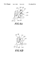
- FIGS. 6A and 6B are cross-sectional views of another embodiment of the window protector assembly of FIG. 2 illustrating another interconnection between retaining members of the window protector assembly and the frame of the window protector assembly;
- FIG. 7 is a side cross-sectional view of a securing mechanism of the assembly of FIG. 2;
- FIG. 8 is a top view of the securing mechanism of FIG. 1 .
- FIG. 1 illustrates an exemplary public transportation vehicle 100 that incorporates windows 102 having window frames 114 mounted within openings 106 in the side wall 110 of the vehicle 100 .
- the window protector assembly 112 can be used in a number of different applications including other types of public transportation vehicles and also in windows that are positioned in fixed environments, such as buildings, where the window is likely to be damaged or defaced through vandalism.
- the window protector assembly of the preferred embodiment is designed to both protect the glazing of the window and also to facilitate rapid change and replacement of protective sheets and the glazing of the window protector assembly.
- the window protector assembly 112 incorporates a frame 114 that is adapted to mount within the opening 106 in the side wall 110 of the vehicle 100 in a well-known manner.
- the frame 114 defines an opening 116 into which one or more pieces of glazing 120 are to be positioned.
- glazing refers to either glass windows or windows formed of any other generally transparent or translucent material.
- a first retaining member 122 and a second retaining member 124 are pivotally mounted to the frame 114 so as to be positioned about the outer perimeter of the opening 116 in the frame 114 .
- the first retaining member 122 is generally U-shaped having two arms 123 a , 123 b that extend along the side walls of the frame 114 and pivoting section 127 .
- the second retaining member 124 is also generally U-shaped having a pivoting section 128 and two arms 125 a , 125 b that also extend along the side walls of the frame 114 so as to engage with the two arms 123 a , 123 b of the first retaining member 122 .
- the pivoting section 127 of the first retaining member 122 and the pivoting section 128 of the second retaining member 124 are pivotally attached to the frame 114 so as to be pivotable between a closed position, as shown in FIG. 2, and an opened position whereby the outer perimeter of the glazing 120 and any protective layer is exposed.
- the arms and pivoting sections of the first retaining member 122 and the second retaining member 124 are selected to have a width sufficient so as to fully cover the outer edge of the glazing 120 and any protective layers positioned within the opening 116 of the frame 114 .
- FIGS. 3A and 3B illustrate the interconnection between the first retaining member 122 and the second retaining member 124 and corresponding sections of the frame 114 .
- the frame 114 includes an upper frame section 130 a and a lower frame section 130 b .
- the upper and lower frame sections 130 a , 130 b have an L-shaped section 132 that is suitable for mounting in the opening 106 of the side wall 110 of the vehicle 100 .
- the L-shaped section 132 has an exterior lip 134 that is adapted to mount flush against the outer surface of the side wall 110 of the vehicle adjacent the window openings 106 .
- the L-shaped section 132 further includes a laterally extending member 136 that is adapted to be positioned adjacent the inner walls of the openings 106 in the side walls 110 of the vehicle so as to extend substantially through the opening 106 .
- a pivoting member 140 is formed on an inner wall 142 of the laterally extending member 136 so as to extend perpendicularly outward therefrom into the opening 116 defined by the frame 114 .
- the pivoting member 140 extends the full length of the upper frame section 130 a and the lower frame section 130 b , and provides a surface to which the pivoting section 127 of the first retaining member 122 and the pivoting section 128 of the second retaining member 124 can be respectively attached to the frame 114 of the window protector assembly 112 .
- the L-shaped section 132 also defines a seating member 144 that extends inward into the opening 116 defined by the window frame 114 .
- the seating member 144 is adapted to receive a seal 146 that is retained in the seating member 144 as a result of a deformable section 150 of the seal 146 being positioned within an opening 152 formed in the seating member 144 of the upper and lower frame members 130 a , 130 b .
- the seal 146 is press-fit within the seating member 144 of the upper frame section 130 a and lower frame section 130 b .
- the upper and lower frame sections 130 a , 130 b have been described as being comprised of a plurality of discrete components, in the illustrated embodiment, the upper frame section 130 a and the lower frame section 130 b are comprised of a single uniform component preferably formed of extruded or molded aluminum.
- the pivoting members 140 are positioned on the inner surface 142 of the L-shaped section 132 so that the pivoting member 140 is positioned within the opening 116 of the window frame 114 .
- the pivoting sections 127 and 128 of the retaining members 122 and 124 define an opening 141 that receives the pivoting member 140 to permit the pivoting movement of the retaining members 122 and 124 .
- the pivoting member 140 defines a ball 143 at its distal end that extends outwardly towards the outer surface of the window frame 114 . Since the pivoting member 140 is positioned on the inside surface of the L-shaped section 132 of the frame 114 , access to the interconnection between the retaining members 122 and 124 and the pivoting members is inhibited.
- each of the retaining members 122 , 124 is adapted to be flushly positioned within a recess 147 (FIGS. 3A and 3B) when the retaining members 122 , 124 are in the closed position so that access to the interconnection between the retaining members 122 , 124 is further inhibited. In this way, the likelihood of a person prying the retaining members 122 , 124 free from the pivoting members 140 and thereby dismantling or damaging the window protector assembly 112 is inhibited.
- the first retaining member 122 and the second retaining member 124 can be pivoted about the pivoting members 140 so as to extend outward from the opening 116 .
- This allows a protective sacrificial sheet 156 to be positioned within the opening 116 on the seal 146 .
- one or more pieces of glazing 120 can be positioned on an inner surface 160 of the protective sheet 156 in the manner shown in FIGS. 3A and 3B.
- an inner sacrificial protective sheet 162 can be positioned on an inner surface 164 of the glazing 120 .
- the first and second retaining members 122 , 124 can then be pivoted into the closed position as shown in FIG. 3 B.
- the first and second retaining members 122 , 124 further include an inner seal 166 which extends entirely around the perimeter of the opening 116 so that the inner seal 166 makes contact with the inner sacrificial protective sheet 162 in the manner shown in FIG. 3 B.
- FIG. 4 is a cross-sectional view which illustrates the side frame sections 170 a , 170 b of the frame 114 .
- the side frame sections 170 a , 170 b are integrally connected to the upper and lower frame sections 130 a , 130 b so that the entire frame 114 is a single integral piece.
- the side frame sections 170 a , 170 b are also configured to have an L-shaped section 172 that has a side wall member 174 that is adapted to be flushly positioned against the outer side wall 110 of the vehicle 100 adjacent the window opening 106 .
- the L-shaped section 172 also has a laterally extending section 176 that extends inward through the opening 116 of the frame 114 in the same manner as the laterally extending section 136 of the upper and lower frame sections 130 a , 130 b as described above.
- a bracing member 180 extends inwardly into the opening 116 of the frame 114 so as to provide a bracing contact so that the first and second retaining members 122 , 124 will be positioned adjacent the bracing member 180 when the retaining members 122 , 124 are in the closed position. As is also illustrated in FIG.
- the side frame sections 170 a , 170 b include a seating member 184 that extends inward into the opening 116 from the inner surface 182 of the laterally extending section 176 .
- the seating member 184 is adapted to receive one or more seals 186 that extend laterally around the perimeter of the window.
- the protective sacrificial sheet 156 is positioned adjacent a seal 186 which is retained in the side frame members 170 a , 170 b in substantially the same manner as discussed above in connection with the seal 146 and the upper and lower frame members 130 a , 130 b .
- the glazing 120 is then positioned adjacent the outer sacrificial layer 156 and the inner protective sheet 162 is then positioned adjacent the inner surface 164 of the glazing 120 in the same manner as described above in connection with FIGS. 3A and 3B.
- the first and second pivoting retaining members 122 , 124 are in the closed position, the one or more seals 166 , are positioned adjacent the inner sacrificial protective sheet 162 .
- the window 110 is square in which case the seals are comprised of a plurality of pieces. In another embodiment, the window 110 is curved and the seals comprise a single seal.
- the frame 114 is comprised of a single uniform piece that is comprised of the upper and lower sections 130 a , 130 b and the side sections 170 a , 170 b .
- the retaining members 122 , 124 are pivotally attached and define retaining surfaces that extend about the outer perimeter of the opening 116 defined by the frame 114 so as to overlap the outer perimeter of the glazing 120 and the protective sheets 156 , 162 .
- the seating member 144 of the upper and lower frame sections 130 a , 130 b and the seating member 184 of the side frame sections 170 a , 170 b also extend into the opening 116 defined by the frame 114 so that the protective sheets 156 , 162 and the glazing 120 can be securely retained in the opening 116 of the frame 114 by the retaining members 122 , 124 pressing the protective sheets 156 , 162 and the glazing 120 against the seating members 144 , 184 about substantially the entire perimeter of the glazing 120 and the protective sheets 156 , 162 .
- FIGS. 5A and 5B further illustrate the configuration and operation of the window protector assembly 112 .
- the first and second retaining members 122 , 124 are pivotable with respect to the upper and lower frame sections 130 a and 130 b thereby removing the first and second retaining members 122 , 124 from the outer perimeter of the outer sacrificial layer 156 , the glazing 120 , and the inner sacrificial layer 162 . This allows each of these layers to be lifted out of the opening 116 defined by the frame 114 .
- first and second retaining members 122 , 124 are closed, they are positioned about the outer perimeter of the outer protective layer 156 , the glazing 120 and the inner protective layer 162 thereby capturing these three layers adjacent the seal positioned on the inner sections of the frame 114 .
- the outer perimeter of the sacrificial protective layers 156 , 162 and the glazing 120 is covered by the pivoting retaining members 122 , 124 , these layers cannot be removed without moving the first and second retaining members 122 , 124 into the open position illustrated in FIGS. 3A and 5A.
- the sacrificial protective layers 156 and 162 are comprised of an acrylic material that is adapted to be positioned adjacent the exposed surfaces of the glazing 120 such that the exposed surfaces of the glazing 120 on both the inside and the outside of the window is covered by the protective layers 156 , 162 . In this way, damage to the more expensive glazing 120 as a result of vandalism or defacement is inhibited as the protective acrylic layers provide protection against such damage.
- FIGS. 6A and 6B illustrate an alternate embodiment of the retaining members and their attachment to the frame of the window frame assembly.
- FIGS. 6A and 6B illustrate an alternate embodiment of the portions 127 , 128 of the retaining members 122 , 124 that pivotally attach the retaining members to the window frame.
- a retaining member 214 has a ball 216 formed on a first end that is adapted to be positioned within a recess 218 formed on an L-shaped section 232 of the frame.
- the embodiment of FIGS. 6A and 6B is substantially similar to the embodiment of FIGS.
- the retaining members in this embodiment have the rotatable ball formed thereon and the recess is formed in the L-shaped section 232 of the frame as opposed to the other way around as described above in connection with FIGS. 3A and 3B.
- the retaining member has a seal portion 220 that receives a seal 222 .
- the ball portion 216 is rotatable within the recess 218 between an open and a closed position. In the closed position, the radius of the ball 216 prevents removal of the retaining member 214 from the recess 218 .
- the ball 218 has a flat surface 223 that decreases the radius of the ball 216 with respect to the opening of the recess 218 when the retaining member 214 has been moved to the open position as shown in FIG. 6 A.
- the retaining member can be fully removed from engagement with the frame thereby permitting easy removal and installation of the retaining members.
- a securing mechanism such as the mechanism illustrated in FIGS. 7 and 8 y hereinbelow can be used to secure the retaining members in the closed position.
- the seal 222 engages with the inner protective sheet 156 so as to secure the protective sheets and glazing within the window frame in substantially the same manner as described above.
- FIG. 7 illustrates a securing mechanism 191 that is adapted to secure the first and second retaining members 122 , 124 in a locked and closed position.
- the outer edge of the arms 123 a , 123 b of the first retaining member 122 and outer edge of the arms 125 a , 125 b of the second retaining member 124 are beveled so that the outer tip 183 of the arms 125 a , 125 b of the second retaining member 124 is positioned over the outer tip 185 of the arms 123 a , 123 b of the first retaining member 122 when the first and second retaining members are positioned in the closed position in the manner shown in FIGS.
- a securing member 190 is positioned within an opening 192 in both the arms 125 a , 125 b of the second retaining member 124 .
- the securing member 190 is pivotable within the opening 192 such that a laterally extending arm 194 of the securing member 190 can be positioned within an opening 196 formed in a side wall of the frame 114 .
- the opening 196 is preferably formed in the bracing member 180 and has a curved opening to permit the extending arm 194 to be rotated into the opening 196 in response to the user turning the securing member 190 .
- the securing member 190 is preferably pivotable between an opened position and a closed position wherein the laterally extending member 194 is positioned within the opening 196 and the frame 114 in the closed position and is retracted from the opening 196 in the opened position.
- the outer face 200 of the securing member 190 includes a tool recess 202 that is adapted to receive only a specially configured tool (not shown) such that manipulation of the securing member 190 between the opened and closed positions can preferably only be accomplished by an authorized person possessing a specially configured tool.
- a specially configured tool not shown
- the window protector assembly 112 of the illustrated embodiment allows for simpler and easier replacement of the protective layers 156 , 162 and the glazing 120 as compared to similar protective devices of the prior art.
- a protective layer positioned on the outer surface of the glazing 120 in addition to a protective surface on the inner surface of the glazing 120 .
- the window frame and protector 112 of the present invention can be used with only an inner protective layer 162 without departing from the spirit of the present invention.
- the window protector 112 of the present invention allows for easier replacement of protective sheets as compared to window protective devices of the prior art.
- This easier access facilitates the use of a protective layer on the outside surface of the glazing as replacement of this sheet is now simplified due to the ease of access provided by the window protector assembly of the preferred embodiment.
Abstract
Description
Claims (22)
Priority Applications (9)
| Application Number | Priority Date | Filing Date | Title |
|---|---|---|---|
| US09/397,748 US6206453B1 (en) | 1999-09-16 | 1999-09-16 | Window protector assembly |
| AT00965067T ATE446870T1 (en) | 1999-09-16 | 2000-09-15 | PROTECTIVE DEVICE FOR WINDOWS |
| EP00965067A EP1235697B1 (en) | 1999-09-16 | 2000-09-15 | Window protector assembly |
| CA002384121A CA2384121C (en) | 1999-09-16 | 2000-09-15 | Window protector assembly |
| PCT/US2000/025427 WO2001019632A1 (en) | 1999-09-16 | 2000-09-15 | Window protector assembly |
| AU75851/00A AU7585100A (en) | 1999-09-16 | 2000-09-15 | Window protector assembly |
| DE60043234T DE60043234D1 (en) | 1999-09-16 | 2000-09-15 | PROTECTION DEVICE FOR WINDOWS |
| US09/819,590 US6419298B2 (en) | 1999-09-16 | 2001-03-27 | Window protector assembly |
| US10/184,095 US6585311B2 (en) | 1999-09-16 | 2002-06-25 | Window protector assembly |
Applications Claiming Priority (1)
| Application Number | Priority Date | Filing Date | Title |
|---|---|---|---|
| US09/397,748 US6206453B1 (en) | 1999-09-16 | 1999-09-16 | Window protector assembly |
Related Child Applications (1)
| Application Number | Title | Priority Date | Filing Date |
|---|---|---|---|
| US09/819,590 Continuation-In-Part US6419298B2 (en) | 1999-09-16 | 2001-03-27 | Window protector assembly |
Publications (1)
| Publication Number | Publication Date |
|---|---|
| US6206453B1 true US6206453B1 (en) | 2001-03-27 |
Family
ID=23572465
Family Applications (1)
| Application Number | Title | Priority Date | Filing Date |
|---|---|---|---|
| US09/397,748 Expired - Lifetime US6206453B1 (en) | 1999-09-16 | 1999-09-16 | Window protector assembly |
Country Status (7)
| Country | Link |
|---|---|
| US (1) | US6206453B1 (en) |
| EP (1) | EP1235697B1 (en) |
| AT (1) | ATE446870T1 (en) |
| AU (1) | AU7585100A (en) |
| CA (1) | CA2384121C (en) |
| DE (1) | DE60043234D1 (en) |
| WO (1) | WO2001019632A1 (en) |
Cited By (16)
| Publication number | Priority date | Publication date | Assignee | Title |
|---|---|---|---|---|
| US6419298B2 (en) * | 1999-09-16 | 2002-07-16 | Transit Care, Inc. | Window protector assembly |
| US6425215B2 (en) | 1998-11-04 | 2002-07-30 | Transit Care, Inc. | Sacrificial shield for window assembly |
| US20020184840A1 (en) * | 1998-11-04 | 2002-12-12 | Jerry Farrar | Process for retrofitting an existing bus window having rubber seals with metal members that define a retention space for a sacrificial member |
| US20030057733A1 (en) * | 1998-11-04 | 2003-03-27 | Carson Dale E. | Quick release sacrificial shield and window assembly |
| US20040128924A1 (en) * | 2002-08-20 | 2004-07-08 | Kobrehel Michael D. | Glazing panel installation structure and method |
| US20040145214A1 (en) * | 2002-10-11 | 2004-07-29 | Jerry Farrar | Quick change window assembly |
| US20040159057A1 (en) * | 2001-11-15 | 2004-08-19 | Sashlite, Llc | Window sash frame with hinged components |
| US20050048932A1 (en) * | 2003-08-26 | 2005-03-03 | Motorola, Inc. | Multiband and multimode transmitter and method |
| US20060000162A1 (en) * | 2002-08-20 | 2006-01-05 | Choby David A | Sacrificial shield for a window assembly |
| US20060021290A1 (en) * | 2002-08-20 | 2006-02-02 | Kobrehel Michael D | Sacrificial shield for a window assembly |
| US7152906B1 (en) * | 2002-10-11 | 2006-12-26 | Transit Care, Inc. | Quick change window assembly |
| US20090193719A1 (en) * | 2006-09-03 | 2009-08-06 | Michael Barnea | Detachable tracks for sliding doors and windows |
| US20110030277A1 (en) * | 2009-08-07 | 2011-02-10 | Magna Mirrors Of America, Inc. | Window assembly for vehicle |
| US8776435B2 (en) | 2012-07-03 | 2014-07-15 | Magna Mirrors Of America, Inc. | Window assembly for vehicle |
| US9169686B1 (en) * | 2014-05-13 | 2015-10-27 | Goodrich Corporation | Window assemblies |
| US10167664B2 (en) | 2015-09-09 | 2019-01-01 | Magna Mirrors Of America, Inc. | Window assembly for vehicle |
Citations (77)
| Publication number | Priority date | Publication date | Assignee | Title |
|---|---|---|---|---|
| US1533731A (en) | 1923-07-06 | 1925-04-14 | Joseph W Foley | Auto shade |
| US1828515A (en) | 1929-03-13 | 1931-10-20 | Don O Scott | Window for motor vehicles |
| US1945742A (en) | 1931-10-28 | 1934-02-06 | Hilger William Peter | Frost shield |
| US1973792A (en) | 1930-11-07 | 1934-09-18 | Donald S Barrows | Translucent panel |
| US1977899A (en) | 1932-01-09 | 1934-10-23 | Shapiro Samuel | Antifrost shield for windows |
| US2163566A (en) | 1937-10-28 | 1939-06-20 | Nat Lock Washer Co | Front or rear window construction for motor buses or the like |
| US2221005A (en) | 1938-03-02 | 1940-11-12 | Reese Metal Weather Strip Co | Insulating shield |
| US2267542A (en) | 1941-01-21 | 1941-12-23 | Durkee Atwood Company | Frost shield |
| US2371430A (en) | 1944-07-03 | 1945-03-13 | Lena Cerniglia L De Patto | Automobile windshield attachment |
| US2667378A (en) | 1948-09-11 | 1954-01-26 | Visilite Corp | Glare shield and clip therefor |
| GB715795A (en) | 1952-10-14 | 1954-09-22 | Auster Ltd | Improvements relating to windows |
| US3004305A (en) | 1959-02-20 | 1961-10-17 | Om Edwards Co Inc | Resilient sash mounting for vehicles |
| US3025098A (en) | 1960-12-08 | 1962-03-13 | Aaron A Andrews | Sun shade for automobile windows |
| US3140115A (en) | 1962-03-28 | 1964-07-07 | Douglas E Biiss | Detachable windshield protector |
| US3266560A (en) | 1964-05-26 | 1966-08-16 | Mooskian John | Auxiliary detachable windshield construction |
| US3312023A (en) | 1964-03-06 | 1967-04-04 | Zell Em Ltd | Anti-condensation panels |
| US3599596A (en) | 1969-10-07 | 1971-08-17 | Bendix Corp | Metallic tape for vertical scale instruments |
| DE2038176A1 (en) | 1970-02-18 | 1971-09-23 | Sigfrid Tempel | Rain cover for motor vehicle side windows |
| US3656798A (en) | 1970-05-04 | 1972-04-18 | Dodgen Ind Inc | Camping trailer safety and insulating window |
| US3686795A (en) * | 1967-02-28 | 1972-08-29 | Aluminum Co Of America | Windows and similar panel-supporting structures |
| US3704563A (en) | 1971-01-11 | 1972-12-05 | Bull Dog Lock Co | Retaining clip assembly |
| US3774363A (en) | 1971-05-10 | 1973-11-27 | Creators Ltd | Glazing window or windscreen openings, particularly in vehicle bodies |
| US3869198A (en) | 1972-09-22 | 1975-03-04 | Ppg Industries Inc | Heat and light reflecting spandrel |
| US3923339A (en) | 1972-12-12 | 1975-12-02 | Goodyear Aerospace Corp | Quick attached transparent armor windows |
| US3925947A (en) | 1972-06-26 | 1975-12-16 | Novagard Corp | Automobile window sealing |
| US3959941A (en) | 1974-03-15 | 1976-06-01 | The Standard Products Company | Weather strip with insertable cover strip |
| US3971178A (en) | 1974-03-25 | 1976-07-27 | Ppg Industries, Inc. | Add-on multiple glazing with hygroscopic material |
| US4196545A (en) | 1978-04-27 | 1980-04-08 | Pauline L. Fuller | Window structure |
| US4205486A (en) * | 1977-03-15 | 1980-06-03 | 1P Industria Chimica Per L'arredamento S.P.A. | Sash structure formed by sections and square connection elements |
| US4248018A (en) * | 1978-06-05 | 1981-02-03 | Plaskolite, Inc. | Plastic multiple track window with slideable and removeable panes, and elements thereof |
| US4261649A (en) | 1979-05-03 | 1981-04-14 | Joseph Richard | Reflective sun screen |
| US4280414A (en) * | 1979-11-02 | 1981-07-28 | Allshouse Roger S | Anti-vandalism, sectionalized panel, outside metal guard for windshield |
| US4292771A (en) * | 1979-04-20 | 1981-10-06 | Viking Industries, Inc. | Split mullion window frame design |
| US4328644A (en) * | 1979-12-10 | 1982-05-11 | Philips Industries, Inc. | Plastic clad window and method of manufacture |
| US4331359A (en) | 1979-12-12 | 1982-05-25 | Skipura Enterprises, Inc. | Window shield for vehicle body |
| US4332412A (en) | 1975-04-25 | 1982-06-01 | Aisin Seiki Kabushiki Kaisha | Accessory molding strip |
| US4349993A (en) | 1980-06-10 | 1982-09-21 | Nifco Inc. | Molding clip assemblage |
| US4358488A (en) | 1981-01-09 | 1982-11-09 | Larry Eugene Reeves | Simulated vehicle louvre applique |
| US4364209A (en) | 1980-08-20 | 1982-12-21 | Gebhard Paul C | Window glazing system |
| US4364595A (en) * | 1980-10-06 | 1982-12-21 | Donnelly Mirrors, Inc. | Vehicle window assembly |
| US4430831A (en) * | 1982-05-14 | 1984-02-14 | Bowman & Kemp Steel & Supply, Inc. | Window buck and frame |
| EP0106629A1 (en) | 1982-10-06 | 1984-04-25 | Veera-Kaihdin Ky | Advertisement curtain |
| US4474403A (en) | 1981-06-26 | 1984-10-02 | Holiday Rambler Corporation | Travel trailer awning |
| US4478003A (en) | 1982-02-01 | 1984-10-23 | Flett Dennis E | Interior insulating window system |
| US4494342A (en) | 1982-12-21 | 1985-01-22 | Decker G Warren | Insulated glass adaptive method and apparatus |
| US4543283A (en) | 1984-09-04 | 1985-09-24 | Libbey-Owens-Ford Company | Encapsulated glazing product |
| US4555867A (en) * | 1984-03-13 | 1985-12-03 | Stibolt Paul E | Security window cover |
| US4555869A (en) * | 1984-02-29 | 1985-12-03 | Albert Kenkel | Replacement windows with preformed corners |
| US4562666A (en) | 1983-04-18 | 1986-01-07 | Young Iii Archie | Burglar guard |
| US4663885A (en) * | 1984-03-13 | 1987-05-12 | Stibolt Paul E | Security window cover |
| US4673609A (en) | 1984-07-28 | 1987-06-16 | Hill George R | Unidirectional panel |
| US4726149A (en) | 1986-12-04 | 1988-02-23 | Anthony Tryba | Fixture for protection of windows |
| US4763454A (en) | 1986-09-22 | 1988-08-16 | Ed. Scharwachter Gmbh & Co. Kg. | Protective device for window panes |
| US4768823A (en) | 1987-04-06 | 1988-09-06 | Martinez Stanley D | Windshield protector and method of using the same |
| US4823511A (en) | 1987-02-05 | 1989-04-25 | Libbey-Owens Ford Co. | Retention shield window assembly and method of making the same |
| US4940622A (en) | 1986-04-21 | 1990-07-10 | Leavitt Sr Edward J | Image bearing sign affixed to a window |
| US4967507A (en) * | 1985-07-18 | 1990-11-06 | Charles Visnic Aluminum, Inc. | Window frame |
| US4989912A (en) | 1988-10-31 | 1991-02-05 | General Motors Corporation | Window retention apparatus |
| US4991349A (en) * | 1988-08-22 | 1991-02-12 | Barthelemy Timothy H | Insulating window for mobile homes |
| US5002326A (en) | 1990-01-22 | 1991-03-26 | Westfield William R | Automotive windshield laminated protector |
| US5046284A (en) * | 1990-09-10 | 1991-09-10 | David Harper | Anti-theft vehicle window |
| US5062248A (en) | 1986-08-13 | 1991-11-05 | Saint-Gobain Vitrage | Glass pane intended direct bonding, especially automobile glass pane |
| US5081793A (en) * | 1990-06-07 | 1992-01-21 | Mauro Gerald D | Wood clad window assembly and associated method |
| US5150943A (en) * | 1992-02-14 | 1992-09-29 | Peter Gold | Vehicle window and method of installing same |
| US5176420A (en) | 1989-12-25 | 1993-01-05 | Tokiwa Chemical Industries Co., Ltd. | Molding for front glass for vehicle |
| US5242207A (en) * | 1992-12-21 | 1993-09-07 | Transit Care | Window protector |
| US5396746A (en) | 1994-01-07 | 1995-03-14 | Whitmer; Bruce F. | Molding construction |
| US5525177A (en) | 1994-09-01 | 1996-06-11 | Clear Focus Imaging, Inc. | Image transfer method for one way vision display panel |
| US5584526A (en) | 1993-03-20 | 1996-12-17 | Richard Fritz Gmbh & Co. Kg | Fixedly installable window pane for motor vehicles |
| US5609938A (en) | 1993-06-23 | 1997-03-11 | Creative Minds Foundation, Inc. | Image display apparatus with holes for opposite side viewing |
| US5671491A (en) | 1996-11-19 | 1997-09-30 | Ladd; Jeff | Functional advertising blanket |
| US5679435A (en) | 1994-06-21 | 1997-10-21 | Andriash; Michael D. | Vision control panels with perforations and method of making |
| US5735089A (en) | 1996-05-10 | 1998-04-07 | Excel Industries Incorporated | Sacrificial glazing for a window assembly |
| US5768837A (en) | 1994-02-21 | 1998-06-23 | Sjoeholm; Jarmo | Profile structure for glazing |
| US5809707A (en) | 1996-10-04 | 1998-09-22 | Bargados; Vince | Window guard and replacement system for vehicle windows |
| US5893600A (en) * | 1996-06-27 | 1999-04-13 | Hehr International, Inc. | Reglazable window |
| US6007899A (en) * | 1997-06-12 | 1999-12-28 | Nippon Sheet Glass Co., Ltd. | Sheet-affixed window glass for a vehicle |
Family Cites Families (1)
| Publication number | Priority date | Publication date | Assignee | Title |
|---|---|---|---|---|
| US3222839A (en) * | 1960-01-18 | 1965-12-14 | Philpot Arthur Alfred | Supporting panels in frames |
-
1999
- 1999-09-16 US US09/397,748 patent/US6206453B1/en not_active Expired - Lifetime
-
2000
- 2000-09-15 WO PCT/US2000/025427 patent/WO2001019632A1/en active Application Filing
- 2000-09-15 DE DE60043234T patent/DE60043234D1/en not_active Expired - Lifetime
- 2000-09-15 AT AT00965067T patent/ATE446870T1/en not_active IP Right Cessation
- 2000-09-15 AU AU75851/00A patent/AU7585100A/en not_active Abandoned
- 2000-09-15 EP EP00965067A patent/EP1235697B1/en not_active Expired - Lifetime
- 2000-09-15 CA CA002384121A patent/CA2384121C/en not_active Expired - Lifetime
Patent Citations (78)
| Publication number | Priority date | Publication date | Assignee | Title |
|---|---|---|---|---|
| US1533731A (en) | 1923-07-06 | 1925-04-14 | Joseph W Foley | Auto shade |
| US1828515A (en) | 1929-03-13 | 1931-10-20 | Don O Scott | Window for motor vehicles |
| US1973792A (en) | 1930-11-07 | 1934-09-18 | Donald S Barrows | Translucent panel |
| US1945742A (en) | 1931-10-28 | 1934-02-06 | Hilger William Peter | Frost shield |
| US1977899A (en) | 1932-01-09 | 1934-10-23 | Shapiro Samuel | Antifrost shield for windows |
| US2163566A (en) | 1937-10-28 | 1939-06-20 | Nat Lock Washer Co | Front or rear window construction for motor buses or the like |
| US2221005A (en) | 1938-03-02 | 1940-11-12 | Reese Metal Weather Strip Co | Insulating shield |
| US2267542A (en) | 1941-01-21 | 1941-12-23 | Durkee Atwood Company | Frost shield |
| US2371430A (en) | 1944-07-03 | 1945-03-13 | Lena Cerniglia L De Patto | Automobile windshield attachment |
| US2667378A (en) | 1948-09-11 | 1954-01-26 | Visilite Corp | Glare shield and clip therefor |
| GB715795A (en) | 1952-10-14 | 1954-09-22 | Auster Ltd | Improvements relating to windows |
| US3004305A (en) | 1959-02-20 | 1961-10-17 | Om Edwards Co Inc | Resilient sash mounting for vehicles |
| US3025098A (en) | 1960-12-08 | 1962-03-13 | Aaron A Andrews | Sun shade for automobile windows |
| US3140115A (en) | 1962-03-28 | 1964-07-07 | Douglas E Biiss | Detachable windshield protector |
| US3312023A (en) | 1964-03-06 | 1967-04-04 | Zell Em Ltd | Anti-condensation panels |
| US3266560A (en) | 1964-05-26 | 1966-08-16 | Mooskian John | Auxiliary detachable windshield construction |
| US3686795A (en) * | 1967-02-28 | 1972-08-29 | Aluminum Co Of America | Windows and similar panel-supporting structures |
| US3599596A (en) | 1969-10-07 | 1971-08-17 | Bendix Corp | Metallic tape for vertical scale instruments |
| DE2038176A1 (en) | 1970-02-18 | 1971-09-23 | Sigfrid Tempel | Rain cover for motor vehicle side windows |
| US3656798A (en) | 1970-05-04 | 1972-04-18 | Dodgen Ind Inc | Camping trailer safety and insulating window |
| US3704563A (en) | 1971-01-11 | 1972-12-05 | Bull Dog Lock Co | Retaining clip assembly |
| US3774363A (en) | 1971-05-10 | 1973-11-27 | Creators Ltd | Glazing window or windscreen openings, particularly in vehicle bodies |
| US3925947A (en) | 1972-06-26 | 1975-12-16 | Novagard Corp | Automobile window sealing |
| US3869198A (en) | 1972-09-22 | 1975-03-04 | Ppg Industries Inc | Heat and light reflecting spandrel |
| US3923339A (en) | 1972-12-12 | 1975-12-02 | Goodyear Aerospace Corp | Quick attached transparent armor windows |
| US3959941A (en) | 1974-03-15 | 1976-06-01 | The Standard Products Company | Weather strip with insertable cover strip |
| US3971178A (en) | 1974-03-25 | 1976-07-27 | Ppg Industries, Inc. | Add-on multiple glazing with hygroscopic material |
| US4332412A (en) | 1975-04-25 | 1982-06-01 | Aisin Seiki Kabushiki Kaisha | Accessory molding strip |
| US4205486A (en) * | 1977-03-15 | 1980-06-03 | 1P Industria Chimica Per L'arredamento S.P.A. | Sash structure formed by sections and square connection elements |
| US4196545A (en) | 1978-04-27 | 1980-04-08 | Pauline L. Fuller | Window structure |
| US4248018A (en) * | 1978-06-05 | 1981-02-03 | Plaskolite, Inc. | Plastic multiple track window with slideable and removeable panes, and elements thereof |
| US4292771A (en) * | 1979-04-20 | 1981-10-06 | Viking Industries, Inc. | Split mullion window frame design |
| US4261649A (en) | 1979-05-03 | 1981-04-14 | Joseph Richard | Reflective sun screen |
| US4280414A (en) * | 1979-11-02 | 1981-07-28 | Allshouse Roger S | Anti-vandalism, sectionalized panel, outside metal guard for windshield |
| US4328644A (en) * | 1979-12-10 | 1982-05-11 | Philips Industries, Inc. | Plastic clad window and method of manufacture |
| US4331359A (en) | 1979-12-12 | 1982-05-25 | Skipura Enterprises, Inc. | Window shield for vehicle body |
| US4349993A (en) | 1980-06-10 | 1982-09-21 | Nifco Inc. | Molding clip assemblage |
| US4364209A (en) | 1980-08-20 | 1982-12-21 | Gebhard Paul C | Window glazing system |
| US4364595A (en) * | 1980-10-06 | 1982-12-21 | Donnelly Mirrors, Inc. | Vehicle window assembly |
| US4358488A (en) | 1981-01-09 | 1982-11-09 | Larry Eugene Reeves | Simulated vehicle louvre applique |
| US4474403A (en) | 1981-06-26 | 1984-10-02 | Holiday Rambler Corporation | Travel trailer awning |
| US4478003A (en) | 1982-02-01 | 1984-10-23 | Flett Dennis E | Interior insulating window system |
| US4430831A (en) * | 1982-05-14 | 1984-02-14 | Bowman & Kemp Steel & Supply, Inc. | Window buck and frame |
| EP0106629A1 (en) | 1982-10-06 | 1984-04-25 | Veera-Kaihdin Ky | Advertisement curtain |
| US4494342A (en) | 1982-12-21 | 1985-01-22 | Decker G Warren | Insulated glass adaptive method and apparatus |
| US4562666A (en) | 1983-04-18 | 1986-01-07 | Young Iii Archie | Burglar guard |
| US4555869A (en) * | 1984-02-29 | 1985-12-03 | Albert Kenkel | Replacement windows with preformed corners |
| US4663885A (en) * | 1984-03-13 | 1987-05-12 | Stibolt Paul E | Security window cover |
| US4555867A (en) * | 1984-03-13 | 1985-12-03 | Stibolt Paul E | Security window cover |
| US4673609A (en) | 1984-07-28 | 1987-06-16 | Hill George R | Unidirectional panel |
| US4673609B1 (en) | 1984-07-28 | 1995-07-25 | Contra Vision Ltd | Undirectional panel |
| US4543283A (en) | 1984-09-04 | 1985-09-24 | Libbey-Owens-Ford Company | Encapsulated glazing product |
| US4967507A (en) * | 1985-07-18 | 1990-11-06 | Charles Visnic Aluminum, Inc. | Window frame |
| US4940622A (en) | 1986-04-21 | 1990-07-10 | Leavitt Sr Edward J | Image bearing sign affixed to a window |
| US5062248A (en) | 1986-08-13 | 1991-11-05 | Saint-Gobain Vitrage | Glass pane intended direct bonding, especially automobile glass pane |
| US4763454A (en) | 1986-09-22 | 1988-08-16 | Ed. Scharwachter Gmbh & Co. Kg. | Protective device for window panes |
| US4726149A (en) | 1986-12-04 | 1988-02-23 | Anthony Tryba | Fixture for protection of windows |
| US4823511A (en) | 1987-02-05 | 1989-04-25 | Libbey-Owens Ford Co. | Retention shield window assembly and method of making the same |
| US4768823A (en) | 1987-04-06 | 1988-09-06 | Martinez Stanley D | Windshield protector and method of using the same |
| US4991349A (en) * | 1988-08-22 | 1991-02-12 | Barthelemy Timothy H | Insulating window for mobile homes |
| US4989912A (en) | 1988-10-31 | 1991-02-05 | General Motors Corporation | Window retention apparatus |
| US5176420A (en) | 1989-12-25 | 1993-01-05 | Tokiwa Chemical Industries Co., Ltd. | Molding for front glass for vehicle |
| US5002326A (en) | 1990-01-22 | 1991-03-26 | Westfield William R | Automotive windshield laminated protector |
| US5081793A (en) * | 1990-06-07 | 1992-01-21 | Mauro Gerald D | Wood clad window assembly and associated method |
| US5046284A (en) * | 1990-09-10 | 1991-09-10 | David Harper | Anti-theft vehicle window |
| US5150943A (en) * | 1992-02-14 | 1992-09-29 | Peter Gold | Vehicle window and method of installing same |
| US5242207A (en) * | 1992-12-21 | 1993-09-07 | Transit Care | Window protector |
| US5584526A (en) | 1993-03-20 | 1996-12-17 | Richard Fritz Gmbh & Co. Kg | Fixedly installable window pane for motor vehicles |
| US5609938A (en) | 1993-06-23 | 1997-03-11 | Creative Minds Foundation, Inc. | Image display apparatus with holes for opposite side viewing |
| US5396746A (en) | 1994-01-07 | 1995-03-14 | Whitmer; Bruce F. | Molding construction |
| US5768837A (en) | 1994-02-21 | 1998-06-23 | Sjoeholm; Jarmo | Profile structure for glazing |
| US5679435A (en) | 1994-06-21 | 1997-10-21 | Andriash; Michael D. | Vision control panels with perforations and method of making |
| US5525177A (en) | 1994-09-01 | 1996-06-11 | Clear Focus Imaging, Inc. | Image transfer method for one way vision display panel |
| US5735089A (en) | 1996-05-10 | 1998-04-07 | Excel Industries Incorporated | Sacrificial glazing for a window assembly |
| US5893600A (en) * | 1996-06-27 | 1999-04-13 | Hehr International, Inc. | Reglazable window |
| US5809707A (en) | 1996-10-04 | 1998-09-22 | Bargados; Vince | Window guard and replacement system for vehicle windows |
| US5671491A (en) | 1996-11-19 | 1997-09-30 | Ladd; Jeff | Functional advertising blanket |
| US6007899A (en) * | 1997-06-12 | 1999-12-28 | Nippon Sheet Glass Co., Ltd. | Sheet-affixed window glass for a vehicle |
Cited By (27)
| Publication number | Priority date | Publication date | Assignee | Title |
|---|---|---|---|---|
| US6871902B2 (en) * | 1998-11-04 | 2005-03-29 | Transit Care, Inc. | Quick release sacrificial shield and window assembly |
| US6425215B2 (en) | 1998-11-04 | 2002-07-30 | Transit Care, Inc. | Sacrificial shield for window assembly |
| US20020184840A1 (en) * | 1998-11-04 | 2002-12-12 | Jerry Farrar | Process for retrofitting an existing bus window having rubber seals with metal members that define a retention space for a sacrificial member |
| US20030057733A1 (en) * | 1998-11-04 | 2003-03-27 | Carson Dale E. | Quick release sacrificial shield and window assembly |
| US6688044B2 (en) | 1998-11-04 | 2004-02-10 | Transit Care, Inc. | Quick release sacrificial shield for window assembly |
| US7082736B2 (en) | 1998-11-04 | 2006-08-01 | Transit Care, Inc. | Process for retrofitting an existing bus window having rubber seals with metal members that define a retention space for a sacrificial member |
| US6585311B2 (en) * | 1999-09-16 | 2003-07-01 | Transit Care, Inc. | Window protector assembly |
| US6419298B2 (en) * | 1999-09-16 | 2002-07-16 | Transit Care, Inc. | Window protector assembly |
| US20040159057A1 (en) * | 2001-11-15 | 2004-08-19 | Sashlite, Llc | Window sash frame with hinged components |
| US6928776B2 (en) * | 2001-11-15 | 2005-08-16 | Sashlite, Llc | Window sash frame with hinged components |
| US7568316B2 (en) | 2002-08-20 | 2009-08-04 | Dura Global Technologies, Inc. | Sacrificial shield for a window assembly |
| US20060000162A1 (en) * | 2002-08-20 | 2006-01-05 | Choby David A | Sacrificial shield for a window assembly |
| US20060021290A1 (en) * | 2002-08-20 | 2006-02-02 | Kobrehel Michael D | Sacrificial shield for a window assembly |
| US20040128924A1 (en) * | 2002-08-20 | 2004-07-08 | Kobrehel Michael D. | Glazing panel installation structure and method |
| US6869128B2 (en) | 2002-10-11 | 2005-03-22 | Transit Care, Inc. | Quick change window assembly |
| US20050138872A1 (en) * | 2002-10-11 | 2005-06-30 | Jerry Farrar | Quick change window assembly |
| US20040145214A1 (en) * | 2002-10-11 | 2004-07-29 | Jerry Farrar | Quick change window assembly |
| US7152906B1 (en) * | 2002-10-11 | 2006-12-26 | Transit Care, Inc. | Quick change window assembly |
| US20050048932A1 (en) * | 2003-08-26 | 2005-03-03 | Motorola, Inc. | Multiband and multimode transmitter and method |
| US20090193719A1 (en) * | 2006-09-03 | 2009-08-06 | Michael Barnea | Detachable tracks for sliding doors and windows |
| US8186104B2 (en) * | 2006-09-03 | 2012-05-29 | Michael Barnea | Detachable tracks for sliding doors and windows |
| US20110030277A1 (en) * | 2009-08-07 | 2011-02-10 | Magna Mirrors Of America, Inc. | Window assembly for vehicle |
| US8495841B2 (en) * | 2009-08-07 | 2013-07-30 | Magna Mirrors Of America, Inc. | Window assembly for vehicle |
| US8776435B2 (en) | 2012-07-03 | 2014-07-15 | Magna Mirrors Of America, Inc. | Window assembly for vehicle |
| US9169686B1 (en) * | 2014-05-13 | 2015-10-27 | Goodrich Corporation | Window assemblies |
| US10167664B2 (en) | 2015-09-09 | 2019-01-01 | Magna Mirrors Of America, Inc. | Window assembly for vehicle |
| US10711508B2 (en) | 2015-09-09 | 2020-07-14 | Magna Mirrors Of America, Inc. | Window assembly for vehicle |
Also Published As
| Publication number | Publication date |
|---|---|
| EP1235697B1 (en) | 2009-10-28 |
| CA2384121C (en) | 2005-07-12 |
| CA2384121A1 (en) | 2001-03-22 |
| EP1235697A4 (en) | 2005-09-21 |
| ATE446870T1 (en) | 2009-11-15 |
| AU7585100A (en) | 2001-04-17 |
| WO2001019632A9 (en) | 2002-09-26 |
| EP1235697A1 (en) | 2002-09-04 |
| WO2001019632A1 (en) | 2001-03-22 |
| DE60043234D1 (en) | 2009-12-10 |
Similar Documents
| Publication | Publication Date | Title |
|---|---|---|
| US6206453B1 (en) | Window protector assembly | |
| US6871902B2 (en) | Quick release sacrificial shield and window assembly | |
| US6585311B2 (en) | Window protector assembly | |
| US5107643A (en) | Method to protect glass in doors and windows from scratches, abrasion, and painting processes | |
| US5020288A (en) | Method to protect glass in doors and windows from scratches, abrasion, and painting processes | |
| US7254927B1 (en) | Process for retrofitting an existing bus window having rubber seals with metal members that define a retention space for a sacrificial member | |
| US5441095A (en) | Detachably mounted windshield screen | |
| US5115848A (en) | Protective mirror cover, and methods of constructing and utilizing same | |
| US20040246386A1 (en) | Screen protection kit having a sizing grid | |
| JP2004529026A (en) | Sacrificial shield for window assembly | |
| US7082736B2 (en) | Process for retrofitting an existing bus window having rubber seals with metal members that define a retention space for a sacrificial member | |
| US6248173B1 (en) | Magnetic coating masking member | |
| FI20020860A (en) | Armored vehicle | |
| KR200379237Y1 (en) | Car Door Exterior Handle Groove Scratch Protector | |
| JPH0512088Y2 (en) | ||
| JPS5830167B2 (en) | Finisher installation structure around rear-opening automobile windows | |
| JPH07237456A (en) | Roof sheet for vehicle | |
| JP3005656U (en) | Door guard fittings | |
| JP2004084362A (en) | Door structure | |
| JP3059835U (en) | Dummy door hinge for car door decoration | |
| AU2005100092A4 (en) | Number Plate Protector | |
| KR200200136Y1 (en) | Glass frost prevention cover of an automoble | |
| JPS6313923Y2 (en) | ||
| JP3918278B2 (en) | Protecting structure for sliding surface of photographic equipment | |
| US20040055116A1 (en) | Slip proof sleeve for a door knob |
Legal Events
| Date | Code | Title | Description |
|---|---|---|---|
| AS | Assignment |
Owner name: TRANSIT CARE, INC., CALIFORNIA Free format text: ASSIGNMENT OF ASSIGNORS INTEREST;ASSIGNORS:FARRAR, JERRY;CARSON, DALE E.;REEL/FRAME:010253/0765 Effective date: 19990914 |
|
| STCF | Information on status: patent grant |
Free format text: PATENTED CASE |
|
| FEPP | Fee payment procedure |
Free format text: PAYOR NUMBER ASSIGNED (ORIGINAL EVENT CODE: ASPN); ENTITY STATUS OF PATENT OWNER: LARGE ENTITY |
|
| FPAY | Fee payment |
Year of fee payment: 4 |
|
| AS | Assignment |
Owner name: MERRILL LYNCH CAPITAL, A DIVISION OF MERRILL LYNCH Free format text: SECURITY AGREEMENT;ASSIGNOR:TRANSIT CARE, INC.;REEL/FRAME:016722/0034 Effective date: 20051028 |
|
| FEPP | Fee payment procedure |
Free format text: PAT HOLDER NO LONGER CLAIMS SMALL ENTITY STATUS, ENTITY STATUS SET TO UNDISCOUNTED (ORIGINAL EVENT CODE: STOL); ENTITY STATUS OF PATENT OWNER: LARGE ENTITY |
|
| FPAY | Fee payment |
Year of fee payment: 8 |
|
| AS | Assignment |
Owner name: TRANSIT CARE, INC.,CALIFORNIA Free format text: PATENT RELEASE AND REASSIGNMENT;ASSIGNOR:MERRILL LYNCH CAPITAL, A DIVISION OF MERRILL LYNCH BUSINESS FINANCIAL SERVICES, INC.;REEL/FRAME:024312/0494 Effective date: 20070608 |
|
| AS | Assignment |
Owner name: RICON CORP., CALIFORNIA Free format text: ASSIGNMENT OF ASSIGNORS INTEREST;ASSIGNOR:TRANSIT CARE, INC.;REEL/FRAME:024785/0526 Effective date: 20100727 |
|
| FPAY | Fee payment |
Year of fee payment: 12 |