US6204623B1 - Heater, humidifier or fan including a circuit for controlling the output thereof - Google Patents
Heater, humidifier or fan including a circuit for controlling the output thereof Download PDFInfo
- Publication number
- US6204623B1 US6204623B1 US09/213,689 US21368998A US6204623B1 US 6204623 B1 US6204623 B1 US 6204623B1 US 21368998 A US21368998 A US 21368998A US 6204623 B1 US6204623 B1 US 6204623B1
- Authority
- US
- United States
- Prior art keywords
- humidity
- ambient temperature
- microcontroller
- appliance
- clock oscillator
- Prior art date
- Legal status (The legal status is an assumption and is not a legal conclusion. Google has not performed a legal analysis and makes no representation as to the accuracy of the status listed.)
- Expired - Lifetime
Links
Images


Classifications
-
- G—PHYSICS
- G05—CONTROLLING; REGULATING
- G05D—SYSTEMS FOR CONTROLLING OR REGULATING NON-ELECTRIC VARIABLES
- G05D23/00—Control of temperature
- G05D23/19—Control of temperature characterised by the use of electric means
- G05D23/1917—Control of temperature characterised by the use of electric means using digital means
Definitions
- the present invention relates generally to a device controller, and more particularly relates to a control circuit for variably controlling power to an appliance such as a heater, a humidifier and/or a fan.
- a transducer senses changes in temperature and a control circuit adjusts the power to a fan or power to a heater in response to the temperature changes.
- a humidifier control circuit generally has a humidity sensor and a control circuit that responds to changes in humidity by controlling the flow of air over a wick filter or by controlling the temperature of an evaporative water tank.
- the temperature and humidity control circuits typically include a triac which is used to control the AC power to the fan or heater.
- Modem control circuits often include microcomputer type devices such as a microprocessor, a microcontroller or a digital signal processor. These control circuits typically result in improved accuracy and speed, but tend to be more costly. They involve numerous support logic such as address decode devices, memory devices and analog to digital converters, which increase the cost of the control circuitry. It would therefore be advantageous to have a sophisticated means for quickly and accurately adjusting fan velocity or heater power at a cost substantially less than that of the typical modern control circuit. It would also be advantageous to have a sophisticated means for adjusting fan velocity or power to a heating element that comprises substantially fewer components than that of the typical modern control circuits.
- control circuits also react to changes in temperature and/or humidity by either switching the appliance On and Off or by switching between fixed appliance speeds, such as High and Low. This results in the actual temperature and/or humidity overshooting and/or undershooting the desired level. It would therefore be advantageous to have a control circuit that could variably control power to an appliance based on continuous monitoring and evaluation of the input parameter.
- the present invention is directed toward overcoming the disadvantages of conventional temperature control circuits which have been discussed above.
- the apparatus formed in accordance with the present invention is capable of controlling appliances such as fans, heaters and humidifiers.
- a thermistor or humidistat may be used as a sensor which is responsive to changes in ambient temperature or humidity, respectively.
- a control circuit including a microcontroller, responds to a signal provided by the sensor and varies the power to a fan or heater accordingly.
- the control circuit includes a clock oscillator and a variable electrical device, (i.e., a thermistor or humidistat), responsive to an external source, such as ambient temperature and/or humidity.
- the variable electrical device controls a frequency of the clock oscillator in response to the external source and the microcontroller calculates the ambient parameter in response to the frequency of the clock oscillator and generates a control signal in response to the clock oscillator frequency.
- the control signal is used to control a fan speed or power provided to a heating element of an appliance.
- the present invention provides an apparatus for a variable controller.
- the microcontroller includes a counter having a counter value associated therewith.
- the counter value is responsive to the clock oscillator for determining a frequency of the clock oscillator which is responsive to the ambient parameter.
- the microcontroller may also include a look-up table which allows the calculation of ambient parameters based upon the counter value.
- the microcontroller further includes an interrupt whereby the counter value is set to zero upon the zero crossing of the interrupt based upon the AC input. The counter value at subsequent zero crossings provides the basis for determining the clock oscillator frequency.
- the clock oscillator frequency is used to determine an ambient parameter and for generating a control signal in response thereto.
- the variable electrical device may take the form of a thermistor, for use in a thermostat or a variable capacitive device or the like for use in a humidistat.
- a preferred method of generating a control signal by a microcontroller formed in accordance with the present invention includes the steps of providing a variable controller having the features previously described and controlling a frequency of oscillation of the clock oscillator in response to the external source changing the variable electrical device and generating a control signal in response to a frequency of the clock oscillator.
- the method may also include calculating ambient temperature in the microcontroller in response to the frequency of the clock oscillator.
- the preferred method of generating a control signal includes the steps of altering a variable electrical device, such as the thermistor, in response to ambient temperature, controlling a frequency of a clock oscillator in a microcontroller in response to the value of the thermistor, calculating an ambient temperature in the microcontroller in response to the frequency of the clock oscillator, and generating a control signal which responds to the calculated ambient temperature for variably controlling an appliance such as fan motor or a power to a heater element.
- a variable electrical device such as the thermistor
- the microcontroller may also include a counter therein and the method having the step of setting a value in a counter of the microcontroller in response to the frequency of the clock oscillator and comparing the value in the counter to a look-up table in the microcontroller to determine ambient temperature and/or humidity.
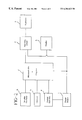
- FIG. 1 is a block diagram of an electronic circuit for controlling an appliance formed in accordance with the present invention.
- FIG. 2 is a block diagram of an electronic circuit including a variable oscillator for controlling an appliance formed in accordance with the present invention.
- FIG. 3 is a schematic diagram of a control circuit including a variable oscillator for controlling an appliance formed in accordance with the present invention.
- the present invention is directed to a control circuit and method for controlling appliances such as a fan, humidifier, or a heater in response to an external source. i.e., ambient temperature and/or humidity.
- the control circuit may be utilized in such appliances as disclosed in commonly owned U.S. Pat. Nos. 5,800,741 (wick filter humidifier), U.S. Pat. No. 5,792,390 (evaporative tank humidifier), U.S. Pat. No. 5,761,377 (radiant/forced air heater), U.S. Pat. No. 5,655,055 (space heater), U.S. Pat. No. 5,720,594 (oscillating fan) and U.S. Pat. No.5,660,605 (window fan), the disclosures of which are incorporated herein by reference.
- FIG. 1 A block diagram of an electronic control circuit formed in accordance with the present invention is illustrated in FIG. 1 .
- the electronic circuit includes the following: a power supply 1 , a microcontroller including an algorithm 2 , a sensor 3 , control switches 4 , a display indicator 5 , and a switching circuit 6 which is electrically connected to an appliance 7 .
- the control circuit includes control switches 4 which are electrically coupled to the microcontroller input ports and provide a means for setting and adjusting the appliance control target temperature and/or humidity.
- a sensor 3 is also provided which senses ambient temperature/humidity changes and provides this information to the microcontroller 2 .
- the microcontroller 2 includes an algorithm which analyzes the ambient temperature/humidity information provided by the sensor 3 and compares this information with the desired set point.
- the microcontroller 2 generates control signals in response to the input set point and measured ambient temperature/humidity for adjusting output of the appliance, e.g., motor speed of a fan or power to a heater element, to achieve and maintain the desired target temperature/humidity setting.
- the microcontroller 2 also controls a digital display 5 which is used to display either or both the actual sensed ambient temperature/humidity and the desired target temperature/humidity.
- the display 5 In operation, when the appliance is plugged in, the display 5 begins to flash and indicates a mode of operation and the present temperature/humidity reading provided by the sensor 3 .
- One of the control switches 4 may be in the form of a “Power/Mode” switch which allows the user to select a desired mode of operation, e.g. “Off/High/Low/Auto”.
- a desired mode of operation e.g. “Off/High/Low/Auto”.
- the “High” mode continuous maximum power is supplied to the fan or heater.
- the “Low” mode a reduced level of power, for example, approximately one half of maximum is continuously supplied to the fan or heater.
- the microcontroller's algorithm In both the “High” and “Low” manual operation modes, the microcontroller's algorithm is inactive and the appliance operates in a manual mode regardless of the target set temperature or humidity.
- the microcontroller 2 when the “Auto” mode is activated, the microcontroller 2 operates to control the appliance output based upon the sensed ambient temperature and/or humidity.
- the microcontroller analyzes information received from the sensor 3 and compares this information with a desired set point input through one or more “Set Point Adjust” control switches.
- the “Set Point Adjust” may be a single control switch which, when pressed, increases the set point by one or more increments until a maximum setting is reached at which point pressing the switch further returns the set point to its lowest setting.
- the “Set Point Adjust” may comprise two control switches which allow for up and down adjustment.
- the microcontroller's program reads the desired temperature/humidity level set by the control switches and compares this set point with the information received by the sensor 3 .
- the program of the microcontroller sends a signal to the switching circuit 6 to provide maximum power to the appliance.
- the microcontroller's program sends a signal to the switching circuit 6 to provide a reduced level of power, for example, approximately one-half maximum, to the appliance.
- the program sends a signal to the switching circuit to terminate power to the appliance.
- control circuit preferably further includes a variable oscillator 8 which incorporates the sensor 3 and an interrupt circuit 9 as shown in FIG. 2 .
- the variable oscillator 8 changes frequency in response to sensed ambient temperature/humidity changes and transfers this information to the microcontroller 2 .
- the microcontroller 2 preferably includes an algorithm which analyzes frequency changes of the variable oscillator and provides control signals for adjusting motor speed of a fan or power to a heater element to achieve and maintain the desired target temperature/humidity setting.
- An interrupt 9 is electrically coupled to the AC power line and generates an interrupt signal at each zero crossing of the 60 Hz cycle.
- a microcontroller counter is read and then set to zero and the microcontroller compares the value in the counter to a look-up table in the algorithm stored therein which includes related temperatures/humidity.
- the AC power line also provides a reference frequency for the microprocessor clock oscillator.
- the power supply circuit 1 includes a half-wave rectifier including diode D 1 and resistor R 3 .
- Diode D 1 and resistor R 3 are coupled to a 120 volts AC power source and convert the AC power source to a DC pulse.
- the power supply 1 provides approximately 5 volts DC to the control circuitry of FIG. 3.
- a zener diode D 2 is coupled to resistor R 3 and provides a 5 volt regulated DC supply to the control circuit.
- Filter capacitor C 2 is coupled to the zener diode D 2 to filter ripple from the DC supply to acceptable limits.
- the DC supply provides power to the microcontroller U 1 , transistor Q 2 , switch S 1 and switch S 2 .
- the control switch circuit 4 formed in accordance with the preferred embodiment of the present invention includes UP and DN push-buttons, S 1 and S 2 , to set and change the target temperature/humidity.
- the “Power/Mode” switch is not shown in FIG. 3.
- the switches S 1 , S 2 are preferably single-pole, single-throw momentary push-button switches which are electrically coupled to the power supply and the microcontroller.
- Switch S 1 is electrically coupled to a first microcontroller input port
- switch S 2 is electrically coupled to a second input port a target temperature/humidity is set by activating either switch S 1 for decreasing the set point or switch S 2 for increasing the set point.
- Switch S 1 and resistor R 5 are connected to the DC supply and a microcontroller input port, P 33 .
- switch S 1 When switch S 1 is open, the DC supply is applied to the microcontroller input.
- the microcontroller U 1 interprets this voltage as a high input and the algorithm does not respond.
- Closing switch S 1 pulls the DC supply to ground causing a low voltage to be applied to the microcontroller input P 33 .
- the low voltage is interpreted as a low applied to the microprocessor input.
- the algorithm responds to the low input by decreasing the set point.
- Resistor R 5 serves as a pull-up resistor to maintain a high value on the input when S 1 is not pressed.
- Switch S 2 and resistor R 6 operate identically to switch S 1 and resistor R 5 , except that switch S 2 and resistor R 6 are connected to microcontroller input P 32 and activating switch S 2 results in an increased set point.
- an interrupt line is coupled to the microcontroller and the AC power line through resistor R 1 .
- the interrupt signal is generated by the AC power line at each zero crossing of the 60 Hz sine wave cycle.
- the counter within the microcontroller is read and then set to zero by the interrupt generated by the zero crossing of the 60 Hz sine wave cycle.
- a variable clock oscillator 8 increments the counter within the microcontroller U 1 during each half cycle. Accordingly, the value in the counter at the next zero crossing of the 60 Hz sine wave cycle indicates how fast the clock oscillator is oscillating. Since the thermistor determines the oscillator frequency, the value in the counter can be related to temperature/humidity by means of a look-up table in the microcontroller algorithm.
- the illustrated switching circuit 6 is a high voltage switching circuit which electronically controls the AC power applied to the appliance.
- the switching circuit 6 receives a signal generated by the microcontroller and responds by applying continuously variable AC power to the appliance. More specifically, the switching circuit 6 is coupled to a microcontroller output port, P 27 and the appliance AC power line. Power to the appliance is controlled by triac Q 1 for a portion of the cycle of the 60 Hz sine wave cycle.
- Microcontroller U 1 controls the switching circuit by sending a control signal pulse to transistor Q 2 .
- Transistor Q 2 is coupled to triac Q 1 and controls the conducting state of triac Q 1 , i.e., on or off. Transistor Q 2 provides current gain to discharge capacitor C 3 into the gate of triac Q 1 .
- Triac Q 1 responds to transistor Q 2 by variably controlling the AC power application to the appliance.
- An algorithm in microcontroller U 1 varies the duty cycle of the control signal at the output port P 27 in relation to sensed temperature/humidity.
- the output signal provided at output port P 27 controls the switching rate of transistor Q 2 , while resistor R 9 limits the base current at transistor Q 2 .
- Capacitor C 3 is charged to VCC through resistor R 4 when transistor Q 2 is off a high level pulse on P 27 turns on transistor Q 2 causing a negative pulse to be applied to the gate of triac Q 1 . With either polarity of the AC line a negative pulse turns on triac Q 1 .
- the point in the AC sinewave where triac Q 1 is turned on determines the amount of power applied to the heater/fan. Since the triac Q 1 is being turned on when the line voltage is at some value other than zero volts, RFI is generated and must be filtered by capacitor C 1 to prevent it from being conducted by the line cord.
- the control circuit further includes a display circuit 5 .
- display U 2 is a multiplexed liquid crystal display which displays the actual ambient temperature/humidity as determined by the control circuit and the desired target temperature humidity.
- the display is driven by the microcontroller through output ports P 20 -P 26 .
- Control of display U 2 is achieved by a voltage divider network comprising of resistors R 7 , R 8 , R 10 , R 11 and microcontroller output ports P 00 -P 02 .
- Resistor R 7 is coupled to microcontroller port P 02 , display multiplex input 1 , and resistor R 10 .
- the second lead of resistor R 10 is coupled to microcontroller port P 00 .
- Resistor R 8 is coupled to microcontroller port P 01 , display multiplex input 2 , and resistor R 11 .
- the variable oscillator circuit 8 formed in accordance with the present invention is also illustrated in FIG. 3 .
- the variable oscillator is electrically coupled to the microcontroller and comprises a thermistor RT 1 , a capacitor C 4 , and a variable capacitor C 5 .
- the variable oscillator circuit 8 changes frequency in response to ambient temperature changes. These changes are sensed by the thermistor RT 1 and are monitored by the microcontroller U 1 . More specifically, the variable oscillator is connected to the oscillator in (OSC_IN) and the oscillator out (OSC_OUT) pins of the microcontroller. The frequency of the variable oscillator is set by the thermistor RT 1 and the capacitor C 5 .
- the resistance of the thermistor RT 1 changes.
- Thermistor RT 1 and capacitor C 5 form an R-C timing charge so that as the thermistor RT 1 resistance changes, the R-C time constant changes in accordance with temperature.
- the frequency of the variable oscillator varies in response to the changing R-C time constant which is monitored by the microcontroller.
- a variable capacitor C 4 is provided to compensate for part tolerances.
- the thermistor RT 1 may be replaced with a humidity sensitive device, such as a variable capacitor, to operate in the same way as described above.
- a humidity sensitive device such as a variable capacitor
- an advantage of this type of control circuit is that it does not use the I/O pins of the microprocessor, but rather uses the clock oscillator of the microprocessor which is essential for the microprocessor to function.
- Yet another distinct feature of the circuit is the use of the 50 or 60 Hz AC line as a precise time reference for measuring the oscillator frequency of the microprocessor.
- the controller circuit In operation of a fan for cooling, if the desired target control temperature is below the sensed ambient temperature as determined by the microcontroller by, for example, ten or more units, the controller circuit applies maximum power to the appliance. As the ambient temperature approaches the set point, the sensor responsive device, e.g. thermistor, senses the decrease in temperature and the controller responds by decreasing the power to the fan motor. As the ambient temperature approaches the desired target set point, the controller circuit further decreases the power to the fan motor. This continues until the set point is equal to the sensed ambient temperature, at which point the control circuit terminates power to the fan motor.
- the sensor responsive device e.g. thermistor
- the controller circuit In operation of a heater having a heater element, if the desired target set point is above the ambient temperature as determined by the microcontroller to be, for example, ten or more degrees, the controller circuit applies full maximum power to the heater. As the thermistor senses a decrease in the difference between the desired target temperature and the ambient temperature, the control circuit decreases the amount of power applied to the heater element, thereby decreasing heat output. The controller circuit applies continuously less power to the heater until the set control temperature equals the ambient temperature, at which point the control circuit terminates application of power to the heater.
- the ten degree temperature threshold may be set to any desired temperature range.
- An alternative embodiment may include a humidity sensing device that responds to changes in humidity.
- Humidifiers generally include either a wick filter and a fan for pulling outside air through the moistened wick filter to redistribute the moistened air into the environment or a heating element in thermal contact with an evaporative water tank for releasing evaporated water into the environment.
- the control circuit will apply maximum power to the fan.
- the humidity sensor e.g., a variable capacitive device
- the control circuit decreases the amount of power applied to the fan.
- the control circuit responds by applying less power to the fan.
- the control circuit shuts off the power to the fan.
- power is supplied to a heating element in thermal contact with a water tank to heat and thereby evaporate water into the environment.
- the present invention is also directed to a method of controlling appliances such as a fan, a heater, or a humidifier in response to an external source.
- a source may be a thermistor or a humidistat which is electrically connected to the variable oscillator of a microprocessor.
- the method includes controlling the frequency of the variable oscillator by an external source and generating a control signal in response to the changing frequency.
- the control signal is used to variably adjust power to the appliance.
- the method may include a means for altering a variable electrical device in response to ambient temperature and/or ambient humidity and controlling the frequency of a clock oscillator in a microprocessor in response to the device.
- the method includes calculating the ambient temperature and/or ambient humidity in the microprocessor in response to the frequency of the clock oscillator and generating a control signal in response to the calculated ambient temperature and/or ambient humidity.
- a counter in the microprocessor may be set in response to the frequency of the clock oscillator and the value in the counter may be compared to a value in a look-up table to determine ambient temperature and/or ambient humidity. From the calculated ambient temperature/humidity, a control signal may be sent to the appliance to control a number of variables, such as velocity of a fan or power to a motor or heater.
- variable oscillator is not limited to a variable resistive electrical device.
- the variable electrical device may include a variably changing capacitor or both a variable capacitive device and variable resistive device.
Abstract
Description
| PARTS LIST FOR THE ELECTRONIC CIRCUIT |
| ILLUSTRATED IN FIG. 3 |
| Resistor | 3.3M | R1 | ||
| Resistor | 10K, ½W | R3 | ||
| Resistor | 1K | R4 | ||
| Resistor | 100K | R5 | ||
| Resistor | 100K | R6 | ||
| Resistor | 100K | R7 | ||
| Resistor | 100K | R8 | ||
| Resistor | 1K | R9 | ||
| Resistor | 100K | R10 | ||
| Resistor | 100K | R11 | ||
| Capacitor | 0.001UF | C1 | ||
| Capacitor | 220UF | C2 | ||
| Capacitor | 1UF | C3 | ||
| Variable Capacitor | 4-20PF | C4 | ||
| Capacitor | 33PF | C5 | ||
| Diode | 1N4004 | D1 | ||
| Zener Diode | 4.7V, ½W | D2 | ||
| Triac | Q1 | |||
| Transistor | TO92EBC | Q2 | ||
| Thermistor | 203JG1Z | RT1 | ||
| Microcontroller | Z86C04PSC, Z86C08PSC | U1 | ||
| Display | LCD Dual 7Seg. | U2 | ||
| Switch | SPST Momentary Push-button | S1 | ||
| Switch | SPST Momentary Push-button | S2 | ||
| Fuse | PCB Trace | F1 | ||
Claims (23)
Priority Applications (1)
| Application Number | Priority Date | Filing Date | Title |
|---|---|---|---|
| US09/213,689 US6204623B1 (en) | 1998-12-17 | 1998-12-17 | Heater, humidifier or fan including a circuit for controlling the output thereof |
Applications Claiming Priority (1)
| Application Number | Priority Date | Filing Date | Title |
|---|---|---|---|
| US09/213,689 US6204623B1 (en) | 1998-12-17 | 1998-12-17 | Heater, humidifier or fan including a circuit for controlling the output thereof |
Publications (1)
| Publication Number | Publication Date |
|---|---|
| US6204623B1 true US6204623B1 (en) | 2001-03-20 |
Family
ID=22796116
Family Applications (1)
| Application Number | Title | Priority Date | Filing Date |
|---|---|---|---|
| US09/213,689 Expired - Lifetime US6204623B1 (en) | 1998-12-17 | 1998-12-17 | Heater, humidifier or fan including a circuit for controlling the output thereof |
Country Status (1)
| Country | Link |
|---|---|
| US (1) | US6204623B1 (en) |
Cited By (40)
| Publication number | Priority date | Publication date | Assignee | Title |
|---|---|---|---|---|
| US20020112725A1 (en) * | 1999-08-23 | 2002-08-22 | Mohammad Thudor | Humidity controller |
| US6470289B1 (en) * | 1999-08-05 | 2002-10-22 | Compaq Information Technologies Group, L.P. | Independently controlling passive and active cooling in a computer system |
| US20020166020A1 (en) * | 2001-05-04 | 2002-11-07 | Rlx Technologies, Inc. | Server Chassis Hardware master system and method |
| US6601168B1 (en) | 1999-11-19 | 2003-07-29 | Hewlett-Packard Development Company, L.P. | Computer fan speed system to reduce audible perceptibility of fan speed changes |
| US20040060713A1 (en) * | 2002-09-12 | 2004-04-01 | Brouwer Gerardus J. | Defective sod rejector and deflector |
| US6737824B1 (en) * | 2002-09-30 | 2004-05-18 | National Semiconductor Corporation | Fan acceleration control |
| US20040199797A1 (en) * | 2003-04-04 | 2004-10-07 | Vuong Vinh T. | Multiple source fan control with override |
| US20040227481A1 (en) * | 2003-05-12 | 2004-11-18 | Denso Corporation | Electric motor drive apparatus and motor-driven power steering system |
| US6826456B1 (en) * | 2001-05-04 | 2004-11-30 | Rlx Technologies, Inc. | System and method for controlling server chassis cooling fans |
| US6871300B1 (en) | 2001-05-04 | 2005-03-22 | Rlx Technologies, Inc. | Embedded server chassis hardware master system and method |
| US6873883B2 (en) | 2001-12-26 | 2005-03-29 | Hewlett-Packard Development Company, L.P. | Adaptive fan controller for a computer system |
| US20060049694A1 (en) * | 2004-09-03 | 2006-03-09 | Lawrence Kates | Method and apparatus for load management in an electric power system |
| US7075261B2 (en) * | 2002-04-10 | 2006-07-11 | Standard Microsystems Corporation | Method and apparatus for controlling a fan |
| US20070284361A1 (en) * | 2004-09-15 | 2007-12-13 | Hossein Nadjafizadeh | System and method for regulating a heating humidifier |
| US20070299562A1 (en) * | 2006-06-26 | 2007-12-27 | Lawrence Kates | Method and apparatus for temperature-based load management metering in an electric power system |
| US20080084640A1 (en) * | 2006-10-06 | 2008-04-10 | Perfect Union Co., Ltd. | Rotation speed controller for fans |
| US20090084776A1 (en) * | 2007-10-02 | 2009-04-02 | Chuan-Pan Huang | Induction device for a humidifier |
| US20090118870A1 (en) * | 2005-05-24 | 2009-05-07 | Nobuki Matsui | Humidity control system |
| US20090211986A1 (en) * | 2008-02-22 | 2009-08-27 | Lawrence Kates | Method and apparatus for energy-efficient temperature-based systems management |
| US20100010683A1 (en) * | 2008-07-14 | 2010-01-14 | Lawrence Kates | Method and apparatus for power-limiting electrical access |
| US20100078497A1 (en) * | 2008-09-29 | 2010-04-01 | Gasper Thomas P | Method of Dispensing a Volatile Material |
| US20100078498A1 (en) * | 2008-09-29 | 2010-04-01 | Gasper Thomas P | Method of Dispensing a Volatile Material |
| US20100078494A1 (en) * | 2008-10-01 | 2010-04-01 | Marco Mularoni | Humidity-activated ventilation system switch |
| US20100215510A1 (en) * | 2009-02-26 | 2010-08-26 | Chao-Ming Tsai | RPM Controller Using Drive Profiles |
| US20100283510A1 (en) * | 2009-05-11 | 2010-11-11 | Zhongshan Broad-Ocean Motor Co., Ltd. | Clock-detecting circuit |
| US7863849B2 (en) | 2008-02-29 | 2011-01-04 | Standard Microsystems Corporation | Delta-sigma modulator for a fan driver |
| US20110068190A1 (en) * | 2009-09-21 | 2011-03-24 | Gasper Thomas P | Methods of Emitting a Volatile Material from a Diffuser |
| CN102354233A (en) * | 2011-09-16 | 2012-02-15 | 苏州创泰电子有限公司 | Internet of things temperature controller |
| CN103207633A (en) * | 2013-03-07 | 2013-07-17 | 上海电机学院 | Temperature and humidity monitoring method and system |
| US20130261808A1 (en) * | 2012-03-30 | 2013-10-03 | John K. Besore | System and method for energy management of an hvac system |
| US20140062376A1 (en) * | 2012-08-31 | 2014-03-06 | Hubei Queen-Ocean Electrical Appliance Manufacture Co., Ltd. | Fan motor |
| US9186477B2 (en) | 1997-06-17 | 2015-11-17 | Fisher & Paykel Healthcare Limited | Humidity controller |
| WO2016101610A1 (en) * | 2014-12-25 | 2016-06-30 | 歌尔声学股份有限公司 | Environmental sensor and environmental parameter measurement and prediction method |
| US9976764B2 (en) | 2014-05-28 | 2018-05-22 | Leviton Manufacturing Co., Inc. | Apparatus and methods for controlling a ventilation mechanism |
| US10130787B2 (en) | 1997-06-17 | 2018-11-20 | Fisher & Paykel Healthcare Limited | Humidity controller |
| US10619863B2 (en) | 2018-08-03 | 2020-04-14 | Haier Us Appliance Solutions, Inc. | Cooking engagement system equipped with thermistor |
| US10627118B2 (en) | 2018-08-03 | 2020-04-21 | Haier Us Appliance Solutions, Inc. | Cooking engagement system equipped with humidity sensor |
| US10845246B2 (en) | 2018-08-03 | 2020-11-24 | Haier Us Appliance Solutions, Inc. | Cooking engagement system equipped with infrared sensor |
| US20210302068A1 (en) * | 2020-03-31 | 2021-09-30 | World & Main (Cranbury) LLC | PTC Heater with Energy Save Function |
| US20210303009A1 (en) * | 2020-03-31 | 2021-09-30 | World & Main (Cranbury) LLC | Heater with Energy Save Function |
Citations (17)
| Publication number | Priority date | Publication date | Assignee | Title |
|---|---|---|---|---|
| US4527247A (en) * | 1981-07-31 | 1985-07-02 | Ibg International, Inc. | Environmental control system |
| US5072597A (en) * | 1989-04-13 | 1991-12-17 | Motor Panels (Coventry) Ltd. | Control systems for automotive air conditioning systems |
| US5278936A (en) | 1991-12-23 | 1994-01-11 | Steve Shao | Thermostatically controlled portable electric space heater with automatic temperature setback for energy saving |
| US5410230A (en) * | 1992-05-27 | 1995-04-25 | General Electric Company | Variable speed HVAC without controller and responsive to a conventional thermostat |
| US5449319A (en) * | 1993-07-08 | 1995-09-12 | Steven D. Dushane | Dwelling heating and air conditioning system |
| US5457766A (en) * | 1992-05-23 | 1995-10-10 | Samsung Electronics Co., Ltd. | Fan speed control circuit |
| US5578753A (en) * | 1995-05-23 | 1996-11-26 | Micro Weiss Electronics, Inc. | Humidity and/or temperature control device |
| US5592989A (en) * | 1994-04-28 | 1997-01-14 | Landis & Gyr Powers, Inc. | Electronic thermostat having high and low voltage control capability |
| US5628199A (en) * | 1992-07-01 | 1997-05-13 | Gas Research Institute | Microprocessor-based controller |
| US5836691A (en) * | 1996-07-17 | 1998-11-17 | Techno Togo Limited Company | Method of thermometry and apparatus for the thermometry |
| US5911747A (en) * | 1997-09-19 | 1999-06-15 | Pentech Energy Solutions, Inc. | HVAC system control incorporating humidity and carbon monoxide measurement |
| US5943473A (en) * | 1997-05-29 | 1999-08-24 | Levine; Walter | Heated cartridge humidifier |
| US5945038A (en) * | 1998-08-07 | 1999-08-31 | Bemis Manufacturing Company | Humidifier wick assembly with float rod retainer |
| US5975502A (en) * | 1998-07-27 | 1999-11-02 | Emerson Electric Co. | Wick system for a humidifier and a method for operating the wick system |
| US5984663A (en) * | 1995-04-19 | 1999-11-16 | Bowin Technology Pty. Ltd. | Gas fueled heating appliance |
| US5984002A (en) * | 1994-09-01 | 1999-11-16 | Konica Corporation | Temperature and humidity control apparatus and temperature and humidity prediction apparatus used therefor |
| US5993312A (en) * | 1997-12-22 | 1999-11-30 | Case Corporation | Agricultural vehicle cab automatic temperature control system |
-
1998
- 1998-12-17 US US09/213,689 patent/US6204623B1/en not_active Expired - Lifetime
Patent Citations (17)
| Publication number | Priority date | Publication date | Assignee | Title |
|---|---|---|---|---|
| US4527247A (en) * | 1981-07-31 | 1985-07-02 | Ibg International, Inc. | Environmental control system |
| US5072597A (en) * | 1989-04-13 | 1991-12-17 | Motor Panels (Coventry) Ltd. | Control systems for automotive air conditioning systems |
| US5278936A (en) | 1991-12-23 | 1994-01-11 | Steve Shao | Thermostatically controlled portable electric space heater with automatic temperature setback for energy saving |
| US5457766A (en) * | 1992-05-23 | 1995-10-10 | Samsung Electronics Co., Ltd. | Fan speed control circuit |
| US5410230A (en) * | 1992-05-27 | 1995-04-25 | General Electric Company | Variable speed HVAC without controller and responsive to a conventional thermostat |
| US5628199A (en) * | 1992-07-01 | 1997-05-13 | Gas Research Institute | Microprocessor-based controller |
| US5449319A (en) * | 1993-07-08 | 1995-09-12 | Steven D. Dushane | Dwelling heating and air conditioning system |
| US5592989A (en) * | 1994-04-28 | 1997-01-14 | Landis & Gyr Powers, Inc. | Electronic thermostat having high and low voltage control capability |
| US5984002A (en) * | 1994-09-01 | 1999-11-16 | Konica Corporation | Temperature and humidity control apparatus and temperature and humidity prediction apparatus used therefor |
| US5984663A (en) * | 1995-04-19 | 1999-11-16 | Bowin Technology Pty. Ltd. | Gas fueled heating appliance |
| US5578753A (en) * | 1995-05-23 | 1996-11-26 | Micro Weiss Electronics, Inc. | Humidity and/or temperature control device |
| US5836691A (en) * | 1996-07-17 | 1998-11-17 | Techno Togo Limited Company | Method of thermometry and apparatus for the thermometry |
| US5943473A (en) * | 1997-05-29 | 1999-08-24 | Levine; Walter | Heated cartridge humidifier |
| US5911747A (en) * | 1997-09-19 | 1999-06-15 | Pentech Energy Solutions, Inc. | HVAC system control incorporating humidity and carbon monoxide measurement |
| US5993312A (en) * | 1997-12-22 | 1999-11-30 | Case Corporation | Agricultural vehicle cab automatic temperature control system |
| US5975502A (en) * | 1998-07-27 | 1999-11-02 | Emerson Electric Co. | Wick system for a humidifier and a method for operating the wick system |
| US5945038A (en) * | 1998-08-07 | 1999-08-31 | Bemis Manufacturing Company | Humidifier wick assembly with float rod retainer |
Cited By (62)
| Publication number | Priority date | Publication date | Assignee | Title |
|---|---|---|---|---|
| US9186477B2 (en) | 1997-06-17 | 2015-11-17 | Fisher & Paykel Healthcare Limited | Humidity controller |
| US10130787B2 (en) | 1997-06-17 | 2018-11-20 | Fisher & Paykel Healthcare Limited | Humidity controller |
| US6470289B1 (en) * | 1999-08-05 | 2002-10-22 | Compaq Information Technologies Group, L.P. | Independently controlling passive and active cooling in a computer system |
| US7106955B2 (en) * | 1999-08-23 | 2006-09-12 | Fisher & Paykel Healthcare Limited | Humidity controller |
| US20020112725A1 (en) * | 1999-08-23 | 2002-08-22 | Mohammad Thudor | Humidity controller |
| US6601168B1 (en) | 1999-11-19 | 2003-07-29 | Hewlett-Packard Development Company, L.P. | Computer fan speed system to reduce audible perceptibility of fan speed changes |
| US6934786B2 (en) | 2001-05-04 | 2005-08-23 | Rlx Technologies, Inc. | Server chassis hardware master system and method |
| US20020166020A1 (en) * | 2001-05-04 | 2002-11-07 | Rlx Technologies, Inc. | Server Chassis Hardware master system and method |
| US20050262392A1 (en) * | 2001-05-04 | 2005-11-24 | Rlx Technologies, Inc., A Delaware Corporation | Embedded server chassis hardware master system and method |
| US6826456B1 (en) * | 2001-05-04 | 2004-11-30 | Rlx Technologies, Inc. | System and method for controlling server chassis cooling fans |
| US6871300B1 (en) | 2001-05-04 | 2005-03-22 | Rlx Technologies, Inc. | Embedded server chassis hardware master system and method |
| US6873883B2 (en) | 2001-12-26 | 2005-03-29 | Hewlett-Packard Development Company, L.P. | Adaptive fan controller for a computer system |
| US7075261B2 (en) * | 2002-04-10 | 2006-07-11 | Standard Microsystems Corporation | Method and apparatus for controlling a fan |
| US20040060713A1 (en) * | 2002-09-12 | 2004-04-01 | Brouwer Gerardus J. | Defective sod rejector and deflector |
| US6737824B1 (en) * | 2002-09-30 | 2004-05-18 | National Semiconductor Corporation | Fan acceleration control |
| US20040199797A1 (en) * | 2003-04-04 | 2004-10-07 | Vuong Vinh T. | Multiple source fan control with override |
| US7196903B2 (en) | 2003-04-04 | 2007-03-27 | Hewlett-Packard Development Company, L.P. | Multiple source fan control with override |
| US20040227481A1 (en) * | 2003-05-12 | 2004-11-18 | Denso Corporation | Electric motor drive apparatus and motor-driven power steering system |
| US7164248B2 (en) * | 2003-05-12 | 2007-01-16 | Denso Corporation | Electric motor drive apparatus and motor-driven power steering system |
| US20060049694A1 (en) * | 2004-09-03 | 2006-03-09 | Lawrence Kates | Method and apparatus for load management in an electric power system |
| US9084865B2 (en) * | 2004-09-15 | 2015-07-21 | Covidien Ag | System and method for regulating a heating humidifier |
| JP4909898B2 (en) * | 2004-09-15 | 2012-04-04 | コビデイエン・アーゲー | Humidifier with device that adjusts the degree of humidification of airflow |
| JP2008513071A (en) * | 2004-09-15 | 2008-05-01 | マリンクロット デベロップメント フランス | Humidifier with device that adjusts the degree of humidification of airflow |
| US20070284361A1 (en) * | 2004-09-15 | 2007-12-13 | Hossein Nadjafizadeh | System and method for regulating a heating humidifier |
| US20090118870A1 (en) * | 2005-05-24 | 2009-05-07 | Nobuki Matsui | Humidity control system |
| US20090160267A1 (en) * | 2006-06-26 | 2009-06-25 | Lawrence Kates | Method and apparatus for temperature-based load management metering in an electric power system |
| US20070299562A1 (en) * | 2006-06-26 | 2007-12-27 | Lawrence Kates | Method and apparatus for temperature-based load management metering in an electric power system |
| US7450356B2 (en) * | 2006-10-06 | 2008-11-11 | Perfect Union Co., Ltd. | Rotation speed controller for fans |
| US20080084640A1 (en) * | 2006-10-06 | 2008-04-10 | Perfect Union Co., Ltd. | Rotation speed controller for fans |
| US20090084776A1 (en) * | 2007-10-02 | 2009-04-02 | Chuan-Pan Huang | Induction device for a humidifier |
| USRE46219E1 (en) | 2008-02-22 | 2016-11-29 | Google Inc. | Method and apparatus for energy-efficient temperature-based systems management |
| US20090211986A1 (en) * | 2008-02-22 | 2009-08-27 | Lawrence Kates | Method and apparatus for energy-efficient temperature-based systems management |
| US8014902B2 (en) | 2008-02-22 | 2011-09-06 | Lawrence Kates | Method and apparatus for energy-efficient temperature-based systems management |
| US7863849B2 (en) | 2008-02-29 | 2011-01-04 | Standard Microsystems Corporation | Delta-sigma modulator for a fan driver |
| US20100010683A1 (en) * | 2008-07-14 | 2010-01-14 | Lawrence Kates | Method and apparatus for power-limiting electrical access |
| US8293172B2 (en) | 2008-09-29 | 2012-10-23 | S.C. Johnson & Son, Inc. | Method of dispensing a volatile material |
| US20100078498A1 (en) * | 2008-09-29 | 2010-04-01 | Gasper Thomas P | Method of Dispensing a Volatile Material |
| US20100078497A1 (en) * | 2008-09-29 | 2010-04-01 | Gasper Thomas P | Method of Dispensing a Volatile Material |
| US8197762B2 (en) | 2008-09-29 | 2012-06-12 | S.C. Johnson & Son, Inc. | Method of dispensing a volatile material |
| US20100078494A1 (en) * | 2008-10-01 | 2010-04-01 | Marco Mularoni | Humidity-activated ventilation system switch |
| US20100215510A1 (en) * | 2009-02-26 | 2010-08-26 | Chao-Ming Tsai | RPM Controller Using Drive Profiles |
| US9212664B2 (en) | 2009-02-26 | 2015-12-15 | Standard Microsystems Corporation | RPM controller using drive profiles |
| US8241008B2 (en) | 2009-02-26 | 2012-08-14 | Standard Microsystems Corporation | RPM controller using drive profiles |
| US20100283510A1 (en) * | 2009-05-11 | 2010-11-11 | Zhongshan Broad-Ocean Motor Co., Ltd. | Clock-detecting circuit |
| US8854031B2 (en) * | 2009-05-11 | 2014-10-07 | Zhongshan Broad-Ocean Motor Co., Ltd. | Clock-detecting circuit |
| US9669125B2 (en) | 2009-09-21 | 2017-06-06 | S. C. Johnson & Son, Inc. | Methods of emitting a volatile material from a diffuser |
| US20110068190A1 (en) * | 2009-09-21 | 2011-03-24 | Gasper Thomas P | Methods of Emitting a Volatile Material from a Diffuser |
| CN102354233A (en) * | 2011-09-16 | 2012-02-15 | 苏州创泰电子有限公司 | Internet of things temperature controller |
| US20130261808A1 (en) * | 2012-03-30 | 2013-10-03 | John K. Besore | System and method for energy management of an hvac system |
| US20140062376A1 (en) * | 2012-08-31 | 2014-03-06 | Hubei Queen-Ocean Electrical Appliance Manufacture Co., Ltd. | Fan motor |
| US9276514B2 (en) * | 2012-08-31 | 2016-03-01 | Zhongshan Broad-Ocean Motor Co., Ltd. | Fan motor |
| CN103207633A (en) * | 2013-03-07 | 2013-07-17 | 上海电机学院 | Temperature and humidity monitoring method and system |
| CN103207633B (en) * | 2013-03-07 | 2015-11-25 | 上海电机学院 | A kind of temperature and humidity monitor method and system |
| US9976764B2 (en) | 2014-05-28 | 2018-05-22 | Leviton Manufacturing Co., Inc. | Apparatus and methods for controlling a ventilation mechanism |
| US11015831B2 (en) | 2014-05-28 | 2021-05-25 | Leviton Manufacturing Co., Inc. | Apparatus and methods for controlling a ventilation mechanism |
| WO2016101610A1 (en) * | 2014-12-25 | 2016-06-30 | 歌尔声学股份有限公司 | Environmental sensor and environmental parameter measurement and prediction method |
| US10317355B2 (en) | 2014-12-25 | 2019-06-11 | Goertek Inc. | Environmental sensor and method for measuring and predicting environmental parameters |
| US10619863B2 (en) | 2018-08-03 | 2020-04-14 | Haier Us Appliance Solutions, Inc. | Cooking engagement system equipped with thermistor |
| US10627118B2 (en) | 2018-08-03 | 2020-04-21 | Haier Us Appliance Solutions, Inc. | Cooking engagement system equipped with humidity sensor |
| US10845246B2 (en) | 2018-08-03 | 2020-11-24 | Haier Us Appliance Solutions, Inc. | Cooking engagement system equipped with infrared sensor |
| US20210302068A1 (en) * | 2020-03-31 | 2021-09-30 | World & Main (Cranbury) LLC | PTC Heater with Energy Save Function |
| US20210303009A1 (en) * | 2020-03-31 | 2021-09-30 | World & Main (Cranbury) LLC | Heater with Energy Save Function |
Similar Documents
| Publication | Publication Date | Title |
|---|---|---|
| US6204623B1 (en) | Heater, humidifier or fan including a circuit for controlling the output thereof | |
| US7573220B2 (en) | Self calibrating fan | |
| US4302663A (en) | Control system for a heater | |
| US5847526A (en) | Microprocessor controlled fan | |
| US4759498A (en) | Thermostatic control without temperature droop using duty cycle control | |
| US4777350A (en) | Heater with duty cycle controller | |
| GB2073455A (en) | Electrical power control systems | |
| US4817705A (en) | Thermostatic control without temperature droop using duty cycle control | |
| US4703886A (en) | Heat/cool comfort controller | |
| US20030225542A1 (en) | Electronic fan capable of automatic fan speed adjustment according to ambient temperature conditions | |
| US4072268A (en) | Heating control system | |
| US4291543A (en) | Temperature regulator for household appliances | |
| US5231848A (en) | Refrigerator cold control | |
| JPS61217648A (en) | Air temperature control device | |
| US4914925A (en) | Control device for an air conditioner | |
| KR100193706B1 (en) | Refrigerator load driving method and device | |
| KR20060114929A (en) | Control circuit for running a heater of electric home appliances | |
| KR930006378B1 (en) | Burner motor control device and method for oil burner | |
| JP2786883B2 (en) | Hair dryer | |
| KR100514002B1 (en) | Heating control apparatus and method comprising reservation function | |
| JPH0240886Y2 (en) | ||
| JPS5830512B2 (en) | I'm not sure what to do. | |
| KR900000527B1 (en) | Humidifier | |
| KR0151558B1 (en) | Method for controlling the amount of humidity of ultrasonic heating type humidifier | |
| US20190368764A1 (en) | Method and system for controlling distribution of thermally altered fluids |
Legal Events
| Date | Code | Title | Description |
|---|---|---|---|
| AS | Assignment |
Owner name: HOLMES PRODUCTS, CORP., MASSACHUSETTS Free format text: ASSIGNMENT OF ASSIGNORS INTEREST;ASSIGNORS:LEVY, WILLIAM;SHERWOOD, ROBERT A.;POLONCHAK, JOHN C.;REEL/FRAME:009741/0067;SIGNING DATES FROM 19881230 TO 19990112 |
|
| AS | Assignment |
Owner name: HOLMES GROUP, INC.,THE, MASSACHUSETTS Free format text: CHANGE OF NAME;ASSIGNOR:HOLMES PRODUCTS, CORP.;REEL/FRAME:011487/0552 Effective date: 19991123 |
|
| STCF | Information on status: patent grant |
Free format text: PATENTED CASE |
|
| FPAY | Fee payment |
Year of fee payment: 4 |
|
| AS | Assignment |
Owner name: GENERAL ELECTRIC CAPITAL CORPORATION, AS COLLATERA Free format text: SECURITY AGREEMENT;ASSIGNOR:HOLMES GROUP, INC. THE;REEL/FRAME:015065/0681 Effective date: 20040506 |
|
| FPAY | Fee payment |
Year of fee payment: 8 |
|
| AS | Assignment |
Owner name: JCS/THG, LLC, MASSACHUSETTS Free format text: MERGER;ASSIGNOR:THE HOLMES GROUP, INC.;REEL/FRAME:025137/0295 Effective date: 20050718 Owner name: SUNBEAM PRODUCTS, INC., FLORIDA Free format text: MERGER;ASSIGNOR:JCS/THG, LLC;REEL/FRAME:025137/0306 Effective date: 20060630 |
|
| AS | Assignment |
Owner name: BARCLAYS BANK PLC, AS ADMINISTRATIVE AGENT, NEW YO Free format text: PATENT SECURITY AGREEMENT;ASSIGNOR:SUNBEAM PRODUCTS, INC.;REEL/FRAME:025169/0465 Effective date: 20101007 |
|
| AS | Assignment |
Owner name: SUNBEAM PRODUCTS, INC., FLORIDA Free format text: TERMINATION AND RELEASE OF SECURITY INTEREST (RELEASES RF 025169/0465);ASSIGNOR:BARCLAYS BANK PLC;REEL/FRAME:026461/0935 Effective date: 20110531 Owner name: THE HOLMES GROUP, INC., MASSACHUSETTS Free format text: RELEASE OF SECURITY INTEREST (RELEASES RF 015065/0681);ASSIGNOR:GENERAL ELECTRIC CAPITAL CORPORATION;REEL/FRAME:026463/0499 Effective date: 20050718 |
|
| FPAY | Fee payment |
Year of fee payment: 12 |