US6202017B1 - Circuit configuration for controlling electric or electromechanical consumers - Google Patents
Circuit configuration for controlling electric or electromechanical consumers Download PDFInfo
- Publication number
- US6202017B1 US6202017B1 US07/989,027 US98902793A US6202017B1 US 6202017 B1 US6202017 B1 US 6202017B1 US 98902793 A US98902793 A US 98902793A US 6202017 B1 US6202017 B1 US 6202017B1
- Authority
- US
- United States
- Prior art keywords
- driver units
- signals
- braking pressure
- control unit
- pressure control
- Prior art date
- Legal status (The legal status is an assumption and is not a legal conclusion. Google has not performed a legal analysis and makes no representation as to the accuracy of the status listed.)
- Expired - Fee Related
Links
- 230000001360 synchronised effect Effects 0.000 claims abstract description 4
- 230000006399 behavior Effects 0.000 claims description 14
- 238000012544 monitoring process Methods 0.000 claims description 11
- 230000007257 malfunction Effects 0.000 claims description 6
- 230000004913 activation Effects 0.000 claims description 2
- 238000001514 detection method Methods 0.000 claims 2
- 230000001276 controlling effect Effects 0.000 description 3
- 230000007547 defect Effects 0.000 description 3
- 238000011156 evaluation Methods 0.000 description 2
- 238000004519 manufacturing process Methods 0.000 description 2
- 239000000725 suspension Substances 0.000 description 2
- 230000004308 accommodation Effects 0.000 description 1
- 230000003213 activating effect Effects 0.000 description 1
- 230000000712 assembly Effects 0.000 description 1
- 238000000429 assembly Methods 0.000 description 1
- 238000010586 diagram Methods 0.000 description 1
- 230000002093 peripheral effect Effects 0.000 description 1
- 230000001105 regulatory effect Effects 0.000 description 1
Images

Classifications
-
- B—PERFORMING OPERATIONS; TRANSPORTING
- B60—VEHICLES IN GENERAL
- B60T—VEHICLE BRAKE CONTROL SYSTEMS OR PARTS THEREOF; BRAKE CONTROL SYSTEMS OR PARTS THEREOF, IN GENERAL; ARRANGEMENT OF BRAKING ELEMENTS ON VEHICLES IN GENERAL; PORTABLE DEVICES FOR PREVENTING UNWANTED MOVEMENT OF VEHICLES; VEHICLE MODIFICATIONS TO FACILITATE COOLING OF BRAKES
- B60T8/00—Arrangements for adjusting wheel-braking force to meet varying vehicular or ground-surface conditions, e.g. limiting or varying distribution of braking force
- B60T8/32—Arrangements for adjusting wheel-braking force to meet varying vehicular or ground-surface conditions, e.g. limiting or varying distribution of braking force responsive to a speed condition, e.g. acceleration or deceleration
- B60T8/88—Arrangements for adjusting wheel-braking force to meet varying vehicular or ground-surface conditions, e.g. limiting or varying distribution of braking force responsive to a speed condition, e.g. acceleration or deceleration with failure responsive means, i.e. means for detecting and indicating faulty operation of the speed responsive control means
- B60T8/885—Arrangements for adjusting wheel-braking force to meet varying vehicular or ground-surface conditions, e.g. limiting or varying distribution of braking force responsive to a speed condition, e.g. acceleration or deceleration with failure responsive means, i.e. means for detecting and indicating faulty operation of the speed responsive control means using electrical circuitry
-
- B—PERFORMING OPERATIONS; TRANSPORTING
- B60—VEHICLES IN GENERAL
- B60T—VEHICLE BRAKE CONTROL SYSTEMS OR PARTS THEREOF; BRAKE CONTROL SYSTEMS OR PARTS THEREOF, IN GENERAL; ARRANGEMENT OF BRAKING ELEMENTS ON VEHICLES IN GENERAL; PORTABLE DEVICES FOR PREVENTING UNWANTED MOVEMENT OF VEHICLES; VEHICLE MODIFICATIONS TO FACILITATE COOLING OF BRAKES
- B60T2270/00—Further aspects of brake control systems not otherwise provided for
- B60T2270/40—Failsafe aspects of brake control systems
- B60T2270/408—Hierarchical failure detection
-
- B—PERFORMING OPERATIONS; TRANSPORTING
- B60—VEHICLES IN GENERAL
- B60T—VEHICLE BRAKE CONTROL SYSTEMS OR PARTS THEREOF; BRAKE CONTROL SYSTEMS OR PARTS THEREOF, IN GENERAL; ARRANGEMENT OF BRAKING ELEMENTS ON VEHICLES IN GENERAL; PORTABLE DEVICES FOR PREVENTING UNWANTED MOVEMENT OF VEHICLES; VEHICLE MODIFICATIONS TO FACILITATE COOLING OF BRAKES
- B60T2270/00—Further aspects of brake control systems not otherwise provided for
- B60T2270/40—Failsafe aspects of brake control systems
- B60T2270/414—Power supply failure
Definitions
- This invention relates to a circuit configuration for controlling a major number of electric or electromechanical consumers such as the electrically driven hydraulic pumps, the electromagnetically operable multi-directional valves etc. of an automotive vehicle control system where the control signals are generated by means of a control unit, such as a microprocessor or microcomputer, and can be delivered to the consumers via amplifier stages.
- a control unit such as a microprocessor or microcomputer
- Such control circuits are needed for anti-lock control systems, traction slip control systems and for suspension control systems.
- German Published Patent Application (DE-OS) No. 32 34 637 discloses a circuit configuration of this type for controlling an anti-lock-controlled brake system.
- Microprocessors or microcontrollers serve to derive braking pressure control signals from sensor signals containing the required information.
- the output signals of the microprocessors are delivered to electromagnetically operable valves influencing the pressure medium flow and, hence, the braking pressure.
- valve drivers or amplifier stages are actuated in parallel by the microcomputer via an interface module or via discrete electronic systems. This implies a considerable amount of wiring, all the more so since there are additional actuating and feedback lines in each case.
- the amplifier stages are designed as so-called “intelligent” power drivers and essentially consist of a power amplifier with integrated electronic controls and monitors.
- the amplifier stages of the present invention are interconnected as well as, via a synchronous serial interface, connected to the control unit so that a data transfer flows in a closed loop or chain from the control unit, via the amplifier stages and back to a serial entry of the control unit, for controlling the data transfer connections of an operating cycle and an activation instruction or a transfer instruction.
- the described disadvantages of known circuit configurations of this type are overcome.
- the amount of manufacturing cost is reduced by means of the special design of the power ICs and by a serial data transfer via the amplifier stages interconnected to form a closed loop. Data are transferred back to a serial entry of the control unit via this loop.
- the comparison of the serial output signals of the control unit with the input signals of this control unit allows conclusions with regard to proper operation of all the circuits.
- the amplifier stages for receiving and transferring the data to the following amplifier stages or back to the control unit are equipped with shift registers.
- each of the amplifier stages are assigned a position in the serial data word by means of which data transfer takes place from the control unit via the closed loop formed by the amplifier stages.
- a further example of an embodiment of this invention consists in that each of the amplifier stages is equipped with a nominal value memory.
- the instructions stored in the shift register are transferrable into the nominal value memory by means of a common transfer instruction and are implementable by means of corresponding actuation of the power amplifiers.
- rate the circuit configuration such as to ensure that, by means of the common transfer instruction, the actual values are transferrable into the shift registers and get back from the same to the control unit during data transfer in the closed loop. Evaluation of the actual values permits the existence of any defects to be directly detected.
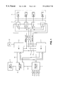
- FIG. 1 shows the principles of the structure and the essential assemblies of a circuit configuration according to this invention.
- FIG. 2 in a block diagram, shows the principles of the structure of an example of an embodiment of an amplifier stage of the circuit configuration according to FIG. 1 .
- the circuit configuration of FIG. 1 forms part of an electronic anti-lock control system. It serves for evaluating the information which wheel sensors S 1 -S 4 have obtained on the rotational behavior of the individual vehicle wheels and for generating braking pressure control signals by means of which electromagnetically operable multi-directional valves MWV 1 -MWVn are actuated. As is known, by means of these valves, the braking pressure in the wheel brakes is controlled or regulated in dependence on the rotational behavior of the wheels. Thus, it is possible to prevent the wheels from locking while, nevertheless, maintaining a braking pressure as high as possible in order to achieve an effective braking operation with a short stopping distance.
- the essential components of the illustrated circuit configuration are a trigger circuit 1 , where the output signals of the wheel sensors S 1 -S 4 are handled and converted, and two microcomputers 2 , 3 for generating braking pressure control signals. These signals are fed to amplifier stages VS 1 -VSn which, as a whole, are referred to by reference numeral 4 .
- the amplifier stages in dependence on the output signals of the microcomputers 2 , 3 , generate actuating signals for the multi-directional valves MWV 1 -MWVn combined into a block 5 .
- a monitoring circuit 6 is provided which, by means of a relay circuit 7 or the like, will interrupt power supply if a malfunction is detected, thus cutting off anti-lock control. Thereby, in a manner known, it is ensured even in case of defects in the electronic system that the brake will go on operating, if uncontrolled.
- the sensor signals handled in the trigger circuit 1 are processed and evaluated in the same way in the two microcomputers 2 , 3 .
- the data are permanently exchanged between the two microcomputers 2 , 3 via signal lines 8 , 9 and are checked for consistency. If they are not consistent this will be communicated to the monitoring circuit 6 via lines 10 and 11 , said monitoring circuit 6 thereupon activating cutoff of control via stage 7 . Even a defect in trigger circuit 1 will be communicated to the alarm circuit via line 12 and will cause cutoff of control.
- a clock generator 13 is represented, delivering the operating cycle of the microcomputers 2 , 3 and, via line 14 , to the amplifier stages 4 .
- Essential for this invention is the design and actuation of the individual amplifier stages VS 1 -VSn.
- These amplifier stages namely are designed as so-called “intelligent power drivers” and, on principle, consist of a power amplifier with integrated electronic controls and monitors.
- One sole chip, or rather one integrated circuit accommodates one, two or three power amplifiers of this type at a time.
- the number of the required amplifier stages, or rather of the required chips is determined by the number of the consumers connected.
- FIG. 1 only the electromagnetically operable multi-directional valves of an anti-lock control system are represented as consumers. However, it is also possible, for instance, to actuate the hydraulic pump of an anti-lock control system or of a suspension control system or even other consumers via these amplifier stages.
- the individual amplifier stages VS 1 -VSn of block 4 are connected in series with regard to data transfer and connected to a serial outlet of the microcomputer 2 (3) or, to put it in more general terms, are linked with the microcomputer 2 (3) via a synchronous serial interface. Data transfer is performed in the form of a closed loop or chain. The last link of this chain, the outlet of amplifier stage VSn, is led back to a serial entry of the microcomputer 2 (3).
- Information in the form of data words is available at the serial outlet of microcomputer 2 (3).
- the assignment of the individual amplifier stages is selected so as to ensure that each of the amplifier stages VS 1 -VSn is assigned a position in the serial data word by means of which data transfer is performed from the microcomputers to the amplifier stages.
- the individual amplifier stages contain shift registers 16 (see FIG. 2) which receive and transfer the signals in the operating cycle clk. As the loop is a closed loop, with the following transfer of a data word, the data are shifted back into the control unit, in this case, the microcomputer 2 (3).
- the individual amplifiers are serially connected into the data flow. Moreover, they are connected in parallel to the operating cycle or clk via a line 14 and are connected in parallel to a line 15 supplying a common transfer instruction. After the data have been written into the shift registers of the individual amplifier stages by means of a common instruction via line 15 , the respective signal is transferred into a nominal value memory 17 of the amplifier stages, and the instruction is carried out by means of corresponding actuation of the consumers 5 . This will subsequently be explained in more detail with reference to FIG. 2 .
- FIG. 2 serves to illustrate the mode of operation of the individual amplifier stages VS 1 -VSn.
- each amplifier stage contains a shift register 16 .
- the transfer instruction By means of the transfer instruction, the contents of this shift register are transferred into a nominal value memory 17 which by actuating a power transistor 18 directly carries out the instruction, with the power transistor 18 on its part being connected with the consumer such as a solenoid valve via a connection V.
- each of the amplifier stages contains an actual value memory 19 which, after the instructions have been carried out, registers the actual state of the power transistor 18 by means of a voltage monitoring circuit 20 and transfers the same into the shift register 16 with the next storage pulse.
- the inventive circuit configuration has many advantages as compared with the already described known circuit configurations with parallel actuation of the individual amplifier stages.
- the reduced amount of wiring proves to be a great advantage both in case of a compact structure of a complete control unit and in case of peripheral accommodation of the individual components. It is absolutely possible to accommodate the individual amplifiers, connected in series, at a large distance with regard to one another.
- the closed serial loop permits reliable monitoring. Therefore a system provided with such a circuit configuration is especially reliable in its operation. It is possible to connect whatever number of amplifier stages in series which will be sufficient for any cases coming up in practice.
Abstract
Description
Claims (13)
Applications Claiming Priority (3)
| Application Number | Priority Date | Filing Date | Title |
|---|---|---|---|
| DE4028926 | 1990-09-12 | ||
| DE4028926A DE4028926A1 (en) | 1990-09-12 | 1990-09-12 | CIRCUIT ARRANGEMENT FOR CONTROLLING ELECTRICAL OR ELECTROMECHANICAL CONSUMERS |
| PCT/EP1991/001516 WO1992004217A1 (en) | 1990-09-12 | 1991-08-09 | Circuit for the control of electrical or electromechanical consumers |
Publications (1)
| Publication Number | Publication Date |
|---|---|
| US6202017B1 true US6202017B1 (en) | 2001-03-13 |
Family
ID=6414105
Family Applications (1)
| Application Number | Title | Priority Date | Filing Date |
|---|---|---|---|
| US07/989,027 Expired - Fee Related US6202017B1 (en) | 1990-09-12 | 1991-08-09 | Circuit configuration for controlling electric or electromechanical consumers |
Country Status (5)
| Country | Link |
|---|---|
| US (1) | US6202017B1 (en) |
| EP (1) | EP0550451B1 (en) |
| JP (1) | JP3298878B2 (en) |
| DE (2) | DE4028926A1 (en) |
| WO (1) | WO1992004217A1 (en) |
Cited By (3)
| Publication number | Priority date | Publication date | Assignee | Title |
|---|---|---|---|---|
| US6379164B1 (en) * | 2000-05-08 | 2002-04-30 | Ronald G. Cash, Jr. | System and method for configuring electrical receptacles |
| US6514652B2 (en) | 2000-05-08 | 2003-02-04 | Ronald G. Cash, Jr. | Smart modular receptacle and system |
| US11498541B2 (en) * | 2015-11-12 | 2022-11-15 | Faiveley Transport Italia S.P.A. | Vehicle braking assembly |
Families Citing this family (5)
| Publication number | Priority date | Publication date | Assignee | Title |
|---|---|---|---|---|
| DE4233268A1 (en) * | 1992-10-02 | 1994-04-07 | Bayerische Motoren Werke Ag | Associating controller with sensors or actuators e.g. for motor vehicle level regulation system - successively polling outputs from controller while monitoring sequence of activation and responses of sensors associated with magnetically-controlled hydraulic cylinders to learn association |
| DE4312616A1 (en) * | 1993-04-19 | 1994-10-20 | Abb Patent Gmbh | Device for data transmission via an installation bus system |
| DE4313532B4 (en) * | 1993-04-24 | 2007-08-30 | Robert Bosch Gmbh | Method for checking an output stage |
| DE4314058A1 (en) * | 1993-04-29 | 1994-11-03 | Bayerische Motoren Werke Ag | interface |
| DE102009029642A1 (en) * | 2009-09-21 | 2011-03-24 | Robert Bosch Gmbh | Method for processing information and activities in a control and / or regulation system |
Citations (13)
| Publication number | Priority date | Publication date | Assignee | Title |
|---|---|---|---|---|
| FR2377308A1 (en) | 1977-01-13 | 1978-08-11 | Wabco Westinghouse Gmbh | PROCEDURE AND ASSEMBLY OF FUNCTIONAL CONTROL OF ANTI-LOCK REGULATION EQUIPMENT |
| US4255789A (en) * | 1978-02-27 | 1981-03-10 | The Bendix Corporation | Microprocessor-based electronic engine control system |
| US4347563A (en) * | 1980-06-16 | 1982-08-31 | Forney Engineering Company | Industrial control system |
| DE3136944A1 (en) | 1981-09-17 | 1983-03-31 | Wabco Westinghouse Fahrzeugbremsen GmbH, 3000 Hannover | Safety circuit in an antilock brake system |
| DE3234637A1 (en) | 1982-09-18 | 1984-03-22 | Alfred Teves Gmbh, 6000 Frankfurt | METHOD AND CIRCUIT FOR CONTROLLING A BRAKE-SLIP CONTROL SYSTEM |
| EP0133381A2 (en) | 1983-08-09 | 1985-02-20 | Nippondenso Co., Ltd. | Antiskid control with wheel-speed difference compensation |
| DE3447449A1 (en) | 1983-12-31 | 1985-07-11 | PCB Controls PLC, Blackrock, County Dublin | ELECTRONIC CONTROL UNIT FOR AN ANTI-BLOCKING SYSTEM |
| US4894781A (en) * | 1986-10-02 | 1990-01-16 | Nippondenso Co., Ltd. | Communication control system |
| US4926332A (en) * | 1985-07-22 | 1990-05-15 | Aisin Seiki Kabushiki Kaisha | Locking device for vehicles |
| US4933862A (en) * | 1987-02-23 | 1990-06-12 | Mitsubishi Denki Kabushiki Kaisha | Engine control apparatus |
| US4991101A (en) * | 1987-06-19 | 1991-02-05 | Diesel Kiki Co., Ltd. | Data communication control system |
| US5189617A (en) * | 1989-10-27 | 1993-02-23 | Hitachi, Ltd. | Motor vehicle control system and control unit therefor |
| US5327343A (en) * | 1990-09-01 | 1994-07-05 | Daimler-Benz Ag | Universally and bidirectionally operable device for signal path control in a motor vehicle diagnostic system |
Family Cites Families (11)
| Publication number | Priority date | Publication date | Assignee | Title |
|---|---|---|---|---|
| DE2338882C2 (en) * | 1973-08-01 | 1984-05-24 | Robert Bosch Gmbh, 7000 Stuttgart | Method and telecontrol system for switching electrical consumers on and off |
| JPS5049586A (en) * | 1973-09-03 | 1975-05-02 | ||
| DE2503679C2 (en) * | 1975-01-30 | 1983-01-27 | Robert Bosch Gmbh, 7000 Stuttgart | Telecontrol system for the selective control of consumers, in particular in motor vehicles |
| DE2557930A1 (en) * | 1975-12-22 | 1977-06-30 | Bosch Gmbh Robert | Analogue signals transmission system - uses increment generator for generation of pulses proportional to analogue signal |
| DE3139421A1 (en) * | 1981-10-03 | 1983-04-21 | Nsm-Apparatebau Gmbh & Co Kg, 6530 Bingen | Serial output circuit |
| DE3546662C3 (en) * | 1985-02-22 | 1997-04-03 | Bosch Gmbh Robert | Method for operating a data processing system |
| DE3603751A1 (en) * | 1986-02-06 | 1987-08-13 | Siemens Ag | INFORMATION TRANSFER SYSTEM FOR THE TRANSFER OF BINARY INFORMATION |
| EP0267468A3 (en) * | 1986-11-10 | 1989-10-11 | VEB Elektroprojekt und Anlagenbau Berlin | Method and circuit arrangement for information transmission between a central control device and peripheral units |
| DE3730468A1 (en) * | 1987-09-08 | 1989-03-16 | Bergmann Kabelwerke Ag | ON-BOARD NETWORK FOR MOTOR VEHICLES AND METHOD FOR OPERATING THE ON-BOARD NETWORK |
| DE3807418A1 (en) * | 1988-03-07 | 1989-09-21 | Bayerische Motoren Werke Ag | DATA BUS FOR MOTOR VEHICLES |
| DE3920122A1 (en) * | 1989-06-20 | 1991-01-10 | Sick Erwin Gmbh | Interrogation of number of status sensors - using common serial data transmission line for input and output |
-
1990
- 1990-09-12 DE DE4028926A patent/DE4028926A1/en not_active Ceased
-
1991
- 1991-08-09 US US07/989,027 patent/US6202017B1/en not_active Expired - Fee Related
- 1991-08-09 EP EP91914511A patent/EP0550451B1/en not_active Expired - Lifetime
- 1991-08-09 JP JP51386791A patent/JP3298878B2/en not_active Expired - Fee Related
- 1991-08-09 DE DE59104910T patent/DE59104910D1/en not_active Expired - Lifetime
- 1991-08-09 WO PCT/EP1991/001516 patent/WO1992004217A1/en active IP Right Grant
Patent Citations (14)
| Publication number | Priority date | Publication date | Assignee | Title |
|---|---|---|---|---|
| FR2377308A1 (en) | 1977-01-13 | 1978-08-11 | Wabco Westinghouse Gmbh | PROCEDURE AND ASSEMBLY OF FUNCTIONAL CONTROL OF ANTI-LOCK REGULATION EQUIPMENT |
| US4255789A (en) * | 1978-02-27 | 1981-03-10 | The Bendix Corporation | Microprocessor-based electronic engine control system |
| US4347563A (en) * | 1980-06-16 | 1982-08-31 | Forney Engineering Company | Industrial control system |
| DE3136944A1 (en) | 1981-09-17 | 1983-03-31 | Wabco Westinghouse Fahrzeugbremsen GmbH, 3000 Hannover | Safety circuit in an antilock brake system |
| US4546437A (en) | 1982-09-18 | 1985-10-08 | Itt Industries, Inc. | Method and circuit for the control of a brake slip control apparatus |
| DE3234637A1 (en) | 1982-09-18 | 1984-03-22 | Alfred Teves Gmbh, 6000 Frankfurt | METHOD AND CIRCUIT FOR CONTROLLING A BRAKE-SLIP CONTROL SYSTEM |
| EP0133381A2 (en) | 1983-08-09 | 1985-02-20 | Nippondenso Co., Ltd. | Antiskid control with wheel-speed difference compensation |
| DE3447449A1 (en) | 1983-12-31 | 1985-07-11 | PCB Controls PLC, Blackrock, County Dublin | ELECTRONIC CONTROL UNIT FOR AN ANTI-BLOCKING SYSTEM |
| US4926332A (en) * | 1985-07-22 | 1990-05-15 | Aisin Seiki Kabushiki Kaisha | Locking device for vehicles |
| US4894781A (en) * | 1986-10-02 | 1990-01-16 | Nippondenso Co., Ltd. | Communication control system |
| US4933862A (en) * | 1987-02-23 | 1990-06-12 | Mitsubishi Denki Kabushiki Kaisha | Engine control apparatus |
| US4991101A (en) * | 1987-06-19 | 1991-02-05 | Diesel Kiki Co., Ltd. | Data communication control system |
| US5189617A (en) * | 1989-10-27 | 1993-02-23 | Hitachi, Ltd. | Motor vehicle control system and control unit therefor |
| US5327343A (en) * | 1990-09-01 | 1994-07-05 | Daimler-Benz Ag | Universally and bidirectionally operable device for signal path control in a motor vehicle diagnostic system |
Non-Patent Citations (1)
| Title |
|---|
| Kamal Majeed, "Dual Processor Automotive Controller," IEEE, 1988, pp. 39-44. * |
Cited By (3)
| Publication number | Priority date | Publication date | Assignee | Title |
|---|---|---|---|---|
| US6379164B1 (en) * | 2000-05-08 | 2002-04-30 | Ronald G. Cash, Jr. | System and method for configuring electrical receptacles |
| US6514652B2 (en) | 2000-05-08 | 2003-02-04 | Ronald G. Cash, Jr. | Smart modular receptacle and system |
| US11498541B2 (en) * | 2015-11-12 | 2022-11-15 | Faiveley Transport Italia S.P.A. | Vehicle braking assembly |
Also Published As
| Publication number | Publication date |
|---|---|
| JPH06500513A (en) | 1994-01-20 |
| WO1992004217A1 (en) | 1992-03-19 |
| DE4028926A1 (en) | 1992-03-19 |
| JP3298878B2 (en) | 2002-07-08 |
| DE59104910D1 (en) | 1995-04-13 |
| EP0550451A1 (en) | 1993-07-14 |
| EP0550451B1 (en) | 1995-03-08 |
Similar Documents
| Publication | Publication Date | Title |
|---|---|---|
| US6276761B1 (en) | Vehicle braking system and method of operation thereof | |
| US5193887A (en) | Circuit configuration for an anti-lock-controlled brake system | |
| JP3782098B2 (en) | Circuit configuration of brake device having at least one of antilock control and traction slip control | |
| RU1779230C (en) | Brake system of transport vehicle | |
| US6201997B1 (en) | Microprocessor system for safety-critical control systems | |
| US5549362A (en) | Braking systems | |
| US6202017B1 (en) | Circuit configuration for controlling electric or electromechanical consumers | |
| US20020166369A1 (en) | Detection and identification of pressure-sensor faults in electro-hydraulic (EHB) braking systems | |
| CZ281062B6 (en) | Electronic brake system for road motor vehicles | |
| US4895416A (en) | Hydraulic brake system for vehicles | |
| JPS60169358A (en) | Antiskid control device | |
| EP0364438A1 (en) | Anti-lock braking system. | |
| US6203115B1 (en) | Control system for a vehicle braking system | |
| US6120111A (en) | Brake hydraulic circuit for motor vehicles | |
| US7133759B2 (en) | Electronic control apparatus for a vehicle | |
| US5775783A (en) | Anti-lock braking system capable of recording the operating conditions of elements thereof and recording method therefor | |
| US5941612A (en) | Method and apparatus for testing an ABS electronic control unit microprocessor | |
| US5099198A (en) | Circuit configuration for monitoring the final stages of a plurality of valves | |
| US5899540A (en) | Brake system including anti-lock control and electronic brake force distribution | |
| US5588719A (en) | Anti-wheel-lock braking system for a motor vehicle | |
| EP0331673B1 (en) | Fail safe circuit for an anti-lock braking system modulator drive | |
| EP0263669B1 (en) | Compressed gas apparatus | |
| JPS62187639A (en) | Brake system | |
| GB2270355A (en) | Braking systems | |
| CN116252764A (en) | Brake actuation with redundancy based on electronic stability control |
Legal Events
| Date | Code | Title | Description |
|---|---|---|---|
| AS | Assignment |
Owner name: ITT AUTOMOTIVE EUROPE GMBH, GERMANY Free format text: ASSIGNMENT OF ASSIGNORS INTEREST;ASSIGNORS:BLECKMANN, HANS WILHELM;LORECK, HEINZ;ZYDEK, MICHAEL;AND OTHERS;REEL/FRAME:007149/0027;SIGNING DATES FROM 19940819 TO 19940906 |
|
| CC | Certificate of correction | ||
| FEPP | Fee payment procedure |
Free format text: PAYOR NUMBER ASSIGNED (ORIGINAL EVENT CODE: ASPN); ENTITY STATUS OF PATENT OWNER: LARGE ENTITY |
|
| FPAY | Fee payment |
Year of fee payment: 4 |
|
| FPAY | Fee payment |
Year of fee payment: 8 |
|
| REMI | Maintenance fee reminder mailed | ||
| LAPS | Lapse for failure to pay maintenance fees | ||
| STCH | Information on status: patent discontinuation |
Free format text: PATENT EXPIRED DUE TO NONPAYMENT OF MAINTENANCE FEES UNDER 37 CFR 1.362 |
|
| FP | Lapsed due to failure to pay maintenance fee |
Effective date: 20130313 |