US6201203B1 - Robotic containerization system - Google Patents
Robotic containerization system Download PDFInfo
- Publication number
- US6201203B1 US6201203B1 US09/310,222 US31022299A US6201203B1 US 6201203 B1 US6201203 B1 US 6201203B1 US 31022299 A US31022299 A US 31022299A US 6201203 B1 US6201203 B1 US 6201203B1
- Authority
- US
- United States
- Prior art keywords
- buffer
- articles
- layer
- trays
- assembly
- Prior art date
- Legal status (The legal status is an assumption and is not a legal conclusion. Google has not performed a legal analysis and makes no representation as to the accuracy of the status listed.)
- Expired - Lifetime
Links
Images


Classifications
-
- B—PERFORMING OPERATIONS; TRANSPORTING
- B65—CONVEYING; PACKING; STORING; HANDLING THIN OR FILAMENTARY MATERIAL
- B65G—TRANSPORT OR STORAGE DEVICES, e.g. CONVEYORS FOR LOADING OR TIPPING, SHOP CONVEYOR SYSTEMS OR PNEUMATIC TUBE CONVEYORS
- B65G65/00—Loading or unloading
-
- B—PERFORMING OPERATIONS; TRANSPORTING
- B07—SEPARATING SOLIDS FROM SOLIDS; SORTING
- B07C—POSTAL SORTING; SORTING INDIVIDUAL ARTICLES, OR BULK MATERIAL FIT TO BE SORTED PIECE-MEAL, e.g. BY PICKING
- B07C3/00—Sorting according to destination
- B07C3/008—Means for collecting objects, e.g. containers for sorted mail items
-
- B—PERFORMING OPERATIONS; TRANSPORTING
- B65—CONVEYING; PACKING; STORING; HANDLING THIN OR FILAMENTARY MATERIAL
- B65G—TRANSPORT OR STORAGE DEVICES, e.g. CONVEYORS FOR LOADING OR TIPPING, SHOP CONVEYOR SYSTEMS OR PNEUMATIC TUBE CONVEYORS
- B65G1/00—Storing articles, individually or in orderly arrangement, in warehouses or magazines
- B65G1/02—Storage devices
- B65G1/04—Storage devices mechanical
- B65G1/137—Storage devices mechanical with arrangements or automatic control means for selecting which articles are to be removed
- B65G1/1373—Storage devices mechanical with arrangements or automatic control means for selecting which articles are to be removed for fulfilling orders in warehouses
- B65G1/1375—Storage devices mechanical with arrangements or automatic control means for selecting which articles are to be removed for fulfilling orders in warehouses the orders being assembled on a commissioning stacker-crane or truck
-
- B—PERFORMING OPERATIONS; TRANSPORTING
- B65—CONVEYING; PACKING; STORING; HANDLING THIN OR FILAMENTARY MATERIAL
- B65G—TRANSPORT OR STORAGE DEVICES, e.g. CONVEYORS FOR LOADING OR TIPPING, SHOP CONVEYOR SYSTEMS OR PNEUMATIC TUBE CONVEYORS
- B65G47/00—Article or material-handling devices associated with conveyors; Methods employing such devices
- B65G47/52—Devices for transferring articles or materials between conveyors i.e. discharging or feeding devices
- B65G47/53—Devices for transferring articles or materials between conveyors i.e. discharging or feeding devices between conveyors which cross one another
- B65G47/54—Devices for transferring articles or materials between conveyors i.e. discharging or feeding devices between conveyors which cross one another at least one of which is a roller-way
-
- B—PERFORMING OPERATIONS; TRANSPORTING
- B65—CONVEYING; PACKING; STORING; HANDLING THIN OR FILAMENTARY MATERIAL
- B65G—TRANSPORT OR STORAGE DEVICES, e.g. CONVEYORS FOR LOADING OR TIPPING, SHOP CONVEYOR SYSTEMS OR PNEUMATIC TUBE CONVEYORS
- B65G57/00—Stacking of articles
- B65G57/02—Stacking of articles by adding to the top of the stack
- B65G57/16—Stacking of articles of particular shape
- B65G57/20—Stacking of articles of particular shape three-dimensional, e.g. cubiform, cylindrical
- B65G57/22—Stacking of articles of particular shape three-dimensional, e.g. cubiform, cylindrical in layers each of predetermined arrangement
- B65G57/24—Stacking of articles of particular shape three-dimensional, e.g. cubiform, cylindrical in layers each of predetermined arrangement the layers being transferred as a whole, e.g. on pallets
-
- Y—GENERAL TAGGING OF NEW TECHNOLOGICAL DEVELOPMENTS; GENERAL TAGGING OF CROSS-SECTIONAL TECHNOLOGIES SPANNING OVER SEVERAL SECTIONS OF THE IPC; TECHNICAL SUBJECTS COVERED BY FORMER USPC CROSS-REFERENCE ART COLLECTIONS [XRACs] AND DIGESTS
- Y10—TECHNICAL SUBJECTS COVERED BY FORMER USPC
- Y10S—TECHNICAL SUBJECTS COVERED BY FORMER USPC CROSS-REFERENCE ART COLLECTIONS [XRACs] AND DIGESTS
- Y10S209/00—Classifying, separating, and assorting solids
- Y10S209/922—Miscellaneous feed conveyors
-
- Y—GENERAL TAGGING OF NEW TECHNOLOGICAL DEVELOPMENTS; GENERAL TAGGING OF CROSS-SECTIONAL TECHNOLOGIES SPANNING OVER SEVERAL SECTIONS OF THE IPC; TECHNICAL SUBJECTS COVERED BY FORMER USPC CROSS-REFERENCE ART COLLECTIONS [XRACs] AND DIGESTS
- Y10—TECHNICAL SUBJECTS COVERED BY FORMER USPC
- Y10S—TECHNICAL SUBJECTS COVERED BY FORMER USPC CROSS-REFERENCE ART COLLECTIONS [XRACs] AND DIGESTS
- Y10S209/00—Classifying, separating, and assorting solids
- Y10S209/933—Accumulation receiving separated items
Definitions
- the present invention relates to an apparatus for automatically forming a plurality of packages of groups of articles. More specifically, the present invention relates to a robotic containerization system (RCS) that is configured for the efficient loading of U.S. Postal Service (USPS) mail containers such as all purpose containers (APCs) and pallets.
- RCS robotic containerization system
- USPS U.S. Postal Service
- APCs all purpose containers
- pallets pallets
- trays of mail are generated at various sorting operations. These trays are used to transport the mail between sorting operations, and once they have reached the level of sorting necessary for dispatch, they are placed on a conveyor that takes them to the dock area for transport to other facilities. On the dock, the trays are sorted to the destination facility, and loaded into containers. Depending on the destination the trays may be sleeved and strapped (for the air transport or long truck transport), or may be left opened for local truck transport. In most conventional facilities, the sorting and container loading process is performed manually.
- the gantry robot layout is more floor space efficient than the pedestal configuration, but the gantry robot requires significant head-room (approximately 13 feet) or a very specialized telescoping Z axes. Gantry robots tend to be large and expensive also. Although the gantry can be configured to meet specific operational needs of a facility once installed, it cannot easily be modified if operational requirements change.
- apparatus for automatically forming a plurality of packages of groups of articles comprising:
- transport conveyor means for moving a plurality of the articles along a conveying path in a substantially continuous motion
- each buffer storage assembly being capable of receiving groups of articles from the transport conveyor while other articles thereon sustain substantially continuous movement;
- transfer means for selectively moving selected groups of articles to selected ones of the buffer storage assemblies in response to selection control signals
- control means for generating the selection control signals according to predetermined packaging criteria for each package of the plurality of groups of articles to be formed at each of the respective buffer storage assemblies.
- the transfer means comprises elevator assemblies for lifting the groups of articles from the transport conveyor into the buffer storage assemblies.
- the elevator assemblies include a plurality of finger-like conveyors defining shelves for engaging the bottoms of the containers.
- the fingers are vertically movable in selected groups between the transport conveyor and the buffer storage assemblies.
- the selected groups of fingers define buffer shelves.
- the fingers are disposed between a plurality of spaced rollers of the transport conveyor in an initial or normal position before being actuated to the extended elevated positions where a layer of articles is formed into selected patterns. Trays for other destinations can pass freely below the elevated fingers on the transport conveyor.
- the in-line buffer assemblies include buffer wing assemblies mounted on a raising/lowering mechanism adjacent to a sorting conveyor. Trays are laterally transferred from the sorting conveyor to the wing assemblies instead of storing the containers in elevated positions above the transport conveyor as in the first embodiment.
- the buffer wing assemblies each include a plurality of rollers journaled into appropriate frame members which are freely rotatable permitting a tray to freely roll thereon in response to lateral forces applied to the trays.
- the rollers are disposed orthogonally to the axis of motion of the transport conveyor. The lateral force for transferring selected trays to selected buffer zones on the rollers of the buffer wing assemblies is created by the diverting action of the sorting conveyor.
- This sorting conveyor is a powered roller conveyor with right angle transfer. Once a complete layer of trays is assembled on the buffer wing assemblies, the buffer wing is lowered to where the layer of trays may be transferred to a loading manipulator and placed into an all purpose container or onto a pallet.
- the sorting transport conveyor comprises a plurality of parallel, spaced, conveyor belts extending longitudinally of the conveyor.
- the belts are driveable longitudinally to transport trays to be sorted, instead of using the powered rollers of the second embodiment described hereinbefore.
- powered ejection rollers are interleaved between the spaced belts. The ejection rollers can be raised to lift the trays off the belts, and transfer the trays right or left to an appropriate buffer wing.
- EMM trays which are the same length as MM trays but taller.
- FIG. 1 is a perspective view of a first embodiment of the automatic container loading system of the present invention showing its modular design
- FIG. 2 is a perspective view of the transport conveyor module portion of the first embodiment of the present invention illustrated in FIG. 1;
- FIG. 3 is a perspective view of one of the in-line buffer modules, container loading manipulators and all purpose containers (APC) for use in the system of FIG. 1;
- API all purpose containers
- FIG. 3A is a side elevational view showing the details of the relative positions of the rollers of a conveyor module, and a plurality of buffer fingers from the associated in-line buffer module;
- FIG. 3B is a top plan view of the detail of FIG. 3A;
- FIG. 4 is a similar perspective view to that of FIG. 3 showing the elevated position of the buffer fingers of an in-line buffer, and an extended lateral position of the loading manipulator platform, showing the completion of the transfer of a full layer of mail trays into the bottom of an APC;
- FIG. 5 is an alternative minimum footprint configuration of a conveyor system in accordance with the present invention illustrating a plurality of APCs on both sides of a central conveyor as an alternative to the single-sided arrangement shown in FIG. 1;
- FIG. 6 is a diagrammatic view depicting the operation of the container loading system of FIG. 1, and the various patterns in which the mail trays may be loaded into a plurality of all purpose containers (APCs);
- APIs all purpose containers
- FIG. 7 is a diagrammatic view illustrating the operation of the container loading system of FIG. 1 for loading pallets instead of the APCs in a brick-laying pattern;
- FIG. 8 is a top plan view of a second embodiment of in-line buffer modules according to the present invention.
- FIG. 9 is a top plan, diagrammatic, view of buffer zones on the buffer wing assemblies of the system of FIG. 13;
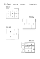
- FIG. 9A is an illustration of a tray stacking pattern for columns of trays to be inserted into all purpose containers
- FIG. 9B is an illustration of a brick-laid stacking pattern of columns of trays to be placed into all purpose containers or stack on pallets;
- FIG. 9C is an illustration of a more complete brick-laid pattern for transfer to pallets.
- FIG. 10 is a perspective view of a more complete system utilizing the second embodiment of the invention of FIG. 8;
- FIG. 11 is a block diagram of the controls architecture suitable for controlling the container loading systems of the present invention.
- FIG. 12 is a schematic diagram of the software architecture suitable for operating the controls system of FIG. 11;
- FIG. 13 is an illustration showing tray orientation and justification in the orientation modules of the present invention.
- FIGS. 14-17 are flowcharts illustrating the software process control for trays passing through container loading systems of the present invention.
- FIG. 18 is a perspective view of a preferred embodiment of a buffer wing assembly suitable for use in the systems of FIGS. 10, 19 and 20 of the present invention
- FIG. 19 is a diagrammatic illustration depicting a third embodiment of the present invention generally similar to the embodiment of FIG. 10, but utilizing conveyor belts for the transport conveyor, rather than the powered rollers of FIG. 10;
- FIG. 19A is a perspective view of two end-to-end sections of the belt conveyor of FIG. 19;
- FIG. 19B is a partial enlarged view of detail “A” of FIG. 19A depicting the support structure for the conveyor belts and relative location of the ejection rollers;
- FIG. 19C is a side elevational view of two sections of a transport conveyor according to FIG. 19A showing the transfer rollers in a down, retracted, position; on the right section and the transfer rollers up in the left section;
- FIG. 19D is an end elevational view of the conveyor sections of FIG. 19A depicting the ejection rollers at the near end section down, and the far end section up;
- FIG. 19E is a partial perspective view of the conveyor structure of FIG. 19A with the conveyor belts and ejection rollers removed to depict the actuation mechanisms for the ejection rollers;
- FIG. 19F is an enlarged perspective view of detail “A” of FIG. 19E depicting the mechanism for moving the ejection rollers up and down;
- FIG. 19G is an enlarged perspective view of detail “B” of FIG. 19E depicting the mechanism for imparting selective, bi-directional, rotation of the ejection rollers;
- FIG. 19H is a perspective view of one section of FIG. 19A with a top plate of one end removed to depict a position encoder mechanism
- FIG. 19I is an enlarged perspective view of detail “A” of FIG. 19H;
- FIG. 20 is a top-plan view showing two transport conveyors of the type utilized in the system of FIG. 19 with parallel longitudinal axes and facing, co-planar-buffer wings on opposite sides of a loading manipulator;
- FIG. 21 is an end elevational view of a container loading system of the present invention such as depicted in FIG. 19 showing the details of a loading manipulator and end effector assembly in a preferred embodiment of the present invention.
- FIG. 22 is a perspective view of a preferred embodiment of a safety curtain assembly of the present invention suitable for use with any of the system embodiments described herein.
- FIG. 1 illustrates the conveyor system of a first embodiment of the present invention comprising a plurality of modules placed in-line.
- the modules include transport conveyor sections 10 - 1 to 10 -N; in-line buffer sections 20 - 1 to 20 -N; and all purpose containers (APCs) 40 - 1 to 40 -N.
- a loading manipulator 30 including a platform 32 mounted for vertical movement on a post 34 is mounted on a track on the floor of the warehouse between the conveyors 10 ; in-line buffer sections 20 , and an associated one of the plurality of all purpose containers 40 .
- Loading manipulator 30 and its associated post 34 , move longitudinally of the modules 10 , 20 and the APCs 40 for alignment (one at a time) with a chosen module assembly under the control of a program in the central processing unit of the control system of the present invention and various readers or sensors.
- a plurality of mail trays 26 are shown in the perspective view of FIG. 1 at various positions before being transferred into the APCs 40 in a manner to be described more fully hereinafter with reference to FIG. 6 .
- Each of the conveyor sections 10 includes a base frame 12 , upstanding side rails 16 and a plurality of rollers 14 .
- the side rails include a plurality of spaced slide bars 18 for supporting the powered rollers 14 and permitting the movement of buffer finger conveyors 22 therebetween.
- FIG. 2 shows a single transport conveyor module 10 separated from the rest of the associated modules of FIG. 1 for clarity.
- FIGS. 3A and 3B illustrate the relative locations of the buffer finger conveyors 22 of buffer modules 20 between conveyor rollers 14 and spaced upstanding bars 18 of the side rails 16 .
- FIG. 3A shows this relative position in side elevation
- FIG. 3B shows this relative location in top plan.
- Buffer modules 20 include shelf assemblies 21 , each including four buffer finger conveyors 22 .
- each buffer finger 22 is a conveyor including a polycord belt 22 B fed around a plurality of pulleys 22 A.
- the outboard ends of each shelf assembly 20 are secured to a crossbar assembly 20 A which is slidably mounted on vertical bars 18 on side rails 16 .
- Vertical movement of crossbars 20 A is achieved by pneumatic cylinders (not shown).
- Each shelf assembly 20 reaches approximately half-way across the top surface defined by the conveyor rollers 14 .
- the shelf assemblies 21 in a normal or initial position are disposed below the top surface of rollers 14 in an interleaved manner illustrated in FIGS. 3A and 3B and once actuated extend to the upper positions illustrated in FIG.
- the buffer shelf assemblies 21 are individually actuated in response to control signals from the central computer in order to selectively form predetermined patterns of mail trays on the combined top surfaces thereof. Once shelves of the buffer assemblies reach the position illustrated in FIG. 4 they are fully covered by a pattern of mail trays and drive power may be applied thereto to the polycord belts rotating thereon clockwise to eject a full layer of mail trays at a time onto the platform assembly 32 of the loading manipulator 30 .
- the rollers 14 of the conveyor modules 10 are connected to appropriate drive motors which rotate rollers 14 in order to transport the mail trays along the top horizontal surface defined by the juxtaposed rollers.
- the rollers and/or the associated frame of each module 10 also include appropriate sensors for determining the presence of mail trays such as 24 , 26 thereon so that each tray as it moves along the conveyor system is tracked to determine its position in the system at any given time. This will be described more fully hereinafter with respect to the description of the system controls.
- FIG. 3 illustrates the loading manipulator 30 , as including a support post 34 longitudinally movable along a track 36 , a platform 32 movable vertically, up and down post 34 , on horizontal support arms 38 operatively connected for vertical movement on the post 34 .
- FIG. 3 illustrates loading manipulator platform 32 in an UP position in alignment with extended positions of a plurality of buffer shelf assemblies 21 and associated buffer finger conveyors 22 .
- a mail tray 24 is illustrated as bridging across a pair of buffer fingers 22 extending from respective, opposite side rails of the conveyor module. This mail tray 24 is a full length mail tray, whereas mail tray 26 is a half-tray, which can be supported by a buffer shelf 21 extending from only one side of the modular conveyor side rails 16 .
- FIG. 4 illustrates in more detail the appearance of the buffer shelf assemblies 21 and finger conveyors 22 of an in-line buffer 20 by depicting buffer finger conveyors in a fully extended UP position. These fingers would be in this position just after a full layer of mail trays 24 and/or 26 had been supported thereon, and were then transferred by loading manipulator 30 to the positions shown in the bottom of all purpose container 40 to insert a layer of trays therein. It should also be noted that the loading manipulator platform 32 has two telescoping platform sections 32 A and 32 B so that the top platform section 32 A can be extended into the open side of the all purpose container 40 .
- all purpose container 40 has three sides formed by vertical rails 40 A, 40 B, 40 C and the front side of the container is open for receipt of the mail trays.
- Containers 40 also have a bottom wall 40 D which supports the bottom of a stack of containers 24 , 26 loaded one layer at a time from the buffers assemblies 20 by the platform 32 .
- a middle shelf may be provided for stability and strength.
- FIG. 4 illustrates a single-sided right handed transfer configuration.
- FIG. 5 illustrates a double-sided alternative with APCs 40 disposed below a pair of conveyor 10 with rollers 14 .
- a single loading manipulator 30 with platform 32 serves the containers for both conveyors.
- the FIG. 5 embodiment provides a minimum footprint since containers 4 are disposed below the conveyors.
- FIG. 6 shows the general layout and flow of the system.
- the simplest example is loading sleeved and strapped trays into an APC 40 illustrated as 40 - 1 , 40 - 2 , 40 - 3 , 40 - 4 in FIG. 6
- Trays 24 are stacked in columns corresponding to the designations A, B, and C.
- Incoming trays 24 arrive from the facility on a conveyor system 42
- the trays 24 are scanned by a reader 44 , and are conveyed into the system through orientation module 50 , or are rejected if the bar code on the tray 24 is unreadable, or the tray per se is out of scheme with acceptable container criteria.
- Rejected trays are placed onto a gravity roller conveyor 46 for manual processing
- the orientation module 50 may include protruding pins to block progress of a corner or other portion of a tray 24 , causing the tray to rotate as the roller conveyor continues to run. This is one example of an orientation technique but other orientation devices of a robotic nature may be utilized in place of the protruding pins. However, for the purposes of illustration in FIG. 6 it should be assumed that the orientation module uses a plurality of pop-up pins that can be selectively fired to rotate the tray 24 right or left, or to pass the tray without rotation. In the example shown in FIG. 6 the pins will edge justify a moving tray 24 to either side of the belt conveyor for future alignment with a selected buffer shelf 21 .
- the type of pattern being constructed for the destination at a particular buffer assembly is determined; the tray 24 is conveyed to the appropriate buffer section and lifted from the conveyor.
- trays are stacked in columns corresponding to the designations A, B, and C.
- the first tray entering the system would be conveyed to a conveyor zone 1 - 2 shown in dotted lines. These two shelves 21 of conveyor zone 1 - 2 would lift the tray simultaneously into the buffer position in response to control signals from the central computer. Once this tray is raised to the buffer position, trays for other destinations can pass underneath it along the succession of conveyor modules 10 .
- Each buffer can selectively remove trays from the flow of trays on the conveyor without blocking that flow.
- the next tray When the next tray is received for this designation, it would be placed in zone 3 - 4 indicated in dotted lines, and the final tray in the layer would be placed into zone 5 - 6 .
- the container loader manipulator 30 removes the entire layer and places it into a container such as container 40 - 1 of FIG. 6 .
- buffer positions 7 - 8 can be used to group two half-trays 26 together.
- the first half-tray is conveyed to zone 8 , and lifted into the buffer position by an associated buffer shelf 21 .
- the next half-tray is conveyed to zone 7 .
- the half-tray in buffer position 8 is then lowered creating a pair of half-trays that can be conveyed into one of the downstream zones.
- a height sensor For taller (EMM) trays a height sensor identifies EMM trays in reader 44 . These trays can then be distributed among the stacked positions A, B, and C. For example on layer # 1 , positions A and B are EMM trays, and C is a standard tray (MM). On a layer # 2 to be placed in an appropriate container 40 , the first tray received is an EMM tray. It will be placed into position C to keep the stacked heights as even as possible.
- EMM standard tray
- the trays may be stacked as shown by pattern E, F, D wherein trays are oriented longitudinally of the conveyor in positions E and F and transversely of the conveyor in position D.
- This pattern is a modified brick-laying pattern which will now be described in more detail in connection with FIG. 7 .
- Open trays are preferably stacked in brick-laying patterns in either APCs or pallets in order to achieve a stable load that avoids some of the problems associated with nesting of partially filled trays.
- the brick-laying pattern is created with the orientation module 50 of the conveyor as described above. As an incoming tray is read by reader 44 , its destination and the pattern for loading into an appropriate container 40 , or a pallet associated with that destination, is determined.
- the brick-laid pattern for example may use the following buffer positions illustrated in dotted lines for odd and even layers:
- the brick-laid pattern is also preferably utilized to create stable stacks on pallets.
- the pallet bricklaid pattern is shown in FIG. 7 .
- the brick-laid pattern will be created such that each pallet layer has two sections (sections 1 and 2 in FIG. 7) these sections include for section 1 , four-tray sections and for section 2 , and a two-tray section as follows:
- Section 1 1 - 2 , 3 - 5 , 4 - 6 , 7 - 8
- Section 2 2 - 4 , 6 - 8
- Section 1 2 - 4 , 6 - 8
- Section 2 1 - 2 , 3 - 5 , 4 - 6 , 7 - 8
- the logic that was used for positioning half-trays using zones 9 and 10 of FIG. 7 and distributing the position of EMM trays in the APCs can also be used on palettes to achieve more efficient sorting and greater stability of the resulting package.
- the systems therein may also be provided with recirculation loops (not shown).
- the recirculation loop may consist of a return conveyor that runs over top of the buffer conveyor. If a buffer position is full, the recirculation loop will allow trays to pass by the destination buffer and recirculate to the input conveyor 42 rather than blocking the buffer conveyor until the buffer is empty.
- FIG. 8 illustrates a second embodiment of in-line buffer modules suitable for use in the automatic container loading system of the present invention (RCS)
- An input conveyor 42 transports incoming mail trays to a preliminary buffer station 80 .
- Buffer station 80 provides the capability of performing a preliminary sorting and buffering of half-trays (1 ⁇ 2 MM or SMM) according to a preselected criteria input into the central processing unit.
- the buffering unit 80 includes a first pair of buffer wing assemblies 82 L on the left side of the inbound conveyor 42 and a second pair of wing buffer assemblies 84 R on the right side of the inbound conveyor.
- Each of the buffer wing assemblies is provided with a plurality of unpowered letter rollers 83 so that a tray moved onto the top surfaces of these rollers will freely move in response to a lateral force applied thereto.
- a conveyor belt assembly 86 is disposed between the wing buffer assemblies for transferring mail trays selectively onto the wing buffer assemblies.
- This transfer conveyor belt assembly 86 includes five polycord belts disposed between the rollers of the inbound conveyor 42 . These polycord belts are provided with drive means (not shown) which rotate them about associated pulleys, in order to transfer trays to the right or left selectively in response to control signals.
- the belts of the transfer conveyor assembly 86 which are mounted on an elevator mechanism (not shown for clarity), raise the belts above the top surface of the rollers of conveyor 42 prior to applying the drive force which rotates the belts and laterally moves the trays to the destinations on the wing buffer assemblies 82 , 84 .
- orientation module 88 includes pairs of gripper arms illustrated in FIG. 10 to be described hereinafter.
- the orientation module of FIG. 8 includes a rectangular platform having a series of polycord conveyor belts 89 interleaved between powered transport rollers 87 . Trays arriving at orientation module 88 either exit, as is, or are turned to the proper orientations by gripper arms 53 which caress the trays and rotate them to proper orientations, in order to achieve selected patterns (such as brick-laid) downstream at an appropriate one of the respective in-line buffer assemblies.
- rollers 87 If a tray arriving from conveyor 42 onto rollers 87 is already oriented transversely of conveyor 10 , when it reaches the center point of rollers 87 , belts 89 will be raised above rollers 87 to lift the tray. Belts 89 will then be rotated to the left to transfer the tray to conveyor 10 on which it will proceed with its longitudinal axis at right angles to the axis of conveyor 10 . In this position it may be transferred longitudinally into a selected buffer storage wing. However, if a tray entering rollers 87 is to be oriented 90° from a normal tray position, such as when forming part of a brick-laid pattern, it will be carried by gripper arms 53 and rotated 90°. Belts 89 will then raise up and rotate to transfer the tray to conveyor 10 .
- the in-line buffer assemblies of this embodiment of the present invention are located downstream of the orientation module 88 .
- the buffer modules are designated 92 - 1 , 92 - 2 , and 92 - 3 .
- Each of these modules includes a pair of buffer wings similar to buffer wings 82 L and 84 R associated with the input conveyor 42 , but larger in order to accommodate various packaging patterns.
- the buffer wings of in-line buffer section 92 - 1 are designated 94 L- 1 and 94 R- 1 to represent the buffer wings on the left and right sides of the conveyor, respectively.
- the buffer wings of section 92 - 2 are designated 94 L- 2 and 94 R- 2 .
- the buffer wings of in-line buffer section 92 - 3 are designated 94 L- 3 and 94 R- 3 for the respective left and right wings.
- Each of the in-line buffer sections 92 - 1 , etc. are provided with a plurality of transfer conveyor belts 95 .
- these conveyor belts 95 are 13 in number.
- These conveyor belts are selectively elevated in groups by elevator mechanisms (not shown for clarity) in response to control signals from the central processing unit. Once elevated above the adjacent rollers of conveyor 10 , the belts are rotated either right or left in order to transfer trays to selected wings of the buffer assemblies. In this embodiment of the buffer assemblies trays are transferred one at a time into the respective side wings. Once the individual trays are transferred, they S are formed into groups of full layers on the respective wings include idler rollers 97 .
- the idler rollers 97 of the respective wing sections such as 94 L- 1 and 94 R- 1 may be divided into buffer zones 1 to 6 separated into three (3) channels such as illustrated in FIG. 9 . These zones provide the ability to achieve packaging patterns such as illustrated in FIG. 9A for packages with three (3) columns A, B, C, or a brick-laid pattern with columns E, F, D illustrated in FIG. 9 B. More specifically, to achieve the package configuration with columns A, B, C, of FIG.
- a tray for column A in a buffer wing such as 94 L- 1 would occupy zones 1 - 2 on the idler rollers 97 ; a tray for column B would occupy zones 3 - 4 ; and a tray for column C would occupy zones 5 - 6 .
- trays are rotated 90 degrees by the orientation module 88 in order to achieve the configuration illustrated in FIG. 9 B.
- a tray for column E would occupy zones 3 - 5 ; a tray for column F zones 6 - 4 ; and a tray for column D zones 1 - 2 .
- a more complete brick-laid pattern for pallets could be achieved as illustrated in FIG. 9C by providing eight buffer zones laterally across skate rollers 97 in the buffer wing assemblies.
- the pallet could be presented to the buffer wing with its longest dimension perpendicular to the wing.
- the delineation of zones such as 1 to 6 in FIG. 9, or 1 to 8 as could be used to achieve the full brick-laid pattern of FIG. 10, are controlled by the grouping the actuation of selected ones the 13 belt conveyors 95 in each of the in-line buffer modules. That is, the buffer conveyors 95 are actuated in selected groups according to control signals consistent with the package pattern criteria input into the central processing unit. Accordingly, the conveyor belts 95 may be grouped with respect to their actuation in correspondence to the zones required on the wing buffer assemblies to achieve the respective package layer criteria illustrated in FIGS. 9A to 9 C.
- FIG. 10 A more complete system utilizing the in-line buffer modules 92 of FIG. 8 is illustrated in the perspective view of FIG. 10 .
- buffer modules 92 - 1 to 92 -N are illustrated with mail trays moving along conveyor sections 10 .
- the formation of a complete layer of trays is illustrated on the wing buffer assembly 94 L- 3 .
- that wing buffer assembly is lowered by the depth of one layer in preparation for transfer of that layer of trays to an adjacent container 40 .
- the wing 94 is held stationary and the container or pallet is moved up and down to permit direct lateral transfer by the loading manipulator.
- a loading manipulator 96 mounted beneath the conveyor 10 and movable longitudinally thereof on a track (not shown).
- the loading manipulator includes a central post 100 and a shelf assembly 98 including telescoping top and bottom sections 98 A and 98 B.
- the operation of this loading manipulator is generally similar to loading manipulator 30 described hereinbefore with reference to the embodiment of FIGS. 1 to 7 . That is, it moves longitudinally up and down the conveyor line in response to control signals from the central processing unit to unload full layers of trays such as at buffer wing assembly 94 L- 3 into the opposed all purpose container 40 .
- top shelf of the shelf assembly 98 A extends to meet the buffer; and the layer of trays is edge-justified and pushed on the lower shelf of the manipulator end effector.
- the end effector lowers the layer to the correct insertion height and inserts them into an open end of the adjacent container 40 much like a spatula.
- the end effector is then pulled out from under the trays leaving them neatly stacked within the container 40 . Further details of the end effector are described in connection with FIG. 21 .
- FIG. 10 Also illustrated in FIG. 10 is a plurality of safety curtains 102 disposed around the containers 40 in order to protect factory workers from injury.
- a left bank of containers 40 on the other side of conveyor 10 is omitted for clarity.
- the loading manipulator 96 can transfer layers of trays assembled on the respective right and left wings of the buffer assemblies to containers 40 on both sides of the conveyor 10 since the loading manipulator 96 moves beneath the longitudinal access of conveyor 10 .
- FIG. 18 A preferred embodiment of a buffer-wing assembly 250 is illustrated in FIG. 18 .
- This assembly includes a top rectangular frame 258 having an open side for interfacing with the lower section of the loading manipulator.
- a tray storage section includes a plurality of idler rollers 252 journaled at their ends in a plurality of transverse supports.
- the top frame 258 is divided into the two respective sections by a transverse plate 253 , which functions as an indexing stop for the lower telescoping section of the end effector to be described more fully hereinafter with reference to FIG. 21 .
- the buffer wing section, including idler rollers 252 is provided with a stationary edge-justifying, alignment, plate 256 at one end and a movable compression plate 254 at an opposite end.
- Plate 254 is movable across the longitudinal dimension of roller 252 toward stationary plate 256 by a pneumatic actuator (not shown) disposed beneath rollers 252 .
- the top frame 258 is supported by a scissors assembly 260 , including scissor arms 260 A, 260 B and 260 C, 260 D connected to the respective side channels of frame 268 .
- a bottom frame 262 with side channels 263 supports the bottom of the scissor arms.
- Scissor arms 260 B and 260 D are fixedly secured in the corners at one end of frame 262 at 261 .
- scissor arms 260 A, 260 C have rollers 260 W on the bottom thereof, which roll in the L-shaped side channels 263 as the buffer wing assembly is raised and lowered.
- the scissors assembly is raised and lowered by pneumatic actuator 264 , which includes a cylinder 266 and reciprocating actuator shaft 268 coupled to a cross-bar 265 connecting the scissors' arms at the cross-connecting pivot points thereof.
- the buffer wing assembly functions as a staging platform that accepts the trays from the transport conveyor, forms a layer, and presents the layer to the loading manipulator 300 , to be described in more detail hereinafter.
- the cell control computer sort plan determines the proper tray location within a layer, and instructs the transport conveyor to eject the appropriate tray in the proper position (to satisfy either column or brick layer patterns) onto a designated buffer wing, such as illustrated in FIG. 18 .
- a pneumatically activated compression mechanism pushes the trays sideways along the buffer width moving compression plate 254 towards stationary edge justifying plate 256 .
- the buffer wing then rapidly lowers by contraction of the actuator rod 268 in cylinder 266 to pivot the scissor arms, which move the frame 258 to the correct height for transfer of the layer of trays to the loading manipulator 300 .
- the buffer wing assembly 250 raises back to the level of the transport conveyor to receive new trays.
- the manipulator 300 is located beneath the transport conveyors, such as TCI and TCII, which may be for the sake of explanation, the pair of parallel transport conveyors provided in a fourth embodiment of the invention depicted in FIG. 20 .
- the manipulator 300 moves longitudinally on a track in a manipulator aisle disposed between the respective transport conveyors.
- the manipulator 300 utilizes a telescoping end effector mounted on a raise/lower axis to interface with each buffer wing 250 , in order to retrieve single layers of trays and load them into containers on either side of the manipulator aisle.
- the end effector consists of a bottom extensible shelf 304 , and a separately operated top extensible shelf 302 with a rotating sweep gate 306 mounted thereon.
- the bottom shelf 304 of the end effector extends to meet the buffer wing and indexes on transverse plate 256 , while the top portion 302 of the end effector reaches over the top layer of trays on rollers 252 , deploys sweep gate 306 , and sweeps/rakes the layer of trays onto the bottom telescopic section 304 , which provides a shelf for supporting the trays.
- Both the top and bottom portions of the extensible end effector retract, end effector is then lowered into the correct position for inserting the trays into an appropriate container or pallet 40 .
- the bottom shelf 304 of the end effector with the layer of trays thereon extends the proper distance into the container or over the pallet. That is, as illustrated in FIG. 21 the telescopic section 304 A of the bottom section extends outwardly from telescopic section 304 B into the container C, or into the region above a pallet P, for unloading of the trays onto those devices.
- the top portion 302 of the end effector is extended by telescoping its respective sections 302 A and 302 B, and the sweep gate 306 is deployed up against the layer of trays so that the layer cannot be retracted from the container or pallet.
- the extensible bottom shelf 304 A is then retracted thereby depositing the layer of trays in the container or on the pallet.
- the sweep gate 306 is then rotated out of contact with the trays leaving the layer of trays in position as the top end effector 302 is retracted.
- the safety curtain assembly 102 includes a movable, steel slat curtain 102 C that surrounds each individual loading station on three sides forming a “U”. This “U” is defined within a rectangular frame assembly 102 F having a track 102 T extending around the perimeter thereof at the top of the frame.
- the safety curtain 102 C includes a plurality of hinged vertical slats having slider assemblies, such as rollers, hooks or the like, on the top ends thereof mounted for slidable movement within the track 102 T.
- the open side of the “U” is facing the manipulator 300 providing access for loading layers of trays into the container and prohibiting manual entry into the loading cell. See for example, the closed condition of all but one of the cells illustrated in the system of FIG. 19 .
- the curtain 102 C is reoriented to where the open side of the “U” faces away from the manipulator 300 . See for example, the single open cell illustrated in the FIG. 19 system. In this orientation, the safety curtain 102 C blocks manipulator access to the loading cell, and allows, safe, manual access by a postal worker to remove the container/pallet.
- This “U” arrangement on each loading station offers the benefit of uninterrupted robotic loading operations while removing/replacing full containers manually.
- the safety curtain design mutually excludes interaction between the postal operator and the manipulator 300 at all times.
- Slats 102 C may be split into two sections at split gate SG.
- Magnetic locks ML connect the two sections at SG.
- Magnetic locks also connect like rear ends of curtain 102 C to frame 102 F.
- a gate button GB may be provided to release the magnetic locks.
- FIG. 19 which utilizes conveyor belts for the transport conveyor rather than power rollers as in the FIG. 10 embodiment, there is illustrated a transport conveyor TC with a plurality of parallel transport conveyor belts TCB extending along the longitudinal axis of the transport conveyor.
- Mail trays are conveyed on inbound conveyor 42 into an orientation module 88 , such as described hereinbefore with reference to the system of FIG. 10 .
- the orientation module 88 rotates the trays in the proper direction, if necessary, in order to achieve column or brick-laid patterns.
- the trays are discharged from the orientation module 88 for appropriate orientation for loading into a container.
- the trays are fed from the orientation module 88 onto the transport conveyor TC through an induction module IM, including a series of sensors A, which fix the point in time at which each tray enters the transport conveyor and sends appropriate signals to the cell control computer.
- IM induction module
- the transport conveyor moves the trays, feeds and sorts them according to the destination codes thereon onto a series of buffer wings 92 , 94 disposed on the respective sides of the transport conveyor
- the buffer wings 92 , 94 temporarily store the trays until a complete layer is assembled therein for subsequent transfer to appropriate containers or pallets.
- the cell control computer tracks the progression of the trays through the use of a shaft encoder SE operatively connected to the drive mechanism of the conveyor belts, as illustrated in FIGS. 20H and 20I to be described hereinafter.
- Individual trays are ejected at right angles to the transport conveyor onto the desired buffer wings 92 , 94 in proper orientations and positions.
- the wing lowers and compresses the trays for transfer to a manipulator 300 in a manner described hereinbefore with reference to FIG. 18 .
- the manipulator 300 with the extensible end effector 302 , 304 described hereinbefore with reference to FIG. 21, retrieves the layer of trays from the lower buffer wing.
- the buffer wing then elevates back into normal position in the plane of the transport conveyor in order to accept additional trays.
- the manipulator 300 then lowers and deposits the layer of trays into the corresponding container or pallet.
- the transport conveyor is a multi-belt conveyor design for transporting trays and utilizes a series of pop-up ejection rollers PR mounted at the location of each pair of buffer wings to eject the trays at right angles to the main transport axis of the conveyor TC onto the wings.
- the multi-belt conveyor consists of a series of small belt strips TCB spaced apart such that the powered rollers PR are nested between each belt and are normally below the conveying surface of the belts to allow the trays above to pass.
- the powered rollers PR are air actuated to an elevated position (higher than the surface of the belts) and an electric motor EM powering the rollers is driven either clockwise or counterclockwise to transfer the mail tray to the left or right buffer wing 92 , 94 at the appropriate time.
- the powered rollers are then retracted to the down position to allow additional trays to pass above.
- the respective up and down positions of the powered rollers with respect to the belts TCB is depicted in FIGS. 19A and 19B.
- FIGS. 19A-19E illustrate, in detail, the mechanism for activating ejection rollers PR to selectively transfer trays to the buffer wings.
- FIG. 19A depicts two conveyor sections TC 1 ; TC 2 disposed end-to-end with the plurality of spaced, parallel, conveyor belts TCB.
- FIG. 19B is an enlarged view of detail “A” of FIG. 19A illustrating the two conveyor sections with the belts TCB removed in order to illustrate parallel belt guides BG, which are disposed below each belt to guide the same longitudinally of the conveyor sections as they move therealong. Also, illustrated more clearly in FIG. 19B are ejection rollers PR disposed between each of the belt guides BG.
- FIG. 19C is a side elevational view of the conveyor section TC 1 , TC 2 of FIG. 19A illustrating the rollers PR in section TC 1 in an up position where they extend slightly above the level of the belt guides BG, and the rollers PR in the down position in section TC 2 where they are obscured from view by the belt guides BG.
- Another illustration of the up and down position of the respective rollers PR is illustrated in the end elevational view of FIG. 19 D.
- FIGS. 19E-19G illustrate in more detail the actuating mechanisms of the rollers PR, which enable the rollers to eject trays from the conveyor belts TCB onto selected buffer wings disposed to the right or the left of the transport conveyor.
- an air cylinder AC is provided transversely of the conveyor section at one end thereof and includes a pair of actuator rods AC 1 and AC 2 extending from the respective ends of the cylinder AC for reciprocating movement.
- the distal ends of the rods AC 1 , AC 2 are in turn coupled to a chain CH, which winds around pulleys P 1 , P 2 in an endless fashion.
- a cam plate CP is mounted to the rear of air cylinder AC and is movable transversely of the conveyor section in response to movement of the actuator rods AC 1 , AC 2 and chain CH about pulleys P 1 , O 2 .
- cam plate CP is provided with a series of notches or depressions in which the rollers PR (not shown) are normally disposed when in a down position and a plurality of peaks or cam protrusions, which engage the bottom of rollers PR and lift them above the position of the belts TCB depending upon the position of air cylinder AC transversely of the conveyer. That is, actuation of air cylinder AC causes cam plate CP to shift left or right to raise or lower the ejection rollers PR above or below the conveyor belts TCB.
- FIG. 19G illustrates the mechanism for rotating the ejection rollers PR either left or right to eject trays to left or right buffer wings respectively.
- an electric motor EM is provided in a slot in a cam plate CP and has a drive shaft thereof coupled to an endless belt EB wound around spaced pulleys P 3 , P 4 .
- the belt B has raised portions B 1 , which frictionally engage the bottom of the rollers PR and rotate the rollers left or right depending on the direction of rotation of the electric motor EM. Accordingly, a tray resting on a set of elevated rollers PR can be selectively transferred left or right into an appropriate buffer wing by the motor EM and the associated belt B by the protrusions Bi, which engage the bottom of the rollers PR.
- conveyor belts TCB transport the tray by maintaining a continuous friction contact surface with the bottom of the tray. This eliminates the probability of tray rotation caused by the sliding friction between the tray and powered rollers and the transfer of the trays between roller-conveyor zones. Since belts provide a constant contact with the tray, the potential for tray rotation is greatly minimized thereby enhancing the ability to maintain tray orientation over long distances.
- a belt conveyor allows the use of a single position sensor; shaft encoder SE, in lieu of multiple optical sensors to be used for tracking the progression of trays.
- shaft encoder SE associated with the drive mechanism of the belts is utilized to provide highly accurate position information for each tray moving along a conveyor section. This shaft encoder SE is zeroed by signals from the induction module IM with respect to each tray entering the system, as described above, so that the cell control computer knows where each tray is, and can activate the powerful ejector rollers to move a tray to the proper buffer wing.
- FIGS. 19H and 19I Further details of the shaft encoder SE of the present invention are illustrated in FIGS. 19H and 19I.
- the shaft encoder SE is mounted on a bracket EB, which in turn is mounted on a transverse encoder slide rod SR.
- Encoder SE which is depicted as a round disk, is positioned for frictionally engagement with encoder roller ER extending transversely of the conveyor mechanism and journaled in the side walls of the frame structure thereof.
- Encoder roller ER is rotated by the conveyor belts TCB (not shown for clarity), which are fed underneath the same, up around and over, the idler belt pulley BP disposed in slots in the side walls of the end structure of the conveyor assembly.
- a fourth embodiment of the present invention is shown in the system layout of FIG. 20 .
- This system includes first and second parallel conveyors TCI and TCII. These conveyors are disposed on opposite sides of a center aisle and straddle that aisle with facing buffer wing assemblies BWI, BWII on the inside of each conveyor.
- Two loading manipulators 300 I, 300 II are mounted on tracks for movement over approximately one-half of the length of the respective layers for cooperation with the facing buffer wing assemblies in a manner described herein before.
- the buffer wing assemblies need not be supported on elevator structures, but may remain coplanar with the respective transport conveyors TCI, TCII.
- the buffer wings move up and down into operative alignment with loading manipulators 300 disposed below the level of the transport conveyors
- the loading manipulators still are moveable vertically in order to transfer one layer at a time of trays from the buffer wings into the appropriate mailing containers or pallets.
- Each loading manipulator 300 I, 300 II also has an associated service position SPI, SPII at the distal ends of the tracks on which they are mounted. When in the service positions, good access is available to the loading manipulators to correct whatever problem might arise. This also enables one-half of the loading manipulator assembly to operate independently of the other half so that the system need not be shut down during service and repair of one of the respective loading manipulators.
- Trays moving through the system of FIG. 20 enter the system on infeed conveyor 42 and pass through the first merge point M 1 , which intersects with the recirculation conveyor RCI or RCII from the outputs of the respective conveyors TCI, TCII.
- the trays are then conveyed through an identification module ID wherein the barcodes thereon are read by the reader and input into the cell control computer.
- Trays then pass on through a series of buffer modules 80 described herein before with respect to other embodiments, which accumulate half-trays until they can be combined downstream with other half-trays in appropriate ones of the buffer wings.
- Trays exiting buffer modules 80 pass on to a first diverter D 1 , which is connected to a reject conveyor RJ so that unacceptable, non-conforming trays may be rejected and removed from the system.
- the trays then pass on to a diverter D 2 , which divides the trays into one group directed towards transport conveyor TCI on an infeed conveyor 421 ; and a second conveyor TCII via an infeed conveyer 42 II.
- the input to each of the conveyors includes orientation modules 88 I, or 88 II for orienting the trays into proper positions before they enter their respective transport conveyors TCI, TCII.
- Each transport conveyor also includes an induction module IM-I, IM-II, which comprises a plurality of parallel sensors which detect the presence of a tray input to the conveyor and generate initiation signals to the shaft encoders described herein before and the computer cell controller, which tracks the position of the trays along the transport conveyors and transfers the trays to appropriate buffer wings in the manner described with respect to other embodiments of the present invention.
- IM-I induction module
- IM-III which comprises a plurality of parallel sensors which detect the presence of a tray input to the conveyor and generate initiation signals to the shaft encoders described herein before
- the computer cell controller which tracks the position of the trays along the transport conveyors and transfers the trays to appropriate buffer wings in the manner described with respect to other embodiments of the present invention.
- the loading manipulators 300 I, 300 II move along the support tracks into alignment with that buffer wing and transfer the entire layer of trays onto the loading manipulator using the end defector assembly of FIG. 21 into the appropriate container or pallet. Trays passing along the transport conveyors TCI, TCII, which are not transferred to a container at this time, will emerge from the outputs ends of the transport conveyors on to the respective recirculation conveyors RCI, RCII and are fed back through the system until they are either rejected or transferred to one of the respective buffer wings.
- FIG. 20 Other features of the system of FIG. 20 such as catwalks CWI, CWII are illustrated. However, some of features of the system such as the containers per se' and the safety curtain assemblies, therefore, are not illustrated in FIG. 20 for clarity.
- control blocks namely main line control block 44 C; infeed control block 80 C; orientation module control block 88 C; and buffer conveyor control block 92 C. Electrical power is supplied to each of these control blocks through BUS 113 and air supply is provided through air distribution BUS 115 .
- the MAIN LINE control block 44 C performs the function of reading the barcodes on the mail trays and controlling the conveyor diverters.
- Infeed control block 80 C controls the operation of the infeed buffer zone 80 , and the transfer conveyor controls thereof. It also obtains product parameters for the trays stored in the infeed buffer zone.
- the orientation module 88 C controls the orientation of the trays at the orientation module 88 according to the packaging criteria.
- the buffer conveyor control block 92 C controls the operation of the conveyor sections at each buffer module and the transfer operation of the conveyor belts 95 interposed between the conveyor rollers.
- FIG. 11 also illustrates another group of control blocks 114 , 116 , 118 and 120 .
- Control block 114 provides for cell-type detection, namely presence detection of trays, tray type detection, tray height measurement, and shelf detection.
- Buffer conveyor reject control block 116 controls the recirculation loop of mail trays if a buffer module position to which the tray is directed is full.
- Infeed reject control block 118 controls the rejection of non-conforming trays and trays that are not within the sort plan.
- Control block 120 controls the operation of container pallet loading including container lifting, layer pushing, layer compression, layer movement and layer placement.
- the details of operation of the hardware of FIG. 11 is implemented by software architecture to be described hereinafter with reference to FIG. 12 .
- the software is partitioned into specific functional components.
- the software consists of machine control software, the Human Machines Interface (HMI) software and system configuration software.
- the machine control software is responsible for all the machine operations. This includes the conveyor operation, SRM operation, in-line buffer operation, and fault detection.
- the HMI software allows the users to view the status of the system, view faults, and perform various data collection that is needed.
- the system configuration software allows the user to configure the Robotic Containerization System (RCS) as needed. The user has the ability to configure the system as left or right handed, as well as dual sided.
- the number of containers and/or pallets is also configurable.
- FIG. 12 depicts the high level functional data flow between the sections of software. The following is a description of the software operation of the various components of the system.
- Buffer Conveyor Machine Control 130 When a tray enters the work cell, it will arrive on the infeed conveyor 42 associated with a barcode Buffer Conveyor Machine Control 130 will control the operation of the infeed conveyor, as well as track the tray along this conveyor. Any jam recovery will be handled by Buffer Conveyor Machine Control. Along the infeed conveyor, certain information must be obtained, that will be used to determine container orientation, justification and whether the tray should be rejected. RCS Cell Control 134 will be responsible for determining the container assignment, the orientation, justification, and tray rejects Once a container is determined, Buffer Conveyor Machine Control will know to which conveyor line and orientation/justification module the tray is destined. A diverter will send the tray to the correct conveyor line (assuming that there is more than one). This will be controlled by Buffer Conveyor Machine Control 130 . RCS Cell Control 134 will determine the orientation and justification of the tray. This information will be used by key Handling to control the operation of the Orientation such as 88 .
- the orientation/justification module 88 is controlled by Buffer Conveyor Machine Control 150 .
- Buffer Conveyor Machine Control will be given the orientation and justification for the tray.
- the tray will be oriented and aligned and sent down the conveyor to the correct in-line buffer position.
- the buffer position is determined before this module is entered.
- the tray is sent to the correct in-line buffer Buffer Conveyor Machine Control will track the tray to the correct in-line buffer module, and recover from any jams which may occur.
- In-line buffer modules 92 are controlled by Buffer Conveyor Machine Control 130 . Once a tray reaches the correct buffer module, it is put into the correct position Once a tray is successfully put into the in-line buffer module, this status is indicated to RCS Cell Control 134 .
- RCS Cell Control 134 keeps track of each layer, and when a layer is complete, determines which in-line buffer module will be accessed by the manipulator. RCS Cell Control 134 notifies the SRM 136 that it needs to move to the correct in-line buffer module. Once it is determined that the SRM 136 is at the correct location, RCS Cell Control 134 will indicate to Buffer Conveyor Machine Control 130 and the loading manipulator 136 to begin transfer. Buffer Conveyor Machine Control 130 will notify RCS Cell Control 134 of a successful transfer. Once a successful transfer has been confirmed from both Buffer Conveyor Machine Control 130 and the loading manipulator (SRM) 136 , RCS Cell Control 134 will signal the manipulator (SRM) 136 to transfer the layer into the container.
- SRM manipulator
- This section describes the operating scenario of the RCS system of the present invention. It outlines the flow of mail trays into the RCS as well as detailed operations within the work cell.
- the system controls includes the computer hardware of FIG. 11 and software of FIG. 12 required to operate the RCS. This includes the interface to an existing United States Postal System (USPS) “starship” system, sort plan generation, reports and on-line data, and sort monitoring.
- USPS United States Postal System
- the RCS system must interface to existing USPS systems to obtain data such as default processing schedules and also allows for the remote access to cell activity reports, cell failure/trouble logs.
- the sort plan generation is a function performed by In-Plant Support personnel within the Robotic Containerization System (RCS) system of the present invention.
- RCS Robotic Containerization System
- a default sort plan is downloaded and stored within the RCS computer 110 .
- the sort plan may be changed in real time by authorized personnel.
- Raw report information is stored within a SQL database on the RCS computer 110 . This information may be shared with other USPS systems using an ORACLE database.
- the RCS system allows USPS personnel to generate reports. Below is a list of the USPS personnel and the types of reports that will be generated
- Plant Management Summary and Detail Volume reports, Availability reports, Performance reports.
- the RCS system includes a Human Machine Interface (HMI) 112 , 132 , which includes a graphical depiction of the system operation as well as system status. Other information such as tray barcodes, container details, robot status are also available via the User Interface.
- HMI Human Machine Interface
- the HMI also provides an on-line Maintenance mode to check various functions of the system.
- the operator will be able to control conveyor operation, in-line buffer operation and orientation/justification operation from the user screen.
- the RCS interfaces to a Tray Management System (TMS) or other existing conveyor. Trays and tubs are diverted into the work cell based upon a barcode. The barcode is read, and any tray or tub contained in the sort plan is passed into the RCS.
- TMS Tray Management System
- the tray Once inducted into the system, the tray enters an infeed conveyor 42 . At this point, the tray is checked for a DNR tag by reader 44 . The tray or tub is checked to determine height, width and length. The barcode and/or DNR tag, as well as height and length, are used to determine the tray/tub container destination.
- FIG. 9 depicts the buffer positions on the In-line Buffer Module. Operation, of the In-line Buffer Module is detailed in all embodiments described hereinbefore.
- Each in-line buffer has up to 10 buffer positions in the various embodiments, which are used to store half trays and trays waiting to be transferred to the container or pallet.
- the buffer positions are used in different combinations to achieve the “brick laying” or column stacking effect depicted in FIGS. 6, 7 , 9 , 9 A, 9 B, and 9 C.
- An Orientation/Justification Module 88 is used to orient and justify trays entering the system. In a right or left handed system, there will only be one Orientation/Justification Module 88 . In a dual sided system, there will be two Orientation/Justification Modules 88 . In a single sided system, the Orientation/Justification Module 88 will pass the rejected trays to the reject conveyor, and orient and justify the trays to the correct position. In a dual sided system, the first Orientation/Justification Module 88 will orient and justify the trays that have destinations on the conveyor which it services.
- the first Orientation/Justification Module 88 will pass the tray to the second Orientation/Justification Module 88 where it will either pass the tray to the reject conveyor or orient and justify the tray.
- the Orientation/Justification Modules' 88 purpose is to rotate the product into the correct orientation for it to be inserted into the container It also positions the product at the proper location on the powered roller conveyor in order to fit into the In-line Buffer Module.
- the orientation and justification can be thought of as rotating and sliding pieces of a puzzle together to form the correct fit.
- FIG. 13 shows the process of orientation and justification In the RCS, the location is determined by the pattern being built on an In-line Buffer Module for loading into a particular container/pallet.
- Orientation/Justification Module 88 In order to accomplish the three objectives required to the Orientation/Justification Module 88 , passing a tray, orientating a tray and justifying a tray, information must be exchanged between these modules and the rest of the controls. Any conditions causing rejection of a particular tray need to be input to the Orientation/Justification Module 88 . These include tray too long, tray too wide, tray too tall, no read, and out of sort plan. The Orientation/Justification Module 88 only needs to know whether a tray is to be processed or rejected. The application software will then be responsible to provide for unique handling conditions dependent on the reject type and to provide the flexibility of sort-plan dependent rejection. For example, in one sort-plan no-read trays could be rejected while in a different sort-plan no-read trays could sort to a particular container.
- the second Orientation/Justification Module 88 would not require the first two conditions.
- the Orientation/Justification Module would not have to return to a “home” position before receiving the next tray. In order to properly justify the tray to the correct edge of the conveyor, the Orientation/Justification Module 88 would need to receive only one of two states; inside of conveyor or outside of conveyor. If the tray length is oriented across the width of the conveyor in the In-line Buffer Module then the tray positioning can only be in the center of the conveyor.
- the In-line Buffer Module is used to store trays/tubs until ready for transfer into the container or pallet. Three embodiments of In-Line Buffer Modules have been described hereinbefore.
- FIGS. 14 to 17 The process flow of a mail tray passing through the system of the present invention is illustrated in FIGS. 14 to 17 .
- a new tray enters the system at step 200 and passes past a barcode reader, which asks the question in decision block 201 “Is tray barcode in sort plan?” If the answer is NO, the tray returns to the main stream through loop 202 . If the answer is YES, the tray continues into the robotic containerized loading system as indicated by block 203 . The tray then passes through another reader mechanism as illustrated in step 204 and the reader determines if the tray width, length, and height are within acceptable limits If the answer is NO, the tray returns to the mainstream path 202 . If the answer is YES, the tray type is then determined in step 205 . In step 216 it is asked whether the tray is a flat tub. If YES, the program proceeds to subroutine (A). If NO, the software program proceeds to step 207 . In step 207 it is asked whether the tray is GMEMM or MM tray. If YES, the software proceeds to subroutine (A). If NO, the software proceeds to subroutine (B).
- subroutine (A) of the flowchart Beginning at step 208 , it is determined for which container(s) is the tray destined. In step 209 it is asked if the container is full? If YES, the tray returns to mainstream 202 . If NO, the software proceeds to step 210 , which asks if the layer is complete? If YES, the tray returns to mainstream 202 , if NO, the software proceeds to step 211 to determine the position and orientation desired for the tray. The position and orientation so determined is sent to the orientation module at step 212 , and once oriented the tray convey control signal is initiated at step 213 . At step 214 the command is given to place the tray into the proper buffer location. At step 215 it is asked whether the layer is complete if NO, the software routine returns to 200 with a new tray. If YES, a command is generated to indicate that the layer is ready to be loaded into the container. The program then proceeds to subroutine (C).
- step 217 is a command to load the layer into the container.
- Step 218 is a command to indicate that the layer has been loaded into the container. That is, a signal associated with the load manipulator will advise the central processor that the layer has been loaded.
- the software then proceeds to the END at step 219 .
- step 21 identifies containers that are to receive SMM (1 ⁇ 2 MM) trays.
- Step 21 asks is the container to which it is assigned full? If YES, the container returns to mainstream 202 . If NO, the software proceeds to step 222 and asks the layer is complete? If YES, the container returns to mainstream 202 , if NO, the software proceeds to step 223 , which asks if there is an SMM tray buffer? If NO, the software proceeds to step 224 and asks if there is an available buffer space, If NO, the tray returns to 202 , the mainstream.
- step 225 the software proceeds to step 225 and asks the question if an available buffer storage zone for an SMM tray is available, and if so, where is it located? The software then asks for a new tray at 202 to be fed into the system. If the answer to step 223 is YES, step 226 then determines the position and orientation of the tray being processed.
- step 227 a command is initiated to put the buffered tray onto the conveyor.
- step 228 the command is to send the first SMM tray to the orientation module 88 .
- step 229 the software commands the system to send the second SMM tray to the orientation module 88 .
- step 230 the software commands the system to convey both SMM trays to the appropriate container.
- step 231 the software commands the system to place SMM trays into appropriate buffer locations.
- the software then proceeds to subroutine (D).
Abstract
Description
Claims (62)
Priority Applications (1)
| Application Number | Priority Date | Filing Date | Title |
|---|---|---|---|
| US09/310,222 US6201203B1 (en) | 1999-05-12 | 1999-05-12 | Robotic containerization system |
Applications Claiming Priority (1)
| Application Number | Priority Date | Filing Date | Title |
|---|---|---|---|
| US09/310,222 US6201203B1 (en) | 1999-05-12 | 1999-05-12 | Robotic containerization system |
Publications (1)
| Publication Number | Publication Date |
|---|---|
| US6201203B1 true US6201203B1 (en) | 2001-03-13 |
Family
ID=23201503
Family Applications (1)
| Application Number | Title | Priority Date | Filing Date |
|---|---|---|---|
| US09/310,222 Expired - Lifetime US6201203B1 (en) | 1999-05-12 | 1999-05-12 | Robotic containerization system |
Country Status (1)
| Country | Link |
|---|---|
| US (1) | US6201203B1 (en) |
Cited By (45)
| Publication number | Priority date | Publication date | Assignee | Title |
|---|---|---|---|---|
| US6353774B1 (en) * | 2000-09-22 | 2002-03-05 | Virtek Engineering Sciences Inc. | High precision vision guided positioning device |
| WO2002058308A2 (en) * | 2001-01-16 | 2002-07-25 | Abb Automation, Inc. | Dynamic sortation of items in a containerization system |
| US6503043B1 (en) * | 2000-10-17 | 2003-01-07 | Lebleu Corporation | Multiple level loading apparatus and method |
| EP1315582A2 (en) * | 2000-06-26 | 2003-06-04 | United States Postal Service | Method and system for single pass letter and flat processing |
| US6610954B2 (en) * | 2001-02-26 | 2003-08-26 | At&C Co., Ltd. | System for sorting commercial articles and method therefor |
| US20030176944A1 (en) * | 2002-03-13 | 2003-09-18 | Stingel Frederick J. | Automated container storage and delivery system |
| US20030235491A1 (en) * | 2002-04-22 | 2003-12-25 | Subotincic Milos Misha | End effector with multiple pick-up members |
| EP1393823A2 (en) * | 2002-06-18 | 2004-03-03 | Böwe Bell & Howell Company | Progressive modularity assortment system with high and low capacity bins |
| US20040074977A1 (en) * | 2001-02-21 | 2004-04-22 | Rainey Brent A | Tracking label |
| US20040074561A1 (en) * | 2001-03-24 | 2004-04-22 | Manfred Boller | Method for franking and processing deliveries |
| US20040074823A1 (en) * | 2002-10-17 | 2004-04-22 | Vertique, Inc. | Determining pallet case configurations for placement by a robot |
| US20040074965A1 (en) * | 2001-02-21 | 2004-04-22 | Raney Brent A. | Systems and methods for utilizing a tracking label in an item delivery system |
| US20050002772A1 (en) * | 2003-07-03 | 2005-01-06 | Stone Robert L. | Mail container handling system |
| US20050058531A1 (en) * | 2003-09-12 | 2005-03-17 | Wisniewski Michael A. | Storage device |
| US20050075997A1 (en) * | 2001-02-21 | 2005-04-07 | Rainey Brent A | Systems and methods for producing and managing a tracking label in a an item delivery system |
| US20050224399A1 (en) * | 2003-09-17 | 2005-10-13 | Guy Forella | Bin tranferring structure for a postal sorting machine |
| US20060219610A1 (en) * | 2005-03-17 | 2006-10-05 | Lockheed Martin Corporation | Tray stacking and buffer system and method of use |
| US20070005181A1 (en) * | 2002-03-13 | 2007-01-04 | Stingel Frederick J Iii | Automated container storage and delivery system |
| US20070201968A1 (en) * | 2006-02-24 | 2007-08-30 | Northrop Grumman Systems Corporation | Automated flats divider |
| WO2008080558A1 (en) * | 2006-12-29 | 2008-07-10 | Sigmund Kumeth | Transport system for workpieces |
| US20090223878A1 (en) * | 2004-12-10 | 2009-09-10 | Scanvaegt International A/S | Method and a system for batching of objects |
| US20090257858A1 (en) * | 2007-10-10 | 2009-10-15 | Andre Weclawski | Device with multiple engagement members |
| US20100200370A1 (en) * | 2009-02-12 | 2010-08-12 | Krones Ag | Conveyor system and method for feeding to a downstream processing unit |
| US20110211939A1 (en) * | 2008-12-23 | 2011-09-01 | Solystic | Postal sorting machine with a carriage for handling mailpieces |
| DE10358794B4 (en) * | 2003-12-12 | 2012-10-04 | Eurocopter Deutschland Gmbh | Near-field measurement method for printed circuit boards |
| US20130268111A1 (en) * | 2011-10-10 | 2013-10-10 | Jonathan P. Dekar | Method and apparatus for monitoring food type and position |
| US20140156060A1 (en) * | 2012-11-30 | 2014-06-05 | Stork Fabricators, Inc. | Automatic container orientation systems and methods |
| US8857709B2 (en) * | 2012-07-31 | 2014-10-14 | Flextronics Ap, Llc | Automatic package delivery and retrieval system |
| GB2524383A (en) * | 2014-02-10 | 2015-09-23 | Ocado Innovation Ltd | Intermediate holding facility for picking station |
| US20160257240A1 (en) * | 2015-03-06 | 2016-09-08 | Wal-Mart Stores, Inc. | Method and apparatus for transporting a plurality of stacked motorized transport units |
| DE102015218655A1 (en) | 2015-09-28 | 2017-03-30 | Siemens Aktiengesellschaft | Mail sorter |
| GB2544648A (en) * | 2015-11-11 | 2017-05-24 | Ocado Innovation Ltd | Storage containers, bins and devices |
| US9796540B1 (en) | 2010-06-30 | 2017-10-24 | Thiele Technologies | System and method for robotic palletization of packages susceptible to package-to-package dimensional creep |
| US10017322B2 (en) | 2016-04-01 | 2018-07-10 | Wal-Mart Stores, Inc. | Systems and methods for moving pallets via unmanned motorized unit-guided forklifts |
| CN108906636A (en) * | 2017-12-28 | 2018-11-30 | 南京涵曦月自动化科技有限公司 | A kind of automatic intelligent sorting equipment for logistics transportation |
| US10346794B2 (en) | 2015-03-06 | 2019-07-09 | Walmart Apollo, Llc | Item monitoring system and method |
| US11046562B2 (en) | 2015-03-06 | 2021-06-29 | Walmart Apollo, Llc | Shopping facility assistance systems, devices and methods |
| US11103896B2 (en) * | 2019-07-08 | 2021-08-31 | Siemens Logistics Llc | Parcel sorting system and method |
| EP3929111A1 (en) * | 2020-06-24 | 2021-12-29 | Tata Consultancy Services Limited | Apparatus and method for packing heterogeneous objects |
| CN114260188A (en) * | 2021-12-30 | 2022-04-01 | 宁波智能制造技术研究院有限公司 | Multi-station multi-equipment intelligent transportation and carrying regulation and control method |
| CN114919914A (en) * | 2022-07-01 | 2022-08-19 | 昆山同日机器人智能科技有限公司 | Three-dimensional storehouse of hydrogen cylinder buffer memory |
| US20220411200A1 (en) * | 2021-06-23 | 2022-12-29 | Qc Conveyors | Product transportation system with product presentation device |
| US20230060463A1 (en) * | 2020-03-31 | 2023-03-02 | Shanghai Master Matrix Information Technology Co., Ltd. | Automatic container loading and unloading apparatus and method |
| US11713147B2 (en) | 2019-07-30 | 2023-08-01 | Anheuser-Busch Inbev S.A. | Article picking and treating apparatus |
| US11760519B2 (en) | 2018-11-14 | 2023-09-19 | Daifuku Co., Ltd. | Article transport facility |
Citations (6)
| Publication number | Priority date | Publication date | Assignee | Title |
|---|---|---|---|---|
| US4310276A (en) * | 1979-04-19 | 1982-01-12 | Elettronica San Giorgio Elsag S.P.A. | Machine for sorting objects of various destinations particularly suitable for bulky postal correspondence |
| US5222855A (en) * | 1986-01-02 | 1993-06-29 | Computer Aided Systems, Inc. | Automated work center |
| US5293983A (en) * | 1991-08-09 | 1994-03-15 | Westinghouse Electric Corp. | Transport/stacker module for mail processing system |
| US5363967A (en) * | 1991-08-09 | 1994-11-15 | Westinghouse Electric Corporation | Modular mail processing method and control system |
| US5443359A (en) * | 1993-05-14 | 1995-08-22 | Westinghouse Electric Corp. | Apparatus for separating and delivering flat articles of random length and thickness from a stack |
| US6026967A (en) * | 1997-01-30 | 2000-02-22 | Electrocom Automation | Method and apparatus for sorting flat articles |
-
1999
- 1999-05-12 US US09/310,222 patent/US6201203B1/en not_active Expired - Lifetime
Patent Citations (6)
| Publication number | Priority date | Publication date | Assignee | Title |
|---|---|---|---|---|
| US4310276A (en) * | 1979-04-19 | 1982-01-12 | Elettronica San Giorgio Elsag S.P.A. | Machine for sorting objects of various destinations particularly suitable for bulky postal correspondence |
| US5222855A (en) * | 1986-01-02 | 1993-06-29 | Computer Aided Systems, Inc. | Automated work center |
| US5293983A (en) * | 1991-08-09 | 1994-03-15 | Westinghouse Electric Corp. | Transport/stacker module for mail processing system |
| US5363967A (en) * | 1991-08-09 | 1994-11-15 | Westinghouse Electric Corporation | Modular mail processing method and control system |
| US5443359A (en) * | 1993-05-14 | 1995-08-22 | Westinghouse Electric Corp. | Apparatus for separating and delivering flat articles of random length and thickness from a stack |
| US6026967A (en) * | 1997-01-30 | 2000-02-22 | Electrocom Automation | Method and apparatus for sorting flat articles |
Cited By (133)
| Publication number | Priority date | Publication date | Assignee | Title |
|---|---|---|---|---|
| EP1315582A4 (en) * | 2000-06-26 | 2007-12-26 | Us Postal Service | Method and system for single pass letter and flat processing |
| EP1315582A2 (en) * | 2000-06-26 | 2003-06-04 | United States Postal Service | Method and system for single pass letter and flat processing |
| US6353774B1 (en) * | 2000-09-22 | 2002-03-05 | Virtek Engineering Sciences Inc. | High precision vision guided positioning device |
| US6503043B1 (en) * | 2000-10-17 | 2003-01-07 | Lebleu Corporation | Multiple level loading apparatus and method |
| WO2002058308A3 (en) * | 2001-01-16 | 2004-01-08 | Abb Automation Inc | Dynamic sortation of items in a containerization system |
| US6892890B2 (en) * | 2001-01-16 | 2005-05-17 | Abb Automation, Inc. | Dynamic sortation of items in a containerization system |
| WO2002058308A2 (en) * | 2001-01-16 | 2002-07-25 | Abb Automation, Inc. | Dynamic sortation of items in a containerization system |
| US9443220B2 (en) | 2001-02-21 | 2016-09-13 | United States Postal Service | Systems and methods for producing and managing a tracking label in an item delivery system |
| US8521658B2 (en) | 2001-02-21 | 2013-08-27 | United States Postal Service | Systems and methods for producing and managing a tracking label in an item delivery system |
| US20040074965A1 (en) * | 2001-02-21 | 2004-04-22 | Raney Brent A. | Systems and methods for utilizing a tracking label in an item delivery system |
| US7364079B2 (en) | 2001-02-21 | 2008-04-29 | United States Postal Service | Tracking label |
| US20040074977A1 (en) * | 2001-02-21 | 2004-04-22 | Rainey Brent A | Tracking label |
| US20050075997A1 (en) * | 2001-02-21 | 2005-04-07 | Rainey Brent A | Systems and methods for producing and managing a tracking label in a an item delivery system |
| US7143937B2 (en) * | 2001-02-21 | 2006-12-05 | United States Postal Service | Systems and methods for utilizing a tracking label in an item delivery system |
| US6610954B2 (en) * | 2001-02-26 | 2003-08-26 | At&C Co., Ltd. | System for sorting commercial articles and method therefor |
| US6680452B2 (en) * | 2001-02-26 | 2004-01-20 | At&C Co., Ltd. | System for sorting commercial articles and method therefor |
| US7304260B2 (en) * | 2001-03-24 | 2007-12-04 | Siemens Schweiz Ag | System and method for filling, removing and transporting containers |
| US20040074561A1 (en) * | 2001-03-24 | 2004-04-22 | Manfred Boller | Method for franking and processing deliveries |
| US20070005181A1 (en) * | 2002-03-13 | 2007-01-04 | Stingel Frederick J Iii | Automated container storage and delivery system |
| US20030176944A1 (en) * | 2002-03-13 | 2003-09-18 | Stingel Frederick J. | Automated container storage and delivery system |
| US20090066098A1 (en) * | 2002-04-22 | 2009-03-12 | Milos Misha Subotincic | End effector with multiple pick-up members |
| US8240726B2 (en) | 2002-04-22 | 2012-08-14 | Milos Misha Subotincic | End effector with multiple pick-up members |
| US7390040B2 (en) | 2002-04-22 | 2008-06-24 | Milos Misha Subotincic | End effector with multiple pick-up members |
| US20030235491A1 (en) * | 2002-04-22 | 2003-12-25 | Subotincic Milos Misha | End effector with multiple pick-up members |
| US8632294B2 (en) | 2002-04-22 | 2014-01-21 | Milos Misha Subotincic | End effector with multiple pick-up members |
| US20040069691A1 (en) * | 2002-06-18 | 2004-04-15 | Ed Svyatsky | Progressive modularity assortment system with high and low capacity bins |
| US7396011B2 (en) | 2002-06-18 | 2008-07-08 | Bowe Bell + Howell Company | Progressive modularity assortment system with high and low capacity bins |
| US20070119757A1 (en) * | 2002-06-18 | 2007-05-31 | Bowe Bell & Howell Company | Progressive modularity assortment system with high and low capacity bins |
| US7259346B2 (en) | 2002-06-18 | 2007-08-21 | Bowe Bell & Howell Company | Progressive modularity assortment system with high and low capacity bins |
| US7498539B2 (en) * | 2002-06-18 | 2009-03-03 | Bowe Bell & Howell Company | Progressive modularity assortment system with high and low capacity bins |
| EP1393823A2 (en) * | 2002-06-18 | 2004-03-03 | Böwe Bell & Howell Company | Progressive modularity assortment system with high and low capacity bins |
| US20060124514A1 (en) * | 2002-06-18 | 2006-06-15 | Bowe Bell & Howell Company | Progressive modularity assortment system with high and low capacity bins |
| EP1393823A3 (en) * | 2002-06-18 | 2006-06-07 | Böwe Bell & Howell Company | Progressive modularity assortment system with high and low capacity bins |
| US6871116B2 (en) * | 2002-10-17 | 2005-03-22 | Vertique, Inc. | Determining pallet case configurations for placement by a robot |
| US20040074823A1 (en) * | 2002-10-17 | 2004-04-22 | Vertique, Inc. | Determining pallet case configurations for placement by a robot |
| US7221998B2 (en) * | 2002-10-17 | 2007-05-22 | David Brust | Determining pallet case configurations for placement by a robot |
| US20050125101A1 (en) * | 2002-10-17 | 2005-06-09 | Vertique, Inc. | Determining pallet case configurations for placement by a robot |
| US20050002772A1 (en) * | 2003-07-03 | 2005-01-06 | Stone Robert L. | Mail container handling system |
| US20050058531A1 (en) * | 2003-09-12 | 2005-03-17 | Wisniewski Michael A. | Storage device |
| US7153089B2 (en) | 2003-09-12 | 2006-12-26 | Lockheed Martin Corporation | Storage device |
| US20050224399A1 (en) * | 2003-09-17 | 2005-10-13 | Guy Forella | Bin tranferring structure for a postal sorting machine |
| US7080739B2 (en) * | 2003-09-17 | 2006-07-25 | Solystic | Postal sorting machine including a bin-transfer structure |
| DE10358794B4 (en) * | 2003-12-12 | 2012-10-04 | Eurocopter Deutschland Gmbh | Near-field measurement method for printed circuit boards |
| US20100249992A1 (en) * | 2004-12-10 | 2010-09-30 | Scanvaegt International A/S | Method and a system for batching of objects |
| US20090223878A1 (en) * | 2004-12-10 | 2009-09-10 | Scanvaegt International A/S | Method and a system for batching of objects |
| US8222543B2 (en) | 2004-12-10 | 2012-07-17 | Scanvaegt International A/S | Method and a system for batching of objects |
| US7775373B2 (en) * | 2004-12-10 | 2010-08-17 | Scanvaegt International A/S | Method and a system for batching of objects |
| US20060219610A1 (en) * | 2005-03-17 | 2006-10-05 | Lockheed Martin Corporation | Tray stacking and buffer system and method of use |
| US7637712B2 (en) | 2005-03-17 | 2009-12-29 | Lockheed Martin Corporation | Tray stacking and buffer system and method of use |
| US7553119B2 (en) | 2006-02-24 | 2009-06-30 | Northrop Grumman Systems Corporation | Mail tray unloader with shuttle transfer through system comprising tilting |
| US20070201968A1 (en) * | 2006-02-24 | 2007-08-30 | Northrop Grumman Systems Corporation | Automated flats divider |
| DE102006062530B4 (en) * | 2006-12-29 | 2016-06-23 | Siegmund Kumeth | Transport system for workpieces |
| WO2008080558A1 (en) * | 2006-12-29 | 2008-07-10 | Sigmund Kumeth | Transport system for workpieces |
| US20090257858A1 (en) * | 2007-10-10 | 2009-10-15 | Andre Weclawski | Device with multiple engagement members |
| US8534727B2 (en) | 2007-10-10 | 2013-09-17 | Langen Packaging Inc. | Device with multiple engagement members |
| US20110211939A1 (en) * | 2008-12-23 | 2011-09-01 | Solystic | Postal sorting machine with a carriage for handling mailpieces |
| US8393475B2 (en) * | 2008-12-23 | 2013-03-12 | Solystic | Postal sorting machine with a carriage for handling mailpieces |
| US8322515B2 (en) * | 2009-02-12 | 2012-12-04 | Krones Ag | Conveyor system and method for feeding to a downstream processing unit |
| US20100200370A1 (en) * | 2009-02-12 | 2010-08-12 | Krones Ag | Conveyor system and method for feeding to a downstream processing unit |
| US9796540B1 (en) | 2010-06-30 | 2017-10-24 | Thiele Technologies | System and method for robotic palletization of packages susceptible to package-to-package dimensional creep |
| US20130268111A1 (en) * | 2011-10-10 | 2013-10-10 | Jonathan P. Dekar | Method and apparatus for monitoring food type and position |
| US8918200B2 (en) * | 2011-10-10 | 2014-12-23 | Desin, Llc | Method and apparatus for monitoring food type and position |
| US8857709B2 (en) * | 2012-07-31 | 2014-10-14 | Flextronics Ap, Llc | Automatic package delivery and retrieval system |
| WO2014022496A3 (en) * | 2012-07-31 | 2015-02-26 | Flextronics Ap, Llc | Automatic package delivery and retrieval system |
| US9309016B2 (en) * | 2012-11-30 | 2016-04-12 | Stork Fabricators, Inc. | Automatic container orientation systems and methods |
| US20140156060A1 (en) * | 2012-11-30 | 2014-06-05 | Stork Fabricators, Inc. | Automatic container orientation systems and methods |
| US20150094849A1 (en) * | 2012-11-30 | 2015-04-02 | Stork Fabricators, Inc. | Automatic container orientation systems and methods |
| US8903540B2 (en) * | 2012-11-30 | 2014-12-02 | Stork Fabricators, Inc. | Automatic container orientation systems and methods |
| GB2524383A (en) * | 2014-02-10 | 2015-09-23 | Ocado Innovation Ltd | Intermediate holding facility for picking station |
| GB2524383B (en) * | 2014-02-10 | 2017-01-25 | Ocado Innovation Ltd | Intermediate holding facility for picking station |
| US10351399B2 (en) | 2015-03-06 | 2019-07-16 | Walmart Apollo, Llc | Systems, devices and methods of controlling motorized transport units in fulfilling product orders |
| US10071893B2 (en) | 2015-03-06 | 2018-09-11 | Walmart Apollo, Llc | Shopping facility assistance system and method to retrieve in-store abandoned mobile item containers |
| US9757002B2 (en) | 2015-03-06 | 2017-09-12 | Wal-Mart Stores, Inc. | Shopping facility assistance systems, devices and methods that employ voice input |
| US11840814B2 (en) | 2015-03-06 | 2023-12-12 | Walmart Apollo, Llc | Overriding control of motorized transport unit systems, devices and methods |
| US9801517B2 (en) | 2015-03-06 | 2017-10-31 | Wal-Mart Stores, Inc. | Shopping facility assistance object detection systems, devices and methods |
| US9875503B2 (en) * | 2015-03-06 | 2018-01-23 | Wal-Mart Stores, Inc. | Method and apparatus for transporting a plurality of stacked motorized transport units |
| US9875502B2 (en) | 2015-03-06 | 2018-01-23 | Wal-Mart Stores, Inc. | Shopping facility assistance systems, devices, and methods to identify security and safety anomalies |
| US9896315B2 (en) | 2015-03-06 | 2018-02-20 | Wal-Mart Stores, Inc. | Systems, devices and methods of controlling motorized transport units in fulfilling product orders |
| US9908760B2 (en) | 2015-03-06 | 2018-03-06 | Wal-Mart Stores, Inc. | Shopping facility assistance systems, devices and methods to drive movable item containers |
| US9994434B2 (en) | 2015-03-06 | 2018-06-12 | Wal-Mart Stores, Inc. | Overriding control of motorize transport unit systems, devices and methods |
| US10358326B2 (en) | 2015-03-06 | 2019-07-23 | Walmart Apollo, Llc | Shopping facility assistance systems, devices and methods |
| US10071892B2 (en) | 2015-03-06 | 2018-09-11 | Walmart Apollo, Llc | Apparatus and method of obtaining location information of a motorized transport unit |
| US10071891B2 (en) | 2015-03-06 | 2018-09-11 | Walmart Apollo, Llc | Systems, devices, and methods for providing passenger transport |
| US10435279B2 (en) | 2015-03-06 | 2019-10-08 | Walmart Apollo, Llc | Shopping space route guidance systems, devices and methods |
| US10081525B2 (en) | 2015-03-06 | 2018-09-25 | Walmart Apollo, Llc | Shopping facility assistance systems, devices and methods to address ground and weather conditions |
| US10130232B2 (en) | 2015-03-06 | 2018-11-20 | Walmart Apollo, Llc | Shopping facility assistance systems, devices and methods |
| US10138100B2 (en) | 2015-03-06 | 2018-11-27 | Walmart Apollo, Llc | Recharging apparatus and method |
| US11761160B2 (en) | 2015-03-06 | 2023-09-19 | Walmart Apollo, Llc | Apparatus and method of monitoring product placement within a shopping facility |
| US10189691B2 (en) | 2015-03-06 | 2019-01-29 | Walmart Apollo, Llc | Shopping facility track system and method of routing motorized transport units |
| US10189692B2 (en) | 2015-03-06 | 2019-01-29 | Walmart Apollo, Llc | Systems, devices and methods for restoring shopping space conditions |
| US11679969B2 (en) | 2015-03-06 | 2023-06-20 | Walmart Apollo, Llc | Shopping facility assistance systems, devices and methods |
| US10239739B2 (en) | 2015-03-06 | 2019-03-26 | Walmart Apollo, Llc | Motorized transport unit worker support systems and methods |
| US10239738B2 (en) | 2015-03-06 | 2019-03-26 | Walmart Apollo, Llc | Apparatus and method of monitoring product placement within a shopping facility |
| US10239740B2 (en) | 2015-03-06 | 2019-03-26 | Walmart Apollo, Llc | Shopping facility assistance system and method having a motorized transport unit that selectively leads or follows a user within a shopping facility |
| US10280054B2 (en) | 2015-03-06 | 2019-05-07 | Walmart Apollo, Llc | Shopping facility assistance systems, devices and methods |
| US10287149B2 (en) | 2015-03-06 | 2019-05-14 | Walmart Apollo, Llc | Assignment of a motorized personal assistance apparatus |
| US10315897B2 (en) | 2015-03-06 | 2019-06-11 | Walmart Apollo, Llc | Systems, devices and methods for determining item availability in a shopping space |
| US10336592B2 (en) | 2015-03-06 | 2019-07-02 | Walmart Apollo, Llc | Shopping facility assistance systems, devices, and methods to facilitate returning items to their respective departments |
| US10346794B2 (en) | 2015-03-06 | 2019-07-09 | Walmart Apollo, Llc | Item monitoring system and method |
| US20160257240A1 (en) * | 2015-03-06 | 2016-09-08 | Wal-Mart Stores, Inc. | Method and apparatus for transporting a plurality of stacked motorized transport units |
| US10351400B2 (en) | 2015-03-06 | 2019-07-16 | Walmart Apollo, Llc | Apparatus and method of obtaining location information of a motorized transport unit |
| US11046562B2 (en) | 2015-03-06 | 2021-06-29 | Walmart Apollo, Llc | Shopping facility assistance systems, devices and methods |
| US11034563B2 (en) | 2015-03-06 | 2021-06-15 | Walmart Apollo, Llc | Apparatus and method of monitoring product placement within a shopping facility |
| US10486951B2 (en) | 2015-03-06 | 2019-11-26 | Walmart Apollo, Llc | Trash can monitoring systems and methods |
| US10508010B2 (en) | 2015-03-06 | 2019-12-17 | Walmart Apollo, Llc | Shopping facility discarded item sorting systems, devices and methods |
| US10570000B2 (en) | 2015-03-06 | 2020-02-25 | Walmart Apollo, Llc | Shopping facility assistance object detection systems, devices and methods |
| US10597270B2 (en) | 2015-03-06 | 2020-03-24 | Walmart Apollo, Llc | Shopping facility track system and method of routing motorized transport units |
| US10611614B2 (en) | 2015-03-06 | 2020-04-07 | Walmart Apollo, Llc | Shopping facility assistance systems, devices and methods to drive movable item containers |
| US10633231B2 (en) | 2015-03-06 | 2020-04-28 | Walmart Apollo, Llc | Apparatus and method of monitoring product placement within a shopping facility |
| US10669140B2 (en) | 2015-03-06 | 2020-06-02 | Walmart Apollo, Llc | Shopping facility assistance systems, devices and methods to detect and handle incorrectly placed items |
| US10875752B2 (en) | 2015-03-06 | 2020-12-29 | Walmart Apollo, Llc | Systems, devices and methods of providing customer support in locating products |
| US10815104B2 (en) | 2015-03-06 | 2020-10-27 | Walmart Apollo, Llc | Recharging apparatus and method |
| DE102015218655A1 (en) | 2015-09-28 | 2017-03-30 | Siemens Aktiengesellschaft | Mail sorter |
| US11505405B2 (en) | 2015-11-11 | 2022-11-22 | Ocado Innovation Limited | Picking systems and methods |
| GB2544648A (en) * | 2015-11-11 | 2017-05-24 | Ocado Innovation Ltd | Storage containers, bins and devices |
| US11713188B2 (en) | 2015-11-11 | 2023-08-01 | Ocado Innovation Limited | Robotic picking systems and devices |
| US11738946B2 (en) | 2015-11-11 | 2023-08-29 | Ocado Innovation Limited | Picking systems and methods |
| US10899539B2 (en) | 2015-11-11 | 2021-01-26 | Ocado Innovation Limited | Picking systems and methods |
| US10759597B2 (en) | 2015-11-11 | 2020-09-01 | Ocado Innovation Limited | Robotic picking systems and devices |
| US10017322B2 (en) | 2016-04-01 | 2018-07-10 | Wal-Mart Stores, Inc. | Systems and methods for moving pallets via unmanned motorized unit-guided forklifts |
| US10214400B2 (en) | 2016-04-01 | 2019-02-26 | Walmart Apollo, Llc | Systems and methods for moving pallets via unmanned motorized unit-guided forklifts |
| CN108906636A (en) * | 2017-12-28 | 2018-11-30 | 南京涵曦月自动化科技有限公司 | A kind of automatic intelligent sorting equipment for logistics transportation |
| US11760519B2 (en) | 2018-11-14 | 2023-09-19 | Daifuku Co., Ltd. | Article transport facility |
| US11103896B2 (en) * | 2019-07-08 | 2021-08-31 | Siemens Logistics Llc | Parcel sorting system and method |
| US11713147B2 (en) | 2019-07-30 | 2023-08-01 | Anheuser-Busch Inbev S.A. | Article picking and treating apparatus |
| US11748891B2 (en) * | 2020-03-31 | 2023-09-05 | Shanghai Master Matrix Information Technology Co., Ltd. | Automatic container loading and unloading apparatus and method |
| US20230060463A1 (en) * | 2020-03-31 | 2023-03-02 | Shanghai Master Matrix Information Technology Co., Ltd. | Automatic container loading and unloading apparatus and method |
| EP3929111A1 (en) * | 2020-06-24 | 2021-12-29 | Tata Consultancy Services Limited | Apparatus and method for packing heterogeneous objects |
| US20220411200A1 (en) * | 2021-06-23 | 2022-12-29 | Qc Conveyors | Product transportation system with product presentation device |
| CN114260188A (en) * | 2021-12-30 | 2022-04-01 | 宁波智能制造技术研究院有限公司 | Multi-station multi-equipment intelligent transportation and carrying regulation and control method |
| CN114260188B (en) * | 2021-12-30 | 2023-12-08 | 宁波智能制造技术研究院有限公司 | Multi-station multi-equipment intelligent transportation and carrying regulation and control method |
| CN114919914A (en) * | 2022-07-01 | 2022-08-19 | 昆山同日机器人智能科技有限公司 | Three-dimensional storehouse of hydrogen cylinder buffer memory |
| CN114919914B (en) * | 2022-07-01 | 2024-01-30 | 昆山同日机器人智能科技有限公司 | Three-dimensional storehouse of hydrogen bottle buffering |
Similar Documents
| Publication | Publication Date | Title |
|---|---|---|
| US6201203B1 (en) | Robotic containerization system | |
| US9604258B2 (en) | Sortation systems and related methods | |
| US6005211A (en) | Method and apparatus for sorting articles using a matrix of conveyor cells | |
| EP1010647B1 (en) | System for the automatic loading and/or unloading of products | |
| US7137234B2 (en) | Vertical flat stacking apparatus and method of use | |
| US8113334B2 (en) | Matrix sorter system | |
| US7735625B2 (en) | Apparatus and method for unloading trays having a pallet layer loaded | |
| US8479912B2 (en) | Matrix sorter system with transpositor conveyor | |
| US20040073333A1 (en) | System, method, and program for sorting objects | |
| KR20020043613A (en) | Double width crossbelt sorter | |
| CA2429846A1 (en) | System, method, and program for sorting objects | |
| CA1115233A (en) | Modular warehouse conveyor system | |
| US6182815B1 (en) | Inductor station for sortation conveying system | |
| JP4610286B2 (en) | Sorting equipment and sorting method | |
| EP0820356B1 (en) | Method and apparatus for sorting articles using a matrix of conveyor cells | |
| US7287952B2 (en) | Feeder load automation system and method of use | |
| WO1993014008A1 (en) | Indexing, bi-directional vertical sorter with buffer conveyors | |
| GB2023533A (en) | Palletizing Apparatus | |
| CN115867500A (en) | System for order fulfillment | |
| NZ511358A (en) | Timber stacking and sorting apparatus |
Legal Events
| Date | Code | Title | Description |
|---|---|---|---|
| AS | Assignment |
Owner name: NORTHROP GRUMMAN CORPORATION, MARYLAND Free format text: ASSIGNMENT OF ASSIGNORS INTEREST;ASSIGNOR:TILLES, DAVID J.;REEL/FRAME:009955/0467 Effective date: 19990427 |
|
| STCF | Information on status: patent grant |
Free format text: PATENTED CASE |
|
| FEPP | Fee payment procedure |
Free format text: PAYOR NUMBER ASSIGNED (ORIGINAL EVENT CODE: ASPN); ENTITY STATUS OF PATENT OWNER: LARGE ENTITY |
|
| FPAY | Fee payment |
Year of fee payment: 4 |
|
| FEPP | Fee payment procedure |
Free format text: PAYOR NUMBER ASSIGNED (ORIGINAL EVENT CODE: ASPN); ENTITY STATUS OF PATENT OWNER: LARGE ENTITY Free format text: PAYER NUMBER DE-ASSIGNED (ORIGINAL EVENT CODE: RMPN); ENTITY STATUS OF PATENT OWNER: LARGE ENTITY |
|
| FPAY | Fee payment |
Year of fee payment: 8 |
|
| AS | Assignment |
Owner name: NORTHROP GRUMMAN SYSTEMS CORPORATION, CALIFORNIA Free format text: ASSIGNMENT OF ASSIGNORS INTEREST;ASSIGNOR:NORTHROP GRUMMAN CORPORATION;REEL/FRAME:025597/0505 Effective date: 20110104 |
|
| FPAY | Fee payment |
Year of fee payment: 12 |