US6198773B1 - Video memory management for MPEG video decode and display system - Google Patents
Video memory management for MPEG video decode and display system Download PDFInfo
- Publication number
- US6198773B1 US6198773B1 US08/993,796 US99379697A US6198773B1 US 6198773 B1 US6198773 B1 US 6198773B1 US 99379697 A US99379697 A US 99379697A US 6198773 B1 US6198773 B1 US 6198773B1
- Authority
- US
- United States
- Prior art keywords
- video
- data
- memory
- video memory
- frames
- Prior art date
- Legal status (The legal status is an assumption and is not a legal conclusion. Google has not performed a legal analysis and makes no representation as to the accuracy of the status listed.)
- Expired - Lifetime
Links
Images


Classifications
-
- H—ELECTRICITY
- H04—ELECTRIC COMMUNICATION TECHNIQUE
- H04N—PICTORIAL COMMUNICATION, e.g. TELEVISION
- H04N19/00—Methods or arrangements for coding, decoding, compressing or decompressing digital video signals
- H04N19/42—Methods or arrangements for coding, decoding, compressing or decompressing digital video signals characterised by implementation details or hardware specially adapted for video compression or decompression, e.g. dedicated software implementation
- H04N19/423—Methods or arrangements for coding, decoding, compressing or decompressing digital video signals characterised by implementation details or hardware specially adapted for video compression or decompression, e.g. dedicated software implementation characterised by memory arrangements
- H04N19/426—Methods or arrangements for coding, decoding, compressing or decompressing digital video signals characterised by implementation details or hardware specially adapted for video compression or decompression, e.g. dedicated software implementation characterised by memory arrangements using memory downsizing methods
- H04N19/428—Recompression, e.g. by spatial or temporal decimation
-
- H—ELECTRICITY
- H04—ELECTRIC COMMUNICATION TECHNIQUE
- H04N—PICTORIAL COMMUNICATION, e.g. TELEVISION
- H04N19/00—Methods or arrangements for coding, decoding, compressing or decompressing digital video signals
- H04N19/42—Methods or arrangements for coding, decoding, compressing or decompressing digital video signals characterised by implementation details or hardware specially adapted for video compression or decompression, e.g. dedicated software implementation
- H04N19/423—Methods or arrangements for coding, decoding, compressing or decompressing digital video signals characterised by implementation details or hardware specially adapted for video compression or decompression, e.g. dedicated software implementation characterised by memory arrangements
- H04N19/426—Methods or arrangements for coding, decoding, compressing or decompressing digital video signals characterised by implementation details or hardware specially adapted for video compression or decompression, e.g. dedicated software implementation characterised by memory arrangements using memory downsizing methods
- H04N19/427—Display on the fly, e.g. simultaneous writing to and reading from decoding memory
-
- H—ELECTRICITY
- H04—ELECTRIC COMMUNICATION TECHNIQUE
- H04N—PICTORIAL COMMUNICATION, e.g. TELEVISION
- H04N19/00—Methods or arrangements for coding, decoding, compressing or decompressing digital video signals
- H04N19/60—Methods or arrangements for coding, decoding, compressing or decompressing digital video signals using transform coding
- H04N19/61—Methods or arrangements for coding, decoding, compressing or decompressing digital video signals using transform coding in combination with predictive coding
Definitions
- the present invention relates generally to video memory management in MPEG (“Moving Picture Experts Groups”) decode and display system, and more particularly to reducing the size of video memory needed in a MPEG decode and display system for decoding and displaying video images.
- MPEG Motion Picture Experts Groups
- MPEG-1 nor the MPEG-2 standards prescribe which encoding methods to use, the encoding process, or details of encoders. These standards only specify formats for representing data input to the decoder, and a set of rules for interpreting these data. These formats for representing data are referred to as syntax and can be used to construct various kinds of valid data streams referred to as bitstreams. The rules for interpreting the data are called decoding semantics. An ordered set of decoding semantics is referred to as a decoding process.
- the MPEG syntax supports different encoding methods that exploit both spatial redundancies and temporal redundancies.
- Spatial redundancies are exploited by using block-based Discrete Cosine Transform (“DCT”) coding of 8 ⁇ 8 pixel blocks followed by quantization, zigzag scan, and variable length coding of runs of zero quantized indices and amplitudes of these indices.
- Quantization matrix allowing perceptually weighted quantization of DCT coefficients can be used to discard perceptually irrelevant information, thus increasing the coding efficiency further.
- temporal redundancies are exploited by using motion compensated prediction, forward prediction, backward prediction, and bidirectional prediction.
- the MPEG provides two types of video data compression method: intraframe coding, and interframe coding.
- the intraframe coding is for exploiting the spatial redundancies. Many of the interactive requirements can be satisfied by the intraframe coding alone. However, in some video signals with low bitrates, the image quality that can be achieved by intraframe coding alone is not sufficient.
- the temporal redundancy is exploited by MPEG algorithms which compute an interframe difference signal called the Prediction Error.
- the technique of motion compensation is employed to correct the prediction for motion.
- the Macroblock (MB) approach is adopted for motion compensation in MPEG.
- Forward Prediction a Target MB in the picture to be encoded is matched with a set of displaced macroblocks of the same size in a past picture called the Reference picture.
- the Macroblock in the Reference picture that best matches the Target Macroblock is used as the Prediction MB.
- the prediction error is then computed as the difference between the Target Macroblock and the Prediction Macroblock.
- MPEG-2 divides video pictures into three types of pictures (i.e. Intra “I”, Predictive “P”, & Bidirectionally Predictive “B”).
- I Intra
- P Predictive
- B Bidirectionally Predictive
- all macroblocks within an I picture must be coded intra (like a baseline JPEG picture).
- macroblocks within a P picture may either be coded as intra or non-intra.
- the P picture is temporally predicted from a previously reconstructed picture so that it is coded with respect to immediately previous I or P pictures.
- macroblocks within the B (i.e. bidirectionally predictive) picture can be independently selected as either intra, or non-intra such as forward predicted, backward predicted, or both forward and backward (Interpolated) predicted.
- the picture is coded with respect to the immediate previous I or P picture, as well as the immediate next I or P picture.
- P pictures are causal
- B pictures are noncausal and use two surrounding casually coded pictures for prediction.
- I pictures are least efficient, P pictures are somewhat better, and B pictures are the most efficient.
- macroblock_type an element that can flip these modes on and off like switches.
- the macroblock (or motion_type as in MPEG-2) type is possibly the single most powerful element in the whole of video syntax.
- Picture types (I, P, and B) merely enable macroblock modes by widening the scope of the semantics.
- the sequence of pictures may consist of almost any pattern of I, P, and B pictures. It is common in industrial practice to have a fixed pattern (e.g. IBBPBBPBBPBBPBB), however, more advanced encoders will attempt to optimize the placement of the three picture types according to local sequence characteristics in the context of more global characteristics.
- the video decode and display system must allocate at least two frames of video memory to store the two reference frames.
- MPEG-2 defines that a frame may be coded progressively or interlaced, signaled by the “progressive_frame” variable.
- Progressive frames are a logic choice for video material which organized from film, where all “pixels” are integrated or captured at almost the same time instant.
- the optical image of a scene on the picture is scanned one line at a time from left to right and from top to bottom.
- the detail that can be represented in the vertical direction is limited by the number of scan lines. Thus, some of the detail in vertical resolution is lost as the result of raster scanning fall. Similarly, some of the detail in the horizontal direction is lost owing to sampling of each scan line.
- MPEG-2 provides a choice of two “Picture Structures.” “Field-pictures” consist of individual fields that are each divided into macroblocks and coded separately. With “Frame-pictures”, on the other hand, each interlaced field pair is interleaved together into a frame that is then divided into macroblocks and coded. MPEG-2 requires interlaced video to be displayed as alternate top and bottom fields. However, within a frame either the top or bottom field is temporally coded first and sent as the first Field-picture of the frame. The choice of the frame structures is indicated by the one of the MPEG-2 parameters.
- the repeat-first-field was introduced in MPEG-2 to signal that a field or frame from the current frame is to be repeated for purposes of frame rate conversion (as in the 30 Hz display vs. 24 Hz coded example below).
- frame rate conversion as in the 30 Hz display vs. 24 Hz coded example below.
- every other coded frame would signal the repeat-first-field flag.
- the 24 frame/sec (or 48 field/sec) coded sequence would become a 30 frame/sec (60 field/sec) display sequence.
- This process has been known for decades as 3:2 pulldown. Most movies seen on NTSC displays since the advent of television have been displayed this way.
- the repeat-first-field flag is independently determined in every frame structured picture, the actual pattern can be irregular (it doesn't have to be every other frame literally).
- MPEG-2 For MPEG-2 video, the video display and the memory controller have to decide for themselves when to perform 3:2 pulldown by checking the flags coming with the decoded video data.
- MPEG-2 provides two flags (repeat-first-field, and top-field-first) which explicitly describe whether a frame or field is to be repeated. In progressive sequences, frames can be repeated 2 or 3 times.
- Simple and Main Profile is limited to repeated fields only.
- a film sequence will contain 24 frames every second.
- the frame_rate element in the sequence header will indicate 30 frames/sec, however.
- another extra one field (half frame) of the video memory is required to store the first displayed field for the later repeating purpose (according to the 3:2 pulldown protocol) because the first displayed field will be needed for display again after the second field is finished displaying.
- the top field is displayed first during the decoding, then the bottom field will be displayed following the completion of the display of the top field. However, the top field will be needed again for display after the system finishes displaying the bottom field (i.e. 3:2 pulldown). Because the top field is needed for display in two different instances (i.e. before and after displaying the bottom field), another half frame (one field) of the video memory is needed for storing the top field.
- Some newly designed MPEG-2 video decode and display systems also allow the user to freeze the currently displaying frame. Under the “still frame” condition, the video decode and display system repeatedly displays the currently displaying picture until further instruction from the user. The need of the abovementioned two half-frames (i.e. for the displaying of interlaced picture and the 3:2 pulldown) is not required because no further decoding and 3:2 pulldown are needed during the suspension. However, if the frozen frame in display is a progressive B frame, an extra frame of video memory is needed to store the currently displaying B-frame because the entire B frame is needed to be stored in the video system.
- the frozen frame is an I or P frame
- no extra video memory is needed because these two reference frames are already stored in the video memory (as the forward prediction frame and the backward prediction frame).
- an extra frame of video memory is needed for the displaying of a B frame because the B frame is not usually stored in the video memory for reference. Therefore, in order to display an accurate image of a B frame picture, another full frame of the video memory is needed on top of the two frames required to store the reference frames.
- the MPEG-2 Main Profile and Main Level system is defined to have sampling limits at CCIR 601 parameters (720 ⁇ 480 ⁇ 30 Hz for NTSC or 720 ⁇ 576 ⁇ 24 Hz for PAL).
- the term “Profiles” is used to limit the syntax used in the MPEG (i.e. algorithms), and the term “Levels” is used to limit coding parameters (sample rates, frame dimensions, coded bitrates, etc.).
- Video Main Profile and Main Level normalizes complexity with feasible limits of 1994 VLSI technology yet still meet the needs of the majority of applications.
- Cismas discloses a system and method for decoding and displaying MPEG video pictures using a frame buffer whose size is less than the ordinary video memory requirement (i.e. 3 frames of memory).
- the Cismas system instead of storing the full second field, stores only a portion of the second field when the first field is being displayed.
- the decoder decodes again the missing portion of the second field to generate the remaining data for the displaying of the remaining second field.
- the decode and display system saves up to a half frame of memory (depending on the number of partitions).
- Cismas system solves the problem of insufficient video memory during the display
- Cismas system requires additional decoding power to decode the missing portion of the second field a second time. Therefore, a new video memory management system of being able to achieve the same goal of reducing the requirement of video memory while being able to eliminate the second decoding stage as Cismas is desired.
- the present invention is directed to an improved video memory control system for handling video memory used for the decoding and displaying a bitstream of compressed video data. Specifically, the present invention is directed to a video memory management system for receiving a bitstream of compressed video data, decoding the compressed video data, and displaying the image contained therein.
- the video decode and display system of the present invention comprises a split memory manager having two separate memory managers. Each of these memory manager handles specific memory managing functions. By dividing the memory managing functions among different memory managers, the decoding and displaying of the video data can be performed more efficiently.
- Another aspect of the present invention is to provide a novel method of processing and handling the video memory, which thereby provides an efficient way of handling the MPEG-2 data streams.
- a segmented reusable video memory management system is disclosed.
- Another aspect of the present invention is to provide an intraframe video data compression system capable of further reducing the size of the video memory needed for the video decode and display system.
- FIG. 1 shows a conventional video decode and display system.
- FIG. 2 shows a preferred embodiment of the split memory manager design of the present invention.
- FIG. 3 shows another preferred embodiment of the split memory manager design of the present invention.
- FIG. 4 shows the method of indirectly addressing a video memory using a display segment list and a memory segment list.
- FIG. 5 shows the details of the memory segment list.
- FIG. 6 shows the details of the display segment list.
- FIG. 7 shows the positioning of the two write pointers and the read pointer on the display segment list for (a) a Frame-picture format and (b) a Field-picture format.
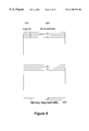
- FIG. 8 is a block diagram showing the details of the segmented reusable video memory design (or named as Rolling Memory Design by the inventors).
- FIG. 9 shows the details of the initialization of the display segment list for each picture.
- FIG. 10 shows the writing of the decoded video data of each macroblock row to the video memory.
- FIG. 11 shows the details of the updating of the display segment list.
- FIG. 12 shows three preferred embodiments of the FlexiRam design.
- FIGS. 13 a , 13 b and 13 c show another three preferred embodiments of the FlexiRam design.
- FIG. 14 is a block diagram showing the steps of the video data compression and decompression.
- FIG. 15 shows the video data format of a quartet during different steps of the compression and decompression.
- the present invention will be described in terms of several preferred embodiments.
- the preferred embodiments are an apparatus and method for handling and processing video data.
- the following three aspects of the present invention will be discussed in detail: (1) Split Video Memory Manager; (2) Segmented Reusable Memory Design (or named by the inventors as “Rolling Memory Design”); and (3) Simple Fixed Low Bitrate Auxiliary Compression Technique without Considering the Methods and Usages (or named by the inventors as “FlexiRam”). All of these three aspects of the present invention are disclosed for the efficient handling of the video memory data and can be implemented in a single video decode and display system.
- FIG. 1 shows a convention video decode and display system comprising, a decoder 110 , a memory manager 120 , a video memory 130 , and a display subsystem 140 .
- a continuous bitstream of coded video data is provided to the decoder 110 for decoding and displaying.
- the continuous bitstream of video data is provided in a constant or a variable bitrate, depending on the overall system design.
- the decoder 110 decompresses the bitstream and then provides the decompressed data to the memory manager 120 .
- the memory manager 120 is responsible for storing the decompressed video data in the video memory 130 and providing the video data for the display subsystem 140 .
- the video memory 130 serves basically two main functions: First, it acts as a video data buffer to buffer the processing speed different between the decoding of the incoming bitstream of video data and the displaying of the decoded video images. To prevent any interruption in displaying the video images, the decoder 110 is generally required to decompress video data faster than the need from the displaying subsystem 140 . Secondly, the video memory 130 is needed to store and provide the reference frames data (i.e. I and P frames) for the decoder 110 to reconstruct the video images from the incoming bitstream of data. Therefore, as indicated in FIG. 1, the data bus between the decoder 110 and the memory manager 120 is bidirectional so that the decompressed data is flowing to and from the memory manager 120 .
- the reference frames data i.e. I and P frames
- FIG. 2 illustrates a novel split memory manager design disclosed by the present invention.
- the memory manager of the present invention comprises two separate memory managers: first memory manager 210 and second memory manager 220 .
- Each of the memory managers is coupled to a video memory (i.e. first memory 230 and second memory 240 ).
- reference frames data i.e. I and P frames
- bidirectional frames data i.e. B frame
- the first memory manager 210 and the coupling first memory 230 is assigned to handle and store the reference frames (i.e. I and P frames) data
- the second memory manager 220 and the coupling second memory 240 is assigned to handle and store the bidirectional frames (i.e. B frames) data.
- each of the two controllers can be specifically designed to implement the most efficient memory management and/or compression methods to handle each kind of video data.
- the present invention provides unsurpassed advantages over the conventional video decode and display system of having a simpler system design while being able to handle the video data more efficiently.
- the memory management method is directed to the B frames.
- the split Memory Manager design it can be designed that only the second memory manager 220 or 320 and the accompanying second memory 240 or 340 implement the Cismas memory management technique; whereas the first memory manager 210 or 310 and the accompanying first memory 230 or 330 performs the conventional video memory management functions. Therefore, the present invention's ability to customize a specific video memory management technique for each kind of video data provides the video system designer with great design flexibility over the conventional design.
- the present invention comprises three memory managers.
- the first memory manager handles I frames.
- the second manager handles P frames.
- the third memory manager handles B frames only.
- the present invention comprises three memory managers.
- Each of the three memory managers handles one of the three color components (e.g. Y, U, and V).
- each of the memory managers can handle a different combination of the types (e.g. color components) and/or groups (e.g. reference frames or bidirectional frames) of the video data.
- a video decode and display system comprises a first memory manager for handling the Y chroma component for I pictures, a second memory manager for handling the U and V chroma components for B pictures, a third memory manager for handling the U and V chroma for I and P pictures, and a fourth memory manager for handling the remaining video data.
- Each of the four memory managers can utilize a different memory management technique.
- the design flexibility provided by the split memory manager design of the present invention is almost unlimited so that each memory manager can be customized to fit a specific kind or definition of the video data.
- FIG. 3 shows another preferred embodiment of the present invention.
- the repeat-first-field is not allowed for the B frames for the PAL standard. Therefore, in the preferred embodiment designed for the MPEG-2 Main Profile Main Level PAL system, the repeat-first-field is not necessary to be provided to the second memory manager 320 because the second memory manager 320 processes only the B frame pictures. However, the top-field-first signal is still required for both the first memory manager 310 and the second memory manager 320 for handling interlaced pictures.
- Another aspect of the present invention is directed to a method of handling video memory allocation for a video decode and display system capable of handling both Field-pictures and Frame-pictures.
- MPEG-2 provides a choice of two Picture Structures for interlaced pictures.
- Field-pictures consists of individual fields that are each divided into macroblocks and coded separately.
- Frame-pictures on the other hand, each interlaced field pair is interleaved together into a frame that is then divided into macroblocks and coded.
- MPEG-2 requires interlaced video to be displayed as alternate top and bottom fields. However, within a frame either the top or bottom field can be temporally coded first and sent as the first Field-picture of the frame according to a predefined definition. Because of the difference in sequence of the decoded data for the two Picture Structures, the writing and reading of the video data defined by these two formats is performed in two different orders.
- FIG. 4 illustrates a preferred embodiment of the present invention.
- the video memory 410 is partitioned into a plurality of memory segments. Each of the memory segment is able to store 8 consecutive lines of video data of one of the two fields.
- the memory manager creates and maintains two lists, MS (Memory Segments) 420 and DS (Display Segments) 430 . Each of the memory segments is indirectly addressed by an entry of the Display Segment list 430 through an entry of the Memory Segment list 420 .
- the MS list 420 has the same number of entries as the video memory segments, and each entry of the MS list corresponds to one memory segment. In a preferred embodiment, the MS list 420 has 48 entries for addressing 48 memory segments in the video memory 410 .
- Each entry of the MS list 420 includes a 20-bits address defining the first cell address of the memory segment in the video memory 410 .
- These addresses can be either static or dynamic, depending on the system design. For example, in a dedicated system specifically designed for decoding and displaying MPEG-2 video data, the addresses are preferably static and not dynamic in order to reduce system overhead. However, in a multi-purposes digital decode and display system such as system capable of displaying both MPEG-1 and MPEG-2 video data, these addresses are preferably dynamically maintained in order to accommodate different video memory management methods.
- the DS list 430 maps the video memory 410 to the display screen.
- the display screen is logically divided into multiple segments, and each entry of the DS list 430 corresponds to one segment of the displaying screen.
- each entry of the MS list 420 includes one additional busy bit 510 (“busy bit”) to indicate whether the particular memory segment of the video memory is busy or not. Specifically, a memory segment is indicated as busy if it was written to and has not been displayed. Similarly, a not busy memory segment means that the memory segment has been displayed and no new data is contained therein.
- the use of the busy bit 510 is very important for the present invention because the switching of the busy bits 510 on each of the entries in the MS list 420 can be characterized as defining a logical sliding window in the video memory 410 .
- the logical sliding window is defined as all the memory segments with the corresponding entries in the MS list with busy bits “on.”
- the logical sliding window is also maintained by the incrementing and updating of two DS write pointers (i.e. 710 and 720 , OR 730 and 740 ) and the read pointer (i.e. 750 OR 760 ) as shown in FIG. 7 .
- the logical sliding window is defined by contiguous entries within the DS list 430 .
- the logical sliding window expands in size after more decoded data are stored in the memory segments in the video memory 410 , whereas the size is decreased after decoded data are read from the memory segments in the video memory 410 .
- the logical sliding window shifts in location (i.e. downwardly in the DS list 430 ) when the video data is read and written from and to the video memory.
- the key concept of the present invention is the ability to define a logically contiguous memory space corresponding to a portion of the display screen that the corresponding decoded video data are currently written to video memory and has not been displayed, even though the video data might be randomly stored in the physical video memory.
- the advantage of the present invention is that the size of the physical video memory can be less than a full picture. Theoretically, the physical memory size can be as little as half of the size needed to store a full picture (i.e. one half of a frame).
- FIG. 4 illustrates the indirect addressing scheme used by the preferred embodiment of the present invention.
- Each entry of the DS list 430 stores an index pointing to an entry of the MS list 420 , whereby each entry of the MS list 420 stores an address of a memory segment of the video memory 410 .
- the video decode and display system of the present invention handles interlaced pictures in both the Frame-picture format and Field-picture format. Therefore, as shown in FIG. 6, the DS list 430 is logically partitioned into two portions: a top portion 610 corresponding to the top field, and a bottom portion 620 corresponding to the bottom field. Entries indexed 0 to 35 belong to the top field and entries indexed 36 to 71 belong to the bottom field. To match the DS list 430 to the corresponding video memory segment 420 , each entry of the DS list 430 includes a 6 bits index (0 to 47) into the MS list 420 . Thereby, each of the entry of the DS list 430 refers to an entries of the MS list 420 and indirectly addressing one segment of the video memory (see FIG. 4 ).
- three pointers are maintained for the DS list 430 : one read pointer for the reading and displaying (i.e. 750 or 760 ), and two write pointers for the video memory writing (i.e. 710 , 720 or 730 , 740 ).
- these three DS pointers are assigned in different positions.
- FIG. 7 ( a ) shows the positions of these three pointers when the video system is handling a Frame-pictures.
- the two write pointers 710 , 720 are set to pointing at two DS entries having an interval of 36 between them so that each of the two write pointers is pointing at an entry in the same offset location in different fields (i.e. the top field, and the bottom field).
- the read pointer 750 is pointing to an entry of the DS list 430 to be displayed next.
- the logical sliding window is further comprises of a logical top window and a logical bottom window.
- the logical top window defines a sliding window in the top field which is indicated by contiguous entries in the top portion of the DS list indirectly addressing to memory segments in the video memory which were written to and has not been displayed.
- the logical bottom window defines a sliding window in the bottom field which is indicated by contiguous entries in the bottom portion of the DS list indirectly addressing to memory segments in the video memory which were written to and has not been displayed.
- FIG. 7 ( b ) shows the positions of these pointers when the video decode and display system is handling Field-pictures. Because the video data of Field-pictures are decoded and provided by the decoder in sequential order, the two write pointers 730 , 740 are set to have a fixed interval of 1 between them. Further, the read pointer 760 is pointing to an entry of the DS list 430 to be displayed next. In the Field-pictures the video data are decoded and provided in sequential order, there is no need to split the logical sliding window further to the logical top and bottom windows as in the Frame-pictures. Therefore, a logical sliding window as discussed in the previous paragraphs is maintained.
- FIG. 8 illustrates a flow diagram for the present invention.
- all the busy bits of the MS entries are initialized to NOT busy (i.e. setting all the busy bits of the MS entries to a logic zero) by the memory manager (step 810 ).
- the memory manager When the memory manager detects a new picture in the incoming stream of coded video data, the memory manager initializes the DS list 430 (step 820 ) as shown in FIG. 9 .
- FIG. 9 details the steps of initializing the DS list 430 for each picture (step 820 ).
- the memory controller checks the format of the picture in the incoming bitstream and determine whether the picture is a Field-picture or a Frame-picture by checking the alue of the Picture_structure parameter (step 910 ).
- the memory controller checks the variable top-field-first to determine whether the flag is set (step 930 ). If a top field is to be decoded first, the DS read pointer 750 is initialized to 36, and the first DS write pointer 710 is set to 0, and the second DS write pointer 720 is set to 36 (step 960 ). On the other hand, if the bottom field is to be decoded first, the DS read pointer 750 is set to 0, the first DS write pointer 710 is set to 0, and the second DS write pointer 720 is set to 36 (step 970 ).
- the memory controller checks the Picture_structure parameter to determine whether the incoming video data is a top field picture or a bottom field picture (step 920 ). If a top field is to be decoded, the three DS pointers are set as follows: DS read pointer 760 is set to 36, the first DS write pointer 730 is set to 0 , and the second DS write pointer 740 is set to 1 (step 940 ). On the other hand, if the bottom field is to be decoded, the DS read pointer 760 is set to 0, the first DS write pointer 730 is set to 36, and the second DS write pointer 740 is set to 37 (step 950 ).
- the memory manager scans the MS list 420 for available space in the video memory 410 by checking the busy bits 510 of the MS list 420 entries (step 830 ).
- the memory manager scans the MS list 420 , in order, from index 0 to index 47, to find the first two entries with the busy bits 510 not set. If there are no such “not busy” segments, or only one such segment, the decoding is stalled until the condition is fulfilled.
- the decoder is thereby entered into a waiting stage waiting for the two “not busy” video memory segments.
- the memory manager will release the memory segments to store the newly decoded video data, when the data in the video memory segments is read and displayed, by setting the corresponding busy bits 510 of the memory segments to a logic zero.
- the MS index 420 (e.g. 0,1,2, . . . or 47) of the first available memory segment is written to the DS list 430 entry pointed at by the first DS write pointer (i.e. 710 or 730 ), and the MS index of the second available memory segment is written to the DS entry pointed at by the second DS write pointer (i.e. 720 or 740 ) so that the two DS write pointers are indirectly addressing the two “not busy” memory segments in the video memory 410 .
- the first DS write pointer i.e. 710 or 730
- the MS index of the second available memory segment is written to the DS entry pointed at by the second DS write pointer (i.e. 720 or 740 ) so that the two DS write pointers are indirectly addressing the two “not busy” memory segments in the video memory 410 .
- the decoder decodes a new macroblock row containing 16 lines of video data (step 830 ).
- the memory manager saves the decoded video data to the video memory in step 840 .
- FIG. 10 shows the details of step 840 .
- the memory manager writes the video data of the top 8 lines of each macroblock row to the memory segment addressed by the entry of the MS segment indirectly addressed by the first DS write pointer 730 (step 1030 ). Then the memory manager writes the video data of the bottom 8 lines of each macroblock row to the memory segment addressed by the entry of the MS segment indirectly addressed by the second DS write pointer 740 (step 1030 ).
- the memory manager writes the 8 lines of the video data corresponding to the top field of the currently decoding frame to the memory segment addressed by the entry of the first MS segment indirectly addressed by the first DS write pointer 710 . Then the memory manager writes the 8 lines of the video data corresponding to the bottom field of the currently decoding frame to the memory segment addressed by the entry of the second MS segment indirectly addressed by the second DS write pointer 720 (step 1020 ).
- the DS pointers i.e. 710 , 720 ,& 750 or 730 , 740 ,& 760
- the DS pointers are then updated (step 860 ) by the steps as shown in FIG. 11 .
- FIG. 11 shows the details of the DS pointers (i.e. 710 , 720 ,& 750 or 730 , 740 & 760 ) updating operations (step 860 ).
- the memory manager first checks whether the video data is in the Field-picture format or Frame-picture format (step 1110 ), then the memory manager updates the two DS write pointers accordingly (steps 1120 & 1130 ).
- both two DS write pointers 710 , 720 are advanced by 1 (step 1120 ).
- both two DS write pointers 730 , 740 are advanced by 2 (step 1130 ).
- the memory manager checks whether there is any more incoming video data for the current picture. If there is still incoming video bitstream, the operation goes back to the MS list scanning stage as shown in FIG. 8 (step 870 ).
- the video system checks whether there is any more pictures for further decoded and displayed (step 880 ). If there are more pictures incoming for decoding and displaying, the whole operation returns to step 820 . The entire operation is completed if there are not any more incoming pictures for displaying (step 890 ).
- the next 8 lines of data is retrieved from the memory segment of the video memory 410 using the MS index addressed by the DS read pointer (i.e. 750 or 760 ).
- the address stored in the MS list entry is used to locate the memory segment to be displayed next from the video memory 410 .
- the busy bit 510 of that MS entry 420 is set to not busy and the DS read pointer is then incremented by 1 (modulo 72 ).
- the DS read pointer is reset to the “0” position after the pointer reaches 71.
- the entries of the DS list 430 can then be increased from 6 bits to 26 bits so that when the address of the memory segment is selected in the MS entry, it is copied to the DS entry together with the MS list 420 index.
- Another aspect of the present invention is directed to an intraframe video memory compression/decompression method.
- the video data is compressed, lossy or lossless, before it is stored in the video memory, and the compressed data will be decompressed when it reads out from the video memory.
- This video data compression and decompression apparatus is named by the inventors as “FlexiRam.”
- FIG. 12 shows three different embodiments of the present invention.
- the FlexiRam 1220 a of the present invention is incorporated into the memory manager 1210 a so that all the compression and decompression of the video data are performed within the memory manager 1210 a .
- the advantages of this embodiment are that there is no special hardware requirement for the video memory 1230 a , and both the compression and decompression of the video data are transparent to the video memory 1230 a.
- FIG. 12 ( b ) shows another preferred embodiment of the present invention, the FlexiRam 1220 b is separated from both the memory manager 1210 b and the video memory 1230 b .
- the advantage of this embodiment is being able to implement the present invention without substantial modifications to the entire video decode and display system.
- FIG. 12 ( c ) shows another embodiment of the present invention, the FlexiRam 1220 c is incorporated into the video memory 1230 c .
- the advantage of this embodiment is the entire operation of the data compression and decompression is transparent to the memory manager 1210 c and no overhead is added to the memory manager 1210 c .
- the present invention works on all picture types (I, P and B) and does not limit itself into any type of pictures. Therefore, if desired, the present invention can be implemented with either (a) the second memory manager 240 ; or (b) both of the first memory manager 230 and the second memory manager 240 in the Split Memory Manager design (see FIG. 2 ).
- FIGS. 13 a , 13 b and 13 c show three different embodiments of the present invention combining the FlexiRam design and the split memory manager design.
- FIG. 13 a shows one of the two preferred embodiments of the present invention. In this embodiment, two FlexiRam compressor/decompressor are used. The first FlexiRam 1370 a is positioned between the First Memory Manager 1310 a and the First Memory 1330 a . The second FlexiRam 1380 a is positioned between the Second Memory Manager 1320 a and the Second Memory 1340 a so that all stored video memory data are compressed and decompressed using the FlexiRam technique.
- FIG. 13 b shows another embodiment of the present invention.
- the FlexiRam 1370 b is positioned between the Second Memory Manager 1320 b and the Second Memory 1340 b so that only video data for the bidirectional frames (i.e. B) are compressed when stored in the video memory.
- FIG. 13 c shows yet another embodiment of the present invention.
- the FlexiRam 1370 c is positioned between the First Memory Manager 1310 c and the First Memory 1330 c so that only video data for the prediction frames (i.e. 2I; 1I and 1P; or 2P) are compressed when stored in the video memory.
- the memory manager can be split to a number (i.e. greater than 3) of separate memory managers to process different types and/or groups of video data.
- the FlexiRam design can be applied to compress and decompress either all three color components or just 2 chroma color components.
- the design can be further improved by combining all these above disclosed embodiments and aspects. For example, in one embodiment, only the U and V color components in a B picture are compressed by the FlexiRam design. Or, in another embodiment, all the three color components for all the two picture groups (i.e. reference frames, or bidirectional frames) are compressed by the FlexiRam design.
- FIG. 14 summarizes a preferred embodiment of the FlexiRam design.
- the data compression comprises 2 steps: (1) error diffusion (step 1410 ); and (2) drop One pixel per quartet (step 1420 ).
- the video data is compressed according to an error diffusion algorithm (step 1410 ).
- the basic compression unit is defined as a “quartet” which includes four consecutive horizontal pixels.
- the error diffusion compression step (step 1410 ) separately compresses each pixel of a quartet. Using a one-bit error diffusion algorithm, a quartet of pixels originally having 32 bits (4 pixels*8 bits/pixel) is compressed to 28 bits (4 pixels*7 bits/pixel). Note that this invention does not limit to the one-bit error diffusion algorithm, multiple-bits error diffusion algorithm can be implemented similarly, however, with a tradeoff of loss in perceptible picture quality.
- the second step of the video data compression is the “drop one pixel per quartet” (step 1420 ).
- the drop one pixel per quartet algorithm compresses a quartet of four 7-bits pixels to a 24-bits quartet.
- the data compressor calculates the best pixel of a quartet to be dropped and stores the reconstruction method in the last three bits of the quartet as the reconstruction descriptor (“RD”).
- RD reconstruction descriptor
- the compressed quartet of pixels has 24 bits (3 pixels*7 bits/pixel+3 bits RD). Detailed algorithm of this drop one pixel per quartet will be described later.
- the FlexiRam When the video data is needed from the video memory, the FlexiRam performs decompression to the compressed data read from the memory.
- the decompression steps are the inverse of the compression steps as shown in FIG. 14 .
- a pixel is added back to each 24-bits quartet by the reconstruct one pixel per quartet algorithm which is the inverse of the drop one pixel per quartet algorithm (step 1430 ).
- This decompression step reconstructs the 7-bits dropped pixel according to the reconstruction method provided by the RD stored as the last three bits of the 24 bits representing the quartet.
- the quartet is reformed to have a four 7-bits pixels.
- a preferred reconstruction algorithm will be described in detail later.
- each of the 7-bits pixels is then concatenated with a “0” to return to the pre-compressed four 8-bits pixels quartet (step 1440 ).
- This decompression step (step 1440 ) concatenates a “0” to every pixel as the least significant bit to reform the four 8-bits pixels.
- FIG. 15 illustrates the data format of a quartet (i.e. four 8-bits pixels) of video data during the different processes in the steps of compression and decompression.
- each of the 8-bits pixel of a quartet 1510 is individually compressed using an error diffusion algorithm 1520 .
- the intermediate compressed data comprises four 7-bits pixels 1530 .
- the four 7-bits pixels 1530 are further compressed by the drop one pixel per quartet algorithm 1540 .
- the final compressed data comprises three 7-bits pixels 1551 and a 3-bits RD 1552 .
- the total length of the compressed data is 24 bits.
- the compressed data is decompressed by the following two consecutive steps.
- an additional pixel is generated according to the Reconstruct One Pixel per quartet algorithm 1560 which is the inverse of the drop one pixel per quartet algorithm 1540 based on the 3-bits RD 1552 of the 24-bits compressed data 1550 .
- the intermediate decompressed data 1570 comprises four 7-bits pixels. Then, each of the four 7-bits pixels concatenates with a “0” as the least significant bit 1580 so the pre-compressed four 8-bits pixels are reformed.
- error diffusion algorithms can be used for this compression step.
- the following disclosed preferred embodiment utilizes a one-bit error diffusion algorithm.
- the present invention is not limited to any specific algorithm used for the error diffusion process.
- multiple bits can be eliminated by the error diffusion algorithm if more degradation in the picture quality is allowed. Therefore, the following particular one-bit error diffusion algorithm is disclosed for illustration purposes only.
- the error diffusion (ED) algorithm works on every line in the picture independently.
- a 1-bit register denoted as “e” is set to one.
- “e” stores the current running error and is updated on a pixel base.
- the one-bit ED algorithm is described by the following two equations:
- I out ( j ) 2*floor[(I in ( j )+ e ( j ))/2]
- j the index of the current pixel in the row.
- I out (j) the new value of the pixel (after ED).
- e(j) the error accumulator at the time of pixel j.
- the least significant bit of I out (j) is dropped so that this algorithm quantizes the 8-bits pixels into 7-bits pixels, while eliminating false contour effects.
- the I in (j) is 182, binary 10010111, and e(j) is 1:
- Iout( j ) 2*floor ((10010111+1)/2)
- the “e” value is then propagated to the end of the line. Since the ED algorithm of the present invention works on a raster structure and pictures are written to memory in block structure, it is necessary to store e(j) at the end of a block line. This value is used when the ED continues with the next pixel in the same line (which belongs to another block). Therefore, an 8-bits latch must be used for every “discontinued” block. (e can only be 0 or 1, so 1-bit per every discontinued line is sufficient.).
- the decompression step 1580 is the inverse of the abovementioned compression step.
- the data is concatenated with “0” to every pixel to reform four 8-bits pixels.
- Each of the 7-bits pixels is then concatenated with a “0” as the least significant bit. For example, a “1101101” will be reformed to a “11011010”. Therefore, the resulting data is a four 8-bits pixels as with the original uncompressed data.
- the present invention discloses a two steps compression/decompression process: (1) One-bit error diffusion; and (2) drop one pixel per quartet.
- the resulting picture quality after the two steps compression and decompression process disclosed as the present invention provides perceptible improvement over the two-bits error diffusion technique even though the compression rates of the two techniques are identical (i.e. 75%).
- the second compression step of the preferred embodiment of the present invention is the drop one pixel per quartet method.
- the drop one pixel per quartet algorithm 1540 compresses a four 7-bits pixels to three 7-bits pixels plus 3 bits reconstruction descriptor (“RD”) (i.e. 24 bits total).
- RD reconstruction descriptor
- pixels dropping algorithms can be used for reducing the number of pixels stored in the video memory.
- the present invention is not limited to any specific pixels dropping algorithms and equations used during the compression and decompression processes.
- multiple pixels can be dropped with a tradeoff of the degradation in picture quality.
- the following drop one pixel per quartet is disclosed as the preferred embodiment of the present invention with the best balance of the memory saved with little perceptible effect on the picture quality.
- each of the four pixels of a quartet is named as P0, P1, P2, or P3 consecutively.
- Pixels P1 and P2 are the two candidates to be dropped.
- the algorithm predicts (1) which pixel is the better one to drop and (2) what reconstruction method should be used in the decompression to estimate the dropped pixel.
- dropping P1 and estimating it by copying P2 is equivalent to dropping P2 and estimating it by copying P1.
- the target size of the final compressed data for each quartet is 24 bits (25% compression). This means that only 3 bits can be allocated to describe the selected estimator, thus only 8 estimators can actually be considered.
- the estimator that is omitted out of consideration is reconstructing P2 by 3 ⁇ 4 of the left neighbor and 1 ⁇ 4 of the right neighbor. The reason for omitting this particular estimator is that statistics of MPEG pictures show that it is the least probable to be chosen as the best one (among the four 1 ⁇ 4, 3 ⁇ 4 estimators the choice is arbitrary).
- P 0 1 P0 (P k i denotes the estimator of Pi using method k )
- E k i
- the minimal error is found: min i,k ⁇ E k 1 ⁇ . If there is more than one minimal error, the choice is arbitrary. (Decision is left open for the implementation).
- P imin is dropped and a 3-bits reconstruction descriptor (RD) is set to indicate the selected estimator, P kmin imin .
- the 3-bits RD is concatenated to the three 7-bits remaining pixels, forming together a 24-bits compressed quartet. The method of concatenation is left open for implementation.
- the decompression of the compressed data is simply the inverse of the compression algorithm.
- the missing 7-bits dropped pixel is reconstructed using the RD at the end of each quartet to select (1) which pixel for reconstruction (i.e. P1 or P2); and (2) which reconstruction method for reconstruction.
- the data decompressor obtains the reconstruction method provided by the three bits of RD. Then the pixel for reconstruction is determined (P1 or P2) and the pixel reconstruction is performed according to the inverse of the eight equations as discussed above.
- the present invention is not limited to any specific methods and equations used in the video data compression steps of the (1) error diffusion, and (2) pixel dropping.
- the key feature of the FlexiRam design disclosed as the present invention is the specific sequence of these two data compression/decompression steps: the video data is first compressed by reducing the number of bits per pixel using an error diffusion algorithm. Then, the intermediate compressed video data is further compressed using a pixel dropping algorithm to drop a pixel(s) among a specific group of pixels.
- the decompression process is just the inverse of the compression process.
Abstract
Description
Claims (52)
Priority Applications (1)
| Application Number | Priority Date | Filing Date | Title |
|---|---|---|---|
| US08/993,796 US6198773B1 (en) | 1997-12-18 | 1997-12-18 | Video memory management for MPEG video decode and display system |
Applications Claiming Priority (1)
| Application Number | Priority Date | Filing Date | Title |
|---|---|---|---|
| US08/993,796 US6198773B1 (en) | 1997-12-18 | 1997-12-18 | Video memory management for MPEG video decode and display system |
Publications (1)
| Publication Number | Publication Date |
|---|---|
| US6198773B1 true US6198773B1 (en) | 2001-03-06 |
Family
ID=25539949
Family Applications (1)
| Application Number | Title | Priority Date | Filing Date |
|---|---|---|---|
| US08/993,796 Expired - Lifetime US6198773B1 (en) | 1997-12-18 | 1997-12-18 | Video memory management for MPEG video decode and display system |
Country Status (1)
| Country | Link |
|---|---|
| US (1) | US6198773B1 (en) |
Cited By (31)
| Publication number | Priority date | Publication date | Assignee | Title |
|---|---|---|---|---|
| US6473464B1 (en) * | 1998-08-07 | 2002-10-29 | Thomson Licensing, S.A. | Method and apparatus for processing video pictures, especially for false contour effect compensation |
| US20030053540A1 (en) * | 2001-09-11 | 2003-03-20 | Jie Wang | Generation of MPEG slow motion playout |
| US6765625B1 (en) * | 1998-03-09 | 2004-07-20 | Divio, Inc. | Method and apparatus for bit-shuffling video data |
| US20040264579A1 (en) * | 2003-06-30 | 2004-12-30 | Sandeep Bhatia | System, method, and apparatus for displaying a plurality of video streams |
| US20050053157A1 (en) * | 2003-09-05 | 2005-03-10 | Lillevold Karl O. | Parallel video decoding |
| US20050083218A1 (en) * | 2003-09-07 | 2005-04-21 | Microsoft Corporation | Signaling for field ordering and field/frame display repetition |
| US20050100093A1 (en) * | 2003-09-07 | 2005-05-12 | Microsoft Corporation | Signaling field type information |
| US20050099869A1 (en) * | 2003-09-07 | 2005-05-12 | Microsoft Corporation | Field start code for entry point frames with predicted first field |
| US20050123274A1 (en) * | 2003-09-07 | 2005-06-09 | Microsoft Corporation | Signaling coding and display options in entry point headers |
| US20050135783A1 (en) * | 2003-09-07 | 2005-06-23 | Microsoft Corporation | Trick mode elementary stream and receiver system |
| US20050152457A1 (en) * | 2003-09-07 | 2005-07-14 | Microsoft Corporation | Signaling and repeat padding for skip frames |
| US20050152448A1 (en) * | 2003-09-07 | 2005-07-14 | Microsoft Corporation | Signaling for entry point frames with predicted first field |
| US20050213665A1 (en) * | 2004-03-25 | 2005-09-29 | Hiroshi Kyusojin | Image decoder and image decoding method and program |
| US20060002475A1 (en) * | 2004-07-02 | 2006-01-05 | Fuchs Robert J | Caching data for video edge filtering |
| US20060274200A1 (en) * | 2005-05-31 | 2006-12-07 | Kabushiki Kaisha Toshiba | Decoder and method for decoding bit stream |
| US20070116112A1 (en) * | 2002-05-31 | 2007-05-24 | Polycom, Inc. | System and method for decreasing end-to-end delay during video conferencing session |
| US7236204B2 (en) | 2001-02-20 | 2007-06-26 | Digeo, Inc. | System and method for rendering graphics and video on a display |
| US20070237231A1 (en) * | 2006-03-29 | 2007-10-11 | Portalplayer, Inc. | Method and circuit for efficient caching of reference video data |
| US7573529B1 (en) | 1999-08-24 | 2009-08-11 | Digeo, Inc. | System and method for performing interlaced-to-progressive conversion using interframe motion data |
| US7680185B2 (en) | 2003-09-07 | 2010-03-16 | Microsoft Corporation | Self-referencing bi-directionally predicted frames |
| US20100220793A1 (en) * | 2007-10-19 | 2010-09-02 | Jang Euee-Seon | Bitstream decoding device and method |
| CN101208954B (en) * | 2004-03-08 | 2010-09-08 | Nxp股份有限公司 | Video decoder with scalable compression and buffer for storing and retrieving reference frame data and decoding method |
| US7839930B2 (en) | 2003-11-13 | 2010-11-23 | Microsoft Corporation | Signaling valid entry points in a video stream |
| US20110026593A1 (en) * | 2009-02-10 | 2011-02-03 | New Wei Lee | Image processing apparatus, image processing method, program and integrated circuit |
| US20110158310A1 (en) * | 2009-12-30 | 2011-06-30 | Nvidia Corporation | Decoding data using lookup tables |
| US20110173167A1 (en) * | 2003-07-17 | 2011-07-14 | Binh Dao Vo | Method and apparatus for windowing in entropy encoding |
| CN101005620B (en) * | 2004-09-03 | 2011-08-10 | 微软公司 | Innovations in coding and decoding macroblock and motion information for interlaced and progressive video |
| US8599841B1 (en) * | 2006-03-28 | 2013-12-03 | Nvidia Corporation | Multi-format bitstream decoding engine |
| US20140177710A1 (en) * | 2012-12-20 | 2014-06-26 | Hitachi Information & Telecommunication Engineering, Ltd. | Video image compression/decompression device |
| US20160150247A1 (en) * | 2014-11-26 | 2016-05-26 | Ning Lu | System and method of compensating for image compression errors |
| WO2017183889A1 (en) | 2016-04-22 | 2017-10-26 | Samsung Electronics Co., Ltd. | A method for enabling processing of a video stream and a device thereof |
Citations (18)
| Publication number | Priority date | Publication date | Assignee | Title |
|---|---|---|---|---|
| USRE31460E (en) | 1978-01-18 | 1983-12-06 | British Broadcast Corporation | Method and apparatus for standards conversion of television signals |
| US4435792A (en) | 1982-06-30 | 1984-03-06 | Sun Microsystems, Inc. | Raster memory manipulation apparatus |
| JPH0651282A (en) | 1992-07-31 | 1994-02-25 | Canon Inc | Display control device |
| US5343248A (en) | 1991-07-26 | 1994-08-30 | Sony Corporation | Moving image compressing and recording medium and moving image data encoder and decoder |
| US5363138A (en) | 1991-10-30 | 1994-11-08 | Fuji Photo Film Co., Ltd. | Image signal reproducing apparatus for partially reproducing image to be displayed |
| US5386233A (en) | 1993-05-13 | 1995-01-31 | Intel Corporation | Method for efficient memory use |
| US5513301A (en) | 1993-11-22 | 1996-04-30 | Nec Corporation | Image compression and decompression apparatus with reduced frame memory |
| US5561465A (en) | 1993-03-31 | 1996-10-01 | U.S. Philips Corporation | Video decoder with five page memory for decoding of intraframes, predicted frames and bidirectional frames |
| US5581310A (en) * | 1995-01-26 | 1996-12-03 | Hitachi America, Ltd. | Architecture for a high definition video frame memory and an accompanying data organization for use therewith and efficient access therefrom |
| US5635985A (en) | 1994-10-11 | 1997-06-03 | Hitachi America, Ltd. | Low cost joint HD/SD television decoder methods and apparatus |
| EP0778709A1 (en) | 1995-12-04 | 1997-06-11 | STMicroelectronics S.r.l. | MPEG-2 decoding with a reduced RAM requisite by ADPCM recompression before storing MPEG decompressed data |
| US5646693A (en) | 1994-11-04 | 1997-07-08 | Cismas; Sorin | Memory utilization for video decoding and display with 3:2 pull-down |
| EP0794675A2 (en) | 1996-03-04 | 1997-09-10 | Kokusai Denshin Denwa Kabushiki Kaisha | Apparatus for decoding coded video data |
| US5668599A (en) | 1996-03-19 | 1997-09-16 | International Business Machines Corporation | Memory management for an MPEG2 compliant decoder |
| US5675387A (en) * | 1994-08-15 | 1997-10-07 | General Instrument Corporation Of Delaware | Method and apparatus for efficient addressing of DRAM in a video decompression processor |
| EP0825781A2 (en) | 1996-08-22 | 1998-02-25 | Matsushita Electric Industrial Co., Ltd. | Image processor |
| EP0843485A2 (en) | 1996-11-13 | 1998-05-20 | Lsi Logic Corporation | MPEG decoder unified memory |
| US6104876A (en) * | 1995-06-07 | 2000-08-15 | Cirrus Logic, Inc. | PCI bus master retry fixup |
-
1997
- 1997-12-18 US US08/993,796 patent/US6198773B1/en not_active Expired - Lifetime
Patent Citations (18)
| Publication number | Priority date | Publication date | Assignee | Title |
|---|---|---|---|---|
| USRE31460E (en) | 1978-01-18 | 1983-12-06 | British Broadcast Corporation | Method and apparatus for standards conversion of television signals |
| US4435792A (en) | 1982-06-30 | 1984-03-06 | Sun Microsystems, Inc. | Raster memory manipulation apparatus |
| US5343248A (en) | 1991-07-26 | 1994-08-30 | Sony Corporation | Moving image compressing and recording medium and moving image data encoder and decoder |
| US5363138A (en) | 1991-10-30 | 1994-11-08 | Fuji Photo Film Co., Ltd. | Image signal reproducing apparatus for partially reproducing image to be displayed |
| JPH0651282A (en) | 1992-07-31 | 1994-02-25 | Canon Inc | Display control device |
| US5561465A (en) | 1993-03-31 | 1996-10-01 | U.S. Philips Corporation | Video decoder with five page memory for decoding of intraframes, predicted frames and bidirectional frames |
| US5386233A (en) | 1993-05-13 | 1995-01-31 | Intel Corporation | Method for efficient memory use |
| US5513301A (en) | 1993-11-22 | 1996-04-30 | Nec Corporation | Image compression and decompression apparatus with reduced frame memory |
| US5675387A (en) * | 1994-08-15 | 1997-10-07 | General Instrument Corporation Of Delaware | Method and apparatus for efficient addressing of DRAM in a video decompression processor |
| US5635985A (en) | 1994-10-11 | 1997-06-03 | Hitachi America, Ltd. | Low cost joint HD/SD television decoder methods and apparatus |
| US5646693A (en) | 1994-11-04 | 1997-07-08 | Cismas; Sorin | Memory utilization for video decoding and display with 3:2 pull-down |
| US5581310A (en) * | 1995-01-26 | 1996-12-03 | Hitachi America, Ltd. | Architecture for a high definition video frame memory and an accompanying data organization for use therewith and efficient access therefrom |
| US6104876A (en) * | 1995-06-07 | 2000-08-15 | Cirrus Logic, Inc. | PCI bus master retry fixup |
| EP0778709A1 (en) | 1995-12-04 | 1997-06-11 | STMicroelectronics S.r.l. | MPEG-2 decoding with a reduced RAM requisite by ADPCM recompression before storing MPEG decompressed data |
| EP0794675A2 (en) | 1996-03-04 | 1997-09-10 | Kokusai Denshin Denwa Kabushiki Kaisha | Apparatus for decoding coded video data |
| US5668599A (en) | 1996-03-19 | 1997-09-16 | International Business Machines Corporation | Memory management for an MPEG2 compliant decoder |
| EP0825781A2 (en) | 1996-08-22 | 1998-02-25 | Matsushita Electric Industrial Co., Ltd. | Image processor |
| EP0843485A2 (en) | 1996-11-13 | 1998-05-20 | Lsi Logic Corporation | MPEG decoder unified memory |
Non-Patent Citations (7)
| Title |
|---|
| Article extracted from Website: Chiariglione, L., "MPEG and Multimedia Communications," CSELT-Torino, Italy. |
| Article extracted from Website: Fogg, C. MPEG-2 FAQ Question that Should be Frequently Asked About MPEG, version 3.8 (Apr. 2, 1996). |
| Article extracted from Website: VideoDiscovery, DVD Frequently Asked Questions (with answers!), written and maintained by Jim Taylor. |
| Cantineau, O., et al., "Architecture of a Memory Managaer for an MPEG-2 Video Decoding Circuit," Journal of VLSI Signal Processing, vol. 20, pp. 251-265 (1998). |
| Fox, S.J., et al., "Multiple Error Correction Algorithm For Halftone, Continuous Tone and Text Reproduction," IBM Technical Disclosure Bulletin, vol. 23, No. 10 , (Mar. 1981) pp. 4433-4435. |
| International Organisation for Standardisation Organisation Internationale de Normalisation , ISO/IEC 13818-2, Coding of Moving Pictures ns Associated Audio, ISO/IEC JTC1/SC29/WG11 N0702(revised), Incorporating N702 Delta of Mar. 24, and Further Editorial Corrections May 10, 1994. |
| Text Book: Haskell, B.G., et al., "Digital Video: An Introduction to MPEG-2," Chapman & Hall, copyright 1997. |
Cited By (50)
| Publication number | Priority date | Publication date | Assignee | Title |
|---|---|---|---|---|
| US6765625B1 (en) * | 1998-03-09 | 2004-07-20 | Divio, Inc. | Method and apparatus for bit-shuffling video data |
| US6473464B1 (en) * | 1998-08-07 | 2002-10-29 | Thomson Licensing, S.A. | Method and apparatus for processing video pictures, especially for false contour effect compensation |
| US7573529B1 (en) | 1999-08-24 | 2009-08-11 | Digeo, Inc. | System and method for performing interlaced-to-progressive conversion using interframe motion data |
| US7236204B2 (en) | 2001-02-20 | 2007-06-26 | Digeo, Inc. | System and method for rendering graphics and video on a display |
| US6980594B2 (en) * | 2001-09-11 | 2005-12-27 | Emc Corporation | Generation of MPEG slow motion playout |
| US20030053540A1 (en) * | 2001-09-11 | 2003-03-20 | Jie Wang | Generation of MPEG slow motion playout |
| US20070116112A1 (en) * | 2002-05-31 | 2007-05-24 | Polycom, Inc. | System and method for decreasing end-to-end delay during video conferencing session |
| US20040264579A1 (en) * | 2003-06-30 | 2004-12-30 | Sandeep Bhatia | System, method, and apparatus for displaying a plurality of video streams |
| US8200680B2 (en) * | 2003-07-17 | 2012-06-12 | At&T Intellectual Property Ii, L.P. | Method and apparatus for windowing in entropy encoding |
| US20110173167A1 (en) * | 2003-07-17 | 2011-07-14 | Binh Dao Vo | Method and apparatus for windowing in entropy encoding |
| US20050053157A1 (en) * | 2003-09-05 | 2005-03-10 | Lillevold Karl O. | Parallel video decoding |
| US7627039B2 (en) | 2003-09-05 | 2009-12-01 | Realnetworks, Inc. | Parallel video decoding |
| US8116380B2 (en) * | 2003-09-07 | 2012-02-14 | Microsoft Corporation | Signaling for field ordering and field/frame display repetition |
| US20050135783A1 (en) * | 2003-09-07 | 2005-06-23 | Microsoft Corporation | Trick mode elementary stream and receiver system |
| US20050083218A1 (en) * | 2003-09-07 | 2005-04-21 | Microsoft Corporation | Signaling for field ordering and field/frame display repetition |
| US20050100093A1 (en) * | 2003-09-07 | 2005-05-12 | Microsoft Corporation | Signaling field type information |
| US20050152448A1 (en) * | 2003-09-07 | 2005-07-14 | Microsoft Corporation | Signaling for entry point frames with predicted first field |
| US20050152457A1 (en) * | 2003-09-07 | 2005-07-14 | Microsoft Corporation | Signaling and repeat padding for skip frames |
| US8107531B2 (en) | 2003-09-07 | 2012-01-31 | Microsoft Corporation | Signaling and repeat padding for skip frames |
| US7924921B2 (en) | 2003-09-07 | 2011-04-12 | Microsoft Corporation | Signaling coding and display options in entry point headers |
| US7609762B2 (en) | 2003-09-07 | 2009-10-27 | Microsoft Corporation | Signaling for entry point frames with predicted first field |
| US20050123274A1 (en) * | 2003-09-07 | 2005-06-09 | Microsoft Corporation | Signaling coding and display options in entry point headers |
| US20050099869A1 (en) * | 2003-09-07 | 2005-05-12 | Microsoft Corporation | Field start code for entry point frames with predicted first field |
| US7680185B2 (en) | 2003-09-07 | 2010-03-16 | Microsoft Corporation | Self-referencing bi-directionally predicted frames |
| US7961786B2 (en) | 2003-09-07 | 2011-06-14 | Microsoft Corporation | Signaling field type information |
| US8213779B2 (en) * | 2003-09-07 | 2012-07-03 | Microsoft Corporation | Trick mode elementary stream and receiver system |
| US7852919B2 (en) | 2003-09-07 | 2010-12-14 | Microsoft Corporation | Field start code for entry point frames with predicted first field |
| US7839930B2 (en) | 2003-11-13 | 2010-11-23 | Microsoft Corporation | Signaling valid entry points in a video stream |
| CN101208954B (en) * | 2004-03-08 | 2010-09-08 | Nxp股份有限公司 | Video decoder with scalable compression and buffer for storing and retrieving reference frame data and decoding method |
| US20050213665A1 (en) * | 2004-03-25 | 2005-09-29 | Hiroshi Kyusojin | Image decoder and image decoding method and program |
| US7639743B2 (en) * | 2004-03-25 | 2009-12-29 | Sony Corporation | Image decoder and image decoding method and program |
| US20060002475A1 (en) * | 2004-07-02 | 2006-01-05 | Fuchs Robert J | Caching data for video edge filtering |
| CN101005620B (en) * | 2004-09-03 | 2011-08-10 | 微软公司 | Innovations in coding and decoding macroblock and motion information for interlaced and progressive video |
| US20060274200A1 (en) * | 2005-05-31 | 2006-12-07 | Kabushiki Kaisha Toshiba | Decoder and method for decoding bit stream |
| US8599841B1 (en) * | 2006-03-28 | 2013-12-03 | Nvidia Corporation | Multi-format bitstream decoding engine |
| US8593469B2 (en) | 2006-03-29 | 2013-11-26 | Nvidia Corporation | Method and circuit for efficient caching of reference video data |
| US20070237231A1 (en) * | 2006-03-29 | 2007-10-11 | Portalplayer, Inc. | Method and circuit for efficient caching of reference video data |
| US8687704B2 (en) * | 2007-10-19 | 2014-04-01 | Humax Co., Ltd. | Bitstream decoding device and method |
| US20100220793A1 (en) * | 2007-10-19 | 2010-09-02 | Jang Euee-Seon | Bitstream decoding device and method |
| US20110026593A1 (en) * | 2009-02-10 | 2011-02-03 | New Wei Lee | Image processing apparatus, image processing method, program and integrated circuit |
| US20110158310A1 (en) * | 2009-12-30 | 2011-06-30 | Nvidia Corporation | Decoding data using lookup tables |
| US20140177710A1 (en) * | 2012-12-20 | 2014-06-26 | Hitachi Information & Telecommunication Engineering, Ltd. | Video image compression/decompression device |
| US9509992B2 (en) * | 2012-12-20 | 2016-11-29 | Hitachi Information & Telecommunication Engineering, Ltd. | Video image compression/decompression device |
| US20160150247A1 (en) * | 2014-11-26 | 2016-05-26 | Ning Lu | System and method of compensating for image compression errors |
| US10080028B2 (en) * | 2014-11-26 | 2018-09-18 | Samsung Display Co., Ltd. | System and method of compensating for image compression errors |
| WO2017183889A1 (en) | 2016-04-22 | 2017-10-26 | Samsung Electronics Co., Ltd. | A method for enabling processing of a video stream and a device thereof |
| US10034026B2 (en) * | 2016-04-22 | 2018-07-24 | Akila Subramaniam | Device for and method of enabling the processing of a video stream |
| CN108886624A (en) * | 2016-04-22 | 2018-11-23 | 三星电子株式会社 | For realizing the method for video flow processing and the equipment of realization video flow processing |
| KR20180128916A (en) * | 2016-04-22 | 2018-12-04 | 삼성전자주식회사 | Method and apparatus for enabling processing of video streams |
| EP3414909A4 (en) * | 2016-04-22 | 2019-03-13 | Samsung Electronics Co., Ltd. | A method for enabling processing of a video stream and a device thereof |
Similar Documents
| Publication | Publication Date | Title |
|---|---|---|
| US6198773B1 (en) | Video memory management for MPEG video decode and display system | |
| US5847762A (en) | MPEG system which decompresses and then recompresses MPEG video data before storing said recompressed MPEG video data into memory | |
| US5835636A (en) | Method and apparatus for reducing the memory required for decoding bidirectionally predictive-coded frames during pull-down | |
| EP0843485B1 (en) | Video decoder with unified memory | |
| US6996174B2 (en) | MPEG video decoder with integrated scaling and display functions | |
| US6473558B1 (en) | System and method for MPEG reverse play through dynamic assignment of anchor frames | |
| US6104416A (en) | Tiling in picture memory mapping to minimize memory bandwidth in compression and decompression of data sequences | |
| US6088391A (en) | Method and apparatus for segmenting memory to reduce the memory required for bidirectionally predictive-coded frames | |
| US6983017B2 (en) | Method and apparatus for implementing reduced memory mode for high-definition television | |
| US6301304B1 (en) | Architecture and method for inverse quantization of discrete cosine transform coefficients in MPEG decoders | |
| US20070030911A1 (en) | Method and apparatus for skipping pictures | |
| US20120076208A1 (en) | Memory reduced h264/mpeg-4 avc codec | |
| US5739862A (en) | Reverse playback of MPEG video | |
| US6028612A (en) | Picture memory mapping to minimize memory bandwidth in compression and decompression of data sequences | |
| JP2011505780A (en) | An extension of the AVC standard to continuously encode high-resolution digital still images with video | |
| US6480542B1 (en) | Method for decoding compressed video data with a reduced memory requirement | |
| EP1383339A1 (en) | Memory management method for video sequence motion estimation and compensation | |
| US6163576A (en) | Video encoder having reduced memory bandwidth requirements | |
| EP0782341A2 (en) | Image data compression system | |
| US7436889B2 (en) | Methods and systems for reducing requantization-originated generational error in predictive video streams using motion compensation | |
| JP2898413B2 (en) | Method for decoding and encoding compressed video data streams with reduced memory requirements | |
| CA2491868A1 (en) | A method of managing reference frame and field buffers in adaptive frame/field encoding | |
| JP4486755B2 (en) | Video memory management for MPEG video decoding and display system | |
| US6144323A (en) | Method and apparatus for decoding video data | |
| EP1758403A2 (en) | Video memory management for MPEG video decode and display system |
Legal Events
| Date | Code | Title | Description |
|---|---|---|---|
| AS | Assignment |
Owner name: ZORA CORPORATION, CALIFORNIA Free format text: ASSIGNMENT OF ASSIGNORS INTEREST;ASSIGNORS:GILL, AHARON;ROSENTHAL, ELAN;FRAENKEL, MIRI;AND OTHERS;REEL/FRAME:009329/0926;SIGNING DATES FROM 19980526 TO 19980615 |
|
| STCF | Information on status: patent grant |
Free format text: PATENTED CASE |
|
| FPAY | Fee payment |
Year of fee payment: 4 |
|
| FPAY | Fee payment |
Year of fee payment: 8 |
|
| REMI | Maintenance fee reminder mailed | ||
| AS | Assignment |
Owner name: CSR TECHNOLOGY INC., CALIFORNIA Free format text: ASSIGNMENT OF ASSIGNORS INTEREST;ASSIGNOR:ZORAN CORPORATION;REEL/FRAME:027550/0695 Effective date: 20120101 |
|
| FPAY | Fee payment |
Year of fee payment: 12 |
|
| AS | Assignment |
Owner name: CSR TECHNOLOGY INC., CALIFORNIA Free format text: ASSIGNMENT OF ASSIGNORS INTEREST;ASSIGNOR:ZORAN CORPORATION;REEL/FRAME:036642/0395 Effective date: 20150915 |
|
| AS | Assignment |
Owner name: CSR TECHNOLOGY INC., CALIFORNIA Free format text: CORRECTIVE ASSIGNMENT TO CORRECT THE ASSIGNEE NAME PREVIOUSLY RECORDED AT REEL: 027550 FRAME: 0695. ASSIGNOR(S) HEREBY CONFIRMS THE ASSIGNMENT;ASSIGNOR:ZORAN CORPORATION;REEL/FRAME:037089/0011 Effective date: 20120101 |
|
| FEPP | Fee payment procedure |
Free format text: PAYOR NUMBER ASSIGNED (ORIGINAL EVENT CODE: ASPN); ENTITY STATUS OF PATENT OWNER: LARGE ENTITY Free format text: PAYER NUMBER DE-ASSIGNED (ORIGINAL EVENT CODE: RMPN); ENTITY STATUS OF PATENT OWNER: LARGE ENTITY |