US6191905B1 - Magnetic disc apparatus - Google Patents
Magnetic disc apparatus Download PDFInfo
- Publication number
- US6191905B1 US6191905B1 US09/265,853 US26585399A US6191905B1 US 6191905 B1 US6191905 B1 US 6191905B1 US 26585399 A US26585399 A US 26585399A US 6191905 B1 US6191905 B1 US 6191905B1
- Authority
- US
- United States
- Prior art keywords
- window
- magnetic disc
- error rate
- setting
- recording
- Prior art date
- Legal status (The legal status is an assumption and is not a legal conclusion. Google has not performed a legal analysis and makes no representation as to the accuracy of the status listed.)
- Expired - Lifetime
Links
Images


Classifications
-
- G—PHYSICS
- G11—INFORMATION STORAGE
- G11B—INFORMATION STORAGE BASED ON RELATIVE MOVEMENT BETWEEN RECORD CARRIER AND TRANSDUCER
- G11B19/00—Driving, starting, stopping record carriers not specifically of filamentary or web form, or of supports therefor; Control thereof; Control of operating function ; Driving both disc and head
- G11B19/02—Control of operating function, e.g. switching from recording to reproducing
- G11B19/04—Arrangements for preventing, inhibiting, or warning against double recording on the same blank or against other recording or reproducing malfunctions
-
- G—PHYSICS
- G11—INFORMATION STORAGE
- G11B—INFORMATION STORAGE BASED ON RELATIVE MOVEMENT BETWEEN RECORD CARRIER AND TRANSDUCER
- G11B20/00—Signal processing not specific to the method of recording or reproducing; Circuits therefor
- G11B20/10—Digital recording or reproducing
- G11B20/18—Error detection or correction; Testing, e.g. of drop-outs
- G11B20/1816—Testing
- G11B20/182—Testing using test patterns
-
- G—PHYSICS
- G11—INFORMATION STORAGE
- G11B—INFORMATION STORAGE BASED ON RELATIVE MOVEMENT BETWEEN RECORD CARRIER AND TRANSDUCER
- G11B27/00—Editing; Indexing; Addressing; Timing or synchronising; Monitoring; Measuring tape travel
- G11B27/36—Monitoring, i.e. supervising the progress of recording or reproducing
-
- G—PHYSICS
- G11—INFORMATION STORAGE
- G11B—INFORMATION STORAGE BASED ON RELATIVE MOVEMENT BETWEEN RECORD CARRIER AND TRANSDUCER
- G11B5/00—Recording by magnetisation or demagnetisation of a record carrier; Reproducing by magnetic means; Record carriers therefor
- G11B5/012—Recording on, or reproducing or erasing from, magnetic disks
Definitions
- the present invention relates to a magnetic disc apparatus and in particular, to a magnetic disc apparatus for producing a pulse of a reproduction signal within a window.
- a peak shift phenomenon can be seen. That is, a reproduction signal has a peak not stable and shifted.
- the range allowed for this peak shift is called a window margin, indicating the character of data read/write performance.
- the window margin is adjusted in accordance with the performance of a magnetic disc medium. There have been suggested various methods to adjust this window margin according to a magnetic disc position or for respective heads.
- Japanese Patent Publication (unexamined) A3-95773 [1] discloses a method in which a multi-phase window is generated so as to select a window having an optimal phase difference with respect to a data signal.
- Japanese Patent Publication (unexamined) A9-180373 [2] filed by the same applicant as the present invention discloses a method of setting this window margin as follows. That is, a window position is shifted firstly in the plus direction and the minus direction, so as to determine error rates at the shifted positions. Next, a window margin is set according to the value of the error rate.
- the window position is modified at a constant interval and measurement is performed only once at each of the measurement points. Accordingly, when the same optimization is performed, there is a case that an optimal value is obtained at a position different from the previous optimization.
- each of the error rates for calculating the window margin is measured only once at each window shift (WSF) point where the error rate easily fluctuates and that the optimization program including the window margin measurement is a procedure for varying one point in each parameter with an identical interval (step).
- Another object of the present invention is to provide a magnetic disc apparatus capable of performing a window shift margin measurement with a higher accuracy and at a higher speed than in the conventional magnetic disc apparatus.
- the magnetic disc apparatus comprises: a magnetic disc for recording a data; a reproduction head for reproducing a data recorded on the magnetic disc; and a signal processor for shaping a reproduction signal reproduced by the reproduction head and generating a pulse from the reproduction signal by using an optimized window.
- the signal processor includes: (i) means for setting measurement points at an interval which is smaller in the vicinity of an initial position of a window than in the vicinity of the maximum modification position; (ii) means for shifting the window from the initial position up to the maximum modification position; (iii) means for reproducing a check data recorded on the magnetic disc so as to measure an error rate each time the window position is shifted according to the aforementioned interval; and (iv) means for using the error rate measurement results to obtain an optimal position of the window.
- the region associated with the window margin position is checked accurately to obtain a high accuracy, while the region not affecting the optimization of the window margin position is checked roughly to reduce the time required for the check.
- FIG. 1 is a functional block diagram schematically showing a configuration of a magnetic disc apparatus according to an embodiment of the present invention.
- FIG. 2 is a flowchart showing an operation example of the configuration of FIG. 1 .
- FIG. 3 is a block diagram showing a configuration of hardware resources of the magnetic disc apparatus of FIG. 1 .
- FIG. 4 is a block diagram showing a detailed configuration of a signal processor shown in FIG. 3 .
- FIG. 5 is a block diagram showing an example of a window position and width optimization by the configuration shown in FIG. 3 .
- FIG. 6 is a graph showing an example of margin curve obtained by the processing shown in FIG. 2 or FIG. 5 (Calculating method of present invention).
- FIG. 7 is a graph showing another example of margin curve obtained when performing no measurement position adjustment or no average value calculation (Calculating method of prior art).
- FIG. 8 is a flowchart showing a parameter setting procedure according to an embodiment of the present invention.
- FIG. 9 is a flowchart showing a former stage of a detailed processing of the bit shift correction ( 1 ) shown in FIG. 8 .
- FIG. 10 is a flowchart showing a latter stage of a detailed processing of the bit shift correction ( 1 ) shown in FIG. 8 .
- FIG. 11 explains in a layered expression the parameter modification procedure by the processing shown in FIG. 9 and FIG. 10 .
- FIG. 11A shows a processing at the Early side and
- FIG. 11B shows a processing at the Late side.
- FIG. 12 is a flowchart showing a former stage of a detailed processing of the bit shift correction ( 2 ) shown in FIG. 8 .
- FIG. 13 is a flowchart showing an intermediate stage of a detailed processing of the bit shift correction ( 2 ) shown in FIG. 8 .
- FIG. 14 is a flowchart showing a latter stage of a detailed processing of the bit shift correction ( 2 ) shown in FIG. 8 .
- FIG. 15 explains in a layered expression the parameter modification procedure by the processing shown in FIG. 12 to FIG. 14 .
- FIG. 15A shows a Boost setting
- FIG. 15B shows an fc setting
- FIG. 15C shows a write pre-compensation setting.
- FIG. 1 is a functional block diagram schematically showing a configuration of a magnetic disc apparatus according to an embodiment of the present invention.
- the magnetic disc apparatus includes: a magnetic disc 1 for recording a data; a reproduction head (recording/reproduction head) 3 for reproducing the data recorded on a magnetic disc 1 ; and a signal processor 5 for shaping a reproduction signal reproduced by the reproduction head 3 and adjusting a recording signal.
- the signal processor 5 employs a window at an optimal position to produce a pulse from the reproduction signal.
- the signal processor 5 includes: window position adjustment means 7 for varying the window position from a window initial position to a maximum modification position; error rate measurement means 9 for reproducing a check data recorded on the magnetic disc 1 and measuring an error rate for each time when the window position is adjusted by the window position adjustment mean 7 ; window position optimization means 11 for optimizing the window position according to a result of the measurement by the error rate measurement means 9 .
- the window position adjustment means 11 has a measurement point setting function 9 B for setting a plurality of measurement points nearer to the window initial position at a smaller interval than the measurement points nearer to the maximum modification position.
- measurement is performed at a smaller interval (step). This assures to obtain a more preferable window setting.
- measurement is performed at a rough interval. That is, in the region having a large error rate and not required for optimization of the window position, the measurement can be completed in a short time.
- this measurement point setting function preferably has: means for dividing the interval from the window initial position to the maximum modification position into a center region and a peripheral region at a predetermined ratio, and means for setting more measurement points in the center region than in the peripheral region. That is, in this example, two regions are set concerning the measurement interval (step). Moreover, it is also possible to change the measurement point interval in three or more stages.
- the window position adjustment means sets twice more measurement points in the center region than in the peripheral region. This enables to set measurement points at a smaller interval in the region required for setting the window position. On the other hand, in the peripheral region, measurement points are set at a greater interval. Thus, it is possible to perform the window position setting at a high speed with a high accuracy.
- the error rate measurement means 9 have an average value calculation function 9 A for performing a plurality of measurements at each measurement point in the center region and calculating an average of the error rate for each measurement point.
- this function enables to obtain a smooth graph (hereinafter, referred to as a margin curve). If a window position is determined according to this margin curve, it is possible to set the window position with a high accuracy.
- the window position adjustment means 7 have an error rate plot function for plotting error rates at respective measurement points, from the window initial position to the left side and the right side. From two width values obtained as the two plot results by the error rate plot function, the width of the error rate set as a target error rate is determined to be a window width. This determination is performed by a window width determination function of the window optimization means 11 , which also has a window position determination function for determining as a window position the position where that window width has been obtained.
- the window position adjustment means preferably has an error rate-dependent measurement interval setting function for successively setting measurement points starting at the window initial position and modifying the setting interval according to results of error rate measurement performed in parallel to the measurement point setting.
- the measurement interval may be determined in relation to the error rate or the measurement interval may be increased when the error rate becomes greater than a predetermined error rate.
- an initial value of the window width (window margin) and an initial value of the window center position (window center) are read out (stage A 1 ).
- a range for shifting the window is determined (stage A 2 ). This is determined according to a data density and linear velocity for recording a data on the magnetic disc. Thus, the initial position and the maximum position for the window shifting are determined.
- a measurement pointer is set (stage A 3 ).
- the measurement interval is fine in the vicinity of the initial position and rough in the vicinity of the maximum position.
- the window is shifted to each of the measurement points to measure the error rate (stage A 4 ).
- the window having the width of the initial value is moved in the track direction according the measurement interval and the error rate is measured at each of the measurement points.
- one end of the window is at one measurement point and the other end of the window is at another measurement point.
- FIG. 6 shows an example of the margin curve.
- the horizontal axis represents a window position and the vertical axis represents an error rate.
- the window position is determined so as to have a width from ⁇ 2 to +1. If the error rate of 10 ⁇ 6 is sufficient, the range from ⁇ 3 to +2.5 is used.
- the error rate intersected by the horizontal axis is 0.
- the window margin when the window margin is in the range from ⁇ 2 to +1, the error rate is 0. Accordingly, it is possible to use as the margin curve the section connecting the measurement result at +2 and the measurement result at +3 (as shown by a dotted line in FIG. 6 ). Thus, the window margin satisfying the error rate equal to or below 10 ⁇ 7 is obtained as the range indicated by W 1 in FIG. 6 .
- measurement points are set at a fine interval in the vicinity of the window initial value and an average value is calculated for a measurement point having a large error rate change. This enables to obtain a margin curve of a conical shape, which enables to obtain a stable optimization of the window width and position.
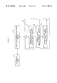
- FIG. 3 is a block diagram showing a configuration of hardware resources of the magnetic disc apparatus according to the present invention.
- the magnetic disc apparatus includes: a magnetic disc 80 ; a recording/reproduction head 90 ; a servo controller 70 for controlling rotation of the magnetic disc 80 and positioning of the recording/reproduction head 90 ; and a read/write IC (chip) 40 for controlling output of a write current (Ic) for recording a data (recording pulse) on the recording/reproduction head and creating a magnetization reversed pulse according to a data read out from a medium.
- the magnetic disc 80 is driven to rotate by a spindle motor.
- the magnetic disc apparatus further includes: an R/W channel LSI 10 as a signal processor; a microprocessor (MPU) 50 for controlling the magnetic disc apparatus; and a hard disc controller (HDC) 60 for input/output of instructions and data which are output from a host computer 100 .
- R/W channel LSI 10 as a signal processor
- MPU microprocessor
- HDC hard disc controller
- the magnetic disc may employ any of the conventional servo methods, zone setting, and zone allocation on the magnetic disc.
- the window setting is preferably optimized for each of the zones.
- FIG. 4 shows a detailed configuration of the R/W channel LSI including: a parameter register 11 for setting parameters for respective blocks; an active filter (FLT) 12 for shaping a reproduction signal waveform; a peak detector (SLV-CTL) for controlling the reproduction signal slice level (threshold value for producing a pulse); and a data synchronizer (DT-SYC) 14 for controlling the window width and position to define a range for producing a pulse.
- FLT active filter
- SLV-CTL peak detector
- DT-SYC data synchronizer
- the R/W channel LSI includes: a synthesizer (TBG) for creating a write PLO clock; an encoder (ENC) 16 for converting a data from the hard disc controller (HDC) into a recording code; a decoder (DEC) 17 for converting the recording code into a data; and a write pre-compensation (WPC) 18 for controlling timing when the write pulse is changed according to the recording code pattern.
- TCG synthesizer
- EEC encoder
- DEC decoder
- WPC write pre-compensation
- the R/W channel LSI includes: a servo demodulator (SC-DEM) for detecting an information for head positioning on the disc medium surface; and an automatic gain apparatus (AGC) 20 for stabilizing the amplitude value of the read out signal supplied from the RWC 10 .
- SC-DEM servo demodulator
- AGC automatic gain apparatus
- the window position adjustment means 7 , the error rate measurement means 9 , and the window position optimization means 11 shown in FIG. 1 are realized as circuits such as the data synchronizer and control by the MPU. Distribution of the functions between the LSI and the MPU with a program may be designed or modified depending on the type of the magnetic disc apparatus.
- FIG. 5 is a flowchart showing an example of processing for optimizing the window position and width.
- the window is shifted in the range from ⁇ 10 to +10.
- FIG. 6 shows a range from ⁇ 7 to +7. Firstly, outside the range of ⁇ 5 from the center, the error rate is measured at a double step width 2 S (stage S 1 ). That is, measurement points far from the window center SO are set at a greater interval than the normal step width. This enables to reduce the number of measurements which do not have a significant effect for the margin calculation.
- the error rate is measured at the normal interval, i.e., step S (stage S 2 ).
- the error rate measurement is terminated both in the plus side and the minus side.
- stage S 3 the error rate measurement is again performed at the points where zero has been obtained and at two points below and above zero points, i.e., both in the plus direction and minus direction (stage S 3 ).
- three points are selected both in the plus direction and minus direction as the points which directly affect the margin calculation.
- the point ⁇ 2 where the error rate has become zero and the two preceding points ⁇ 3 and ⁇ 4 are selected as the three points for re-measurement.
- the point +1 where the error rate has become zero and the two following points +2 and +3 are selected as the three points for the re-measurement.
- the re-measurement is performed once in this embodiment but may also be performed more than once. Moreover, the calculation of the average error rate value may be based on the two points preceding and following the error zero points or on all the points reaching the upper limit.
- the measurement results obtained in the first measurement and the re-measurement are used to obtain an average error rate (stage S 4 ).
- a margin curve is created as shown in FIG. 6, so as to set a window margin according to a predetermined error rate. That is, if the error rate is 10 ⁇ 7 , the window margin is set as a range between ⁇ 2 and +1.5 as shown in FIG. 6 .
- FIG. 7 shows a margin curve obtained by the conventional method.
- the margin curve of FIG. 6 is more smooth, enabling to calculate a window margin with a higher accuracy.
- FIG. 8 is a flowchart showing a parameter setting procedure by the R/W channel LSI (signal processor) according to the present embodiment.
- an analog ETE is executed (C 1 ).
- This step determines a cylinder for which the window margin and the amplitude margin are to be calculated for setting the R/W LSI parameter setting.
- a string shift is performed (C 2 ).
- a group ready setting condition is selected.
- a bit shift correction ( 1 ) is performed (C 3 ) o as to select (temporary setting) of a setting condition of a write pre-compensation (Early, Late). Furthermore, a bit shift correction ( 2 ) is performed (C 4 )
- the temporary setting of C 3 is used to select a setting condition of the filter (fc, Boost) and write pre-compensation.
- the amplitude margin is measured (C 5 ).
- the slice level and the filter (fc, Boost setting condition is selected.
- the write current setting is performed (C 6 ).
- the parameters selected in steps C 2 to C 6 are loaded (C 7 ).
- FIG. 9 and FIG. 10 are a flowchart showing a procedure to obtain a condition for Early direction addition and Late direction addition of write pre-compensation amounts. Note that FIG. 9 is continuous to FIG. 10 at symbols A and B.
- bit shift correction In the bit shift correction ( 1 ), firstly, the LSI is initialized (Bl). The group ready (GDLY) is set It is assumed that the slice level and the filter (fc, Boost) are at their center values, the write current is set to its minimum value, the write pre-compensation is 0. These values are stored in the parameter register 11 shown in FIG. 4 .
- a bit shift worst pattern is written on the magnetic disc 80 (B 2 ).
- the worst pattern is a 3 T pattern followed by a continuous two-bit pattern having different bit intervals.
- the worst pattern is written while changing only the Early side or Late side of the setting of the write pre-compensation (WPC) 18 .
- WPC write pre-compensation
- This worst pattern is recorded and reproduced so as to optimize the window width and position allowing fluctuation of the reproduction signal peak position. It is also possible that this worst pattern is recorded on a part of the magnetic disc in advance.
- the window margin at the target error rate E 1 is determined to calculate the center value C 2 (B 3 a to B 3 e ).
- the cross “x” indicates error rates obtained in the first and the second measurements
- the circle “o” indicates the average of the error rates of the first and the second measurements at measurement points ⁇ 2, ⁇ 3, ⁇ 4 and +1, +2, +3.
- no error occurred (error rate e 1 ).
- the window margin W 3 at the error rate E 1 is calculated
- FIG. 11 shows this write pre-compensation amount in a layered form.
- FIG. 12 to FIG. 14 are a flowchart showing a processing of the bit shift correction ( 2 ) for retrieving a filter fc/Boost setting condition according to the group ready value and the write pre-compensation value. Note that FIG. 12 . FIG. 13, and FIG. 14 are continuous at points C, D, E, and F.
- the step S 1 for the window margin specification setting determines a reference to accept or not accept a check result.
- the GDLY and WPC values (G 1 , ELY 1 , LTE 1 ) selected and calculated in step C 3 is loaded in the parameter register 11 .
- the bit shift worst pattern write D 3 prepares a write pattern identical to the one used in the bit shift correction ( 1 ), and the WPC 18 setting is written onto the magnetic disc.
- the window margin at the error rate E 1 is determined to calculate the margin width W 3 .
- the filter (fc/Boost) maximum check D 5 uses an addition (D 8 ) loop from the fc or Boost minimum value to determine the window margin in the range of the fc/Boost.
- the write pre-compensation is performed as an Early direction maximum check (D) and an Early/Late direction addition (D 7 ), where the Early/Late direction addition is performed without changing the sum wpc of the Early and Late of the WPC calculated in the bit shift correction ( 1 ).
- the window margin is determined in the range of the fc/Boost setting.
- Step D 9 extracts a maximum window margin (W 3 x ) in the entire range of the WPC, FLT, and fc/Boost.
- Step S 10 performs a window margin specification evaluation by comparing the W 3 x with a window margin specification value (K 1 ). If the W 3 x is equal to or greater than K 1 , the window margin is accepted. Otherwise, the window margin is not accepted.
- step D 11 When the window margin is decided to be acceptable, step D 11 performs a window center calculation to determine the center value C 3 of the window margin W 3 x .
- Step D 12 selects a WPC at w 3 x by selecting ELY 2 and LTE 2 for the Early and Late, respectively.
- step D 13 for filter selection for W 3 x the fc and Boost select fc 2 and BST 2 , respectively, passing control to the next chapter (C 5 ).
- step S 14 when the window margin is decided to be unacceptable, control is passed to step S 14 for retry check. If the retry fails twice, i.e., if the retry fails after a cylinder zone is shifted twice, step S 18 decides that the head has failed, terminating the parameter setting operation.
- step D 15 for cylinder zone shift the object zone is shifted to an outer cylinder zone having the other parameters unchanged, where the string shift correction retry D 16 and the bit shift correction ( 1 ) retry D 17 are performed. Then, control is returned to D 3 .
- FIG. 15 schematically shows the parameter modification procedure of FIG. 12 to FIG. 15 .
- the measurement points are set at a smaller interval than in the region not affecting the margin calculation. That is, in the conventional measurement program, measurements points are set at an identical interval between the maximum and the minimum values so that the error rate measurement is performed once at each of the points, whereas in the present example the error rate measurement is performed twice or more for a window shift points that significantly affects the window margin width, so as to obtain an average value. This reduces the measurement fluctuation and enables to effectively and accurately estimate the point where the window margin is at a maximum value.
Abstract
Description
Claims (9)
Applications Claiming Priority (2)
| Application Number | Priority Date | Filing Date | Title |
|---|---|---|---|
| JP10-071819 | 1998-03-20 | ||
| JP10071819A JPH11273260A (en) | 1998-03-20 | 1998-03-20 | Magnetic disk device |
Publications (1)
| Publication Number | Publication Date |
|---|---|
| US6191905B1 true US6191905B1 (en) | 2001-02-20 |
Family
ID=13471556
Family Applications (1)
| Application Number | Title | Priority Date | Filing Date |
|---|---|---|---|
| US09/265,853 Expired - Lifetime US6191905B1 (en) | 1998-03-20 | 1999-03-11 | Magnetic disc apparatus |
Country Status (3)
| Country | Link |
|---|---|
| US (1) | US6191905B1 (en) |
| JP (1) | JPH11273260A (en) |
| DE (1) | DE19911460A1 (en) |
Cited By (4)
| Publication number | Priority date | Publication date | Assignee | Title |
|---|---|---|---|---|
| US20030067697A1 (en) * | 2001-10-05 | 2003-04-10 | Weinstein Robert Edward | Anticipating media decay in a disc drive |
| US6631108B1 (en) * | 2000-04-03 | 2003-10-07 | Hewlett-Packard Development Company, L.P. | Method for accurate positioning of data marks and spaces on an optical disc |
| US6654331B1 (en) | 2000-04-03 | 2003-11-25 | Hewlett-Packard Development Company, L.P. | Method for accurate positioning of data marks and spaces on an optical disc |
| US8922922B2 (en) | 2012-07-20 | 2014-12-30 | HGST Netherlands B.V. | Method to reduce written-in errors in storage media |
Families Citing this family (1)
| Publication number | Priority date | Publication date | Assignee | Title |
|---|---|---|---|---|
| JP2001264212A (en) * | 2000-03-14 | 2001-09-26 | Advantest Corp | Waveform measuring device, method and recording medium |
Citations (2)
| Publication number | Priority date | Publication date | Assignee | Title |
|---|---|---|---|---|
| US5760982A (en) * | 1996-02-02 | 1998-06-02 | Guzik Technical Enterprises, Inc. | Method and apparatus for testing magnetic heads and disks |
| US5995305A (en) * | 1993-12-01 | 1999-11-30 | Maxtor Corporation | Disk drive using off-track margin to obtain optimal performance parameters |
-
1998
- 1998-03-20 JP JP10071819A patent/JPH11273260A/en active Pending
-
1999
- 1999-03-11 US US09/265,853 patent/US6191905B1/en not_active Expired - Lifetime
- 1999-03-15 DE DE19911460A patent/DE19911460A1/en not_active Ceased
Patent Citations (2)
| Publication number | Priority date | Publication date | Assignee | Title |
|---|---|---|---|---|
| US5995305A (en) * | 1993-12-01 | 1999-11-30 | Maxtor Corporation | Disk drive using off-track margin to obtain optimal performance parameters |
| US5760982A (en) * | 1996-02-02 | 1998-06-02 | Guzik Technical Enterprises, Inc. | Method and apparatus for testing magnetic heads and disks |
Cited By (7)
| Publication number | Priority date | Publication date | Assignee | Title |
|---|---|---|---|---|
| US6631108B1 (en) * | 2000-04-03 | 2003-10-07 | Hewlett-Packard Development Company, L.P. | Method for accurate positioning of data marks and spaces on an optical disc |
| US6654331B1 (en) | 2000-04-03 | 2003-11-25 | Hewlett-Packard Development Company, L.P. | Method for accurate positioning of data marks and spaces on an optical disc |
| US20040062187A1 (en) * | 2000-04-03 | 2004-04-01 | Wilson Carol J. | Method for accurate positioning of data marks and spaces on an opitcal disc |
| US6813233B2 (en) * | 2000-04-03 | 2004-11-02 | Hewlett-Packard Development Company, L.P. | Method for accurate positioning of data marks and spaces on an optical disc |
| US20030067697A1 (en) * | 2001-10-05 | 2003-04-10 | Weinstein Robert Edward | Anticipating media decay in a disc drive |
| US6898033B2 (en) * | 2001-10-05 | 2005-05-24 | Seagate Technology Llc | Anticipating media decay in a disc drive |
| US8922922B2 (en) | 2012-07-20 | 2014-12-30 | HGST Netherlands B.V. | Method to reduce written-in errors in storage media |
Also Published As
| Publication number | Publication date |
|---|---|
| JPH11273260A (en) | 1999-10-08 |
| DE19911460A1 (en) | 1999-11-18 |
Similar Documents
| Publication | Publication Date | Title |
|---|---|---|
| EP0740830B1 (en) | Disk drive employing adaptive read/write channel for optimizing head-media-channel performance | |
| US5610776A (en) | Method of optimizing read channel of disk drive recording apparatus by using error rate | |
| US5623474A (en) | Disk apparatus having automatic adjustment of adaptive filter equalization parameter using training pattern | |
| US7483234B2 (en) | Control device, control method, and storage apparatus for controlling read head and write head clearance by thermal protrusion | |
| US6115350A (en) | Optical disk having write power adjustment portion | |
| US7263043B2 (en) | Optical disk apparatus for optimizing laser power during recording | |
| US6785074B2 (en) | Preamble pattern and magnetic recording system using the pattern | |
| US6781786B2 (en) | Magnetic disk drive system | |
| CN114141273A (en) | Data storage device defining track trajectories to reduce AC track compression | |
| US6191905B1 (en) | Magnetic disc apparatus | |
| US6618338B1 (en) | Data reproduction control method and apparatus, and optical disk unit | |
| JP3836313B2 (en) | Optical recording method and optical recording apparatus | |
| US7239586B2 (en) | Optical disk device and recording power determining method | |
| US6920280B2 (en) | Digital data play back apparatus and method for playing back digital data | |
| US4774601A (en) | Read channel for magnetic recording | |
| US7817511B2 (en) | Phase difference detection circuit, phase difference detecting method, optical disk drive, and optical disk drive controlling method | |
| GB2423218A (en) | Data storage system read/write channel optimiser which compares measured metrics of read channel with desired nominal and adjusts channel in response | |
| JP3031226B2 (en) | Method for setting R / W channel parameters of magnetic disk drive | |
| JPH05225711A (en) | Setting method of operating parameters for disk recording device | |
| US10482918B1 (en) | Changing bit spacing for selected symbols written to a magnetic recording medium | |
| JP2001518223A (en) | Error correction by programmable bias current of MR recording head | |
| US20080175120A1 (en) | Optical disc apparatus and optical disc recording and reproduction method | |
| JPH06243552A (en) | Tracking controller | |
| JPH11120703A (en) | Method and device for optimizing equalization parameter, and method and device for controlling magnetic disk device using this device | |
| JPH0721504A (en) | Method and device for equal error rate recording |
Legal Events
| Date | Code | Title | Description |
|---|---|---|---|
| AS | Assignment |
Owner name: NEC CORPORATION, JAPAN Free format text: ASSIGNMENT OF ASSIGNORS INTEREST;ASSIGNOR:TAKEUCHI, TOSHIO;REEL/FRAME:009830/0600 Effective date: 19990224 |
|
| FEPP | Fee payment procedure |
Free format text: PAYOR NUMBER ASSIGNED (ORIGINAL EVENT CODE: ASPN); ENTITY STATUS OF PATENT OWNER: LARGE ENTITY Free format text: PAYER NUMBER DE-ASSIGNED (ORIGINAL EVENT CODE: RMPN); ENTITY STATUS OF PATENT OWNER: LARGE ENTITY |
|
| STCF | Information on status: patent grant |
Free format text: PATENTED CASE |
|
| AS | Assignment |
Owner name: TDK CORPORATION, JAPAN Free format text: ASSIGNMENT OF ASSIGNORS INTEREST;ASSIGNOR:NEC CORPORATION;REEL/FRAME:013879/0693 Effective date: 20021227 |
|
| FPAY | Fee payment |
Year of fee payment: 4 |
|
| FPAY | Fee payment |
Year of fee payment: 8 |
|
| FPAY | Fee payment |
Year of fee payment: 12 |