US6185075B1 - Actuator arm assembly for a magnetic storage device - Google Patents
Actuator arm assembly for a magnetic storage device Download PDFInfo
- Publication number
- US6185075B1 US6185075B1 US09/132,009 US13200998A US6185075B1 US 6185075 B1 US6185075 B1 US 6185075B1 US 13200998 A US13200998 A US 13200998A US 6185075 B1 US6185075 B1 US 6185075B1
- Authority
- US
- United States
- Prior art keywords
- pivot
- washer
- head
- alignment
- actuator arm
- Prior art date
- Legal status (The legal status is an assumption and is not a legal conclusion. Google has not performed a legal analysis and makes no representation as to the accuracy of the status listed.)
- Expired - Fee Related
Links
Images


Classifications
-
- G—PHYSICS
- G11—INFORMATION STORAGE
- G11B—INFORMATION STORAGE BASED ON RELATIVE MOVEMENT BETWEEN RECORD CARRIER AND TRANSDUCER
- G11B5/00—Recording by magnetisation or demagnetisation of a record carrier; Reproducing by magnetic means; Record carriers therefor
- G11B5/48—Disposition or mounting of heads or head supports relative to record carriers ; arrangements of heads, e.g. for scanning the record carrier to increase the relative speed
- G11B5/54—Disposition or mounting of heads or head supports relative to record carriers ; arrangements of heads, e.g. for scanning the record carrier to increase the relative speed with provision for moving the head into or out of its operative position or across tracks
- G11B5/55—Track change, selection or acquisition by displacement of the head
- G11B5/5521—Track change, selection or acquisition by displacement of the head across disk tracks
- G11B5/5526—Control therefor; circuits, track configurations or relative disposition of servo-information transducers and servo-information tracks for control thereof
Definitions
- the present invention relates to a method for washing an actuator arm assembly for use with an information recording/reproducing unit such as a magnetic disk storage unit, an actuator arm assembly suitable for the washing method, and an information recording/reproducing unit.
- an information recording/reproducing unit such as a magnetic disk storage unit
- an actuator arm assembly suitable for the washing method and an information recording/reproducing unit.
- FIG. 1 is a plan view of a conventional magnetic disk storage unit 10 .
- a plurality of magnetic disks 11 are stacked at even spacings, mounted on a rotating shaft 19 , and rotated at a fixed rotating speed.
- the magnetic disks use a front and a back side as recording areas respectively.
- An actuator arm assembly 21 hereinafter referred to as comb-type actuator arm assembly) includes a comb-type carriage 14 and a head/suspension assembly having a magnetic head 12 attached thereto is mounted so as to face the magnetic disk, and the rear end of the head/suspension assembly 13 is connected to an arm portion of the comb-type carriage 14 .
- a coil support 22 is formed, and a coil 26 is fixed to the inside of it by a bonding agent.
- a permanent magnet is mounted in a voice coil motor portion 15 , and the coil 26 is held in its magnetic field.
- a lead wire of the coil 26 and the lead wire connected to the magnetic head are connected to a control unit 17 through a flexible cable 16 and a circuit board 20 .
- the control unit 17 feeds a controlled current to the coil 26 to swing the actuator arm assembly about a pivot shaft 18 , thereby for positioning the magnetic head at a predetermined track position on the magnetic disk 11 along the direction indicated by arrow A.
- the flux used in the soldering vaporizes and sticks to the surrounding components. Accordingly, washing the components contaminated by the flux by the soldering is preferred for keeping the environment in the magnetic disk storage unit clean. In particular, this tendency is remarkable in the magnetic disk storage unit having a high recording density.
- a connection of the flexible cable 16 to the lead wire for the head is also provided by solder in the actuator arm assembly, it is preferred to wash the actuator arm assembly wholly after the soldering.
- the actuator arm assembly since the actuator arm assembly includes the pivot 18 as a component and the pivot uses a lubricating oil in its inner bearing, the assembly cannot be immersed wholly in the super-pure water for washing. Accordingly, the washing of the actuator arm assembly needs to be performed after the completion of the soldering and before the mounting of the pivot.
- FIG. 2 is a perspective view of the comb-type actuator arm assembly 21 of the magnetic disk storage unit of FIG. 1.
- a lead wire 31 is drawn out from a head 30 , and soldered to the flexible cable 16 at a portion 32 of a connecting board 24 .
- the lead wire 31 for the head is depicted only for the uppermost head/suspension assembly, and a lead wire is actually drawn out from each head in a similar manner.
- two lead wires 27 and 28 are drawn out and connected to the flexible cable 16 by solder.
- the comb-type carriage 14 is usually integrally molded by aluminum die casting. In the actuator arm assembly 21 shown in FIG.
- stacked actuator arm assembly which does not use the comb-type carriage has been employed.
- a head/suspension assembly is integrally formed from a portion on which a head is to be mounted to a portion to be inserted into a pivot shaft, and they are stacked with spacers sandwiched there between and fixed to the pivot. After the head/suspension assemblies and spacers are fixed to the pivot shaft, the lead wires from the heads and coil are connected to a flexible cable by solder on a connecting board.
- the stacked structure is fixed by screwing the pivot with a nut after aligning the head/suspension assemblies and spacers, but the rotational force of the nut screwed by a wrench may be transmitted to the head/suspension assemblies and spacers by friction to bring them out of alignment. If the alignment of the head/suspension assemblies is broken, the effective region dedicated to the disk recording is decreased, and if the alignment of the spacers is broken, the drive performance of the actuator by the VCM is adversely affected.
- the principle of the present invention resides in that, using a stacked actuator arm assembly having a structure enabling the soldering to be completed before mounting a pivot, the assembly is wholly washed after the completion of the soldering.
- the principle of the present invention also resides in that the pivot and washer are prevented from rotating when the pivot is mounted on the actuator arm assembly.
- a first sub-assembly is formed in which alignment and fixing thereof are made without using a pivot, and a flexible cable is connected to the first sub-assembly by solder or the like to form a second sub-assembly.
- a method for fixing the head/suspension assemblies and the spacers which are stacked for forming the first sub-assembly any method enabling the next soldering process without using the pivot is included in the scope of the present invention, whether it is for temporary fixing only for execution of the present invention or for permanent fixing.
- the second sub-assembly can be wholly immersed in super-pure water or a solvent for washing even if it is contaminated by the connection of the flexible cable with soldering, because the pivot has not been mounted yet. Since the pivot can be mounted in a clean room after the second sub-assembly is washed, a lubricating oil for the pivot cannot be washed out.
- a head portion of the pivot and an outer periphery of the washer have hold portions respectively.
- a thread portion of the pivot is screwed into a nut by a wrench after inserting the pivot into the stacked structure. If the pivot and the washer are held at the each hold portion so that the head portion of the pivot and the hold portion of the washer do not rotate, the alignment of the head/suspension assemblies and spacers is not broken by the frictional force transmitted from the rotation of the nut.
- the shapes of the head portion of the pivot and the hold portion of the washer include all the shapes which enable them to be held by pinching them with a wrench or a jig when the nut is screwed.
- an information recording/reproducing unit which is equipped with the stacked actuator arm assembly, in which the alignment of the head/suspension assemblies and the spacers are reliably maintained when the pivot is mounted.
- FIG. 1 is a plan view of the conventional magnetic disk storage unit
- FIG. 2 is a perspective view of the conventional comb-type actuator arm assembly
- FIG. 3 is an assembly drawing of the first sub-assembly of the stacked actuator arm assembly for use with the present invention
- FIG. 4 is a perspective view of the stacked actuator arm assembly for use with the present invention.
- FIG. 5 is the pivot and washer of the stacked actuator arm assembly for use with the present invention
- FIG. 6 is another embodiment showing the shape of the hold portions.
- FIG. 7 is a figure showing the method for making the stacked actuator arm assembly of the present invention.
- FIG. 3 is an assembly diagram showing a first sub-assembly before obtaining the stacked actuator arm assembly formed as final structure 50 .
- Ten head/suspension assemblies 51 a , 51 b , 51 c , 51 d , 51 e , 51 f , 51 g , 51 h , 51 i and 51 j , four spacers 53 a , 53 b , 53 c , 53 d , and one spacer 54 are shown in the order of stacking. Accordingly, this actuator arm assembly corresponds to five magnetic disks.
- Each head/suspension assembly 51 a , 51 b , 51 c , 51 d , 51 e , 51 f , 51 g , 51 h , 51 i , 51 j has a slider 52 a , 52 b , 52 c , 52 d , 52 e , 52 f , 52 g , 52 h , 52 i , 52 j mounted on a tip thereof, to which a magnetic head is attached, and its rear end 57 is formed in a shape of a ring so that it can be inserted into a pivot shaft.
- the head/suspension assemblies consist of an actuator arm, a load beam, and a flexure, which are respectively formed by a thin plate made of stainless steel, and integrally connected to each other by spot welding.
- a lead wire from the head is formed on the head/suspension assembly 51 as a wiring pattern, and extends to a head terminals 75 a , 75 b , 75 c , 75 d , 75 e , 75 f , 75 g , 75 h , 75 i and 75 j .
- the spacers 53 have the same shape with each other, and their thickness depends on the stack spacing of the magnetic disks.
- the spacer 54 has the same thickness as the spacers 53 and has a coil support 55 , and inside the coil support 55 , a coil 56 is fixed by a bonding agent.
- the first sub-assembly of FIG. 3 has a bolt 74 .
- the bolt 74 passes through the holes formed in the respective head/suspension assemblies 51 and the respective spacers 53 and 54 , and couples with the corresponding thread portion formed in a washer 72 , thereby to integrally form the stacked head/suspension assemblies and the spacers.
- Positions of the holes of the respective head/suspension assemblies 51 and the spacers 54 are determined so that the head/suspension assemblies and the spacer 54 match the position required for the actuator arm assembly formed as the final structure. Since the spacer 53 does not have directivity, the hole position does not have a limitation on alignment as does the spacer 54 .
- FIG. 4 is a perspective view for explaining the final structure of the actuator arm assembly obtained by adding additional parts to the first sub-assembly of FIG. 3 .
- the construction of the actuator arm assembly of FIG. 4 can be obtained by adding two processes to the first sub-assembly depicted in FIG. 3 .
- a connecting board 65 having a flexible cable connected thereto is attached to the spacer 54 by a screw 68 .
- each of head terminals 75 a , 75 b , 75 c , 75 d , 75 e , 75 f , 75 g , 75 h , 75 i and 75 j is soldered to the flexible cable on the connecting board 65 . Since the first sub-assembly is fixed by the bolt 74 after aligned, the soldered connection of the head terminals 75 a , 75 b , 75 c , 75 d , 75 e , 75 f , 75 g , 75 h , 75 i and 75 j is not exposed to stress or peeled off.
- lead wires 62 and 63 from a coil 56 are soldered to the flexible cable 76 on the connecting board 65 to obtain a second sub-assembly.
- the above shown process to obtain the second subassembly represents one embodiment and it is not intended to be limited to this, but the order of the connections of the head terminals 75 a , 75 b , 75 c , 75 d , 75 e , 75 f , 75 g , 75 h , 75 i and 75 j and the lead wires 62 and 63 to the flexible cable 76 may be reversed.
- the second sub-assembly can be wholly immersed into super-pure water for washing.
- the washing of the second sub-assembly by wholly immersing is effective particularly against the contamination from flux, and decreases the possibility that the actuator arm assembly produces particulates within the magnetic disk storage unit.
- the second sub-assembly is moved into a clean room, and a nut 73 is used to fix the second sub-assembly with the pivot 71 .
- the bolt 74 can be removed after the pivot 71 is mounted, it may be left in the final product of the magnetic disk drive in consideration of the risk of the regeneration of particulates from the thread portion after the removal.
- the head portion 77 of the pivot 71 needs to be fixed by some means to prevent the pivot 71 from rotating in the direction in which the nut 73 rotates, but it is not easy to securely inhibit the rotation since the outer periphery of the head portion 77 is circular. If the head portion 77 is not fully held, the head portion 77 rotates as the nut 73 rotates, transmits its rotational force to the uppermost head/suspension assembly 51 in contact with the head portion 77 by friction, and sequentially transmits the rotational force through the spacers and the head/suspension assembly under it. As a result, the head/suspension assembly 51 and the spacer 54 are put out of alignment.
- the rotational force is also transmitted to the washer 72 sandwiched between the nut 73 and the head/suspension assemblies, the alignment of the head/suspension assemblies 51 and the spacer 54 is similarly disturbed.
- the bolt 74 acts to maintain the alignment when the pivot is mounted, but the alignment sometimes cannot be fully maintained if the tightening torque of the nut is large.
- FIG. 5 is an embodiment showing the novel structures of a pivot 80 and a washer 84 for use with the stacked actuator arm assembly, which are employed to solve the above problems.
- hold portions 82 and 85 are formed by cutting away part of a periphery shaped in a circle.
- the hold portions of the pivot 80 and the washer 84 have a structure which enables to be hold easily by a wrench or jig.
- a shape can be provided in which cutouts are formed in a periphery, as shown in FIG. 6, or a polygon like a bolt nut can also be provided.
- a hold portion is formed by partially providing cutout portions to a typical circular shape of a head portion of a pivot and a washer, because degree of change added to the pivot and the washer production is little.
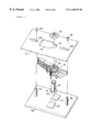
- FIG. 7 is used to describe a method for making the stacked actuator arm assembly in which the pivot and the washer shown in FIG. 5 are used.
- the second sub-assembly 90 depicted in FIG. 4 is reversed with respect to the top and the bottom thereof and mounted on a jig for making the stacked actuator arm assembly.
- the jig consists of a base 100 and a washer holding board 107 .
- the base 100 comprises a holding portion 101 and 102 formed so as to slightly project from a surface of the base for pinching and holding the hold portions 82 formed in the head portion 81 of the pivot 80 , and a support 103 and 104 for supporting the washer holding board 107 .
- the washer holding board 107 there are provided an opening 110 for pinching and holding the hold portions 85 of the washer 84 , and an opening 111 larger than the opening 110 . Further, there are provided an opening 108 and 109 for fixing the washer holding board 107 to the support 103 and 104 by a screw 105 and 106 .
- the second subassembly 90 is fabricated by the above described procedure. Then, the holding portions 82 of the pivot 80 are interposed between the holding portion 101 and 102 of the base 100 with the downward head portion 81 of the pivot 80 . Subsequently, the second sub-assembly 90 is inserted over the pivot 80 upside down. Further, the washer holding board 107 is placed upon the second sub-assembly so that the opening 110 pinches the hold portions 85 of the washer. After the opening 110 pinches the hold portions 85 of the washer, the washer holding board 107 is fixed to the support 103 and 104 by the screw 105 and 106 .
- the nut 86 is placed over the thread portion of the pivot 80 , and screwed by a wrench.
- the pivot 80 is not rotated by the rotational force of the wrench, because the hold portions 82 of the head portion of the pivot are held by the holding portion 101 and 102 .
- the washer 84 does not rotate while the nut 86 is screwed by the wrench, because the hold portions 85 of the washer 84 are held by the opening 110 of the washer holding board 107 . Accordingly, the head/suspension assemblies and the spacers are not put out of alignment while the nut 86 is coupled to the pivot 80 .
- the screw 105 and 106 are loosened, and the washer holding board 107 is rightwardly moved and removed.
- the present invention enabled to provide a method for washing the stacked actuator arm assembly after the completion of soldering.
- the present invention enabled to provide a stacked actuator arm assembly suitable for the above washing, in which a head/suspension assembly is not put out of alignment when the pivot is mounted thereto.
- the present invention enabled to provide a method for fabricating the above actuator arm assembly.
- the present invention enabled to provide an information recording/reproducing unit on which the above stacked actuator arm assembly is mounted, and in which the recording area of a disk is not decreased and the drive performance of the actuator is not reduced.
Abstract
Description
Claims (2)
Applications Claiming Priority (2)
| Application Number | Priority Date | Filing Date | Title |
|---|---|---|---|
| JP9259460A JPH1196528A (en) | 1997-09-25 | 1997-09-25 | Method for washing actuator arm assembly and actuator arm assembly |
| JP9-259460 | 1997-09-25 |
Publications (1)
| Publication Number | Publication Date |
|---|---|
| US6185075B1 true US6185075B1 (en) | 2001-02-06 |
Family
ID=17334384
Family Applications (1)
| Application Number | Title | Priority Date | Filing Date |
|---|---|---|---|
| US09/132,009 Expired - Fee Related US6185075B1 (en) | 1997-09-25 | 1998-08-10 | Actuator arm assembly for a magnetic storage device |
Country Status (2)
| Country | Link |
|---|---|
| US (1) | US6185075B1 (en) |
| JP (1) | JPH1196528A (en) |
Cited By (33)
| Publication number | Priority date | Publication date | Assignee | Title |
|---|---|---|---|---|
| US6369989B1 (en) * | 1999-05-26 | 2002-04-09 | Kazutoshi Yamamoto | Swing arm for magnetic disc |
| US6417986B1 (en) | 1998-11-16 | 2002-07-09 | Samsung Electronics Co., Ltd. | Impact guard for limiting hard disk movement |
| US6417994B1 (en) | 1999-04-22 | 2002-07-09 | Samsung Electronics, Co., Ltd. | Swage plate with protruded walls to increase retention torque in hard disk applications |
| US6446517B1 (en) | 2000-11-20 | 2002-09-10 | Samsung Electronics Company | Controlled particle deposition in drives and on media for thermal asperity studies |
| US6456463B1 (en) * | 2000-02-10 | 2002-09-24 | Hutchinson Technology Incorporated | Actuator assembly having an arm with a spring mount for mounting to an assembly spacer |
| US6501614B1 (en) | 1999-08-19 | 2002-12-31 | Samsung Electronics Co., Ltd. | Acoustic insulator for controlling noise generated in a mass storage device |
| US6525910B1 (en) * | 2000-05-22 | 2003-02-25 | Seagate Technology Llc | Threadably mountable drive actuator bearing assembly |
| US6549372B1 (en) | 1998-12-15 | 2003-04-15 | Samsung Electronics Co., Ltd | Device for limiting head movement within a hard disk drive |
| US6590738B2 (en) | 2001-03-01 | 2003-07-08 | Samsung Electronics Co., Ltd. | Particle removal device in a hard disk drive |
| US20030206366A1 (en) * | 2002-05-06 | 2003-11-06 | Dan Blick | Reaction mass dual-stage actuator (DSA) and sensor |
| US6704161B1 (en) | 1998-11-06 | 2004-03-09 | Samsung Electronics Co. Ltd. | Shock protection skin bumper for a hard disk drive |
| US6738228B2 (en) * | 2000-01-12 | 2004-05-18 | Tdk Corporation | Magnetic head positioner assembly |
| US6744597B2 (en) | 1999-10-29 | 2004-06-01 | Samsung Electronics Co., Ltd. | Dynamic absorber for an actuator arm in a disk drive |
| US20040125506A1 (en) * | 2002-12-30 | 2004-07-01 | Christopher Nguyen | Modular rotary actuator assembly for a rotatable media data storage device |
| US20040123440A1 (en) * | 2002-12-30 | 2004-07-01 | Christopher Nguyen | Methods for assembling or reworking a rotary actuator assembly for a media data storage device |
| US20040123463A1 (en) * | 2002-12-30 | 2004-07-01 | Ramsdell Richard G. | Method for seating a removable bearing assembly in a rotary actuator assembly for a rotatable media data storage device |
| US20040123448A1 (en) * | 2002-12-30 | 2004-07-01 | Christopher Nguyen | Methods for assembling or reworking a modular rotary actuator assembly for a rotatable media data storage device |
| US20040125504A1 (en) * | 2002-12-30 | 2004-07-01 | Ramsdell Richard G. | Removable bearing assembly in a rotary actuator assembly for a rotatable media data storage device |
| WO2004061825A2 (en) * | 2002-12-30 | 2004-07-22 | Ramsdell Richard G | Removable bearing assembly for data storage device |
| US6781796B2 (en) * | 2001-10-18 | 2004-08-24 | Seagate Technology Llc | Counterbalance fastener for a disc drive stacked actuator |
| US20040200889A1 (en) * | 2003-04-11 | 2004-10-14 | Ho Yiu Sing | System and method for improving hard drive actuator lead attachment |
| US20040264060A1 (en) * | 2003-06-26 | 2004-12-30 | Macpherson Aaron Steve | Stacked actuator arm assembly with registration washer |
| US20050223547A1 (en) * | 2004-04-02 | 2005-10-13 | Pfeiffer Michael W | Protecting and merging a head stack assembly of a data storage device |
| US6989970B2 (en) | 2002-12-27 | 2006-01-24 | Matsushita Electric Industrial Co., Ltd. | Rotary actuator assembly for a rotatable media data storage device |
| US7024754B1 (en) * | 2000-10-10 | 2006-04-11 | Maxtor Corporation | Method of assembling an actuator assembly of a disk drive and of reducing torque out retention values in subsequent de-swaging |
| US20060132982A1 (en) * | 2004-12-22 | 2006-06-22 | Hitachi Global Storage Technologies Netherlands B.V. | Disk drive, and actuator and head actuator assembly |
| US20080043373A1 (en) * | 2006-08-15 | 2008-02-21 | Fujitsu Limited | Apparatus for protecting head suspension assembly |
| US8068314B1 (en) | 2009-03-18 | 2011-11-29 | Western Digital Technologies, Inc. | Head stack assembly with suspension tails extending into interfering slits in a flexible printed circuit |
| US8279560B1 (en) | 2009-03-04 | 2012-10-02 | Western Digital Technologies, Inc. | Head stack assembly with suspension tail bond alignment by solder pin |
| US8611052B1 (en) | 2012-03-27 | 2013-12-17 | Western Digital Technologies, Inc. | Systems and methods for aligning components of a head stack assembly of a hard disk drive |
| US8934199B1 (en) | 2014-03-31 | 2015-01-13 | Western Digital Technologies, Inc. | Disk drive head suspension tail with bond pad edge alignment features |
| US9324346B1 (en) | 2008-08-20 | 2016-04-26 | Western Digital Technologies, Inc. | Head stack assembly with a flexible printed circuit having a mouth centered between arms |
| US9330695B1 (en) | 2013-12-10 | 2016-05-03 | Western Digital Technologies, Inc. | Disk drive head suspension tail with a noble metal layer disposed on a plurality of structural backing islands |
Families Citing this family (1)
| Publication number | Priority date | Publication date | Assignee | Title |
|---|---|---|---|---|
| JP4137775B2 (en) * | 2003-12-02 | 2008-08-20 | Tdk株式会社 | Suspension retention pallet |
Citations (8)
| Publication number | Priority date | Publication date | Assignee | Title |
|---|---|---|---|---|
| US5491598A (en) * | 1994-05-06 | 1996-02-13 | Seagate Technology, Inc. | Rotary actuator vibration damper |
| US5550694A (en) * | 1993-07-12 | 1996-08-27 | Western Digital Corporation | Magnetic memory disk storage system |
| US5627702A (en) * | 1995-08-10 | 1997-05-06 | Seagate Technology, Inc. | Head positioner stack for high-capacity disc drives |
| US5654851A (en) * | 1995-07-21 | 1997-08-05 | Read-Rite Corporation | Head arm assembly having an integral arm with a portion encased in a rigid molded material |
| US5666243A (en) * | 1996-09-03 | 1997-09-09 | Seagate Technology, Inc. | Spring loaded stacked actuator assembly |
| US5751519A (en) * | 1996-03-18 | 1998-05-12 | Kabushiki Kaisha Toshiba | Bearing unit, carriage assembly with the bearing unit, and magnetic disk apparatus |
| US5844754A (en) * | 1993-11-12 | 1998-12-01 | Seagate Technology, Inc. | Stackable actuator assembly having spring retaining system |
| US5886858A (en) * | 1997-03-28 | 1999-03-23 | Kabushiki Kaisha Toshiba | Magnetic disk apparatus with flexible printed circuit board connected to carriage assembly |
-
1997
- 1997-09-25 JP JP9259460A patent/JPH1196528A/en active Pending
-
1998
- 1998-08-10 US US09/132,009 patent/US6185075B1/en not_active Expired - Fee Related
Patent Citations (8)
| Publication number | Priority date | Publication date | Assignee | Title |
|---|---|---|---|---|
| US5550694A (en) * | 1993-07-12 | 1996-08-27 | Western Digital Corporation | Magnetic memory disk storage system |
| US5844754A (en) * | 1993-11-12 | 1998-12-01 | Seagate Technology, Inc. | Stackable actuator assembly having spring retaining system |
| US5491598A (en) * | 1994-05-06 | 1996-02-13 | Seagate Technology, Inc. | Rotary actuator vibration damper |
| US5654851A (en) * | 1995-07-21 | 1997-08-05 | Read-Rite Corporation | Head arm assembly having an integral arm with a portion encased in a rigid molded material |
| US5627702A (en) * | 1995-08-10 | 1997-05-06 | Seagate Technology, Inc. | Head positioner stack for high-capacity disc drives |
| US5751519A (en) * | 1996-03-18 | 1998-05-12 | Kabushiki Kaisha Toshiba | Bearing unit, carriage assembly with the bearing unit, and magnetic disk apparatus |
| US5666243A (en) * | 1996-09-03 | 1997-09-09 | Seagate Technology, Inc. | Spring loaded stacked actuator assembly |
| US5886858A (en) * | 1997-03-28 | 1999-03-23 | Kabushiki Kaisha Toshiba | Magnetic disk apparatus with flexible printed circuit board connected to carriage assembly |
Cited By (48)
| Publication number | Priority date | Publication date | Assignee | Title |
|---|---|---|---|---|
| US6704161B1 (en) | 1998-11-06 | 2004-03-09 | Samsung Electronics Co. Ltd. | Shock protection skin bumper for a hard disk drive |
| US6417986B1 (en) | 1998-11-16 | 2002-07-09 | Samsung Electronics Co., Ltd. | Impact guard for limiting hard disk movement |
| US6549372B1 (en) | 1998-12-15 | 2003-04-15 | Samsung Electronics Co., Ltd | Device for limiting head movement within a hard disk drive |
| US6417994B1 (en) | 1999-04-22 | 2002-07-09 | Samsung Electronics, Co., Ltd. | Swage plate with protruded walls to increase retention torque in hard disk applications |
| US6369989B1 (en) * | 1999-05-26 | 2002-04-09 | Kazutoshi Yamamoto | Swing arm for magnetic disc |
| US6501614B1 (en) | 1999-08-19 | 2002-12-31 | Samsung Electronics Co., Ltd. | Acoustic insulator for controlling noise generated in a mass storage device |
| US6744597B2 (en) | 1999-10-29 | 2004-06-01 | Samsung Electronics Co., Ltd. | Dynamic absorber for an actuator arm in a disk drive |
| US6738228B2 (en) * | 2000-01-12 | 2004-05-18 | Tdk Corporation | Magnetic head positioner assembly |
| US20020148102A1 (en) * | 2000-02-10 | 2002-10-17 | Hutchinson Technology Incorporated | Actuator assembly having an arm with a spring mount for mounting to an assembly spacer |
| US6456463B1 (en) * | 2000-02-10 | 2002-09-24 | Hutchinson Technology Incorporated | Actuator assembly having an arm with a spring mount for mounting to an assembly spacer |
| US6941641B2 (en) | 2000-02-10 | 2005-09-13 | Hutchinson Technology Incorporated | Method for mounting an arm to an actuator |
| US6525910B1 (en) * | 2000-05-22 | 2003-02-25 | Seagate Technology Llc | Threadably mountable drive actuator bearing assembly |
| US7624495B1 (en) | 2000-10-10 | 2009-12-01 | Maxtor Corporation | Method of reducing torque out retention values in de-swaging of actuator of disk drive |
| US7024754B1 (en) * | 2000-10-10 | 2006-04-11 | Maxtor Corporation | Method of assembling an actuator assembly of a disk drive and of reducing torque out retention values in subsequent de-swaging |
| US6446517B1 (en) | 2000-11-20 | 2002-09-10 | Samsung Electronics Company | Controlled particle deposition in drives and on media for thermal asperity studies |
| US6590738B2 (en) | 2001-03-01 | 2003-07-08 | Samsung Electronics Co., Ltd. | Particle removal device in a hard disk drive |
| US6781796B2 (en) * | 2001-10-18 | 2004-08-24 | Seagate Technology Llc | Counterbalance fastener for a disc drive stacked actuator |
| US6922303B2 (en) | 2002-05-06 | 2005-07-26 | Samsung Electronics Co., Ltd. | Reaction mass dual-stage actuator (DSA) and sensor |
| US20030206366A1 (en) * | 2002-05-06 | 2003-11-06 | Dan Blick | Reaction mass dual-stage actuator (DSA) and sensor |
| US6989970B2 (en) | 2002-12-27 | 2006-01-24 | Matsushita Electric Industrial Co., Ltd. | Rotary actuator assembly for a rotatable media data storage device |
| US6925715B2 (en) * | 2002-12-30 | 2005-08-09 | Matsushita Electric Industrial Co. | Method for seating a removable bearing assembly in a rotary actuator assembly for a rotatable media data storage device |
| US20040125506A1 (en) * | 2002-12-30 | 2004-07-01 | Christopher Nguyen | Modular rotary actuator assembly for a rotatable media data storage device |
| WO2004061825A2 (en) * | 2002-12-30 | 2004-07-22 | Ramsdell Richard G | Removable bearing assembly for data storage device |
| WO2004061825A3 (en) * | 2002-12-30 | 2005-03-31 | Richard G Ramsdell | Removable bearing assembly for data storage device |
| US20040123463A1 (en) * | 2002-12-30 | 2004-07-01 | Ramsdell Richard G. | Method for seating a removable bearing assembly in a rotary actuator assembly for a rotatable media data storage device |
| US20040125504A1 (en) * | 2002-12-30 | 2004-07-01 | Ramsdell Richard G. | Removable bearing assembly in a rotary actuator assembly for a rotatable media data storage device |
| US20040123440A1 (en) * | 2002-12-30 | 2004-07-01 | Christopher Nguyen | Methods for assembling or reworking a rotary actuator assembly for a media data storage device |
| US7031117B2 (en) | 2002-12-30 | 2006-04-18 | Matsushita Electrical Industrial Co., Ltd. | Modular rotary actuator assembly for a rotatable media data storage device |
| US20040123448A1 (en) * | 2002-12-30 | 2004-07-01 | Christopher Nguyen | Methods for assembling or reworking a modular rotary actuator assembly for a rotatable media data storage device |
| US7023666B2 (en) * | 2002-12-30 | 2006-04-04 | Matsushita Electric Industrial Co., Ltd. | Removable bearing assembly in a rotary actuator assembly for a rotatable media data storage device |
| US7401725B2 (en) * | 2003-04-11 | 2008-07-22 | Sae Magnetics (H.K.) Ltd. | System and method for improving hard drive actuator lead attachment |
| US20040200889A1 (en) * | 2003-04-11 | 2004-10-14 | Ho Yiu Sing | System and method for improving hard drive actuator lead attachment |
| US20060086772A1 (en) * | 2003-04-11 | 2006-04-27 | Ho Yiu S | System and method for improving hard drive actuator lead attachment |
| US20040264060A1 (en) * | 2003-06-26 | 2004-12-30 | Macpherson Aaron Steve | Stacked actuator arm assembly with registration washer |
| US20050223547A1 (en) * | 2004-04-02 | 2005-10-13 | Pfeiffer Michael W | Protecting and merging a head stack assembly of a data storage device |
| US7293351B2 (en) * | 2004-04-02 | 2007-11-13 | Seagate Technology Llc | Apparatus for protecting and merging a head stack assembly |
| US7460340B2 (en) * | 2004-12-22 | 2008-12-02 | Hitachi Global Storage Technologies Netherlands B.V. | Disk drive, and actuator and head actuator assembly |
| US20060132982A1 (en) * | 2004-12-22 | 2006-06-22 | Hitachi Global Storage Technologies Netherlands B.V. | Disk drive, and actuator and head actuator assembly |
| US20080043373A1 (en) * | 2006-08-15 | 2008-02-21 | Fujitsu Limited | Apparatus for protecting head suspension assembly |
| US7558025B2 (en) * | 2006-08-15 | 2009-07-07 | Fujitsu Limited | Apparatus for protecting head suspension assembly |
| US9324346B1 (en) | 2008-08-20 | 2016-04-26 | Western Digital Technologies, Inc. | Head stack assembly with a flexible printed circuit having a mouth centered between arms |
| US9514773B2 (en) | 2008-08-20 | 2016-12-06 | Western Digital Technologies, Inc. | Head stack assembly with a flexible printed circuit having a mouth centered between arms |
| US8279560B1 (en) | 2009-03-04 | 2012-10-02 | Western Digital Technologies, Inc. | Head stack assembly with suspension tail bond alignment by solder pin |
| US8068314B1 (en) | 2009-03-18 | 2011-11-29 | Western Digital Technologies, Inc. | Head stack assembly with suspension tails extending into interfering slits in a flexible printed circuit |
| US8611052B1 (en) | 2012-03-27 | 2013-12-17 | Western Digital Technologies, Inc. | Systems and methods for aligning components of a head stack assembly of a hard disk drive |
| US9330695B1 (en) | 2013-12-10 | 2016-05-03 | Western Digital Technologies, Inc. | Disk drive head suspension tail with a noble metal layer disposed on a plurality of structural backing islands |
| US9881640B2 (en) | 2013-12-10 | 2018-01-30 | Western Digital Technologies, Inc. | Disk drive head suspension tail with a noble metal layer disposed on a plurality of structural backing islands |
| US8934199B1 (en) | 2014-03-31 | 2015-01-13 | Western Digital Technologies, Inc. | Disk drive head suspension tail with bond pad edge alignment features |
Also Published As
| Publication number | Publication date |
|---|---|
| JPH1196528A (en) | 1999-04-09 |
Similar Documents
| Publication | Publication Date | Title |
|---|---|---|
| US6185075B1 (en) | Actuator arm assembly for a magnetic storage device | |
| US5121273A (en) | Computer disk head interconnect assembly | |
| JP2719492B2 (en) | Disk drive | |
| US5754368A (en) | Suspension, slider-suspension assembly, assembly carriage device and manufacturing method of suspension | |
| US5889636A (en) | Electrical connection for slider/suspension assembly | |
| US7733609B2 (en) | Method for manufacturing a magnetic head arm assembly (HAA) | |
| US5781380A (en) | Swing-type actuator assembly having internal conductors | |
| US6833978B2 (en) | Micro-actuator integrated lead suspension head terminations | |
| US6055133A (en) | Disk drive head support arm and arm assembly utilizing plural datum features | |
| US5796555A (en) | Transducer suspension system having bosses with different inner diameters, and equal outer diameters | |
| US5715117A (en) | Head stack assembly incorporating plastic binding structure and method of manufacture | |
| US5831788A (en) | Circuit connector | |
| JP4255859B2 (en) | Rotating disk storage device and wiring integrated head suspension assembly | |
| JPH07176181A (en) | Disk drive and its assembly method | |
| US5812343A (en) | Base plate with improved swage performance and reduced mass | |
| US5754370A (en) | Wired suspension assembly in disk storage device method for assembly head suspension assembly | |
| JPS62189689A (en) | Disk drive assembly of modular structure | |
| US6781795B2 (en) | Connector for flexible printed circuit boards, head actuator provided with the same, and disk drive | |
| JP3909305B2 (en) | Wiring support member and rotating disk storage device | |
| JP5033005B2 (en) | Hard disk drive substrate holding device and actuator assembly | |
| US7355818B2 (en) | Disc drive integral actuator pins | |
| US5757586A (en) | Flexure mounting plate with deswaging tabs | |
| US6950283B2 (en) | Stacked actuator arm assembly clamp | |
| US20070171578A1 (en) | Head stack assembly, manufacturing method thereof, and disk drive unit | |
| US7170718B2 (en) | Wiring body with flexure sheet connecting the head slider and the driving unit in a disk apparatus |
Legal Events
| Date | Code | Title | Description |
|---|---|---|---|
| AS | Assignment |
Owner name: INTERNATIONAL BUSINESS MACHINES CORPORATION, NEW Y Free format text: ASSIGNMENT OF ASSIGNORS INTEREST;ASSIGNORS:TSUJINO, HITOSHI;ALBRECHT, DAVID WILLIAM;KATOH, MASAHIKO;AND OTHERS;REEL/FRAME:009383/0006;SIGNING DATES FROM 19980730 TO 19980803 |
|
| AS | Assignment |
Owner name: MARIANA HDD B.V., NETHERLANDS Free format text: ASSIGNMENT OF ASSIGNORS INTEREST;ASSIGNOR:INTERNATIONAL BUSINESS MACHINES CORPORATION;REEL/FRAME:013663/0348 Effective date: 20021231 |
|
| AS | Assignment |
Owner name: HITACHI GLOBAL STORAGE TECHNOLOGIES NETHERLANDS B. Free format text: CHANGE OF NAME;ASSIGNOR:MARIANA HDD B.V.;REEL/FRAME:013746/0146 Effective date: 20021231 |
|
| FEPP | Fee payment procedure |
Free format text: PAYOR NUMBER ASSIGNED (ORIGINAL EVENT CODE: ASPN); ENTITY STATUS OF PATENT OWNER: LARGE ENTITY |
|
| FPAY | Fee payment |
Year of fee payment: 4 |
|
| FPAY | Fee payment |
Year of fee payment: 8 |
|
| REMI | Maintenance fee reminder mailed | ||
| LAPS | Lapse for failure to pay maintenance fees | ||
| STCH | Information on status: patent discontinuation |
Free format text: PATENT EXPIRED DUE TO NONPAYMENT OF MAINTENANCE FEES UNDER 37 CFR 1.362 |
|
| FP | Lapsed due to failure to pay maintenance fee |
Effective date: 20130206 |