US6176822B1 - Intracardiac blood pump - Google Patents
Intracardiac blood pump Download PDFInfo
- Publication number
- US6176822B1 US6176822B1 US09/194,521 US19452198A US6176822B1 US 6176822 B1 US6176822 B1 US 6176822B1 US 19452198 A US19452198 A US 19452198A US 6176822 B1 US6176822 B1 US 6176822B1
- Authority
- US
- United States
- Prior art keywords
- pump
- pressure
- motor
- drive portion
- measuring device
- Prior art date
- Legal status (The legal status is an assumption and is not a legal conclusion. Google has not performed a legal analysis and makes no representation as to the accuracy of the status listed.)
- Expired - Lifetime
Links
Images


Classifications
-
- A—HUMAN NECESSITIES
- A61—MEDICAL OR VETERINARY SCIENCE; HYGIENE
- A61M—DEVICES FOR INTRODUCING MEDIA INTO, OR ONTO, THE BODY; DEVICES FOR TRANSDUCING BODY MEDIA OR FOR TAKING MEDIA FROM THE BODY; DEVICES FOR PRODUCING OR ENDING SLEEP OR STUPOR
- A61M60/00—Blood pumps; Devices for mechanical circulatory actuation; Balloon pumps for circulatory assistance
- A61M60/10—Location thereof with respect to the patient's body
- A61M60/122—Implantable pumps or pumping devices, i.e. the blood being pumped inside the patient's body
- A61M60/126—Implantable pumps or pumping devices, i.e. the blood being pumped inside the patient's body implantable via, into, inside, in line, branching on, or around a blood vessel
- A61M60/13—Implantable pumps or pumping devices, i.e. the blood being pumped inside the patient's body implantable via, into, inside, in line, branching on, or around a blood vessel by means of a catheter allowing explantation, e.g. catheter pumps temporarily introduced via the vascular system
-
- A—HUMAN NECESSITIES
- A61—MEDICAL OR VETERINARY SCIENCE; HYGIENE
- A61M—DEVICES FOR INTRODUCING MEDIA INTO, OR ONTO, THE BODY; DEVICES FOR TRANSDUCING BODY MEDIA OR FOR TAKING MEDIA FROM THE BODY; DEVICES FOR PRODUCING OR ENDING SLEEP OR STUPOR
- A61M60/00—Blood pumps; Devices for mechanical circulatory actuation; Balloon pumps for circulatory assistance
- A61M60/20—Type thereof
- A61M60/205—Non-positive displacement blood pumps
- A61M60/216—Non-positive displacement blood pumps including a rotating member acting on the blood, e.g. impeller
- A61M60/237—Non-positive displacement blood pumps including a rotating member acting on the blood, e.g. impeller the blood flow through the rotating member having mainly axial components, e.g. axial flow pumps
-
- A—HUMAN NECESSITIES
- A61—MEDICAL OR VETERINARY SCIENCE; HYGIENE
- A61M—DEVICES FOR INTRODUCING MEDIA INTO, OR ONTO, THE BODY; DEVICES FOR TRANSDUCING BODY MEDIA OR FOR TAKING MEDIA FROM THE BODY; DEVICES FOR PRODUCING OR ENDING SLEEP OR STUPOR
- A61M60/00—Blood pumps; Devices for mechanical circulatory actuation; Balloon pumps for circulatory assistance
- A61M60/40—Details relating to driving
- A61M60/403—Details relating to driving for non-positive displacement blood pumps
- A61M60/419—Details relating to driving for non-positive displacement blood pumps the force acting on the blood contacting member being permanent magnetic, e.g. from a rotating magnetic coupling between driving and driven magnets
-
- A—HUMAN NECESSITIES
- A61—MEDICAL OR VETERINARY SCIENCE; HYGIENE
- A61M—DEVICES FOR INTRODUCING MEDIA INTO, OR ONTO, THE BODY; DEVICES FOR TRANSDUCING BODY MEDIA OR FOR TAKING MEDIA FROM THE BODY; DEVICES FOR PRODUCING OR ENDING SLEEP OR STUPOR
- A61M60/00—Blood pumps; Devices for mechanical circulatory actuation; Balloon pumps for circulatory assistance
- A61M60/40—Details relating to driving
- A61M60/403—Details relating to driving for non-positive displacement blood pumps
- A61M60/422—Details relating to driving for non-positive displacement blood pumps the force acting on the blood contacting member being electromagnetic, e.g. using canned motor pumps
-
- A—HUMAN NECESSITIES
- A61—MEDICAL OR VETERINARY SCIENCE; HYGIENE
- A61M—DEVICES FOR INTRODUCING MEDIA INTO, OR ONTO, THE BODY; DEVICES FOR TRANSDUCING BODY MEDIA OR FOR TAKING MEDIA FROM THE BODY; DEVICES FOR PRODUCING OR ENDING SLEEP OR STUPOR
- A61M60/00—Blood pumps; Devices for mechanical circulatory actuation; Balloon pumps for circulatory assistance
- A61M60/50—Details relating to control
- A61M60/508—Electronic control means, e.g. for feedback regulation
- A61M60/515—Regulation using real-time patient data
- A61M60/531—Regulation using real-time patient data using blood pressure data, e.g. from blood pressure sensors
-
- A—HUMAN NECESSITIES
- A61—MEDICAL OR VETERINARY SCIENCE; HYGIENE
- A61M—DEVICES FOR INTRODUCING MEDIA INTO, OR ONTO, THE BODY; DEVICES FOR TRANSDUCING BODY MEDIA OR FOR TAKING MEDIA FROM THE BODY; DEVICES FOR PRODUCING OR ENDING SLEEP OR STUPOR
- A61M60/00—Blood pumps; Devices for mechanical circulatory actuation; Balloon pumps for circulatory assistance
- A61M60/50—Details relating to control
- A61M60/508—Electronic control means, e.g. for feedback regulation
- A61M60/538—Regulation using real-time blood pump operational parameter data, e.g. motor current
- A61M60/554—Regulation using real-time blood pump operational parameter data, e.g. motor current of blood pressure
-
- A—HUMAN NECESSITIES
- A61—MEDICAL OR VETERINARY SCIENCE; HYGIENE
- A61M—DEVICES FOR INTRODUCING MEDIA INTO, OR ONTO, THE BODY; DEVICES FOR TRANSDUCING BODY MEDIA OR FOR TAKING MEDIA FROM THE BODY; DEVICES FOR PRODUCING OR ENDING SLEEP OR STUPOR
- A61M60/00—Blood pumps; Devices for mechanical circulatory actuation; Balloon pumps for circulatory assistance
- A61M60/80—Constructional details other than related to driving
- A61M60/802—Constructional details other than related to driving of non-positive displacement blood pumps
- A61M60/81—Pump housings
- A61M60/816—Sensors arranged on or in the housing, e.g. ultrasound flow sensors
-
- A—HUMAN NECESSITIES
- A61—MEDICAL OR VETERINARY SCIENCE; HYGIENE
- A61M—DEVICES FOR INTRODUCING MEDIA INTO, OR ONTO, THE BODY; DEVICES FOR TRANSDUCING BODY MEDIA OR FOR TAKING MEDIA FROM THE BODY; DEVICES FOR PRODUCING OR ENDING SLEEP OR STUPOR
- A61M60/00—Blood pumps; Devices for mechanical circulatory actuation; Balloon pumps for circulatory assistance
- A61M60/80—Constructional details other than related to driving
- A61M60/855—Constructional details other than related to driving of implantable pumps or pumping devices
- A61M60/871—Energy supply devices; Converters therefor
- A61M60/88—Percutaneous cables
-
- A—HUMAN NECESSITIES
- A61—MEDICAL OR VETERINARY SCIENCE; HYGIENE
- A61M—DEVICES FOR INTRODUCING MEDIA INTO, OR ONTO, THE BODY; DEVICES FOR TRANSDUCING BODY MEDIA OR FOR TAKING MEDIA FROM THE BODY; DEVICES FOR PRODUCING OR ENDING SLEEP OR STUPOR
- A61M2205/00—General characteristics of the apparatus
- A61M2205/33—Controlling, regulating or measuring
- A61M2205/3331—Pressure; Flow
- A61M2205/3344—Measuring or controlling pressure at the body treatment site
-
- A—HUMAN NECESSITIES
- A61—MEDICAL OR VETERINARY SCIENCE; HYGIENE
- A61M—DEVICES FOR INTRODUCING MEDIA INTO, OR ONTO, THE BODY; DEVICES FOR TRANSDUCING BODY MEDIA OR FOR TAKING MEDIA FROM THE BODY; DEVICES FOR PRODUCING OR ENDING SLEEP OR STUPOR
- A61M2205/00—General characteristics of the apparatus
- A61M2205/33—Controlling, regulating or measuring
- A61M2205/3331—Pressure; Flow
- A61M2205/3351—Controlling upstream pump pressure
-
- A—HUMAN NECESSITIES
- A61—MEDICAL OR VETERINARY SCIENCE; HYGIENE
- A61M—DEVICES FOR INTRODUCING MEDIA INTO, OR ONTO, THE BODY; DEVICES FOR TRANSDUCING BODY MEDIA OR FOR TAKING MEDIA FROM THE BODY; DEVICES FOR PRODUCING OR ENDING SLEEP OR STUPOR
- A61M2205/00—General characteristics of the apparatus
- A61M2205/33—Controlling, regulating or measuring
- A61M2205/3331—Pressure; Flow
- A61M2205/3355—Controlling downstream pump pressure
-
- A—HUMAN NECESSITIES
- A61—MEDICAL OR VETERINARY SCIENCE; HYGIENE
- A61M—DEVICES FOR INTRODUCING MEDIA INTO, OR ONTO, THE BODY; DEVICES FOR TRANSDUCING BODY MEDIA OR FOR TAKING MEDIA FROM THE BODY; DEVICES FOR PRODUCING OR ENDING SLEEP OR STUPOR
- A61M60/00—Blood pumps; Devices for mechanical circulatory actuation; Balloon pumps for circulatory assistance
- A61M60/10—Location thereof with respect to the patient's body
- A61M60/122—Implantable pumps or pumping devices, i.e. the blood being pumped inside the patient's body
- A61M60/126—Implantable pumps or pumping devices, i.e. the blood being pumped inside the patient's body implantable via, into, inside, in line, branching on, or around a blood vessel
- A61M60/148—Implantable pumps or pumping devices, i.e. the blood being pumped inside the patient's body implantable via, into, inside, in line, branching on, or around a blood vessel in line with a blood vessel using resection or like techniques, e.g. permanent endovascular heart assist devices
-
- Y—GENERAL TAGGING OF NEW TECHNOLOGICAL DEVELOPMENTS; GENERAL TAGGING OF CROSS-SECTIONAL TECHNOLOGIES SPANNING OVER SEVERAL SECTIONS OF THE IPC; TECHNICAL SUBJECTS COVERED BY FORMER USPC CROSS-REFERENCE ART COLLECTIONS [XRACs] AND DIGESTS
- Y10—TECHNICAL SUBJECTS COVERED BY FORMER USPC
- Y10S—TECHNICAL SUBJECTS COVERED BY FORMER USPC CROSS-REFERENCE ART COLLECTIONS [XRACs] AND DIGESTS
- Y10S415/00—Rotary kinetic fluid motors or pumps
- Y10S415/90—Rotary blood pump
Definitions
- the invention relates to an intracardiac blood pump, and in particular to a blood pump that may be inserted entirely into the heart to assist the natural cardiac pump function or to replace the same by a continuous pumping operation.
- a pump device for supporting the heart is described in WO94/09835 (Jarvik).
- This pump device comprises two independent pumps each having a pump portion and a drive portion rigidly connected therewith.
- the pump portion of the one pump is introduced into the left ventricle through an operation opening at the apex of the heart such that it delivers blood from the left ventricle into the aorta.
- the other pump portion is introduced through another operation opening into the right ventricle such that it delivers blood from the right ventricle into the pulmonary artery.
- the system further comprises a control and display module that is small enough to be sterilized and used in the sterile environment of the operation.
- It may include a microprocessor with control and monitoring algorithms for regulating the volume flow and the pressure, or to supply the volume flow and the pressure to a data base, the values thereof having been measured by sensors or having been calculated by comparing the measurements of velocity and energy consumption.
- These pumps referred to as cannula pumps, may be equipped with built-in pressure sensors or volume flow measuring devices to take local measurements of these parameters in the context of patient management.
- the object is solved with the features of claim 1 .
- the rotational speed of the motor is controlled in dependance on the pressure prevailing at the outlet side of the pump.
- the pressure at the delivery side of the pump is an important parameter for the output and the operating point of the pump; it may further be used to measure the volume flow, that is the yield per unit of time.
- the motor may be controlled such that its rotational speed is varied as a function of the measurement result of the pressure measuring means.
- intracardiac is meant to refer to the ventricles, the vestibules and the adjacent vascular stumps.
- the pressure measuring means may further be used to determine the position of the pump in the heart.
- the pressure measuring means comprises two pressure sensors, one of which measures the pressure at the delivery side of the pump, while the other measures the pressure at the inlet side of the pump, the control unit controlling the rotational speed of the motor as a function of the signals from both pressure sensors.
- the differential pressure between the intake side and the delivery side of the pump is determined.
- the volume flow may be calculated with the use of a hydraulic characteristic pumping diagram of the pump.
- a single differential pressure sensor may be provided that measures the differential pressure between the delivery side and the intake side of the pump.
- Such a differential pressure sensor does not provide an absolute pressure value, but rather yields a value of the differential pressure which is the essential value for determining the volume flow.
- such a differential pressure sensor may at the same time be used for locating the pump within the heart.
- the pressure measuring means need not have one or more pressure sensors. Rather, the pressure may also be determined indirectly via a current measuring means that measures the motor current and calculates the differential pressure between the delivery side and the intake side of the pump from the motor current and the rotational speed.
- the present invention further relates to an intracardiac blood pump offering the possibility to monitor the positioning of the pump in the heart without requiring any x-ray control for that purpose.
- a blood pump of this type is defined in claim 6 .
- a measuring means provides an information signal corresponding to the differential pressure between the delivery side and the intake side of the pump.
- On a display device either the information signal or a signal derived therefrom or information on the correct positioning of the pump in the heart are displayed.
- a differential pressure between two different locations of the pump can occur only, if between these two locations, there is an element enclosing the pump, e.g. a cardiac valve.
- the pump as a whole is in the same space.
- a differential pressure will appear only when a part of the pump is in another space. Due to this fact, the position of he pump may be determined by simple means.
- the pump is designed as an intravascular pump as described in WO97/37696 (published posteriorly).
- Such an intravascular blood pump is connected to a catheter. It is small enough to be pushed through a blood vessel to the place where it is intended to work, or it may also be operated in the blood vessel.
- the pump portion and the drive portion have substantially the same diameter of no more than about 5-7 mm, since the vessel width in peripheral regions of the body is slightly larger than 7 mm at most.
- the rigid length of such a pump must not be greater than about 35 mm so that the pump can manage to pass through bends of blood vessels.
- the pump may further be prolonged by means of a flexible hose that increases the effective length of the pump.
- the pump is small enough to fit into the heart, including the vestibules and the adjacent vascular stumps, and to be operated in the heart without parts of the pump extending from the heart.
- the catheter connected to the pump is lead out from the heart. This catheter not only includes the lines for supplying electric energy to the pump, but also the signal lines leading from the sensors of the pump to the extracorporeal control unit.
- FIG. 1 illustrates a schematic longitudinal section of one embodiment of an intracardiac blood pump
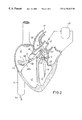
- FIG. 2 shows an embodiment of the intracardiac implementation of two intravascular pumps
- FIG. 3 is a schematic diagram for explaining a pump system
- FIG. 4 is a diagram for showing the dependance of the volume flow on the differential pressure between the intake side and the delivery side of a pump
- FIG. 5 shows a diagram of the variation in time of different pressures in the heart
- FIG. 1 shows an intravascular blood pump 10 , i.e. a blood pump that may be pushed through the blood vessel system of a patient to eventually arrive in the heart.
- the outer diameter of such a pump is nowhere larger than 7 mm.
- the pump 10 comprises a drive portion 11 and a rigidly connected pump portion 12 .
- the drive portion 11 has an elongated cylindrical housing 20 accommodating an electric motor 21 .
- the housing 20 is closed with an end wall 22 which is followed by a flexible catheter 14 sealing the same.
- the electric lines 23 for power supply and for controlling the electric motor 21 and further lines 23 a connected to the sensors of the pump 10 extend through this catheter 14 .
- the stator 24 of the motor has a plurality of circumferentially distributed coils and a magnetic yoke arranged in the longitudinal direction. It is firmly connected to the motor housing 20 .
- the stator 24 surrounds the rotor 26 that is connected with the motor shaft 25 and is made of permanent magnets magnetized in the effective/active direction.
- a bearing 27 supports the rear end of the motor shaft in the motor housing or the end wall 22 .
- the motor shaft extends throughout the entire length of the motor housing 20 and projects therefrom to the front.
- the front closure of the motor housing is formed by a tubular stationary hub member 30 having its rear end located in a reduced diameter projection 20 a of the housing 20 .
- the outer diameter of the hub member tapers towards the front end where a bearing 33 for supporting the motor shaft 25 is situated. This bearing is simultaneously designed as a shaft seal.
- the motor shaft 25 protrudes forward from the hub member 30 , where it carries an impeller wheel 34 with a hub 35 sitting on the shaft end and blades 36 or pump vanes protruding therefrom and being oblique with respect to the axis of the impeller wheel 34 .
- the impeller wheel 34 is accommodated in a cylindrical pump housing 32 connected with the motor housing 20 by three circumferentially distributed webs 38 .
- the motor housing 20 and the pump housing 32 are rigidly interconnected by means of a ring 38 and have equal outer diameters. The diameter of the pump 10 is nowhere larger than this outer diameter.
- the pump portion 12 for the opposite delivery direction, the blood being drawn along the motor housing and being discharged axially at the front end opening 27 .
- FIG. 2 illustrates an embodiment wherein two generally identical pumps 10 a, 10 b, configured as illustrated in FIG. 1, are used in a heart to support the heart or as a substitute for the pumping function of the heart when the heart is immobilized.
- Both pumps 10 a, 10 b are connected with a catheter 14 a, 14 b, respectively. They have been placed percutaneously, the catheter 14 a of the left cardiac pump 10 a extending through the aorta 40 and a hose 13 prolongating the pump 10 a being advanced into the left ventricle 42 through the aortic valve 41 .
- the pump portion 12 is prolongated by the flexible hose 13 connected with the pump housing 32 , the end and/or the side wall of the hose being provided with openings for blood to enter into the pump 10 a.
- the pump 10 a takes in through the hose 13 and delivers blood into the aorta 40 , while the aortic valve 41 abuts on the pump housing 32 or the hose 13 from outside.
- the pump 10 a is operated as a left heart pump with axial intake.
- the other pump 10 b is operated as a right heart pump in fluid communication with the right ventricle 43 .
- the catheter 14 b passes through the upper or the lower vena cava 44 into the right atrium 45 .
- the hose 13 of the pump 10 b projects through the tricuspidal valve 43 a and the pulmonary valve 46 into the pulmonary artery 47 from where the blood flows to the lung 48 for oxygenizing.
- the oxygenized blood the flows into the left vestibule 49 and on into the left ventricle 42 .
- the pump 10 b takes in through the radial inlet 50 and conveys blood through the hose 13 axially into the pulmonary artery 47 .
- the pump 10 b is operated inversely to the pump 10 a.
- Both pumps 10 a, 10 b are introduced into the heart without one of the ventricles having to be surgically opened.
- FIG. 3 is a schematic illustration of the two pumps 10 a, 10 b with different sensors.
- the outer surface of the drive unit 11 is provided with a first pressure sensor 60 located close to the radial opening 51 , whereas a second pressure sensor 61 is arranged near the inlet of the pump housing.
- the lines 23 a of the sensors are integrated into the elements of the pump and extend through the catheter 14 together with the supply lines 23 .
- the sensor surface of the pressure sensor 60 is on the exterior of the motor housing.
- the sensor face of the pressure sensor 61 is provided on the inner surface of the hose 13 .
- a temperature sensor may be provided at the drive portion for monitoring the motor temperature.
- the supply lines 23 and the lines 23 a are connected with an extracorporeal interface 65 ,.
- This interface supplies the signals from the sensors to a control unit 66 that evaluates these signals and controls the pumps 1 a, 10 b in dependence thereon.
- a keypad and display device 67 is connected with the control unit 66 to allow for information to be entered and displayed.
- a differential pressure will appear at the pressure sensors due to the different pressure conditions.
- this differential pressure also varies in time.
- equal measured pressure values indicate an incorrect positioning of the pump because both pressure sensors measure the same pressure.
- the evaluation of the data supplied by the two pressure sensors with consideration to the motor current, provides important information on the positioning and the operation of the pump. By comparing the differential pressure to the momentaneous motor current, it is also possible to determine blocking conditions or cavitation.
- the operation of the pump can be maintained with acceptable total hemolysis rates for the required period of use and with the required volume flow of 3.6 to 5 l/min.
- the performance trends of various parameters may be displayed and analyzed for several hours of operation, with alarm conditions that require immediate intervention being detected without necessitating permanent control by personnel.
- the heart of a patient can be monitored without removing the pump.
- the control unit 66 controls both pumps 10 a, 10 b such that each pump delivers a certain volume flow (volume of blood per unit time). In doing so, the right heart pump 10 b pumps a predetermined percentage of the volume flow of the left heart pump 10 a, for example 90%. The volume flow of the right heart pump is always smaller than that of the left heart pump. Primarily, the pumping capacity of the left heart pump 10 a is controlled such that a predetermined volume flow is maintained. Subsequently, the pumping capacity of the right heart pump 10 b is determined as a function thereof. This is a master-slave operation, where usually the left heart pump 10 a is the master and the right heart pump 10 b is the slave.
- the pumps are driven by synchronous motors, with the control unit 66 supplying the required drive frequency or rotational speed n.
- the volume flow of each pump is a function of the rotational speed n.
- FIG. 4 illustrates the volume flow V of a pump in dependance on the differential pressure ⁇ P between the intake side and the delivery side of the pump for respective different rotational speeds n.
- Each parallel straight line relates to a specific rotational speed n. It is evident that the volume flow V may be calculated from the differential pressure ⁇ P when the rotational speed n is known.
- the motor 21 is an electronically commutated synchronous motor. Since the rotational speed is preset by the control unit, the rotational speed is known.
- the differential pressure ⁇ P is determined by means of the sensors 60 and 61 or 62 and 63 , respectively. Moreover, of course, the absolute values of the pressures are measured and evaluated as well.
- the pressure sensors supply abnormal values.
- the rotational speed of the respective pump will then be reduced for a ceratin time so that the cardiac tissue may disengage itself, and, subsequently, the rotational speed will be increased again to the desired number.
- the control unit 66 will effect a limitation—and, if need be, a reduction—of the volume flow to avoid damage to downstream organs (lungs).
- Measuring the pressure also provides a watch function.
- the pressure in the right ventricle or in the pulmonary artery must not exceed a certain value, and the pressure in the left ventricle or in the aorta must not fall below a certain pressure.
- an alarm is emitted or an adjustment is effected.
- FIG. 5 illustrates the pressure variation p 1 in the left ventricle of the beating heart with the systoles S and the diastoles D.
- p 1 the pressure variation p 1 in the left ventricle of the beating heart with the systoles S and the diastoles D.
- the differential pressure ⁇ P is determined from p ⁇ p 1 . This differential pressure may be determined with the pressure sensors provided on the pumps.
- measuring the pressure is not necessary for positioning. Rather, the positioning may also be monitored by means of the current variation of the pump. As long as the inlet and the outlet of a pump are in the same space, both are subjected to the same pressure. If the pump is driven with a certain rotational speed, the variation in time of the pump current is constant. If, however, the outlet and the inlet of the pump are in different spaces with pressures varying in time, no smooth, but a pulsating pump current will be obtained. Thus, it can be determined on the basis of the pump current, whether the cardiac valve correctly encloses the pump housing or the hose so that the inlet of the pump is located in the ventricle or the vestibule and the outlet is in the aorta or the pulmonary artery.
- determining the position of the blood pump in the heart does not require a pressure measuring device at all. All that is needed is a measuring device that supplies an information signal corresponding to the differential pressure between the outlet side and the inlet side of the pump.
- This measuring device may be a device measuring the motor current of the motor driving the pump.
- the diagram of FIG. 7, similar to that of FIG. 4, illustrates the volume flow V of a pump as a function of the current I of the motor driving this pump for different rotational speeds n, respectively.
- Each of the parallel straight lines relates to a certain rotational speed n. It is evident that the volume flow V may be determined from the amount of the current I, when the rotational speed n is known. Thus, the volume flow V may be determined by simply measuring the current.
- the correct position of the pump in the heart can also be verified by measuring the current.
- the pulsating pressure designated P 1 in FIG. 5 is caused in the ventricle 42 at the inlet of the blood pump.
- the less pulsating pressure P 2 of FIG. 5 is generated at the pump outlet.
- the differential pressure ⁇ P is a pulsating value. If, on the other hand, the blood pump is entirely located in the aorta, the pressure difference between the inlet and the outlet of the pump is substantially zero. The same is true when the blood pump is entirely located in the left ventricle 42 .
- the correct position of the pump may be determined.
- the invention allows to control the pump operation so as to obtain a desired volume flow as a function of the result of a pressure measurement or the result of a current measurement. These measurements may be taken in a very simple manner without voluminous measuring devices so that the operation of the pump may be accurately monitored, despite the compact structure.
Abstract
Description
Claims (13)
Applications Claiming Priority (1)
| Application Number | Priority Date | Filing Date | Title |
|---|---|---|---|
| PCT/EP1998/001866 WO1998043688A1 (en) | 1997-04-02 | 1998-03-31 | Intracardiac blood pump |
Publications (1)
| Publication Number | Publication Date |
|---|---|
| US6176822B1 true US6176822B1 (en) | 2001-01-23 |
Family
ID=8166928
Family Applications (1)
| Application Number | Title | Priority Date | Filing Date |
|---|---|---|---|
| US09/194,521 Expired - Lifetime US6176822B1 (en) | 1998-03-31 | 1998-03-31 | Intracardiac blood pump |
Country Status (1)
| Country | Link |
|---|---|
| US (1) | US6176822B1 (en) |
Cited By (132)
| Publication number | Priority date | Publication date | Assignee | Title |
|---|---|---|---|---|
| US20020042596A1 (en) * | 1999-04-30 | 2002-04-11 | Hartlaub Jerome T. | Method and apparatus to sense temperature in an implantable pump |
| US20020052656A1 (en) * | 2000-02-04 | 2002-05-02 | Michelson Gary Karlin | Expandable push-in interbody spinal fusion implant |
| US20020173695A1 (en) * | 2001-05-16 | 2002-11-21 | Mikhail Skliar | Physiologically-based control system and method for using the same |
| US6500205B1 (en) | 2000-04-19 | 2002-12-31 | Gary K. Michelson | Expandable threaded arcuate interbody spinal fusion implant with cylindrical configuration during insertion |
| US6527698B1 (en) | 2000-05-30 | 2003-03-04 | Abiomed, Inc. | Active left-right flow control in a two chamber cardiac prosthesis |
| US20030050701A1 (en) * | 2000-02-04 | 2003-03-13 | Michelson Gary Karlin | Expandable push-in arcuate interbody spinal fusion implant with cylindrical configuration during insertion |
| US6540658B1 (en) | 2000-05-30 | 2003-04-01 | Abiomed, Inc. | Left-right flow control algorithm in a two chamber cardiac prosthesis |
| US6623420B2 (en) * | 2001-08-16 | 2003-09-23 | Apex Medical, Inc. | Physiological heart pump control |
| US20030187322A1 (en) * | 2000-08-18 | 2003-10-02 | Thorsten Siess | Intracardiac blood pump |
| US20040059420A1 (en) * | 2000-02-04 | 2004-03-25 | Michelson Gary Karlin | Expandable push-in arcuate interbody spinal fusion implant with tapered configuration during insertion |
| US20040133061A1 (en) * | 2002-09-10 | 2004-07-08 | Miwatec Incorporated | Methods for detecting an abnormal condition of a blood pump system |
| US20050060037A1 (en) * | 2000-07-07 | 2005-03-17 | Michelson Gary Karlin | Expandable implant with interlocking walls and method for use thereof |
| US20050107657A1 (en) * | 2002-03-08 | 2005-05-19 | Michel Carrier | Dual inlet mixed-flow blood pump |
| US20050274558A1 (en) * | 2004-05-07 | 2005-12-15 | Kabushiiki Kaisha Moric | Electric vehicle |
| US20060122456A1 (en) * | 2004-12-03 | 2006-06-08 | Larose Jeffrey A | Wide blade, axial flow pump |
| US20060161095A1 (en) * | 1999-09-03 | 2006-07-20 | A-Med Systems, Inc. | Guidable intravascular blood pump and related methods |
| US20060245959A1 (en) * | 2005-04-29 | 2006-11-02 | Larose Jeffrey A | Multiple rotor, wide blade, axial flow pump |
| WO2006133209A1 (en) | 2005-06-06 | 2006-12-14 | The Cleveland Clinic Foundation | Blood pump |
| US20070078293A1 (en) * | 2005-10-05 | 2007-04-05 | Shambaugh Charles R Jr | Impeller for a rotary ventricular assist device |
| US20070231135A1 (en) * | 2006-03-31 | 2007-10-04 | Orqis Medical Corporation | Rotary Blood Pump |
| US20070280841A1 (en) * | 2006-01-13 | 2007-12-06 | Larose Jeffrey A | Hydrodynamic thrust bearings for rotary blood pumps |
| US20080089797A1 (en) * | 2003-09-18 | 2008-04-17 | Wampler Richard K | Rotary Blood Pump |
| US20080114339A1 (en) * | 2006-03-23 | 2008-05-15 | The Penn State Research Foundation | Heart assist device with expandable impeller pump |
| US20080132747A1 (en) * | 2006-12-01 | 2008-06-05 | Medical Value Partners, Llc | Medical Device |
| US20080306327A1 (en) * | 2007-06-05 | 2008-12-11 | Medical Value Partners, Llc | Apparatus Comprising a Drive Cable for a Medical Device |
| US20090062597A1 (en) * | 2007-08-29 | 2009-03-05 | Medical Value Partners, Llc | Article Comprising an Impeller |
| US20090203957A1 (en) * | 2008-02-08 | 2009-08-13 | Larose Jeffrey A | Ventricular assist device for intraventricular placement |
| US20100016960A1 (en) * | 1997-10-09 | 2010-01-21 | Bolling Steven F | Implantable Heart Assist System And Method Of Applying Same |
| US20100174131A1 (en) * | 2007-06-14 | 2010-07-08 | Calon Cardio Technology Limited | Reduced Diameter Axial Rotary Pump for Cardiac Assist |
| US20100222878A1 (en) * | 2009-02-27 | 2010-09-02 | Thoratec Corporation | Blood pump system with arterial pressure monitoring |
| US20100222634A1 (en) * | 2009-02-27 | 2010-09-02 | Thoratec Corporation | Blood flow meter |
| WO2010099411A1 (en) * | 2009-02-27 | 2010-09-02 | Thoratec Corporation | Prevention of aortic valve fusion |
| US20100222633A1 (en) * | 2009-02-27 | 2010-09-02 | Victor Poirier | Blood pump system with controlled weaning |
| WO2010099285A1 (en) * | 2009-02-27 | 2010-09-02 | Thoratec Corporation | Maximizing blood pump flow while avoiding left ventricle collapse |
| US20110004046A1 (en) * | 2009-07-01 | 2011-01-06 | The Penn State Research Foundation | Blood pump with expandable cannula |
| US7927068B2 (en) | 2004-09-17 | 2011-04-19 | Thoratec Corporation | Expandable impeller pump |
| US8449443B2 (en) | 2008-10-06 | 2013-05-28 | Indiana University Research And Technology Corporation | Active or passive assistance in the circulatory system |
| US8485961B2 (en) | 2011-01-05 | 2013-07-16 | Thoratec Corporation | Impeller housing for percutaneous heart pump |
| WO2013160407A1 (en) * | 2012-04-27 | 2013-10-31 | Abiomed Europe Gmbh | Intravascular rotary blood pump |
| US8591393B2 (en) | 2011-01-06 | 2013-11-26 | Thoratec Corporation | Catheter pump |
| US8597170B2 (en) | 2011-01-05 | 2013-12-03 | Thoratec Corporation | Catheter pump |
| US20140073838A1 (en) * | 2009-12-30 | 2014-03-13 | Thoratec Corporation | Mobility-Enhancing Blood Pump System |
| US8672611B2 (en) | 2006-01-13 | 2014-03-18 | Heartware, Inc. | Stabilizing drive for contactless rotary blood pump impeller |
| US8690749B1 (en) | 2009-11-02 | 2014-04-08 | Anthony Nunez | Wireless compressible heart pump |
| US8721517B2 (en) | 2012-05-14 | 2014-05-13 | Thoratec Corporation | Impeller for catheter pump |
| US8821365B2 (en) | 2009-07-29 | 2014-09-02 | Thoratec Corporation | Rotation drive device and centrifugal pump apparatus using the same |
| US8827661B2 (en) | 2008-06-23 | 2014-09-09 | Thoratec Corporation | Blood pump apparatus |
| US20140303426A1 (en) * | 2013-04-05 | 2014-10-09 | Circulite, Inc. | Implantable blood pump, blood pump system, and method for data transfer in a blood pump system |
| US8905910B2 (en) | 2010-06-22 | 2014-12-09 | Thoratec Corporation | Fluid delivery system and method for monitoring fluid delivery system |
| US9068572B2 (en) | 2010-07-12 | 2015-06-30 | Thoratec Corporation | Centrifugal pump apparatus |
| US9067005B2 (en) | 2008-12-08 | 2015-06-30 | Thoratec Corporation | Centrifugal pump apparatus |
| US9089635B2 (en) | 2010-06-22 | 2015-07-28 | Thoratec Corporation | Apparatus and method for modifying pressure-flow characteristics of a pump |
| EP2109472B1 (en) | 2007-02-09 | 2015-08-19 | KCI Licensing, Inc. | System for managing reduced pressure at a tissue site |
| US9132215B2 (en) | 2010-02-16 | 2015-09-15 | Thoratee Corporation | Centrifugal pump apparatus |
| US9133854B2 (en) | 2010-03-26 | 2015-09-15 | Thoratec Corporation | Centrifugal blood pump device |
| US9138518B2 (en) | 2011-01-06 | 2015-09-22 | Thoratec Corporation | Percutaneous heart pump |
| WO2015160943A1 (en) | 2014-04-15 | 2015-10-22 | Thoratec Corporation | Sensors for catheter pumps |
| US9308302B2 (en) | 2013-03-15 | 2016-04-12 | Thoratec Corporation | Catheter pump assembly including a stator |
| US9327067B2 (en) | 2012-05-14 | 2016-05-03 | Thoratec Corporation | Impeller for catheter pump |
| US9339597B2 (en) | 2012-02-07 | 2016-05-17 | Hridaya Inc. | Hemodynamic assist device |
| US9358329B2 (en) | 2012-07-03 | 2016-06-07 | Thoratec Corporation | Catheter pump |
| US9366261B2 (en) | 2012-01-18 | 2016-06-14 | Thoratec Corporation | Centrifugal pump device |
| US9371826B2 (en) | 2013-01-24 | 2016-06-21 | Thoratec Corporation | Impeller position compensation using field oriented control |
| US9381285B2 (en) | 2009-03-05 | 2016-07-05 | Thoratec Corporation | Centrifugal pump apparatus |
| US9381288B2 (en) | 2013-03-13 | 2016-07-05 | Thoratec Corporation | Fluid handling system |
| US9382908B2 (en) | 2010-09-14 | 2016-07-05 | Thoratec Corporation | Centrifugal pump apparatus |
| US9410549B2 (en) | 2009-03-06 | 2016-08-09 | Thoratec Corporation | Centrifugal pump apparatus |
| US9421311B2 (en) | 2012-07-03 | 2016-08-23 | Thoratec Corporation | Motor assembly for catheter pump |
| US9433717B2 (en) | 2010-09-24 | 2016-09-06 | Thoratec Corporation | Generating artificial pulse |
| US9446179B2 (en) | 2012-05-14 | 2016-09-20 | Thoratec Corporation | Distal bearing support |
| US9474840B2 (en) | 2012-04-27 | 2016-10-25 | Abiomed Europe Gmbh | Intravascular rotary blood pump |
| WO2017015210A1 (en) * | 2015-07-20 | 2017-01-26 | Thoratec Corporation | Strain gauge for flow estimation |
| US9556873B2 (en) | 2013-02-27 | 2017-01-31 | Tc1 Llc | Startup sequence for centrifugal pump with levitated impeller |
| US9572915B2 (en) | 2012-03-26 | 2017-02-21 | Procyrion, Inc. | Systems and methods for fluid flows and/or pressures for circulation and perfusion enhancement |
| US20170049945A1 (en) * | 2013-06-27 | 2017-02-23 | Oslo Universitetssykehus Hf | Monitoring of a cardiac assist device |
| US9623161B2 (en) | 2014-08-26 | 2017-04-18 | Tc1 Llc | Blood pump and method of suction detection |
| US9675738B2 (en) | 2015-01-22 | 2017-06-13 | Tc1 Llc | Attachment mechanisms for motor of catheter pump |
| US9675739B2 (en) | 2015-01-22 | 2017-06-13 | Tc1 Llc | Motor assembly with heat exchanger for catheter pump |
| US9694123B2 (en) | 2014-04-15 | 2017-07-04 | Tc1 Llc | Methods and systems for controlling a blood pump |
| US9713663B2 (en) | 2013-04-30 | 2017-07-25 | Tc1 Llc | Cardiac pump with speed adapted for ventricle unloading |
| US9757502B2 (en) | 2010-09-24 | 2017-09-12 | Tci Llc | Control of circulatory assist systems |
| US9770543B2 (en) | 2015-01-22 | 2017-09-26 | Tc1 Llc | Reduced rotational mass motor assembly for catheter pump |
| US9775936B2 (en) | 2010-10-18 | 2017-10-03 | WorldHeart Corp. | Blood pump with separate mixed-flow and axial-flow impeller stages, components therefor and related methods |
| US9827356B2 (en) | 2014-04-15 | 2017-11-28 | Tc1 Llc | Catheter pump with access ports |
| US9850906B2 (en) | 2011-03-28 | 2017-12-26 | Tc1 Llc | Rotation drive device and centrifugal pump apparatus employing same |
| US9872947B2 (en) | 2012-05-14 | 2018-01-23 | Tc1 Llc | Sheath system for catheter pump |
| WO2018017563A1 (en) * | 2016-07-19 | 2018-01-25 | Heartware, Inc. | Ventricular assist devices and integrated sensors thereof |
| US9901666B2 (en) | 2015-07-20 | 2018-02-27 | Tc1 Llc | Flow estimation using hall-effect sensors for measuring impeller eccentricity |
| US9907890B2 (en) | 2015-04-16 | 2018-03-06 | Tc1 Llc | Catheter pump with positioning brace |
| WO2018053504A1 (en) | 2016-09-19 | 2018-03-22 | Abiomed, Inc. | Cardiovascular assist system that quantifies heart function and facilitates heart recovery |
| US9968720B2 (en) | 2016-04-11 | 2018-05-15 | CorWave SA | Implantable pump system having an undulating membrane |
| WO2018088939A1 (en) | 2016-11-09 | 2018-05-17 | Алексей Васильевич КОРОТЕЕВ | Microaxial pump for assisting blood circulation (variants) |
| US10052420B2 (en) | 2013-04-30 | 2018-08-21 | Tc1 Llc | Heart beat identification and pump speed synchronization |
| US20180280601A1 (en) * | 2017-03-29 | 2018-10-04 | Tc1 Llc | Pressure sensing ventricular assist devices and methods of use |
| US10105475B2 (en) | 2014-04-15 | 2018-10-23 | Tc1 Llc | Catheter pump introducer systems and methods |
| US10111994B2 (en) | 2013-05-14 | 2018-10-30 | Heartware, Inc. | Blood pump with separate mixed-flow and axial-flow impeller stages and multi-stage stators |
| US10117983B2 (en) | 2015-11-16 | 2018-11-06 | Tc1 Llc | Pressure/flow characteristic modification of a centrifugal pump in a ventricular assist device |
| US10166318B2 (en) | 2015-02-12 | 2019-01-01 | Tc1 Llc | System and method for controlling the position of a levitated rotor |
| US10166319B2 (en) | 2016-04-11 | 2019-01-01 | CorWave SA | Implantable pump system having a coaxial ventricular cannula |
| US10188779B1 (en) | 2017-11-29 | 2019-01-29 | CorWave SA | Implantable pump system having an undulating membrane with improved hydraulic performance |
| US10245361B2 (en) | 2015-02-13 | 2019-04-02 | Tc1 Llc | Impeller suspension mechanism for heart pump |
| US10293090B2 (en) | 2014-04-25 | 2019-05-21 | Yale University | Percutaneous device and method for promoting movement of a bodily fluid |
| US10342906B2 (en) | 2016-06-06 | 2019-07-09 | Abiomed, Inc. | Blood pump assembly having a sensor and a sensor shield |
| US10371152B2 (en) | 2015-02-12 | 2019-08-06 | Tc1 Llc | Alternating pump gaps |
| WO2019173596A1 (en) * | 2018-03-09 | 2019-09-12 | Boston Scientific Scimed, Inc. | Magnetic coupler for hemostatic rotor sealing |
| WO2019178512A1 (en) * | 2018-03-16 | 2019-09-19 | Abiomed, Inc. | Systems and methods for estimating a position of a heart pump |
| US10449279B2 (en) | 2014-08-18 | 2019-10-22 | Tc1 Llc | Guide features for percutaneous catheter pump |
| WO2019234153A1 (en) * | 2018-06-06 | 2019-12-12 | Kardion Gmbh | Implantable vascular support system |
| US10506935B2 (en) | 2015-02-11 | 2019-12-17 | Tc1 Llc | Heart beat identification and pump speed synchronization |
| US10525178B2 (en) | 2013-03-15 | 2020-01-07 | Tc1 Llc | Catheter pump assembly including a stator |
| WO2020028320A1 (en) | 2018-07-30 | 2020-02-06 | Cardiovascular Systems, Inc. | Intravascular pump with proximal and distal pressure or flow sensors and distal sensor tracking |
| US10583232B2 (en) | 2014-04-15 | 2020-03-10 | Tc1 Llc | Catheter pump with off-set motor position |
| US10765791B2 (en) | 2017-06-09 | 2020-09-08 | Abiomed, Inc. | Determination of cardiac parameters for modulation of blood pump support |
| US10799625B2 (en) | 2019-03-15 | 2020-10-13 | CorWave SA | Systems and methods for controlling an implantable blood pump |
| US10933181B2 (en) | 2017-03-31 | 2021-03-02 | CorWave SA | Implantable pump system having a rectangular membrane |
| US10960118B2 (en) | 2018-07-31 | 2021-03-30 | Abiomed, Inc. | Systems and methods for controlling a heart pump to minimize myocardial oxygen consumption |
| US11033728B2 (en) | 2013-03-13 | 2021-06-15 | Tc1 Llc | Fluid handling system |
| US11077294B2 (en) | 2013-03-13 | 2021-08-03 | Tc1 Llc | Sheath assembly for catheter pump |
| US11154700B2 (en) | 2014-02-25 | 2021-10-26 | MI-VAD, Inc. | Ventricular assist device and method |
| US11160970B2 (en) | 2016-07-21 | 2021-11-02 | Tc1 Llc | Fluid seals for catheter pump motor assembly |
| US11191946B2 (en) | 2020-03-06 | 2021-12-07 | CorWave SA | Implantable blood pumps comprising a linear bearing |
| CN113769260A (en) * | 2021-09-16 | 2021-12-10 | 苏州心岭迈德医疗科技有限公司 | Catheter pump, auxiliary blood pumping system and control method and device of catheter pump |
| US11219756B2 (en) | 2012-07-03 | 2022-01-11 | Tc1 Llc | Motor assembly for catheter pump |
| US11229786B2 (en) | 2012-05-14 | 2022-01-25 | Tc1 Llc | Impeller for catheter pump |
| US11389638B2 (en) * | 2012-02-07 | 2022-07-19 | Hridaya, Inc. | Hemodynamic assist device |
| US11458295B2 (en) | 2011-11-28 | 2022-10-04 | MI-VAD, Inc. | Ventricular assist device and method |
| US11478629B2 (en) | 2017-03-29 | 2022-10-25 | Tc1 Llc | Adjusting pump protocol based on irregular heart rhythm |
| US11491322B2 (en) | 2016-07-21 | 2022-11-08 | Tc1 Llc | Gas-filled chamber for catheter pump motor assembly |
| US11512689B2 (en) | 2017-11-10 | 2022-11-29 | CorWave SA | Undulating-membrane fluid circulator |
| US11574741B2 (en) | 2018-06-19 | 2023-02-07 | Abiomed, Inc. | Systems and methods for determining cardiac output |
| US11684769B2 (en) * | 2018-12-21 | 2023-06-27 | Tc1 Llc | Implantable blood pump assembly including pressure sensor and methods of assembling same |
| WO2023215500A1 (en) * | 2022-05-05 | 2023-11-09 | Abiomed, Inc. | Position detection for a circulatory support device |
Citations (27)
| Publication number | Priority date | Publication date | Assignee | Title |
|---|---|---|---|---|
| US3568659A (en) | 1968-09-24 | 1971-03-09 | James N Karnegis | Disposable percutaneous intracardiac pump and method of pumping blood |
| US3995617A (en) | 1972-05-31 | 1976-12-07 | Watkins David H | Heart assist method and catheter |
| US4382199A (en) | 1980-11-06 | 1983-05-03 | Nu-Tech Industries, Inc. | Hydrodynamic bearing system for a brushless DC motor |
| US4512726A (en) * | 1982-02-09 | 1985-04-23 | Strimling Walter E | Pump adaptable for use as an artificial heart |
| US4688998A (en) | 1981-03-18 | 1987-08-25 | Olsen Don B | Magnetically suspended and rotated impellor pump apparatus and method |
| US4704121A (en) | 1983-09-28 | 1987-11-03 | Nimbus, Inc. | Anti-thrombogenic blood pump |
| US4779614A (en) | 1987-04-09 | 1988-10-25 | Nimbus Medical, Inc. | Magnetically suspended rotor axial flow blood pump |
| US4817586A (en) | 1987-11-24 | 1989-04-04 | Nimbus Medical, Inc. | Percutaneous bloom pump with mixed-flow output |
| US4846152A (en) | 1987-11-24 | 1989-07-11 | Nimbus Medical, Inc. | Single-stage axial flow blood pump |
| US4895557A (en) | 1987-12-07 | 1990-01-23 | Nimbus Medical, Inc. | Drive mechanism for powering intravascular blood pumps |
| US4906229A (en) | 1988-05-03 | 1990-03-06 | Nimbus Medical, Inc. | High-frequency transvalvular axisymmetric blood pump |
| US4908012A (en) | 1988-08-08 | 1990-03-13 | Nimbus Medical, Inc. | Chronic ventricular assist system |
| US4919647A (en) | 1988-10-13 | 1990-04-24 | Kensey Nash Corporation | Aortically located blood pumping catheter and method of use |
| US4944722A (en) | 1989-02-23 | 1990-07-31 | Nimbus Medical, Inc. | Percutaneous axial flow blood pump |
| EP0445782A1 (en) | 1990-03-08 | 1991-09-11 | Sun Medical Technology Research Corporation | Auxiliary artificial heart of the embedded-in-body type |
| US5061256A (en) | 1987-12-07 | 1991-10-29 | Johnson & Johnson | Inflow cannula for intravascular blood pumps |
| US5092879A (en) | 1988-02-17 | 1992-03-03 | Jarvik Robert K | Intraventricular artificial hearts and methods of their surgical implantation and use |
| US5112292A (en) | 1989-01-09 | 1992-05-12 | American Biomed, Inc. | Helifoil pump |
| US5376114A (en) | 1992-10-30 | 1994-12-27 | Jarvik; Robert | Cannula pumps for temporary cardiac support and methods of their application and use |
| US5385454A (en) | 1992-04-14 | 1995-01-31 | Ebara Corporation | Bearing device for use in a canned motor |
| US5385581A (en) | 1982-04-04 | 1995-01-31 | Life Extenders Corporation | Magnetically suspended and rotated rotor |
| US5393207A (en) | 1993-01-21 | 1995-02-28 | Nimbus, Inc. | Blood pump with disposable rotor assembly |
| US5507629A (en) | 1994-06-17 | 1996-04-16 | Jarvik; Robert | Artificial hearts with permanent magnet bearings |
| US5527159A (en) | 1993-11-10 | 1996-06-18 | The United States Of America As Represented By The Administrator Of The National Aeronautics And Space Administration | Rotary blood pump |
| US5695471A (en) | 1996-02-20 | 1997-12-09 | Kriton Medical, Inc. | Sealless rotary blood pump with passive magnetic radial bearings and blood immersed axial bearings |
| US5911685A (en) | 1996-04-03 | 1999-06-15 | Guidant Corporation | Method and apparatus for cardiac blood flow assistance |
| US5964694A (en) | 1997-04-02 | 1999-10-12 | Guidant Corporation | Method and apparatus for cardiac blood flow assistance |
-
1998
- 1998-03-31 US US09/194,521 patent/US6176822B1/en not_active Expired - Lifetime
Patent Citations (28)
| Publication number | Priority date | Publication date | Assignee | Title |
|---|---|---|---|---|
| US3568659A (en) | 1968-09-24 | 1971-03-09 | James N Karnegis | Disposable percutaneous intracardiac pump and method of pumping blood |
| US3995617A (en) | 1972-05-31 | 1976-12-07 | Watkins David H | Heart assist method and catheter |
| US4382199A (en) | 1980-11-06 | 1983-05-03 | Nu-Tech Industries, Inc. | Hydrodynamic bearing system for a brushless DC motor |
| US4688998A (en) | 1981-03-18 | 1987-08-25 | Olsen Don B | Magnetically suspended and rotated impellor pump apparatus and method |
| US4512726A (en) * | 1982-02-09 | 1985-04-23 | Strimling Walter E | Pump adaptable for use as an artificial heart |
| US5385581A (en) | 1982-04-04 | 1995-01-31 | Life Extenders Corporation | Magnetically suspended and rotated rotor |
| US4704121A (en) | 1983-09-28 | 1987-11-03 | Nimbus, Inc. | Anti-thrombogenic blood pump |
| US4779614A (en) | 1987-04-09 | 1988-10-25 | Nimbus Medical, Inc. | Magnetically suspended rotor axial flow blood pump |
| US4846152A (en) | 1987-11-24 | 1989-07-11 | Nimbus Medical, Inc. | Single-stage axial flow blood pump |
| US4817586A (en) | 1987-11-24 | 1989-04-04 | Nimbus Medical, Inc. | Percutaneous bloom pump with mixed-flow output |
| US4895557A (en) | 1987-12-07 | 1990-01-23 | Nimbus Medical, Inc. | Drive mechanism for powering intravascular blood pumps |
| US5061256A (en) | 1987-12-07 | 1991-10-29 | Johnson & Johnson | Inflow cannula for intravascular blood pumps |
| US5092879A (en) | 1988-02-17 | 1992-03-03 | Jarvik Robert K | Intraventricular artificial hearts and methods of their surgical implantation and use |
| US4906229A (en) | 1988-05-03 | 1990-03-06 | Nimbus Medical, Inc. | High-frequency transvalvular axisymmetric blood pump |
| US4908012A (en) | 1988-08-08 | 1990-03-13 | Nimbus Medical, Inc. | Chronic ventricular assist system |
| US4919647A (en) | 1988-10-13 | 1990-04-24 | Kensey Nash Corporation | Aortically located blood pumping catheter and method of use |
| US5112292A (en) | 1989-01-09 | 1992-05-12 | American Biomed, Inc. | Helifoil pump |
| US4944722A (en) | 1989-02-23 | 1990-07-31 | Nimbus Medical, Inc. | Percutaneous axial flow blood pump |
| EP0445782A1 (en) | 1990-03-08 | 1991-09-11 | Sun Medical Technology Research Corporation | Auxiliary artificial heart of the embedded-in-body type |
| US5385454A (en) | 1992-04-14 | 1995-01-31 | Ebara Corporation | Bearing device for use in a canned motor |
| US5376114A (en) | 1992-10-30 | 1994-12-27 | Jarvik; Robert | Cannula pumps for temporary cardiac support and methods of their application and use |
| US5393207A (en) | 1993-01-21 | 1995-02-28 | Nimbus, Inc. | Blood pump with disposable rotor assembly |
| US5527159A (en) | 1993-11-10 | 1996-06-18 | The United States Of America As Represented By The Administrator Of The National Aeronautics And Space Administration | Rotary blood pump |
| US5507629A (en) | 1994-06-17 | 1996-04-16 | Jarvik; Robert | Artificial hearts with permanent magnet bearings |
| US5695471A (en) | 1996-02-20 | 1997-12-09 | Kriton Medical, Inc. | Sealless rotary blood pump with passive magnetic radial bearings and blood immersed axial bearings |
| US5911685A (en) | 1996-04-03 | 1999-06-15 | Guidant Corporation | Method and apparatus for cardiac blood flow assistance |
| US5921913A (en) | 1996-04-03 | 1999-07-13 | Guidant Corporation | Statorless intravascular microaxial flow pump |
| US5964694A (en) | 1997-04-02 | 1999-10-12 | Guidant Corporation | Method and apparatus for cardiac blood flow assistance |
Non-Patent Citations (2)
| Title |
|---|
| Article: Control of Rotary Pulsatile Cardiac Assist Pump Driven by an Electric Motor; Publication date Oct. 29, 1992. |
| Article: Development of a Miniature Intraventricular Axial Flow Blood Pump, Publication date Jul./Sep. 1993 issue of ASAIO Journal. |
Cited By (343)
| Publication number | Priority date | Publication date | Assignee | Title |
|---|---|---|---|---|
| US8900115B2 (en) | 1997-10-09 | 2014-12-02 | Thoratec Corporation | Implantable heart assist system and method of applying same |
| US7993260B2 (en) | 1997-10-09 | 2011-08-09 | Thoratec Corporation | Implantable heart assist system and method of applying same |
| US7998054B2 (en) | 1997-10-09 | 2011-08-16 | Thoratec Corporation | Implantable heart assist system and method of applying same |
| US20100016960A1 (en) * | 1997-10-09 | 2010-01-21 | Bolling Steven F | Implantable Heart Assist System And Method Of Applying Same |
| US20020042596A1 (en) * | 1999-04-30 | 2002-04-11 | Hartlaub Jerome T. | Method and apparatus to sense temperature in an implantable pump |
| US20100145271A1 (en) * | 1999-04-30 | 2010-06-10 | Medtronic, Inc. | Method to sense temperature in an implantable pump |
| US7658737B2 (en) * | 1999-04-30 | 2010-02-09 | Medtronic, Inc. | Method and apparatus to sense temperature in an implantable pump |
| US20080063539A1 (en) * | 1999-04-30 | 2008-03-13 | Medtronic, Inc. | Method To Sense Temperature In An Implantable Pump |
| US10279095B2 (en) | 1999-09-03 | 2019-05-07 | Maquet Cardiovascular Llc | Guidable intravascular blood pump and related methods |
| US20100210895A1 (en) * | 1999-09-03 | 2010-08-19 | Aboul-Hosn Walid N | Guidable Intravascular Blood Pump and Related Methods |
| US10300186B2 (en) | 1999-09-03 | 2019-05-28 | Maquet Cardiovascular Llc | Guidable intravascular blood pump and related methods |
| US10300185B2 (en) | 1999-09-03 | 2019-05-28 | Maquet Cardiovascular Llc | Guidable intravascular blood pump and related methods |
| US9545468B2 (en) | 1999-09-03 | 2017-01-17 | Maquet Cardiovascular Llc | Guidable intravascular blood pump and related methods |
| US9561314B2 (en) | 1999-09-03 | 2017-02-07 | Maquet Cardiovascular Llc | Guidable intravascular blood pump and related methods |
| US10322218B2 (en) | 1999-09-03 | 2019-06-18 | Maquet Cardiovascular Llc | Guidable intravascular blood pump and related methods |
| US10328191B2 (en) | 1999-09-03 | 2019-06-25 | Maquet Cardiovascular Llc | Guidable intravascular blood pump and related methods |
| US10238783B2 (en) | 1999-09-03 | 2019-03-26 | Maquet Cardiovascular Llc | Guidable intravascular blood pump and related methods |
| US9597437B2 (en) | 1999-09-03 | 2017-03-21 | Maquet Cardiovascular Llc | Guidable intravascular blood pump and related methods |
| US10357598B2 (en) | 1999-09-03 | 2019-07-23 | Maquet Cardiovascular Llc | Guidable intravascular blood pump and related methods |
| US9327068B2 (en) | 1999-09-03 | 2016-05-03 | Maquet Cardiovascular Llc | Guidable intravascular blood pump and related methods |
| US7731675B2 (en) * | 1999-09-03 | 2010-06-08 | Maquet Cardiovascular Llc | Guidable intravascular blood pump and related methods |
| US8888728B2 (en) | 1999-09-03 | 2014-11-18 | Maquet Cardiovascular Llc | Guidable intravascular blood pump and related methods |
| US20060161095A1 (en) * | 1999-09-03 | 2006-07-20 | A-Med Systems, Inc. | Guidable intravascular blood pump and related methods |
| US9789238B2 (en) | 1999-09-03 | 2017-10-17 | Maquet Cardiovascular, Llc | Guidable intravascular blood pump and related methods |
| US20050065608A1 (en) * | 2000-02-04 | 2005-03-24 | Michelson Gary K. | Expandable threaded arcuate interbody spinal fusion implant with lordotic configuration during insertion |
| US20020052656A1 (en) * | 2000-02-04 | 2002-05-02 | Michelson Gary Karlin | Expandable push-in interbody spinal fusion implant |
| US7118598B2 (en) | 2000-02-04 | 2006-10-10 | Sdgi Holdings, Inc. | Expandable push-in arcuate interbody spinal fusion implant with cylindrical configuration during insertion |
| US20110137420A1 (en) * | 2000-02-04 | 2011-06-09 | Gary Karlin Michelson | Expandable push-in orthopedic implant |
| US20060069442A1 (en) * | 2000-02-04 | 2006-03-30 | Michelson Gary K | Expandable push-in orthopedic implant |
| US7008453B1 (en) | 2000-02-04 | 2006-03-07 | Sdgi Holdings, Inc. | Expandable push-in arcuate interbody spinal fusion implant with cylindrical configuration during insertion |
| US20070032871A1 (en) * | 2000-02-04 | 2007-02-08 | Michelson Gary K | Expandable push-in arcuate orthopedic implant |
| US20040059419A1 (en) * | 2000-02-04 | 2004-03-25 | Michelson Gary Karlin | Expandable push-in arcuate interbody spinal fusion implant with tapered configuration during insertion |
| US8771358B2 (en) | 2000-02-04 | 2014-07-08 | Warsaw Orthopedic, Inc. | Expandable push-in arcuate orthopedic implant |
| US20030208270A9 (en) * | 2000-02-04 | 2003-11-06 | Michelson Gary Karlin | Expandable push-in interbody spinal fusion implant |
| US7892286B2 (en) | 2000-02-04 | 2011-02-22 | Warsaw Orthopedic, Inc. | Expandable push-in orthopedic implant |
| US6814756B1 (en) | 2000-02-04 | 2004-11-09 | Gary K. Michelson | Expandable threaded arcuate interbody spinal fusion implant with lordotic configuration during insertion |
| US6793679B2 (en) | 2000-02-04 | 2004-09-21 | Gary Karlin Michelson | Expandable push-in arcuate interbody spinal fusion implant with tapered configuration during insertion |
| US20040059420A1 (en) * | 2000-02-04 | 2004-03-25 | Michelson Gary Karlin | Expandable push-in arcuate interbody spinal fusion implant with tapered configuration during insertion |
| US20030050701A1 (en) * | 2000-02-04 | 2003-03-13 | Michelson Gary Karlin | Expandable push-in arcuate interbody spinal fusion implant with cylindrical configuration during insertion |
| US6500205B1 (en) | 2000-04-19 | 2002-12-31 | Gary K. Michelson | Expandable threaded arcuate interbody spinal fusion implant with cylindrical configuration during insertion |
| US20030100949A1 (en) * | 2000-04-19 | 2003-05-29 | Michelson Gary K. | Expandable threaded arcuate interbody spinal fusion implant with cylindrical configuration during insertion |
| US20060079962A1 (en) * | 2000-04-19 | 2006-04-13 | Michelson Gary K | Expandable implant with expander |
| US6540658B1 (en) | 2000-05-30 | 2003-04-01 | Abiomed, Inc. | Left-right flow control algorithm in a two chamber cardiac prosthesis |
| US6527698B1 (en) | 2000-05-30 | 2003-03-04 | Abiomed, Inc. | Active left-right flow control in a two chamber cardiac prosthesis |
| US20050060037A1 (en) * | 2000-07-07 | 2005-03-17 | Michelson Gary Karlin | Expandable implant with interlocking walls and method for use thereof |
| US20030187322A1 (en) * | 2000-08-18 | 2003-10-02 | Thorsten Siess | Intracardiac blood pump |
| US7070555B2 (en) * | 2000-08-18 | 2006-07-04 | Impella Cardiosystems Ag | Intracardiac blood pump |
| US20020173695A1 (en) * | 2001-05-16 | 2002-11-21 | Mikhail Skliar | Physiologically-based control system and method for using the same |
| US6623420B2 (en) * | 2001-08-16 | 2003-09-23 | Apex Medical, Inc. | Physiological heart pump control |
| US20050107657A1 (en) * | 2002-03-08 | 2005-05-19 | Michel Carrier | Dual inlet mixed-flow blood pump |
| US20040133061A1 (en) * | 2002-09-10 | 2004-07-08 | Miwatec Incorporated | Methods for detecting an abnormal condition of a blood pump system |
| US7156873B2 (en) * | 2002-09-10 | 2007-01-02 | Miwatec Co., Ltd. | Methods for detecting an abnormal condition of a blood pump system |
| US20080089797A1 (en) * | 2003-09-18 | 2008-04-17 | Wampler Richard K | Rotary Blood Pump |
| US20100135832A1 (en) * | 2003-09-18 | 2010-06-03 | Wampler Richard K | Rotary Blood Pump |
| US8684902B2 (en) | 2003-09-18 | 2014-04-01 | Thoratec Corporation | Rotary blood pump |
| US20080095648A1 (en) * | 2003-09-18 | 2008-04-24 | Wampler Richard K | Rotary Blood Pump |
| US8118724B2 (en) | 2003-09-18 | 2012-02-21 | Thoratec Corporation | Rotary blood pump |
| US20050274558A1 (en) * | 2004-05-07 | 2005-12-15 | Kabushiiki Kaisha Moric | Electric vehicle |
| US10215187B2 (en) | 2004-09-17 | 2019-02-26 | Tc1 Llc | Expandable impeller pump |
| US11428236B2 (en) | 2004-09-17 | 2022-08-30 | Tc1 Llc | Expandable impeller pump |
| US8376707B2 (en) | 2004-09-17 | 2013-02-19 | Thoratec Corporation | Expandable impeller pump |
| US8992163B2 (en) | 2004-09-17 | 2015-03-31 | Thoratec Corporation | Expandable impeller pump |
| US9364593B2 (en) | 2004-09-17 | 2016-06-14 | The Penn State Research Foundation | Heart assist device with expandable impeller pump |
| US9364592B2 (en) | 2004-09-17 | 2016-06-14 | The Penn State Research Foundation | Heart assist device with expandable impeller pump |
| US20110236210A1 (en) * | 2004-09-17 | 2011-09-29 | The Penn State Research Foundation | Expandable impeller pump |
| US9717833B2 (en) | 2004-09-17 | 2017-08-01 | The Penn State Research Foundation | Heart assist device with expandable impeller pump |
| US11434921B2 (en) | 2004-09-17 | 2022-09-06 | Tc1 Llc | Expandable impeller pump |
| US7927068B2 (en) | 2004-09-17 | 2011-04-19 | Thoratec Corporation | Expandable impeller pump |
| US20070100196A1 (en) * | 2004-12-03 | 2007-05-03 | Larose Jeffrey A | Axial flow pump with mult-grooved rotor |
| US20060122456A1 (en) * | 2004-12-03 | 2006-06-08 | Larose Jeffrey A | Wide blade, axial flow pump |
| US7699586B2 (en) | 2004-12-03 | 2010-04-20 | Heartware, Inc. | Wide blade, axial flow pump |
| US8668473B2 (en) | 2004-12-03 | 2014-03-11 | Heartware, Inc. | Axial flow pump with multi-grooved rotor |
| US9956332B2 (en) | 2004-12-03 | 2018-05-01 | Heartware, Inc. | Axial flow pump with multi-grooved rotor |
| US8007254B2 (en) | 2004-12-03 | 2011-08-30 | Heartware, Inc. | Axial flow pump with multi-grooved rotor |
| US20060245959A1 (en) * | 2005-04-29 | 2006-11-02 | Larose Jeffrey A | Multiple rotor, wide blade, axial flow pump |
| US7972122B2 (en) | 2005-04-29 | 2011-07-05 | Heartware, Inc. | Multiple rotor, wide blade, axial flow pump |
| WO2006133209A1 (en) | 2005-06-06 | 2006-12-14 | The Cleveland Clinic Foundation | Blood pump |
| US8992407B2 (en) | 2005-06-06 | 2015-03-31 | The Cleveland Clinic Foundation | Blood pump |
| US20070156006A1 (en) * | 2005-06-06 | 2007-07-05 | The Cleveland Clinic Foundation And Foster-Miller, Inc. | Blood pump |
| US8177703B2 (en) | 2005-06-06 | 2012-05-15 | The Cleveland Clinic Foundation | Blood pump |
| US9950101B2 (en) | 2005-06-06 | 2018-04-24 | The Cleveland Clinic Foundation | Blood pump |
| US10369260B2 (en) | 2005-06-06 | 2019-08-06 | The Cleveland Clinic Foundation | Blood pump |
| US11185678B2 (en) | 2005-06-06 | 2021-11-30 | The Cleveland Clinic Foundation | Blood pump |
| US20100069847A1 (en) * | 2005-10-05 | 2010-03-18 | Larose Jeffrey A | Axial Flow-Pump With Multi-Grooved Rotor |
| US9339598B2 (en) | 2005-10-05 | 2016-05-17 | Heartware, Inc. | Axial flow pump with multi-grooved rotor |
| US8790236B2 (en) | 2005-10-05 | 2014-07-29 | Heartware, Inc. | Axial flow-pump with multi-grooved rotor |
| US10251985B2 (en) | 2005-10-05 | 2019-04-09 | Heartware, Inc. | Axial flow pump with multi-grooved rotor |
| US8419609B2 (en) | 2005-10-05 | 2013-04-16 | Heartware Inc. | Impeller for a rotary ventricular assist device |
| US9737652B2 (en) | 2005-10-05 | 2017-08-22 | Heartware, Inc. | Axial flow pump with multi-grooved rotor |
| US20070078293A1 (en) * | 2005-10-05 | 2007-04-05 | Shambaugh Charles R Jr | Impeller for a rotary ventricular assist device |
| US8512013B2 (en) | 2006-01-13 | 2013-08-20 | Heartware, Inc. | Hydrodynamic thrust bearings for rotary blood pumps |
| US8540477B2 (en) | 2006-01-13 | 2013-09-24 | Heartware, Inc. | Rotary pump with thrust bearings |
| US20080031725A1 (en) * | 2006-01-13 | 2008-02-07 | Larose Jeffrey A | Shrouded thrust bearings |
| US9242032B2 (en) | 2006-01-13 | 2016-01-26 | Heartware, Inc. | Rotary pump with thrust bearings |
| US20070280841A1 (en) * | 2006-01-13 | 2007-12-06 | Larose Jeffrey A | Hydrodynamic thrust bearings for rotary blood pumps |
| US10731652B2 (en) | 2006-01-13 | 2020-08-04 | Heartware, Inc. | Hydrodynamic thrust bearings for rotary blood pump |
| US7997854B2 (en) | 2006-01-13 | 2011-08-16 | Heartware, Inc. | Shrouded thrust bearings |
| US8932006B2 (en) | 2006-01-13 | 2015-01-13 | Heartware, Inc. | Rotary pump with thrust bearings |
| US8672611B2 (en) | 2006-01-13 | 2014-03-18 | Heartware, Inc. | Stabilizing drive for contactless rotary blood pump impeller |
| US9050405B2 (en) | 2006-01-13 | 2015-06-09 | Heartware, Inc. | Stabilizing drive for contactless rotary blood pump impeller |
| US9777732B2 (en) | 2006-01-13 | 2017-10-03 | Heartware, Inc. | Hydrodynamic thrust bearings for rotary blood pump |
| US7976271B2 (en) | 2006-01-13 | 2011-07-12 | Heartware, Inc. | Stabilizing drive for contactless rotary blood pump impeller |
| US11708833B2 (en) | 2006-03-23 | 2023-07-25 | The Penn State Research Foundation | Heart assist device with expandable impeller pump |
| US7841976B2 (en) | 2006-03-23 | 2010-11-30 | Thoratec Corporation | Heart assist device with expandable impeller pump |
| US10864309B2 (en) | 2006-03-23 | 2020-12-15 | The Penn State Research Foundation | Heart assist device with expandable impeller pump |
| US10149932B2 (en) | 2006-03-23 | 2018-12-11 | The Penn State Research Foundation | Heart assist device with expandable impeller pump |
| US20080114339A1 (en) * | 2006-03-23 | 2008-05-15 | The Penn State Research Foundation | Heart assist device with expandable impeller pump |
| US20070231135A1 (en) * | 2006-03-31 | 2007-10-04 | Orqis Medical Corporation | Rotary Blood Pump |
| US9512852B2 (en) | 2006-03-31 | 2016-12-06 | Thoratec Corporation | Rotary blood pump |
| US9028392B2 (en) | 2006-12-01 | 2015-05-12 | NuCardia, Inc. | Medical device |
| US20080132747A1 (en) * | 2006-12-01 | 2008-06-05 | Medical Value Partners, Llc | Medical Device |
| EP2109472B1 (en) | 2007-02-09 | 2015-08-19 | KCI Licensing, Inc. | System for managing reduced pressure at a tissue site |
| US7828710B2 (en) | 2007-06-05 | 2010-11-09 | Medical Value Partners, Llc | Apparatus comprising a drive cable for a medical device |
| US20080306327A1 (en) * | 2007-06-05 | 2008-12-11 | Medical Value Partners, Llc | Apparatus Comprising a Drive Cable for a Medical Device |
| US20110040140A1 (en) * | 2007-06-05 | 2011-02-17 | Medical Value Partners, Llc | Apparatus Comprising a Drive Cable for a Medical Device |
| US8388565B2 (en) | 2007-06-05 | 2013-03-05 | NuCardia, Inc. | Apparatus comprising a drive cable for a medical device (II) |
| US20100174131A1 (en) * | 2007-06-14 | 2010-07-08 | Calon Cardio Technology Limited | Reduced Diameter Axial Rotary Pump for Cardiac Assist |
| US8731664B2 (en) * | 2007-06-14 | 2014-05-20 | Calon Cardio Technology Limited | Reduced diameter axial rotary pump for cardiac assist |
| US8079948B2 (en) | 2007-08-29 | 2011-12-20 | NuCardia, Inc. | Article comprising an impeller |
| US8371997B2 (en) | 2007-08-29 | 2013-02-12 | NuCardia, Inc. | Article comprising an impeller II |
| US20090062597A1 (en) * | 2007-08-29 | 2009-03-05 | Medical Value Partners, Llc | Article Comprising an Impeller |
| US9173984B2 (en) | 2008-02-08 | 2015-11-03 | Heartware, Inc. | Ventricular assist device for intraventricular placement |
| US8852072B2 (en) | 2008-02-08 | 2014-10-07 | Heartware, Inc. | Ventricular assist device for intraventricular placement |
| US9956333B2 (en) | 2008-02-08 | 2018-05-01 | Heartware, Inc. | Ventricular assist device for intraventricular placement |
| US9579437B2 (en) | 2008-02-08 | 2017-02-28 | Medtronic HeartWare, Inc. | Ventricular assist device for intraventricular placement |
| US20090203957A1 (en) * | 2008-02-08 | 2009-08-13 | Larose Jeffrey A | Ventricular assist device for intraventricular placement |
| US9109601B2 (en) | 2008-06-23 | 2015-08-18 | Thoratec Corporation | Blood pump apparatus |
| US8827661B2 (en) | 2008-06-23 | 2014-09-09 | Thoratec Corporation | Blood pump apparatus |
| US8449443B2 (en) | 2008-10-06 | 2013-05-28 | Indiana University Research And Technology Corporation | Active or passive assistance in the circulatory system |
| US9067005B2 (en) | 2008-12-08 | 2015-06-30 | Thoratec Corporation | Centrifugal pump apparatus |
| US20100222878A1 (en) * | 2009-02-27 | 2010-09-02 | Thoratec Corporation | Blood pump system with arterial pressure monitoring |
| AU2010217864B2 (en) * | 2009-02-27 | 2013-06-20 | Thoratec Corporation | Prevention of aortic valve fusion |
| US9687596B2 (en) | 2009-02-27 | 2017-06-27 | Tci Llc | Prevention of aortic valve fusion |
| US10376622B2 (en) | 2009-02-27 | 2019-08-13 | Tc1 Llc | Prevention of aortic valve fusion |
| US20100222632A1 (en) * | 2009-02-27 | 2010-09-02 | Victor Poirier | Prevention of aortic valve fusion |
| US8715151B2 (en) | 2009-02-27 | 2014-05-06 | Thoratec Corporation | Blood flow meter |
| US10046098B2 (en) | 2009-02-27 | 2018-08-14 | Tc1 Llc | Prevention of aortic valve fusion |
| WO2010099285A1 (en) * | 2009-02-27 | 2010-09-02 | Thoratec Corporation | Maximizing blood pump flow while avoiding left ventricle collapse |
| WO2010099293A1 (en) * | 2009-02-27 | 2010-09-02 | Thoratec Corporation | Blood flow meter |
| US11648386B2 (en) | 2009-02-27 | 2023-05-16 | Tc1 Llc | Prevention of aortic valve fusion |
| US20100222635A1 (en) * | 2009-02-27 | 2010-09-02 | Thoratec Corporation | Maximizing blood pump flow while avoiding left ventricle collapse |
| US8562507B2 (en) | 2009-02-27 | 2013-10-22 | Thoratec Corporation | Prevention of aortic valve fusion |
| US20100222633A1 (en) * | 2009-02-27 | 2010-09-02 | Victor Poirier | Blood pump system with controlled weaning |
| WO2010099287A1 (en) * | 2009-02-27 | 2010-09-02 | Thoratec Corporation | Blood pump system with arterial pressure monitoring |
| JP2012519035A (en) * | 2009-02-27 | 2012-08-23 | ソラテック コーポレーション | Prevention of aortic valve adhesion |
| US20100222634A1 (en) * | 2009-02-27 | 2010-09-02 | Thoratec Corporation | Blood flow meter |
| WO2010099411A1 (en) * | 2009-02-27 | 2010-09-02 | Thoratec Corporation | Prevention of aortic valve fusion |
| US8449444B2 (en) | 2009-02-27 | 2013-05-28 | Thoratec Corporation | Blood flow meter |
| US9381285B2 (en) | 2009-03-05 | 2016-07-05 | Thoratec Corporation | Centrifugal pump apparatus |
| US9410549B2 (en) | 2009-03-06 | 2016-08-09 | Thoratec Corporation | Centrifugal pump apparatus |
| US8684904B2 (en) | 2009-07-01 | 2014-04-01 | Thoratec Corporation | Blood pump with expandable cannula |
| US8535211B2 (en) | 2009-07-01 | 2013-09-17 | Thoratec Corporation | Blood pump with expandable cannula |
| US20110004046A1 (en) * | 2009-07-01 | 2011-01-06 | The Penn State Research Foundation | Blood pump with expandable cannula |
| US8821365B2 (en) | 2009-07-29 | 2014-09-02 | Thoratec Corporation | Rotation drive device and centrifugal pump apparatus using the same |
| US8690749B1 (en) | 2009-11-02 | 2014-04-08 | Anthony Nunez | Wireless compressible heart pump |
| US20140073838A1 (en) * | 2009-12-30 | 2014-03-13 | Thoratec Corporation | Mobility-Enhancing Blood Pump System |
| US10835655B2 (en) * | 2009-12-30 | 2020-11-17 | Tc1 Llc | Mobility-enhancing blood pump system |
| US20180318483A1 (en) * | 2009-12-30 | 2018-11-08 | Tc1 Llc | Mobility-Enhancing Blood Pump System |
| US10029039B2 (en) * | 2009-12-30 | 2018-07-24 | Tc1 Llc | Mobility-enhancing blood pump system |
| US9132215B2 (en) | 2010-02-16 | 2015-09-15 | Thoratee Corporation | Centrifugal pump apparatus |
| US9133854B2 (en) | 2010-03-26 | 2015-09-15 | Thoratec Corporation | Centrifugal blood pump device |
| US9839733B2 (en) | 2010-06-22 | 2017-12-12 | Tc1 Llc | Apparatus and method for modifying pressure-flow characteristics of a pump |
| US8905910B2 (en) | 2010-06-22 | 2014-12-09 | Thoratec Corporation | Fluid delivery system and method for monitoring fluid delivery system |
| US9089635B2 (en) | 2010-06-22 | 2015-07-28 | Thoratec Corporation | Apparatus and method for modifying pressure-flow characteristics of a pump |
| US9068572B2 (en) | 2010-07-12 | 2015-06-30 | Thoratec Corporation | Centrifugal pump apparatus |
| US9638202B2 (en) | 2010-09-14 | 2017-05-02 | Tc1 Llc | Centrifugal pump apparatus |
| US9382908B2 (en) | 2010-09-14 | 2016-07-05 | Thoratec Corporation | Centrifugal pump apparatus |
| US10086122B2 (en) | 2010-09-24 | 2018-10-02 | Tc1 Llc | Generating artificial pulse |
| US11944799B2 (en) | 2010-09-24 | 2024-04-02 | Tc1 Llc | Generating artificial pulse |
| US9433717B2 (en) | 2010-09-24 | 2016-09-06 | Thoratec Corporation | Generating artificial pulse |
| US9757502B2 (en) | 2010-09-24 | 2017-09-12 | Tci Llc | Control of circulatory assist systems |
| US9801988B2 (en) | 2010-09-24 | 2017-10-31 | Tc1 Llc | Generating artificial pulse |
| US10881772B2 (en) | 2010-09-24 | 2021-01-05 | Tc1 Llc | Generating artificial pulse |
| US9775936B2 (en) | 2010-10-18 | 2017-10-03 | WorldHeart Corp. | Blood pump with separate mixed-flow and axial-flow impeller stages, components therefor and related methods |
| US10371150B2 (en) | 2010-10-18 | 2019-08-06 | WorldHeart Corp. | Blood pump with separate mixed-flow and axial-flow impeller stages, components therefor and related methods |
| US8485961B2 (en) | 2011-01-05 | 2013-07-16 | Thoratec Corporation | Impeller housing for percutaneous heart pump |
| US8597170B2 (en) | 2011-01-05 | 2013-12-03 | Thoratec Corporation | Catheter pump |
| US9962475B2 (en) | 2011-01-06 | 2018-05-08 | Tc1 Llc | Percutaneous heart pump |
| US8591393B2 (en) | 2011-01-06 | 2013-11-26 | Thoratec Corporation | Catheter pump |
| US9138518B2 (en) | 2011-01-06 | 2015-09-22 | Thoratec Corporation | Percutaneous heart pump |
| US10960116B2 (en) | 2011-01-06 | 2021-03-30 | Tci Llc | Percutaneous heart pump |
| US9850906B2 (en) | 2011-03-28 | 2017-12-26 | Tc1 Llc | Rotation drive device and centrifugal pump apparatus employing same |
| US11458295B2 (en) | 2011-11-28 | 2022-10-04 | MI-VAD, Inc. | Ventricular assist device and method |
| US9366261B2 (en) | 2012-01-18 | 2016-06-14 | Thoratec Corporation | Centrifugal pump device |
| US11389638B2 (en) * | 2012-02-07 | 2022-07-19 | Hridaya, Inc. | Hemodynamic assist device |
| US9339597B2 (en) | 2012-02-07 | 2016-05-17 | Hridaya Inc. | Hemodynamic assist device |
| US10149934B2 (en) | 2012-02-07 | 2018-12-11 | Hridaya, Inc. | Arterial closure device |
| US9572915B2 (en) | 2012-03-26 | 2017-02-21 | Procyrion, Inc. | Systems and methods for fluid flows and/or pressures for circulation and perfusion enhancement |
| USRE48649E1 (en) | 2012-04-27 | 2021-07-20 | Abiomed Europe Gmbh | Intravascular rotary blood pump |
| US9669142B2 (en) | 2012-04-27 | 2017-06-06 | Abiomed Europe Gmbh | Intravascular rotary blood pump |
| US9474840B2 (en) | 2012-04-27 | 2016-10-25 | Abiomed Europe Gmbh | Intravascular rotary blood pump |
| WO2013160407A1 (en) * | 2012-04-27 | 2013-10-31 | Abiomed Europe Gmbh | Intravascular rotary blood pump |
| US9327067B2 (en) | 2012-05-14 | 2016-05-03 | Thoratec Corporation | Impeller for catheter pump |
| US11260213B2 (en) | 2012-05-14 | 2022-03-01 | Tc1 Llc | Impeller for catheter pump |
| US9675740B2 (en) | 2012-05-14 | 2017-06-13 | Tc1 Llc | Impeller for catheter pump |
| US9446179B2 (en) | 2012-05-14 | 2016-09-20 | Thoratec Corporation | Distal bearing support |
| US8721517B2 (en) | 2012-05-14 | 2014-05-13 | Thoratec Corporation | Impeller for catheter pump |
| US10039872B2 (en) | 2012-05-14 | 2018-08-07 | Tc1 Llc | Impeller for catheter pump |
| US11357967B2 (en) | 2012-05-14 | 2022-06-14 | Tc1 Llc | Impeller for catheter pump |
| US9872947B2 (en) | 2012-05-14 | 2018-01-23 | Tc1 Llc | Sheath system for catheter pump |
| US10765789B2 (en) | 2012-05-14 | 2020-09-08 | Tc1 Llc | Impeller for catheter pump |
| US11311712B2 (en) | 2012-05-14 | 2022-04-26 | Tc1 Llc | Impeller for catheter pump |
| US10117980B2 (en) | 2012-05-14 | 2018-11-06 | Tc1 Llc | Distal bearing support |
| US11229786B2 (en) | 2012-05-14 | 2022-01-25 | Tc1 Llc | Impeller for catheter pump |
| US11654276B2 (en) | 2012-07-03 | 2023-05-23 | Tc1 Llc | Catheter pump |
| US11944801B2 (en) | 2012-07-03 | 2024-04-02 | Tc1 Llc | Motor assembly for catheter pump |
| US11219756B2 (en) | 2012-07-03 | 2022-01-11 | Tc1 Llc | Motor assembly for catheter pump |
| US11058865B2 (en) | 2012-07-03 | 2021-07-13 | Tc1 Llc | Catheter pump |
| US11925796B2 (en) | 2012-07-03 | 2024-03-12 | Tc1 Llc | Motor assembly for catheter pump |
| US9421311B2 (en) | 2012-07-03 | 2016-08-23 | Thoratec Corporation | Motor assembly for catheter pump |
| US10576193B2 (en) | 2012-07-03 | 2020-03-03 | Tc1 Llc | Motor assembly for catheter pump |
| US11944802B2 (en) | 2012-07-03 | 2024-04-02 | Tc1 Llc | Motor assembly for catheter pump |
| US9358329B2 (en) | 2012-07-03 | 2016-06-07 | Thoratec Corporation | Catheter pump |
| US10086121B2 (en) | 2012-07-03 | 2018-10-02 | Tc1 Llc | Catheter pump |
| US11660441B2 (en) | 2012-07-03 | 2023-05-30 | Tc1 Llc | Catheter pump |
| US11833342B2 (en) | 2012-07-03 | 2023-12-05 | Tc1 Llc | Motor assembly for catheter pump |
| US11925797B2 (en) | 2012-07-03 | 2024-03-12 | Tc1 Llc | Motor assembly for catheter pump |
| US9371826B2 (en) | 2013-01-24 | 2016-06-21 | Thoratec Corporation | Impeller position compensation using field oriented control |
| US9709061B2 (en) | 2013-01-24 | 2017-07-18 | Tc1 Llc | Impeller position compensation using field oriented control |
| US9556873B2 (en) | 2013-02-27 | 2017-01-31 | Tc1 Llc | Startup sequence for centrifugal pump with levitated impeller |
| US11077294B2 (en) | 2013-03-13 | 2021-08-03 | Tc1 Llc | Sheath assembly for catheter pump |
| US10632241B2 (en) | 2013-03-13 | 2020-04-28 | Tc1 Llc | Fluid handling system |
| US9381288B2 (en) | 2013-03-13 | 2016-07-05 | Thoratec Corporation | Fluid handling system |
| US11850414B2 (en) | 2013-03-13 | 2023-12-26 | Tc1 Llc | Fluid handling system |
| US11033728B2 (en) | 2013-03-13 | 2021-06-15 | Tc1 Llc | Fluid handling system |
| US11547845B2 (en) | 2013-03-13 | 2023-01-10 | Tc1 Llc | Fluid handling system |
| US10786610B2 (en) | 2013-03-15 | 2020-09-29 | Tc1 Llc | Catheter pump assembly including a stator |
| US10071192B2 (en) | 2013-03-15 | 2018-09-11 | Tc1 Llp | Catheter pump assembly including a stator |
| US9308302B2 (en) | 2013-03-15 | 2016-04-12 | Thoratec Corporation | Catheter pump assembly including a stator |
| US10525178B2 (en) | 2013-03-15 | 2020-01-07 | Tc1 Llc | Catheter pump assembly including a stator |
| US20140303426A1 (en) * | 2013-04-05 | 2014-10-09 | Circulite, Inc. | Implantable blood pump, blood pump system, and method for data transfer in a blood pump system |
| US11724094B2 (en) | 2013-04-30 | 2023-08-15 | Tc1 Llc | Cardiac pump with speed adapted for ventricle unloading |
| US10052420B2 (en) | 2013-04-30 | 2018-08-21 | Tc1 Llc | Heart beat identification and pump speed synchronization |
| US10980928B2 (en) | 2013-04-30 | 2021-04-20 | Tc1 Llc | Cardiac pump with speed adapted for ventricle unloading |
| US9713663B2 (en) | 2013-04-30 | 2017-07-25 | Tc1 Llc | Cardiac pump with speed adapted for ventricle unloading |
| US10456513B2 (en) | 2013-04-30 | 2019-10-29 | Tc1 Llc | Cardiac pump with speed adapted for ventricle unloading |
| US10111994B2 (en) | 2013-05-14 | 2018-10-30 | Heartware, Inc. | Blood pump with separate mixed-flow and axial-flow impeller stages and multi-stage stators |
| US10434232B2 (en) | 2013-05-14 | 2019-10-08 | Heartware, Inc. | Blood pump with separate mixed-flow and axial-flow impeller stages and multi-stage stators |
| US20170049945A1 (en) * | 2013-06-27 | 2017-02-23 | Oslo Universitetssykehus Hf | Monitoring of a cardiac assist device |
| US11752324B2 (en) * | 2013-06-27 | 2023-09-12 | Cardiaccs As | Monitoring of a cardiac assist device |
| US11154700B2 (en) | 2014-02-25 | 2021-10-26 | MI-VAD, Inc. | Ventricular assist device and method |
| WO2015160943A1 (en) | 2014-04-15 | 2015-10-22 | Thoratec Corporation | Sensors for catheter pumps |
| US10864308B2 (en) | 2014-04-15 | 2020-12-15 | Tc1 Llc | Sensors for catheter pumps |
| US10709829B2 (en) | 2014-04-15 | 2020-07-14 | Tc1 Llc | Catheter pump introducer systems and methods |
| US9827356B2 (en) | 2014-04-15 | 2017-11-28 | Tc1 Llc | Catheter pump with access ports |
| US10029037B2 (en) | 2014-04-15 | 2018-07-24 | Tc1 Llc | Sensors for catheter pumps |
| EP3799918A1 (en) * | 2014-04-15 | 2021-04-07 | Tc1 Llc | Sensors for catheter pumps |
| US11173297B2 (en) | 2014-04-15 | 2021-11-16 | Tc1 Llc | Catheter pump with off-set motor position |
| US11786720B2 (en) | 2014-04-15 | 2023-10-17 | Tc1 Llc | Catheter pump with off-set motor position |
| US11331470B2 (en) | 2014-04-15 | 2022-05-17 | Tc1 Llc | Catheter pump with access ports |
| US10105475B2 (en) | 2014-04-15 | 2018-10-23 | Tc1 Llc | Catheter pump introducer systems and methods |
| US10576192B2 (en) | 2014-04-15 | 2020-03-03 | Tc1 Llc | Catheter pump with access ports |
| US9694123B2 (en) | 2014-04-15 | 2017-07-04 | Tc1 Llc | Methods and systems for controlling a blood pump |
| US10583232B2 (en) | 2014-04-15 | 2020-03-10 | Tc1 Llc | Catheter pump with off-set motor position |
| US10293090B2 (en) | 2014-04-25 | 2019-05-21 | Yale University | Percutaneous device and method for promoting movement of a bodily fluid |
| US10449279B2 (en) | 2014-08-18 | 2019-10-22 | Tc1 Llc | Guide features for percutaneous catheter pump |
| US9623161B2 (en) | 2014-08-26 | 2017-04-18 | Tc1 Llc | Blood pump and method of suction detection |
| US11759612B2 (en) | 2015-01-22 | 2023-09-19 | Tc1 Llc | Reduced rotational mass motor assembly for catheter pump |
| US9770543B2 (en) | 2015-01-22 | 2017-09-26 | Tc1 Llc | Reduced rotational mass motor assembly for catheter pump |
| US9675738B2 (en) | 2015-01-22 | 2017-06-13 | Tc1 Llc | Attachment mechanisms for motor of catheter pump |
| US9987404B2 (en) | 2015-01-22 | 2018-06-05 | Tc1 Llc | Motor assembly with heat exchanger for catheter pump |
| US10737005B2 (en) | 2015-01-22 | 2020-08-11 | Tc1 Llc | Motor assembly with heat exchanger for catheter pump |
| US11911579B2 (en) | 2015-01-22 | 2024-02-27 | Tc1 Llc | Reduced rotational mass motor assembly for catheter pump |
| US9675739B2 (en) | 2015-01-22 | 2017-06-13 | Tc1 Llc | Motor assembly with heat exchanger for catheter pump |
| US11497896B2 (en) | 2015-01-22 | 2022-11-15 | Tc1 Llc | Reduced rotational mass motor assembly for catheter pump |
| US10709830B2 (en) | 2015-01-22 | 2020-07-14 | Tc1 Llc | Reduced rotational mass motor assembly for catheter pump |
| US11633586B2 (en) | 2015-01-22 | 2023-04-25 | Tc1 Llc | Motor assembly with heat exchanger for catheter pump |
| US10506935B2 (en) | 2015-02-11 | 2019-12-17 | Tc1 Llc | Heart beat identification and pump speed synchronization |
| US11712167B2 (en) | 2015-02-11 | 2023-08-01 | Tc1 Llc | Heart beat identification and pump speed synchronization |
| US10856748B2 (en) | 2015-02-11 | 2020-12-08 | Tc1 Llc | Heart beat identification and pump speed synchronization |
| US10874782B2 (en) | 2015-02-12 | 2020-12-29 | Tc1 Llc | System and method for controlling the position of a levitated rotor |
| US11724097B2 (en) | 2015-02-12 | 2023-08-15 | Tc1 Llc | System and method for controlling the position of a levitated rotor |
| US10166318B2 (en) | 2015-02-12 | 2019-01-01 | Tc1 Llc | System and method for controlling the position of a levitated rotor |
| US11015605B2 (en) | 2015-02-12 | 2021-05-25 | Tc1 Llc | Alternating pump gaps |
| US10371152B2 (en) | 2015-02-12 | 2019-08-06 | Tc1 Llc | Alternating pump gaps |
| US11781551B2 (en) | 2015-02-12 | 2023-10-10 | Tc1 Llc | Alternating pump gaps |
| US10245361B2 (en) | 2015-02-13 | 2019-04-02 | Tc1 Llc | Impeller suspension mechanism for heart pump |
| US9907890B2 (en) | 2015-04-16 | 2018-03-06 | Tc1 Llc | Catheter pump with positioning brace |
| US10300184B2 (en) | 2015-07-20 | 2019-05-28 | Tc1 Llc | Flow estimation using hall-effect sensors |
| WO2017015210A1 (en) * | 2015-07-20 | 2017-01-26 | Thoratec Corporation | Strain gauge for flow estimation |
| US11872384B2 (en) | 2015-07-20 | 2024-01-16 | Tc1 Llc | Method of operating a blood pump having a magnetically levitated impeller |
| US9901666B2 (en) | 2015-07-20 | 2018-02-27 | Tc1 Llc | Flow estimation using hall-effect sensors for measuring impeller eccentricity |
| US11040188B2 (en) | 2015-07-20 | 2021-06-22 | Tc1 Llc | Flow estimation using hall-effect sensors and/or magnetic bearing currents |
| US11806517B2 (en) | 2015-07-20 | 2023-11-07 | Tc1 Llc | Impeller displacement based flow estimation |
| US10722630B2 (en) | 2015-07-20 | 2020-07-28 | Tc1 Llc | Strain gauge for flow estimation |
| US10888645B2 (en) | 2015-11-16 | 2021-01-12 | Tc1 Llc | Pressure/flow characteristic modification of a centrifugal pump in a ventricular assist device |
| US11639722B2 (en) | 2015-11-16 | 2023-05-02 | Tc1 Llc | Pressure/flow characteristic modification of a centrifugal pump in a ventricular assist device |
| US10117983B2 (en) | 2015-11-16 | 2018-11-06 | Tc1 Llc | Pressure/flow characteristic modification of a centrifugal pump in a ventricular assist device |
| US11712554B2 (en) | 2016-04-11 | 2023-08-01 | CorWave SA | Implantable pump system having a coaxial ventricular cannula |
| US10398821B2 (en) | 2016-04-11 | 2019-09-03 | CorWave SA | Implantable pump system having an undulating membrane |
| US9968720B2 (en) | 2016-04-11 | 2018-05-15 | CorWave SA | Implantable pump system having an undulating membrane |
| US10166319B2 (en) | 2016-04-11 | 2019-01-01 | CorWave SA | Implantable pump system having a coaxial ventricular cannula |
| US11298522B2 (en) | 2016-04-11 | 2022-04-12 | CorWave SA | Implantable pump system having an undulating membrane |
| US11097091B2 (en) | 2016-04-11 | 2021-08-24 | CorWave SA | Implantable pump system having a coaxial ventricular cannula |
| US11027114B2 (en) | 2016-06-06 | 2021-06-08 | Abiomed, Inc. | Blood pump assembly having a sensor and a sensor shield |
| US11844940B2 (en) | 2016-06-06 | 2023-12-19 | Abiomed, Inc. | Blood pump assembly having a sensor and a sensor shield |
| US10342906B2 (en) | 2016-06-06 | 2019-07-09 | Abiomed, Inc. | Blood pump assembly having a sensor and a sensor shield |
| CN109475671A (en) * | 2016-07-19 | 2019-03-15 | 心脏器械股份有限公司 | Ventricular assist device and its integrated sensor |
| CN109475671B (en) * | 2016-07-19 | 2021-08-03 | 心脏器械股份有限公司 | Ventricular assist device and integrated sensor therefor |
| US10213537B2 (en) | 2016-07-19 | 2019-02-26 | Heartware, Inc. | Ventricular assist devices and integrated sensors thereof |
| WO2018017563A1 (en) * | 2016-07-19 | 2018-01-25 | Heartware, Inc. | Ventricular assist devices and integrated sensors thereof |
| US11160970B2 (en) | 2016-07-21 | 2021-11-02 | Tc1 Llc | Fluid seals for catheter pump motor assembly |
| US11491322B2 (en) | 2016-07-21 | 2022-11-08 | Tc1 Llc | Gas-filled chamber for catheter pump motor assembly |
| US11918800B2 (en) | 2016-07-21 | 2024-03-05 | Tc1 Llc | Gas-filled chamber for catheter pump motor assembly |
| US11925795B2 (en) | 2016-07-21 | 2024-03-12 | Tc1 Llc | Fluid seals for catheter pump motor assembly |
| US11197618B2 (en) | 2016-09-19 | 2021-12-14 | Abiomed, Inc. | Cardiovascular assist system that quantifies heart function and facilitates heart recovery |
| US10376162B2 (en) | 2016-09-19 | 2019-08-13 | Abiomed, Inc. | Cardiovascular assist system that quantifies heart function and facilitates heart recovery |
| AU2017326989B2 (en) * | 2016-09-19 | 2023-03-16 | Abiomed, Inc. | Cardiovascular assist system that quantifies heart function and facilitates heart recovery |
| EP3848088A1 (en) | 2016-09-19 | 2021-07-14 | Abiomed, Inc. | Cardiovascular assist system that quantifies heart function and facilitates heart recovery |
| WO2018053504A1 (en) | 2016-09-19 | 2018-03-22 | Abiomed, Inc. | Cardiovascular assist system that quantifies heart function and facilitates heart recovery |
| WO2018088939A1 (en) | 2016-11-09 | 2018-05-17 | Алексей Васильевич КОРОТЕЕВ | Microaxial pump for assisting blood circulation (variants) |
| US11478629B2 (en) | 2017-03-29 | 2022-10-25 | Tc1 Llc | Adjusting pump protocol based on irregular heart rhythm |
| US20180280601A1 (en) * | 2017-03-29 | 2018-10-04 | Tc1 Llc | Pressure sensing ventricular assist devices and methods of use |
| US11779234B2 (en) | 2017-03-29 | 2023-10-10 | Tc1 Llc | Pressure sensing ventricular assist devices and methods of use |
| US10835654B2 (en) * | 2017-03-29 | 2020-11-17 | Tc1 Llc | Pressure sensing ventricular assist devices and methods of use |
| US10933181B2 (en) | 2017-03-31 | 2021-03-02 | CorWave SA | Implantable pump system having a rectangular membrane |
| US11623077B2 (en) | 2017-03-31 | 2023-04-11 | CorWave SA | Implantable pump system having a rectangular membrane |
| US11529062B2 (en) | 2017-06-09 | 2022-12-20 | Abiomed, Inc. | Determination of cardiac parameters for modulation of blood pump support |
| US10765791B2 (en) | 2017-06-09 | 2020-09-08 | Abiomed, Inc. | Determination of cardiac parameters for modulation of blood pump support |
| US11512689B2 (en) | 2017-11-10 | 2022-11-29 | CorWave SA | Undulating-membrane fluid circulator |
| US10188779B1 (en) | 2017-11-29 | 2019-01-29 | CorWave SA | Implantable pump system having an undulating membrane with improved hydraulic performance |
| US11446480B2 (en) | 2017-11-29 | 2022-09-20 | CorWave SA | Implantable pump system having an undulating membrane with improved hydraulic performance |
| WO2019173596A1 (en) * | 2018-03-09 | 2019-09-12 | Boston Scientific Scimed, Inc. | Magnetic coupler for hemostatic rotor sealing |
| CN112105398A (en) * | 2018-03-09 | 2020-12-18 | 波士顿科学国际有限公司 | Magnetic coupling for thermostatic rotor sealing |
| US11813443B2 (en) | 2018-03-09 | 2023-11-14 | Boston Scientific Scimed, Inc. | Magnetic coupler for hemostatic rotor sealing |
| CN112105398B (en) * | 2018-03-09 | 2024-04-09 | 波士顿科学国际有限公司 | Magnetic coupling for thermostatic rotor sealing |
| US11298524B2 (en) | 2018-03-16 | 2022-04-12 | Abiomed, Inc. | Systems and methods for estimating a position of a heart pump |
| US20220184374A1 (en) * | 2018-03-16 | 2022-06-16 | Abiomed, Inc. | Systems and methods for estimating a position of a heart pump |
| CN112088022A (en) * | 2018-03-16 | 2020-12-15 | 阿比奥梅德公司 | System and method for estimating the position of a cardiac pump |
| US11883207B2 (en) * | 2018-03-16 | 2024-01-30 | Abiomed, Inc. | Systems and methods for estimating a position of a heart pump |
| WO2019178512A1 (en) * | 2018-03-16 | 2019-09-19 | Abiomed, Inc. | Systems and methods for estimating a position of a heart pump |
| WO2019234153A1 (en) * | 2018-06-06 | 2019-12-12 | Kardion Gmbh | Implantable vascular support system |
| US11574741B2 (en) | 2018-06-19 | 2023-02-07 | Abiomed, Inc. | Systems and methods for determining cardiac output |
| WO2020028320A1 (en) | 2018-07-30 | 2020-02-06 | Cardiovascular Systems, Inc. | Intravascular pump with proximal and distal pressure or flow sensors and distal sensor tracking |
| EP3829671A4 (en) * | 2018-07-30 | 2022-04-27 | Cardiovascular Systems, Inc. | Intravascular pump with proximal and distal pressure or flow sensors and distal sensor tracking |
| CN112533662A (en) * | 2018-07-30 | 2021-03-19 | 心血管系统股份有限公司 | Intravascular pump with proximal and distal pressure or flow sensors and distal sensor tracking |
| US10960118B2 (en) | 2018-07-31 | 2021-03-30 | Abiomed, Inc. | Systems and methods for controlling a heart pump to minimize myocardial oxygen consumption |
| US11684769B2 (en) * | 2018-12-21 | 2023-06-27 | Tc1 Llc | Implantable blood pump assembly including pressure sensor and methods of assembling same |
| US10799625B2 (en) | 2019-03-15 | 2020-10-13 | CorWave SA | Systems and methods for controlling an implantable blood pump |
| US11191946B2 (en) | 2020-03-06 | 2021-12-07 | CorWave SA | Implantable blood pumps comprising a linear bearing |
| WO2023040546A1 (en) * | 2021-09-16 | 2023-03-23 | 苏州心岭迈德医疗科技有限公司 | Catheter pump, auxiliary blood pumping system, and control method and apparatus for catheter pump |
| CN113769260A (en) * | 2021-09-16 | 2021-12-10 | 苏州心岭迈德医疗科技有限公司 | Catheter pump, auxiliary blood pumping system and control method and device of catheter pump |
| WO2023215500A1 (en) * | 2022-05-05 | 2023-11-09 | Abiomed, Inc. | Position detection for a circulatory support device |
Similar Documents
| Publication | Publication Date | Title |
|---|---|---|
| US6176822B1 (en) | Intracardiac blood pump | |
| JP4179634B2 (en) | Intracardiac blood pump | |
| US8657875B2 (en) | Method and apparatus for pumping blood | |
| JP7050854B2 (en) | Catheter pump | |
| US7850594B2 (en) | Pulsatile control system for a rotary blood pump | |
| AU775684B2 (en) | Paracardial blood pump | |
| JP4309126B2 (en) | Intracardiac blood pump | |
| EP2381975B1 (en) | Physiologic control of a continuous flow total artificial heart | |
| EP2945661B1 (en) | Backflow detection for centrifugal blood pump | |
| JP4761134B2 (en) | Mass flow meter | |
| JP4769937B2 (en) | Centrifugal pump flow rate and head measurement device, and circulating state evaluation device for pulsating circulation system | |
| US11684769B2 (en) | Implantable blood pump assembly including pressure sensor and methods of assembling same | |
| CN1222862A (en) | Intracardiac pump device | |
| JP3882069B2 (en) | Abnormality determination method and abnormality determination device for artificial heart pump | |
| AU2007202009B2 (en) | A Pulsatile Control System for a Rotary Blood Pump |
Legal Events
| Date | Code | Title | Description |
|---|---|---|---|
| AS | Assignment |
Owner name: IMPELLA CARDIOTECHNIK GMBH, GERMANY Free format text: ASSIGNMENT OF ASSIGNORS INTEREST;ASSIGNORS:NIX, CHRISTOPHER;SIESS, THORSTEN;REEL/FRAME:010037/0225 Effective date: 19981007 |
|
| STCF | Information on status: patent grant |
Free format text: PATENTED CASE |
|
| CC | Certificate of correction | ||
| FPAY | Fee payment |
Year of fee payment: 4 |
|
| AS | Assignment |
Owner name: IMPELLA CARDIOSYSTEMS AG, GERMANY Free format text: CHANGE OF NAME;ASSIGNOR:IMPELLA CARDIOTECHNIK AG;REEL/FRAME:015931/0484 Effective date: 20040910 |
|
| FEPP | Fee payment procedure |
Free format text: PAYER NUMBER DE-ASSIGNED (ORIGINAL EVENT CODE: RMPN); ENTITY STATUS OF PATENT OWNER: SMALL ENTITY Free format text: PAYOR NUMBER ASSIGNED (ORIGINAL EVENT CODE: ASPN); ENTITY STATUS OF PATENT OWNER: SMALL ENTITY |
|
| FPAY | Fee payment |
Year of fee payment: 8 |
|
| FPAY | Fee payment |
Year of fee payment: 12 |
|
| AS | Assignment |
Owner name: IMPELLA CARDIOSYSTEMS GMBH, GERMANY Free format text: CHANGE OF NAME;ASSIGNOR:IMPELLA CARDIOSYSTEMS AG;REEL/FRAME:039655/0875 Effective date: 20140728 |
|
| AS | Assignment |
Owner name: ABIOMED EUROPE GMBH, GERMANY Free format text: CHANGE OF NAME;ASSIGNOR:IMPELLA CARDIOSYSTEMS GMBH;REEL/FRAME:039980/0592 Effective date: 20060622 |