US6173743B1 - Distributor for liquids - Google Patents
Distributor for liquids Download PDFInfo
- Publication number
- US6173743B1 US6173743B1 US09/483,975 US48397500A US6173743B1 US 6173743 B1 US6173743 B1 US 6173743B1 US 48397500 A US48397500 A US 48397500A US 6173743 B1 US6173743 B1 US 6173743B1
- Authority
- US
- United States
- Prior art keywords
- bell
- cover
- base body
- distributor
- upperly
- Prior art date
- Legal status (The legal status is an assumption and is not a legal conclusion. Google has not performed a legal analysis and makes no representation as to the accuracy of the status listed.)
- Expired - Lifetime
Links
Images


Classifications
-
- F—MECHANICAL ENGINEERING; LIGHTING; HEATING; WEAPONS; BLASTING
- F16—ENGINEERING ELEMENTS AND UNITS; GENERAL MEASURES FOR PRODUCING AND MAINTAINING EFFECTIVE FUNCTIONING OF MACHINES OR INSTALLATIONS; THERMAL INSULATION IN GENERAL
- F16K—VALVES; TAPS; COCKS; ACTUATING-FLOATS; DEVICES FOR VENTING OR AERATING
- F16K11/00—Multiple-way valves, e.g. mixing valves; Pipe fittings incorporating such valves
- F16K11/02—Multiple-way valves, e.g. mixing valves; Pipe fittings incorporating such valves with all movable sealing faces moving as one unit
- F16K11/06—Multiple-way valves, e.g. mixing valves; Pipe fittings incorporating such valves with all movable sealing faces moving as one unit comprising only sliding valves, i.e. sliding closure elements
- F16K11/072—Multiple-way valves, e.g. mixing valves; Pipe fittings incorporating such valves with all movable sealing faces moving as one unit comprising only sliding valves, i.e. sliding closure elements with pivoted closure members
- F16K11/074—Multiple-way valves, e.g. mixing valves; Pipe fittings incorporating such valves with all movable sealing faces moving as one unit comprising only sliding valves, i.e. sliding closure elements with pivoted closure members with flat sealing faces
-
- Y—GENERAL TAGGING OF NEW TECHNOLOGICAL DEVELOPMENTS; GENERAL TAGGING OF CROSS-SECTIONAL TECHNOLOGIES SPANNING OVER SEVERAL SECTIONS OF THE IPC; TECHNICAL SUBJECTS COVERED BY FORMER USPC CROSS-REFERENCE ART COLLECTIONS [XRACs] AND DIGESTS
- Y10—TECHNICAL SUBJECTS COVERED BY FORMER USPC
- Y10T—TECHNICAL SUBJECTS COVERED BY FORMER US CLASSIFICATION
- Y10T137/00—Fluid handling
- Y10T137/8593—Systems
- Y10T137/86493—Multi-way valve unit
- Y10T137/86863—Rotary valve unit
Definitions
- the present invention relates to a distributor for liquids.
- the distributor proposed by the invention is of the type comprising a base body radially compartmented as per the intended application and provided with pertinent outlets, a cover being secured on top of the body, a rotatable obturator bell being innerly interposed between the portion provided with the liquid inlet and the compartmented portion provided with the liquid outlets, said obturator bell being provided with a communication opening and governed by an external control handle that will slightly lift it off said compartmented portion, a spring keeping said bell in abutting contact against the top of said compartmented portion, said bell being thus apt to be rotated to the intended position.
- the bell is generally provided in such a way that it rests on the open top of the compartmented portion through a seal fitted into said open top, into the edge of the compartmenting partitions and into that of the central core of said compartmented portion, this giving rise to the fact that when the liquid flows into the distributor the sand (in case of fitting the distributor to filters) or other residues possibly carried by said liquid do accumulate particularly on the external portion of said seal thus facilitating the erosion and wear of this latter.
- the distributor for liquids having its base body formed by two portions of different diameter, the upper portion having the bigger diameter laterally comprising the liquid inlet, whereas the lower portion comprises the several outlets and the compartmenting partitions starting from a central core, the bell being located inside the base body and resting on the edges of said partitions and core and also on the peripheral step determined by the two portions of said base body, the cover closing said body by being fitted onto it as per a bayonet coupling arrangement not needing bolts and nuts.
- the obturator bell is the element comprising the seal (this latter being a doubly annular seal provided with radial lengths), said seal being partially inlaid in corresponding grooves provided in the lower sealing edges of said bell thus not allowing the sand or other residues to accumulate on it since when the bell is lifted said seal is also lifted with it, and thus said residues slide towards the inside of the base body before the bell is closed.
- the shaft associating the bell with the external control handle is an advantageously integral part of said bell and cannot therefore be detached from this latter, the manufacture thus becoming easier and therefore more economical, said shaft also comprising an axial hollow opening through the bottom of the bell and allowing to perfectly guide said bell on an upper appendage of the central core of the lower portion of the base body.
- the external control handle is in its turn formed by a handle having a lower stop delimiting its downward shift when it is actuated in order to lift the bell hence delimiting the shift of this latter when being lifted and thus preventing an excessive compression of the spring pushing said bell.
- the top surface of the cover is also provided around the central area with an annular salient with radial slots into one or another of which a radial appendage will be introduced which is provided on the end of the handle resting on said cover, in order to thus stabilize the position chosen for the bell, this allowing to do without the provision of a depression with radial recesses hitherto provided in the distributors for liquids and whose configuration made it difficult to remove the sand and other residues accumulating in it and hence hindering the perfect stabilization of the bell.
- FIG. 1 is a sectional elevation view of the distributor according to the present invention
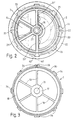
- FIG. 2 is a plan-view of the distributor according to the present invention from below of the cover with the obturator bell;
- FIG. 3 is a plan-view of the base body without the outlets for the liquid
- FIG. 4 illustrates in a perspective view a detail view of an edge of the open top of the base body above which is shown the corresponding edge of the cover which engages it as per a bayonet coupling arrangement, and also a piece assuring said engagement;
- FIG. 5 is a sectional elevation of the ensemble of elements of FIG. 4 already fitted together.
- FIGS. 6 and 7 shows a perspective view of the distributor and an alternative arrangement of the latter, respectively.
- the distributor for liquids comprises a base body 1 having a cylindrical configuration and being upperly open, said body having two portions of different diameter, the diameter of the upper portion 1 a being bigger than that of the lower portion 1 b , this latter being radially compartmented.
- the base body 1 Onto the base body 1 is fitted as per a bayonet coupling arrangement a cover 2 after having introduced into said base body an obturator bell 3 resting on the lower portion 1 b of said body, the inner space of the upper portion 1 a constituting the liquid admission chamber provided to receive the liquid flowing into it through a lateral inlet duct or opening 4 .
- the compartmented inner space of the lower portion 1 b does in its turn constitute the distributing chamber itself provided to distribute the liquid to one or another of respective outlet openings or ducts 5 laterally or inferiorly provided in the compartments of said distributing chamber, said liquid flowing into one or another of said compartments through an opening 6 of the bell 3 which after a previous rotational manipulation of said bell is then arranged on the selected compartment.
- the handle 9 plays through its end 9 ′ on a friction washer 10 housed in a discoidal recess 10 ′ of the cover 2 and upperly flush with the top flat surface of said cover, said end 9 ′ resting on said washer 10 in the passive position of the handle 9 with its also flat lower face.
- the cover 2 has an annular salient 11 comprising radial slots 11 ′ into one of which a radial appendage 12 will be introduced which is provided on the end 9 ′ of the handle 9 in order to thus stabilize the position chosen for the bell 3 , said handle 9 also comprising a lower protrusion 13 coming into abutment with the cover 2 when said handle is actuated in a downward direction.
- the bell 3 rests on the inner peripheral step 18 defined by the two portions of the body 1 , and also on the edges of the core 17 and of the compartmenting partitions 19 , said resting condition being accomplished through a doubly annular seal 20 , 21 provided with radial lengths 21 ′ and partially inlaid in circular grooves 22 , 23 provided in concentric annular edges of said bell 3 , and in radial grooves 23 ′ of this latter.
- the former For the attachment as per a bayonet coupling of the cover 2 onto the base body 1 the former comprises a double, peripheral flange 32 extending in an outward and downward direction and innerly having a number of L-shaped recesses 33 into which corresponding protrusions 34 will penetrate and slide, said protrusions being externally provided below the peripheral recess 31 on the open top of said base body 1 .
- the closure of the distributor is assured with a piece 35 provided to be removably fitted into a recess 36 externally provided in the flange 32 of the cover 2 above one of the inner recesses 33 (see FIGS. 4 and 5) after having previously introduced a vertically downcoming shank 37 provided on said piece 35 into an orifice 38 of said recess 36 , said shank having thus been fitted by way of a cotter between respective grooves 39 , 40 of one of the outer protrusions 34 of the open top of the base body 1 and of the inner face of the flange 32 of the cover 2 , said shank being thus placed within the corresponding recess 33 .
- the piece 35 has a lip 41 that is parallel to the shank 37 and has an inner end catch 41 ′ provided to prevent an accidental detachment of said piece 35 , said catch 41 ′ engaging the small step formed by a vertically provided cul-de-sac slot 42 of the flange 32 of the cover 2 .
- the base body 1 does also have in the upper portion 1 a an outlet opening 43 closed with a plug 44 and provided for receiving the installation of a manometer and/or a purger, whereas the lower portion 1 b is provided with a lateral, cylindrical sight 43 in one of the outlet ducts 5 .
- the distributor can be used, among other applications, in the swimming pool facilities, being in this case fitted to the associated filter body in a lateral arrangement or also on top of this latter, in which case the lower portion 1 b of the distributor's base body 1 will inferiorly end in a stepped flange 45 (as illustrated with dash lines in FIG. 1 and as shown by the alternative arrangement of FIG. 7) and a diffuser 46 (FIG. 7 ).
Abstract
Description
Claims (6)
Priority Applications (1)
| Application Number | Priority Date | Filing Date | Title |
|---|---|---|---|
| US09/483,975 US6173743B1 (en) | 2000-01-18 | 2000-01-18 | Distributor for liquids |
Applications Claiming Priority (1)
| Application Number | Priority Date | Filing Date | Title |
|---|---|---|---|
| US09/483,975 US6173743B1 (en) | 2000-01-18 | 2000-01-18 | Distributor for liquids |
Publications (1)
| Publication Number | Publication Date |
|---|---|
| US6173743B1 true US6173743B1 (en) | 2001-01-16 |
Family
ID=23922233
Family Applications (1)
| Application Number | Title | Priority Date | Filing Date |
|---|---|---|---|
| US09/483,975 Expired - Lifetime US6173743B1 (en) | 2000-01-18 | 2000-01-18 | Distributor for liquids |
Country Status (1)
| Country | Link |
|---|---|
| US (1) | US6173743B1 (en) |
Cited By (27)
| Publication number | Priority date | Publication date | Assignee | Title |
|---|---|---|---|---|
| US20040045613A1 (en) * | 2002-09-06 | 2004-03-11 | Waterway Plastics, Inc. | Diverter valve |
| US20040118763A1 (en) * | 2002-07-25 | 2004-06-24 | Sacopa, S.A.U. | Swimming pool filter |
| EP1617119A1 (en) * | 2004-07-14 | 2006-01-18 | Valvules i Racords Canovelles, S.A. | A distributor for liquids |
| US20070295036A1 (en) * | 2004-08-23 | 2007-12-27 | Reckitt Benckiser N.V. | Detergent Dispensing Device |
| EP1918251A1 (en) | 2006-10-31 | 2008-05-07 | Pentair Water Belgium BVBA | A water distributor for a multiport valve, a multiport valve including said distributor and a filter including said valve |
| US20080210309A1 (en) * | 2007-03-01 | 2008-09-04 | Randy Tan | Diverter valve |
| US20080293604A1 (en) * | 2005-11-07 | 2008-11-27 | Reckitt Benckiser N.V. | Dosage Element |
| US20090235959A1 (en) * | 2005-11-07 | 2009-09-24 | Reckitt Benckiser N.V. | Assembly and Device |
| US20090242812A1 (en) * | 2008-03-31 | 2009-10-01 | Valvules I Racords Canovelles, S.A. | Liquid distributor valve |
| US20100031978A1 (en) * | 2006-10-30 | 2010-02-11 | Reckitt Benckiser N.V. | Multi-Dosing Detergent delivery device |
| US20100065084A1 (en) * | 2006-01-21 | 2010-03-18 | Reckitt Benckiser N.V. | Multi-Dosing Detergent Delivery Device |
| US20100089422A1 (en) * | 2006-10-30 | 2010-04-15 | Reckitt Benckiser Nv | Multi-Dosing Detergent Delivery Device |
| US20100104488A1 (en) * | 2006-10-30 | 2010-04-29 | Reckitt Benckiser N. | Multi-Dosing Detergent Delivery Device |
| US20100135874A1 (en) * | 2006-10-30 | 2010-06-03 | Reckitt Benckiser N.V. | Multi-Dosing Detergent Delivery Device |
| US20100155428A1 (en) * | 2006-10-30 | 2010-06-24 | Reckitt Benckiser Nv | Mounting Device |
| US20100170302A1 (en) * | 2006-10-30 | 2010-07-08 | Reckitt Benckiser N.V. | Multi-Dosing Detergent Delivery Device |
| US20100179087A1 (en) * | 2006-10-30 | 2010-07-15 | Reckitt Benckiser Production (Poland) sp.z.o.o | Compressed Detergent Composition |
| US20100200025A1 (en) * | 2007-05-30 | 2010-08-12 | Reckitt Benckiser N.V. | Detergent Dosing Device |
| WO2010121911A1 (en) * | 2009-04-22 | 2010-10-28 | Robert Bosch Gmbh | Valve for controlling a flow |
| US20110272435A1 (en) * | 2004-08-23 | 2011-11-10 | Reckitt Benckiser N.V. | Detergent Dispensing Device |
| US8146609B2 (en) | 2006-10-30 | 2012-04-03 | Reckitt Benckiser N.V. | Device status indicator for a multi-dosing detergent delivery device |
| USD663911S1 (en) | 2009-07-22 | 2012-07-17 | Reckitt Benckiser N.V. | Detergent dispensing device lid |
| US8338357B2 (en) | 2006-01-21 | 2012-12-25 | Reckitt Benckiser N.V. | Multiple dosing ware washing article |
| US8375962B2 (en) | 2006-01-21 | 2013-02-19 | Reckitt Benckiser N. V. | Dosage element and chamber |
| US8815018B2 (en) | 2007-05-30 | 2014-08-26 | Reckitt Benckiser N.V. | Detergent dosing device |
| US20220390026A1 (en) * | 2021-06-08 | 2022-12-08 | Robert Bosch Gmbh | Rotary Disc Valve |
| US20230184338A1 (en) * | 2021-12-15 | 2023-06-15 | Robert Bosch Gmbh | Rotary Disc Valve |
Citations (4)
| Publication number | Priority date | Publication date | Assignee | Title |
|---|---|---|---|---|
| US2253020A (en) * | 1938-01-29 | 1941-08-19 | Lee G Daniels | Valve structure |
| US2451678A (en) * | 1945-04-04 | 1948-10-19 | Automatic Pump & Softener Corp | Multiple port valve structure |
| US3640310A (en) * | 1969-06-26 | 1972-02-08 | Hayward Mfg Co Inc | Multiport valve |
| US3911956A (en) * | 1973-09-24 | 1975-10-14 | Pacific Fabrication Inc | Multiport valve |
-
2000
- 2000-01-18 US US09/483,975 patent/US6173743B1/en not_active Expired - Lifetime
Patent Citations (4)
| Publication number | Priority date | Publication date | Assignee | Title |
|---|---|---|---|---|
| US2253020A (en) * | 1938-01-29 | 1941-08-19 | Lee G Daniels | Valve structure |
| US2451678A (en) * | 1945-04-04 | 1948-10-19 | Automatic Pump & Softener Corp | Multiple port valve structure |
| US3640310A (en) * | 1969-06-26 | 1972-02-08 | Hayward Mfg Co Inc | Multiport valve |
| US3911956A (en) * | 1973-09-24 | 1975-10-14 | Pacific Fabrication Inc | Multiport valve |
Cited By (47)
| Publication number | Priority date | Publication date | Assignee | Title |
|---|---|---|---|---|
| US20040118763A1 (en) * | 2002-07-25 | 2004-06-24 | Sacopa, S.A.U. | Swimming pool filter |
| US7081200B2 (en) * | 2002-07-25 | 2006-07-25 | Sacopa, S.A.U. | Swimming pool filter |
| US20040045613A1 (en) * | 2002-09-06 | 2004-03-11 | Waterway Plastics, Inc. | Diverter valve |
| CN100434778C (en) * | 2004-07-14 | 2008-11-19 | 瓦尔乌斯·艾·若克德斯·坎乌尔斯公司 | A distributor for liquids |
| EP1617119A1 (en) * | 2004-07-14 | 2006-01-18 | Valvules i Racords Canovelles, S.A. | A distributor for liquids |
| US20060011244A1 (en) * | 2004-07-14 | 2006-01-19 | Ibanez Sapina Miguel | Distributor for liquids |
| US20070295036A1 (en) * | 2004-08-23 | 2007-12-27 | Reckitt Benckiser N.V. | Detergent Dispensing Device |
| US8221696B2 (en) | 2004-08-23 | 2012-07-17 | Reckitt Benckiser N.V. | Detergent dispensing device |
| US20100176148A1 (en) * | 2004-08-23 | 2010-07-15 | Reckitt Benckiser N.V. | Detergent Dispensing Device |
| US20080274025A1 (en) * | 2004-08-23 | 2008-11-06 | Reckitt Benckiser N.V. | Detergent Dispensing Device |
| US20110272435A1 (en) * | 2004-08-23 | 2011-11-10 | Reckitt Benckiser N.V. | Detergent Dispensing Device |
| US20080168804A1 (en) * | 2004-08-23 | 2008-07-17 | Reckitt Benckiser N.V. | Detergent Dispensing Device |
| US20080308570A1 (en) * | 2004-08-23 | 2008-12-18 | Reckitt Benckiser N.V. | Detergent Dispensing Device |
| US20090044575A1 (en) * | 2004-08-23 | 2009-02-19 | Reckitt Benckiser N.V. | Detergent Dispensing Device |
| US20090104093A1 (en) * | 2004-08-23 | 2009-04-23 | Reckitt Benckiser N.V. | Detergent dispensing device |
| US20090235959A1 (en) * | 2005-11-07 | 2009-09-24 | Reckitt Benckiser N.V. | Assembly and Device |
| US20080293604A1 (en) * | 2005-11-07 | 2008-11-27 | Reckitt Benckiser N.V. | Dosage Element |
| US20100212695A1 (en) * | 2005-11-07 | 2010-08-26 | Reckitt Benckiser N.V. | Dosage Element |
| US8375962B2 (en) | 2006-01-21 | 2013-02-19 | Reckitt Benckiser N. V. | Dosage element and chamber |
| US20100065084A1 (en) * | 2006-01-21 | 2010-03-18 | Reckitt Benckiser N.V. | Multi-Dosing Detergent Delivery Device |
| US8338357B2 (en) | 2006-01-21 | 2012-12-25 | Reckitt Benckiser N.V. | Multiple dosing ware washing article |
| US20100155428A1 (en) * | 2006-10-30 | 2010-06-24 | Reckitt Benckiser Nv | Mounting Device |
| US8146609B2 (en) | 2006-10-30 | 2012-04-03 | Reckitt Benckiser N.V. | Device status indicator for a multi-dosing detergent delivery device |
| US20100170302A1 (en) * | 2006-10-30 | 2010-07-08 | Reckitt Benckiser N.V. | Multi-Dosing Detergent Delivery Device |
| US20100104488A1 (en) * | 2006-10-30 | 2010-04-29 | Reckitt Benckiser N. | Multi-Dosing Detergent Delivery Device |
| US20100179087A1 (en) * | 2006-10-30 | 2010-07-15 | Reckitt Benckiser Production (Poland) sp.z.o.o | Compressed Detergent Composition |
| US20100135874A1 (en) * | 2006-10-30 | 2010-06-03 | Reckitt Benckiser N.V. | Multi-Dosing Detergent Delivery Device |
| US20100089422A1 (en) * | 2006-10-30 | 2010-04-15 | Reckitt Benckiser Nv | Multi-Dosing Detergent Delivery Device |
| US8146610B2 (en) | 2006-10-30 | 2012-04-03 | Reckitt Benckiser N.V. | Multi-dosing detergent delivery device |
| US8329112B2 (en) | 2006-10-30 | 2012-12-11 | Reckitt Benckiser N.V. | Multi-dosing detergent delivery device |
| US20100031978A1 (en) * | 2006-10-30 | 2010-02-11 | Reckitt Benckiser N.V. | Multi-Dosing Detergent delivery device |
| EP1918251A1 (en) | 2006-10-31 | 2008-05-07 | Pentair Water Belgium BVBA | A water distributor for a multiport valve, a multiport valve including said distributor and a filter including said valve |
| US7849877B2 (en) * | 2007-03-01 | 2010-12-14 | Zodiac Pool Systems, Inc. | Diverter valve |
| US8910662B2 (en) | 2007-03-01 | 2014-12-16 | Zodiac Pool Systems, Inc. | Diverter valve |
| US20080210309A1 (en) * | 2007-03-01 | 2008-09-04 | Randy Tan | Diverter valve |
| US8815018B2 (en) | 2007-05-30 | 2014-08-26 | Reckitt Benckiser N.V. | Detergent dosing device |
| US20100200025A1 (en) * | 2007-05-30 | 2010-08-12 | Reckitt Benckiser N.V. | Detergent Dosing Device |
| US8171957B2 (en) * | 2008-03-31 | 2012-05-08 | Valvules I Racords Canovelles, S.A. | Liquid distributor valve |
| CN101551037B (en) * | 2008-03-31 | 2012-10-10 | 瓦尔乌斯·艾·若克德斯·坎乌尔斯公司 | Liquid distributor valve |
| US20090242812A1 (en) * | 2008-03-31 | 2009-10-01 | Valvules I Racords Canovelles, S.A. | Liquid distributor valve |
| CN102414491A (en) * | 2009-04-22 | 2012-04-11 | 罗伯特·博世有限公司 | Valve for controlling flow |
| WO2010121911A1 (en) * | 2009-04-22 | 2010-10-28 | Robert Bosch Gmbh | Valve for controlling a flow |
| USD670468S1 (en) | 2009-07-22 | 2012-11-06 | Reckitt Benckiser N.V. | Detergent dispensing device lid |
| USD663911S1 (en) | 2009-07-22 | 2012-07-17 | Reckitt Benckiser N.V. | Detergent dispensing device lid |
| US20220390026A1 (en) * | 2021-06-08 | 2022-12-08 | Robert Bosch Gmbh | Rotary Disc Valve |
| US11585451B2 (en) * | 2021-06-08 | 2023-02-21 | Robert Bosch Llc | Rotary disc valve |
| US20230184338A1 (en) * | 2021-12-15 | 2023-06-15 | Robert Bosch Gmbh | Rotary Disc Valve |
Similar Documents
| Publication | Publication Date | Title |
|---|---|---|
| US6173743B1 (en) | Distributor for liquids | |
| US5458154A (en) | Spout mounting system | |
| RU2672831C2 (en) | Lid with check valve | |
| US7407148B2 (en) | Rotary valve assembly for fluid filtration system | |
| US2890816A (en) | Multiple condiment dispensing unit | |
| US4277004A (en) | Cover and aerosol activator for aerosol spray can | |
| US4382520A (en) | Flow control structures | |
| US2075443A (en) | Combined strainer and valve | |
| US4091955A (en) | Plastic filler neck cap | |
| US3726317A (en) | Bottom outlet grommet mixing valve | |
| RU2001101458A (en) | Aerosol valve for dispensing a product including powder and / or other solid particles from an aerosol can | |
| US6227246B1 (en) | Faucet mixing valve housing with check valves and filter | |
| US2313266A (en) | Theftproof closure | |
| US2997054A (en) | Vacuum breaker | |
| US3392838A (en) | Filter for fluids | |
| US6299024B1 (en) | Valve assembly for dispensing container | |
| US2801032A (en) | Dispensing valve units | |
| EP0022345B1 (en) | A valve for a pressurized dispensing container | |
| US2709624A (en) | Sprinkler attachment for garden hose | |
| JP6025698B2 (en) | Water discharge structure and water supply device | |
| US6382229B1 (en) | Valve assembly and seal therefor | |
| US2740229A (en) | Powder dispenser | |
| US1105993A (en) | Sprayer. | |
| US2148864A (en) | Unitary bottle closure | |
| JP2011235772A (en) | Fuel shut-off valve |
Legal Events
| Date | Code | Title | Description |
|---|---|---|---|
| AS | Assignment |
Owner name: VALVULES I RACORDS CANOVELLES, S.A., SPAIN Free format text: ASSIGNMENT OF ASSIGNORS INTEREST;ASSIGNOR:IBANEZ SAPINA, MIGUEL;REEL/FRAME:010518/0891 Effective date: 19991116 |
|
| FEPP | Fee payment procedure |
Free format text: PAYOR NUMBER ASSIGNED (ORIGINAL EVENT CODE: ASPN); ENTITY STATUS OF PATENT OWNER: SMALL ENTITY |
|
| STCF | Information on status: patent grant |
Free format text: PATENTED CASE |
|
| FPAY | Fee payment |
Year of fee payment: 4 |
|
| FPAY | Fee payment |
Year of fee payment: 8 |
|
| FPAY | Fee payment |
Year of fee payment: 12 |
|
| AS | Assignment |
Owner name: CEPEX, S.A.U., SPAIN Free format text: ASSIGNMENT OF ASSIGNORS INTEREST;ASSIGNOR:VALVULES I RACORDS CANOVELLES, S.A.;REEL/FRAME:063423/0371 Effective date: 20230310 |