US6167502A - Method and apparatus for manifold array processing - Google Patents
Method and apparatus for manifold array processing Download PDFInfo
- Publication number
- US6167502A US6167502A US08/949,122 US94912297A US6167502A US 6167502 A US6167502 A US 6167502A US 94912297 A US94912297 A US 94912297A US 6167502 A US6167502 A US 6167502A
- Authority
- US
- United States
- Prior art keywords
- cluster
- pes
- hypercube
- communications
- data
- Prior art date
- Legal status (The legal status is an assumption and is not a legal conclusion. Google has not performed a legal analysis and makes no representation as to the accuracy of the status listed.)
- Expired - Lifetime
Links
Images


Classifications
-
- G—PHYSICS
- G06—COMPUTING; CALCULATING OR COUNTING
- G06F—ELECTRIC DIGITAL DATA PROCESSING
- G06F15/00—Digital computers in general; Data processing equipment in general
- G06F15/76—Architectures of general purpose stored program computers
- G06F15/80—Architectures of general purpose stored program computers comprising an array of processing units with common control, e.g. single instruction multiple data processors
- G06F15/8007—Architectures of general purpose stored program computers comprising an array of processing units with common control, e.g. single instruction multiple data processors single instruction multiple data [SIMD] multiprocessors
- G06F15/8023—Two dimensional arrays, e.g. mesh, torus
Definitions
- the present invention relates generally to improvements in data processing systems and methods and, more particularly, to improved parallel data processing architectures.
- each path MP may include T transmit wires and R receive wires or as illustrated in FIG. 1C, each path MP may include B bidirectional wires.
- K wires the total number of bus wires excluding control signals, in a path
- K the total number of bus wires excluding control signals, in a path
- K the total number of bus wires excluding control signals, in a path
- K the total number of bus wires excluding control signals, in a path
- K the total number of bus wires excluding control signals, in a path
- K the total number of bus wires excluding control signals, in a path
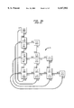
- the conventional torus-connected array of FIG. 1A includes sixteen processing elements connected in a four by four array 10 of PEs. Each processing element PE i ,j is labeled with its row and column number i and j, respectively. Each PE communicates to its nearest North (N), South (S), East (E) and West (W) neighbor with point to point connections. For example, the connection between PE 0 ,0 and PE 3 ,0 shown in FIG.
- each row contains a set of N interconnections and, with N rows, there are N 2 horizontal connections. Similarly, with N columns having N vertical interconnections each, there are N 2 vertical interconnections.
- N 4.
- the total number of wires, such as the metallization lines in an integrated circuit implementation in a N ⁇ N torus-connected computer, including wraparound connections, is therefore 2kN 2 , where k is the number of wires in each interconnection.
- each PE can be a separate microprocessor chip, for example. Since the total number of wires in a torus connected computer can be significant, the interconnections may consume a great deal of valuable integrated circuit "real estate", or the area of the chip taken up. Additionally, the PE interconnection paths quite frequently cross over one another complicating the IC layout process and possibly introducing noise to the communications lines through crosstalk. Furthermore, the length of wraparound links, which connect PEs at the North and South and at the East and West extremes of the array, increase with increasing array size. This increased length increases each communication line's capacitance, thereby reducing the line's maximum bit rate and introducing additional noise to the line.
- torus array Another disadvantage of the torus array arises in the context of transpose operations. Since a processing element and its transpose are separated by at least one intervening processing element in the communications path, latency is introduced in operations which employ transposes. For example, should the PE 2 ,1 require data from its transpose, the PE 1 ,2, the data must travel through the intervening PE 1 ,1 or P 2 ,2. Naturally, this introduces a delay into the operation, even if PE 1 ,1 and PE 2 ,2 are not otherwise occupied.
- PEs are implemented as microprocessor elements
- Such delays snowball with every intervening PE and significant latency is introduced for the most distant of the transpose pairs. For example the PE 3 ,1 /PE 1 ,3 transpose pair of FIG.
- the operative technique of these torus array organizations is the folding of arrays of PEs using the diagonal PEs of the conventional nearest neighbor torus as the foldover edge. As illustrated in the array 20 of FIG. 2A, these techniques may be employed to substantially reduce inter-PE wiring, to reduce the number and length of wraparound connections, and to position PEs in close proximity to their transpose PEs.
- This processor array architecture is disclosed, by way of example, in U.S. Pat. No. 5,577,262, U.S. Pat. No. 5,612,908 and EP 0,726,532 and EP 0,726,529 which are incorporated herein by reference in their entirety.
- While such arrays provide substantial benefits over the conventional torus architecture, due to the irregularity of PE combinations, for example in a single fold diagonal fold mesh, some PEs are clustered in groups of two while others are single. In a three fold diagonal fold mesh, there are clusters of four PEs and eight PEs. Due to the overall triangular shape of the arrays, the diagonal fold type of array presents substantial obstacles to efficient, inexpensive integrated circuit implementation. Additionally, in a diagonal fold mesh and other conventional mesh architectures, the interconnection topology is inherently part of the PE definition. This approach fixes the PE's position in the topology, consequently limiting the topology of the PEs and their connectivity to the fixed configuration that is implemented.
- the connections can be modeled geometrically or arithmetically.
- the PEs correspond to the corners of a d-dimensional hypercube and the links correspond to the edges of the hypercube.
- each PE is assigned a unique binary index from 0 through d-1. Any two PEs are connected only if the binary representations of their indices differ in exactly 1 bit position.
- the geometric and arithmetic models can be related to one another by associating each of the d dimensions with a unique bit position. The property of having indices that differ in one bit position is then equivalent to occupying corresponding corners of two (d-1)-dimensional hypercubes.
- a PE may be assigned a label indicative of its position within the topology. This label ⁇ D 0 , D 1 , . . .
- D r-1 ⁇ is a binary representation where each digit indicates an r-dimensional connection path available for communications on the r-D hypercube.
- Each node in the hypercube is at most one digit D different from its directly connected nodes.
- the longest path in the hypercube is between a PE ⁇ D 0 , D 1 , . . . D r-1 ⁇ and its complement ⁇ D 0 , D 1 , . . . D r-1 ⁇ , for example, PE 101101, and PE 010010.
- Hypercube topologies are discussed in Robert Cypher and Jorge L. C. Sanz, "The SIMD Model of Parallel Computation" 1994 Springer-Verlag, N.Y., pp. 61-68 and F.
- Multi-dimensional hypercubes may be mapped onto a torus, a diagonal-fold torus, or other PE arrangements. Such mappings will be discussed briefly below.
- the bidirectional tri-state links support signal source generation at multiple points on a link, under a control scheme that prevents data collisions on the link.
- the unidirectional links use a point to point single source, single receiver pair for any interfacing signals.
- bit-serial and multi-bit parallel implementations are also contemplated.
- a hypercube may be mapped onto a torus in which the 2-dimensional torus is made up of Processor Elements (PEs), and as, illustrated in FIGS. 1A and 1D, each PE has associated with it a torus node (row and column), as indicated by the top PE label, and a hypercube PE number that is indicated by the bottom label within each PE.
- the hypercube PE number or node address is given as an r-digit representation for an r-dimensional (rD) hypercube in which each digit represents a connectivity dimension.
- rD r-dimensional
- FIG. 1A encodes the PE i ,j node with a Gray code encoding PE G (i),G(j), which is a sequence in which only a single binary digit changes between sequential numbers. For example, the decimal sequence 0, 1, 2, 3, would be written 00, 01, 10, 11 in a binary sequence, while the Gray code sequence would be 00, 01, 11, 10.
- FIG. 1D shows an alternative hypercube mapping onto a nearest neighbor torus.
- the Cosmic Cube was implemented with Intel 8086 processors running in a Multiple Instruction Multiple Data (MIMD) mode and using message passing to communicate between hypercube connected processors.
- MIMD Multiple Instruction Multiple Data
- Another hypercube implementation, the NCUBE consists, in one large configuration, of a 10-D hypercube using custom processor chips that form nodes of the hypercube.
- the NCUBE is a MIMD type of machine but also supports a Single Program Multiple Data (SPMD) mode of operation where each node processor has a copy of the same program and can therefore independently process different conditional code streams.
- SPMD Single Program Multiple Data
- the Connection Machine (CM) built by Thinking Machines Corporation, was another hypercube implementation.
- the initial, CM-1, machine was a 12D-hypercube with each node including a 4 ⁇ 4 grid of bit-serial processing cells.
- each processing element must have at least one bidirectional data port for each hypercube dimension
- one aspect of the present invention is that our PEs are decoupled from the network topology needing only one input port and one output port.
- each additional hypercube dimension increases the number of ports in each PE, the design of each PE soon becomes unwieldy, with an inordinate percentage of the PE devoted to data ports. Additionally, communications between complement PEs become burdened by greater and greater latency as the "diameter", that is, the number of communication steps between complement PEs, of a hypercube expands. In other words, providing a connection between a node address and its complement, the longest paths between hypercube PE nodes, would be difficult and costly to obtain and would certainly not be scalable.
- the present invention is directed to an array of processing elements which improves the connectivity among the processing elements while it substantially reduces the array's interconnection wiring requirements when compared to the wiring requirements of conventional torus or hypercube processing element arrays.
- one array in accordance with the present invention, achieves a substantial reduction in the latency of transpose operations and latency of communications between a PE node and it hypercube complement node.
- the inventive array de-couples the length of wraparound wiring from the array's overall dimensions, thereby reducing the length of the longest interconnection wires.
- only one transmit port and one receive port are required per PE, independent of the number of neighborhood connections a particular topology may require of its PE nodes.
- a preferred integrated circuit implementation of the array includes a combination of similar processing element clusters combined to present a rectangular or square outline.
- the similarity of processing elements, the similarity of processing element clusters, and the regularity of the array's overall outline make the array particularly suitable for cost-effective integrated circuit manufacturing.
- processing elements may first be combined into clusters which capitalize on the communications requirements of single instruction multiple data (“SIMD") operations.
- SIMD single instruction multiple data
- Processing elements are then completely connected within the cluster.
- Processing elements may then be grouped so that the elements of one cluster communicate within a cluster and with members of only two other clusters.
- each cluster's constituent processing elements communicate in only two mutually exclusive directions with the processing elements of each of the other clusters.
- SIMD torus with unidirectional capability
- North/South directions are mutually exclusive with the East/West directions.
- Processing element clusters are, as the name implies, groups of processors formed preferably in close physical proximity to one another.
- the processing elements of a cluster preferably would be laid out as close to one another as possible, and preferably closer to one another than to any other processing element in the array.
- an array corresponding to a conventional four by four torus array of processing elements may include four clusters of four elements each, with each cluster communicating only to the North and East with one other cluster and to the South and West with another cluster, or to the South and East with one other cluster and to the North and West with another cluster.
- the PEs comprising a cluster are chosen so that processing elements, their transposes and the hypercube complement PEs are located in the same cluster and communicate with one another through intra-cluster communication paths, thereby eliminating the latency associated with transpose operations carried out on conventional torus arrays and communication between hypercube complement PEs carried out on a conventional hypercube array. Additionally, since the conventional wraparound path is treated the same as any PE-to-PE path, the longest communications path may be as short as the inter-cluster spacing, regardless of the array's overall dimension.
- Each PE contains a virtual PE address storage unit and a configuration controller.
- the virtual PE number and configuration control information are combined to determine the settings of cluster switches and to thereby reconfigure the PE array's topology.
- This reconfiguration may be in response to a dispactched instruction from a controller, for example.
- PEs within an array are clustered so that a PE and its transpose are combined within a cluster and a PE and its hypercube complement are contained within the same cluster.
- the dynamic reconfiguration in combination with cluster switches which permit complete inter-PE connectivity within each cluster, provides the ability to reconfigure the array into a wide variety of topologies.
- the PEs in a cluster may advantageously have the same interface to the cluster switch which completely connects the PEs within the cluster and allows each virtual PE, within the cluster, the same access to two external orthogonal clusters.
- the cluster switch which completely connects the PEs within the cluster and allows each virtual PE, within the cluster, the same access to two external orthogonal clusters.
- enhanced connectivity hypercube may be provided in which each cluster of 4 nodes has only 4 output buses, each with a fanout of 3, one internal to the switch and one for each of the orthogonal clusters. From the receive side there are three signals being received per virtual node, one internal to the switch and one from each of the orthogonal clusters.
- FIG. 1A is a block diagram of a prior art 4 ⁇ 4 nearest neighbor connected torus processing element (PE) array
- FIG. 1B illustrates how the prior art torus connection paths of FIG. 1A may include T transmit and R receive wires;
- FIG. 1C illustrates how prior art torus connection paths of FIG. 1A may include B bidirectional wires
- FIG. 1D is a block diagram of a second prior art 4 ⁇ 4 nearest neighbor connected torus PE array.
- FIGS. 2A and 2B are block diagrams of prior art folded PE arrays
- FIGS. 3A-3C are block diagrams of processing elements which may suitably be employed within PE arrays in accordance with the present invention.
- FIG. 3D illustrates further aspects of cluster switch control according to the present invention.
- FIG. 4 is a block diagram illustrating the clustering of PEs within a manifold array, and the inter-cluster communications of PEs;
- FIG. 5 is a block diagram of an individual PE cluster from FIG. 4, showing further details of a cluster switch;
- FIG. 6 is a block diagram of an improved PE cluster in the present invention, along with an improved cluster switch;
- FIG. 7 is a block diagram which illustrates the interconnection paths between PE clusters in greater detail
- FIG. 8A is a block diagram which illustrates a cluster switch implementation that does not include buffers
- FIGS. 8B and 8C are block diagrams which illustrates the interconnection paths between PE clusters in greater detail, using cluster switches that do not include buffers;
- FIG. 9A is a block diagram of a 2 ⁇ 2 cluster showing the interconnection paths to the other orthogonal 2 ⁇ 2 clusters making up a large array;
- FIG. 9B is a block diagram of a 2 ⁇ 2 manifold array
- FIG. 10 is a block diagram which illustrates the East communication paths for a 4 ⁇ 4 torus
- FIG. 11 is a block diagram which illustrates the West communication paths for a 4 ⁇ 4 torus
- FIG. 12 is a block diagram which illustrates the North communication paths for a 4 ⁇ 4 torus
- FIG. 13 is a block diagram which illustrates the South communication paths for a 4 ⁇ 4 torus
- FIG. 14 is a block diagram which illustrates the transpose communication paths for a 4 ⁇ 4 manifold array
- FIG. 15 is a block diagram which illustrates four independent 1 ⁇ 4 linear rings on a 4 ⁇ 4 manifold array
- FIG. 16 is a block diagram which illustrates the communications paths for a z-axis send operation in an array configuration
- FIG. 17 is a block diagram which illustrates the hypercube node labeling of a 4 ⁇ 4 manifold array
- FIG. 18 is a block diagram illustrating of a 4 ⁇ 4 manifold array hypercube complement communication
- FIG. 19 is a block diagram illustrating of a 5D hypercube
- FIG. 20 is a block diagram illustrating of a 5D hypercube mapped onto a manifold array
- FIG. 21A is a Table indicating the node elements of a 4D hypercube embedded onto a torus
- FIG. 21B is an improved manifold array table indicating placement of embedded hypercube nodes
- FIG. 22 is a 4 ⁇ 4 ⁇ 4 representation after 1D down rotation of columns
- FIG. 23 is a 4 ⁇ 4 ⁇ 4 z plane representation of the nodes of FIG. 22;
- FIG. 24 is a 4 ⁇ 4 ⁇ 4 z plane representation after 1D down rotation of columns
- FIG. 25 is a reordering of z plane representation for layout connectivity
- FIG. 26 illustrates the separation of the z planes into 2 ⁇ 2 subclusters
- FIG. 27A shows the interconnection of the 2 ⁇ 2 subclusters into four 4 ⁇ 4 manifold arrays
- FIG. 27B shows an example o f a 4 ⁇ 4 ⁇ 4 PE node input (receive) connectivity
- FIG. 28A is a block diagram of a 4 ⁇ 4 manifold array block diagram showing a single controller per cluster configuration and an exemplary interface;
- FIG. 28B shows the 4 ⁇ 4 multiple controller manifold array of FIG. 28A receiving 32 data items into its external interface
- FIG. 29 shows the 4 ⁇ 4 multiple controller manifold array of FIG. 28A illustrating the loading of 32 data items of the example into the four memory controllers;
- FIG. 30 shows the 4 ⁇ 4 multiple controller manifold array of FIG. 28A illustrating the load distribution of the 32 data items to the individual PEs in each cluster;
- FIG. 31 lists the 32 exemplary data items after each step of the perfect shuffle example with reference to FIGS. 28A-30;
- FIG. 32 shows a 4 ⁇ 4 manifold array illustrating the paths the data takes between PEs to execute a Swap North communication operation and the results in the PE register at completion of the communication operation of the perfect shuffle example
- FIG. 33 shows a 4 ⁇ 4 manifold array illustrating the paths the data takes between PEs to execute a Swap-South communication operation and the results in the PE registers at completion of the communication operation of the perfect shuffle example.
- a manifold array processor in accordance with the present invention combines PEs in clusters, or groups, such that the elements of one cluster communicate directly with members of only two other clusters and each cluster's constituent processing elements communicate directly in only two mutually exclusive directions with the processing elements of each of the other clusters.
- clustering PEs in this manner communications paths between PE clusters may be shared, thus substantially reducing the interconnection wiring required for an array.
- each PE may have a single transmit port and a single receive port or, in the case of a bidirectional, sequential or time-sliced communications implementation, a single transmit/receive port. As a result, the individual PE are de-coupled from the array architecture.
- each PE may simultaneously transmit and receive. In a conventional 6D hypercube, this would require six transmit and six receive ports, a total of twelve data ports, for each PE. With the present invention, only one transmit- and one receive-port, a total of two data ports are required, regardless of the hypercube's dimension. As noted above, the transmit and receive data ports may be combined into one transmit/receive data port if bidirectional, sequential or time-sliced data communications are employed. Each PE contains a virtual PE storage unit and a configuration control unit.
- the virtual PE number and configuration control information are combined to determine the settings of cluster switches, to control the direction of communications, and to reconfigure the PE array's topology. This reconfiguration may be in response to a dispatched instruction from a controller, for example.
- PEs within an array are clustered so that a PE and its transpose are combined within a cluster and a PE and its hypercube complement are contained with the same cluster.
- the PEs comprising a cluster are chosen so that processing elements and their transposes are located in the same cluster and communicate with one another through intra-cluster communication paths.
- processing elements are referred to as they would appear in a conventional torus array, for example, processing element PE 0 ,0 is the processing element that would appear in the "Northwest" corner of a conventional torus array, or, in other words, in row 0 and column 0. Consequently, although the layout of the new cluster array is substantially different from that of a conventional array processor, the same data would be supplied to corresponding processing elements of the conventional torus and new cluster arrays.
- the 0,0 element of the new cluster array would receive the same data to operate on as the 0,0 element of a conventional torus-connected array.
- the directions referred to in this description will be in reference to the directions of a torus-connected array. For example, when communications between processing elements are said to take place from North to South, those directions refer to the direction of communication within a conventional torus-connected array.
- FIG. 3A shows the basic structure of a PE 40 illustrating one suitable embodiment which may be utilized for each PE for the new PE array of the present invention. For simplicity of illustration, interface logic and buffers are not shown.
- An instruction bus 31 is connected to receive dispatched instructions from a SIMD controller 29, a data bus 32 is connected to receive data from memory 33 or another data source external to the PE 40.
- a register file storage medium 34 provides source operand data to execution units 36.
- An instruction decoder/controller 38 is connected to receive instructions through the instruction bus 31 and to provide control signals via a bus 21 to registers within the register file 34.
- the registers of the file 34 provide their contents via path 22 as operands to the execution units 36.
- the execution units 36 receive control signals 23 from the instruction decoder/controller 38 and provide results via path 24 to the register file 34.
- the instruction decoder/controller 38 also provides cluster switch enable signals on an output line 39 labeled Switch Enable. The functions of cluster switches will be discussed in greater detail below in conjunction with the discussion of FIGS. 5 and 6. Inter-PE communication of data or commands are received at receive input 37 labeled Receive and are transmitted from a transmit output 35 labeled Send.
- a virtual PE storage unit 42 is connected to the instruction decoder/controller 38 through respective store 43 and retrieve 45 lines.
- the virtual PE number may be programmed by the controller 29 via instructions received at the decoder/controller 38, which transmits the new virtual PE number to the storage unit 42.
- the virtual PE number may be used by the controller 29 to dynamically control the position of each PE within a topology, within the limits imposed by the connection network.
- a configuration controller 44 is connected through respective store 47 and retrieve 49 lines to the instruction decoder/controller 38.
- the configuration controller 44 provides configuration information, such as the current configuration and provides the control information to cluster switches. These switches control the connection of PEs to other PEs within the array.
- the decoder/controller 38 combines the current configuration from the configuration controller 44, the virtual PE address from the virtual PE storage unit 42, and communication operation information, such as "communicate between transpose PEs" conveyed by instructions from the controller 29 and communicates this information to the cluster switches.
- the decoder/controller 38 includes switch control logic which employs this information to determine the proper settings for cluster switches, which will be discussed in greater detail in relation to FIG. 6 and transmits this information through the switch enable interface 39.
- the switch control logic, a cluster switch instruction decoder/controller, and a configuration controller could be incorporated in the cluster switches, outside the bounds of the PE. It is possible to separate these functions since the new PE node is defined as independent of the topology connections. In the presently preferred embodiment, the total logic and overall functionality are improved by not separating the control functions, even though the control functions are independent.
- a suitable cluster switch 60 is shown to illustrate further details of cluster switch control.
- the cluster switch 60 is shown partitioned into four groups A, B, C, and D, each consisting of a 4-input multiplexer and a 3-input multiplexer.
- Each of these groups is associated with a particular PE in the PE-cluster and this association has been indicated with the dotted line arrows.
- PE 0 ,0 is associated with the "A" group multiplexers a1 and a2.
- the multiplexers in these groups are controlled by their associated PE. By controlling these multiplexes as shown, the normal SIMD mode of operation is preserved.
- all PEs receive the controller dispatched instructions and act upon them in synchronism. All instructions, including those which uniquely specify an operation that is dependent upon the PE's ID, are dispatched to all PEs.
- the instructions are received by all the PEs and then decoded and executed by all or subsets of the PEs dependent upon the opcode, possibly with an opcode extension field in the instruction, and PE enable/disable flags selectable under program control by instructions dispatched from the controller 29.
- the opcode and its extension field specify the set of PEs, including a set of 1, that would execute the received instruction.
- the PE enable/disable flags determine the level of activity a PE can respond with. For example, the following flags might suitably be employed:
- Level 1 Partially enabled PE; a PE receives control information:
- control information such as the virtual PE ID, saturate/unsaturate mode, and the like
- control information such as reading status registers
- Level 2 Partially enabled PE; a PE receives control information:
- control information such as the virtual PE ID, saturate/unsaturate mode, and the like
- control information such as reading status registers
- the allowed configurations may be predetermined, with a choice, for example, of a 4D, 5D or 6D hypercube.
- the possible node identities could be "hardwired", that is, actually fixed in nonvolatile fashion as a part of an integrated circuit implementation.
- the virtual PE numbers for a given configuration are implied by a single instruction from the controller 29 sent to all the PEs 40 within the array. The instruction would preferably be interpreted by the decoder/controller 38 within each PE to assign the appropriate virtual PE number to respective PEs.
- Each decoder/controller 38 could, effectively, perform a table lookup operation, with respective locations within each PE storage area 42 containing the virtual PE number for the PE and the configuration.
- the PE 40' of FIG. 3B in which similar elements share the designation numbers of the PE 40 of FIG. 3A, includes an interface control unit 50 connected to the instruction decoder/controller 38 and to the register file 34.
- the control unit 50 provides data formatting operations, such as parallel to serial conversion, data encryption, and data format conversions, based upon control signals obtained from the decoder/controller 38 via signal lines 25.
- the send path 37 is generated by one or more execution units 36 and the receive path 35 is connected, either directly, or through the interface control unit 50 to the register file 34.
- the interface control unit 50 formats data based upon control signals received from the instruction decoder/controller 38 via signal line or lines 25.
- the data formatting performed by the interface control unit may include, for example, parallel to serial conversion, serial to parallel conversion, data encryption, and data format conversions.
- the alternative PE 40" also includes the addition of local memory blocks 48 and 52 to each PE 40".
- Data bus 32 from FIGS. 3A and 3B is shown in more detail in FIG. 3C to include both a load path bus 26 and a store path bus 26'. Both of these buses can be implemented with tri-state techniques or as multiple unidirectional buses and may have varying bus widths, for example, 16-bits, 32-bits, 64-bits. A variety of control signals such as address and bus protocol signals may suitably be employed.
- each of the buses 26 and 26' can be implemented as two buses one under direct control of the controller 29 a DMA unit.
- the controller load bus could be used, for example, for the loading of internal controller register contents into the PEs and the read bus could be used for the reading of internal PE register contents such as status bits.
- the controller 29 has access to these buses over the interface lines 61 which connect controller 29 to memory.
- the DMA load bus would be used for the loading of blocks of memory from the memory 33 into the PEs local memory 48 and the DMA read bus would be used for the storing of blocks of data from the local memory 48 to the memory 33.
- the DMA function is preferably part of the controller 29.
- the memory switch 46 is used to connect the PE local memory 48 through the buses 51 and 53 and the buses 55 and 57 to the PE register file 34.
- the memory switch 46 also connects the memory 33 through buses 26 and 26' and buses 55 and 57 to the PE register file 34.
- the memory switch control signals are received from the load and store units 28 over control interface 59.
- the load and store units 28 receive load and store instruction information from the instruction decoder/controller 38 over interface 27. Based upon the received instruction information, the load and store units 28 generate the switch controls for the memory switch 46. All instructions dispatched to the array of PEs from the controller 29 are interpreted in the same manner within each PE in the array. The dispatched PE instructions are not tagged to individual PEs or groups of PEs.
- FIG. 4 A 4 ⁇ 4 array of PEs is illustrated in FIG. 4.
- Cluster switches 86 and communication paths 88 connect the clusters in a manner explained in greater detail in copending patent application Ser. No. 08/885,310 filed Jun. 30, 1997, which is hereby incorporated by reference in its entirety.
- each processing element is shown as having two input and two output ports, in the preferred embodiment, another layer of multiplexing within the cluster switches brings the number of communications ports for each PE down to one for input and one for output.
- a standard torus with four neighborhood transmit connections per PE and with unidirectional communications, that is, only one transmit direction enabled per PE, there are four multiplexed transmit paths required in each PE.
- One embodiment of a complete cluster switch 86 is illustrated in the block diagram of FIG. 5.
- the North, South, East, and West outputs are as previously illustrated.
- Another layer of multiplexing 112 has been added to the cluster switch 86.
- This layer of multiplexing selects between East/South reception, labeled A, and North/West reception, labeled B, thereby reducing the communications port requirements of each PE to one receive port and one send port.
- multiplexed connections between transpose PE 1 ,3 and PE 3 ,1 are effected through the intra-cluster transpose connections labeled T.
- T multiplexer enable signal for a particular multiplexer is asserted, communications from a transpose PE are received at the PE associated with the multiplexer.
- all clusters include transpose paths such as this between a PE and its transpose PE.
- transpose paths such as this between a PE and its transpose PE.
- These figures illustrate the overall connection scheme and are not intended to illustrate how a multi-layer integrated circuit implementation may accomplish the entirety of the routine array interconnections that would typically be made as a routine matter of design choice.
- the IC designer would analyze various tradeoffs in the process of laying out an actual IC implementation of an array in accordance with the present invention.
- the cluster switch may be distributed within the PE cluster 1, to reduce the wiring lengths of the numerous interfaces.
- the change in multiplexing required to extend the connectivity in the 4 PE clusters to support multidimensional arrays and simplify the implementation is illustrated in the cluster switch 686 of FIG. 6.
- the multiplexers in FIG. 6 have an enable signal associated with each data path input. These enable signals can be generated by separate signal lines from a SIMD controller, indirectly from decoded dispatched instructions received within individual PEs, or from within the switch clusters. A separate controlling mechanism can be provided in the switch clusters that receives dispatched instructions from the SIMD controller, decodes the instructions, and, by a separate decoder/controller mechanism, generates the multiplexed enable signals.
- the cluster switch multiplexed enable signals are generated within the PEs. Four four-to-one transmit multiplexers and four three-to one receive multiplexers, each respectively labeled 4/1 and 3/1, are employed within this preferred embodiment.
- FIG. 6 extensions to the cluster switch 586 shown in FIG. 5 include the replacement of the eight 2-input transmit multiplexers ⁇ x1, x3, x5, x7, x2, x4, x6, x8 ⁇ with four 4-input multiplexers 4/1.
- the four 2 and three 3-input receive multiplexers of FIG. 5 with enable signals labeled ⁇ A, B ⁇ and ⁇ A, B, T ⁇ are replaced with the four 3-input receive multiplexers 3/1, and the gating/buffering of the transmit lines is added by including gates/buffers B1-B8.
- the four 4-input transmit multiplexers provide complete connectivity among the four PEs within the cluster 52.
- the cluster switch 686 of FIG. 6 represents a superset of the connectivity supplied by the cluster switch 586 of FIG. 5. There are many ways to lay out the internal wiring in the cluster switches and the FIG. 6 representation shows the connecting points and not how a multi-layer silicon implementation would accomplish the connections.
- PE clusters 52, 54, 56, and 58 are organized in a 4 ⁇ 4 manifold array in the block diagram of FIG. 7.
- the gating/buffering of the transmit lines are required for the general case where the PE clusters and their cluster switches are not located on the same piece of silicon and may be separated by a physical distance requiring board wiring or the cabling of the signals between the clusters.
- the manifold array organization is incorporated on a single chip, or integrated circuit, and the cluster switches of the four clusters of PEs are located physically close together so that the gating/buffering circuitry can be removed.
- the cluster organization of FIG. 6 is illustrated with this buffering removed, in cluster 986A of FIG. 9A.
- FIG. 8A shows the buffering of the 4 ⁇ 4 manifold array of FIG. 7 for the preferred, single chip implementation of manifold array 800A shown in FIG. 8A.
- each PE in a cluster can connect to two other clusters that are orthogonal to each other.
- FIG. 8B shows the output send connectivity for one PE, PE 1 ,3 in a 4 ⁇ 4 manifold array 800B.
- Each PE in the 4 ⁇ 4 manifold array 800B can reach itself plus the other PEs in its cluster and can connect to two other clusters.
- FIG. 8C shows a 4 ⁇ 4 PE node input (receive) connectivity for an array 800C.
- the maximum communications distance between any two nodes is 2.
- a 2 ⁇ 2 manifold array 900B including a cluster switch 986B which connects the PEs in a cluster 952 is illustrated in the block diagram of FIG. 9B.
- Any PE in this figure can communicate with any other PE in the cluster 952.
- PE 00 can send data to itself, PE 01 , PE 10 , or PE 11 , .
- PE 01 can communicate with PE 00 , itself, PE 10 , or PE 11 , and similarly for the other 2 PEs in the cluster.
- PE 00 and PE 11 do not do anything or at most communicate to themselves while PE 01 communicates with PE 10 .
- PE 00 communicates with PE 1 ,1 and PE 0 ,1 communicates with PE 10 .
- Going from a 2 ⁇ 2 manifold array 900B of FIG. 9B to a 4 ⁇ 4 manifold array involves adding an additional set of multiplexers to connect four 2 ⁇ 2s as shown for the cluster 52 in in FIG. 9A.
- the cluster switch 986A of FIG. 9A includes the additional set of multiplexers 990.
- FIGS. 10-13 illustrate the respective paths for nearest neighbor, East, West, North, and South communications, respectively, for a manifold array 1000. Each path is indicated by arrows. Only one input path in each multiplexer is enabled at a given time.
- a communication instruction is dispatched from the controller 29 to all PEs.
- the PEs receive the dispatched PE instruction, decode it, and retrieve the selected data from their respective register files 34 and send it to their respective cluster switches 86.
- the switch enable signals as illustrated in, FIG. 3A are created based upon selected communications information from the received instruction combined with the already programmed virtual PE number and configuration control 44 output.
- FIG. 14 illustrates the communication paths for a transpose operation on the same 4 ⁇ 4 manifold array 1000. Again, active data paths are indicated by directional arrows along the paths and only one input to each multiplexer is active at one time.
- the switch enable signals are formed in the same manner as described in relation to FIGS. 10-13.
- FIG. 15 illustrates the communication paths for four independent 1-4 linear rings 1552, 1554, 1556 and 1558 on a 4 ⁇ 4 manifold array 1500.
- the 1 ⁇ 4 linear rings are formed from 2 ⁇ 2s using row major order.
- the row major order is the linear path from PE 00 (A,B,C or D) to PE 0 ,1 (A,B,C or D) to PE 10 (A,B,C or D) to PE 1 ,1 (A,B,C or D) to PE 00 (A,B,C or D).
- Each of the sets A-D of PEs 00, 01, 10, 11 constitute a 1 ⁇ 4 linear ring of PEs.
- FIG. 16 illustrates further aspects of the flexibility provided by manifold arrays in accordance with the present invention.
- FIG. 16 illustrates the communication paths for a 4 ⁇ 4 manifold array 1600 configured as two arrays.
- the top 2 ⁇ 2 ⁇ 2 array consists of the "A" PEs.
- the bottom or "B" PEs make up the second 2 ⁇ 2 ⁇ 2 array.
- FIG. 16 utilizes the reference notation (row) ⁇ (column) ⁇ (plane) with planes communicating through the z axis.
- Such communication among PEs would typically require three or six axes of communication ports depending upon whether bidirectional or unidirectional ports are used.
- the preferred manifold array implementation only requires one input port and one output port per PE.
- the array 1600 may employ clusters of PEs 1652, 1654, 1656 having the same physical placement of PEs as was employed for the nearest neighbor communications of array 1000 shown FIGS. 11-14, with the switch settings of the cluster switches modified, to create the interconnection scheme of FIG. 16.
- One of the many benefits of the manifold array organization of the present invention is that new powerful capabilities arise from the configuration and connection approach.
- FIG. 17 illustrates a 4D hypercube implementation of a manifold array 1700 having clusters 1752, 1754, 1756 and 1758 interconnected by cluster switches as shown.
- the top PE number for example, 0,0 or 3,1 represents the PE's position in the torus, as in FIGS. 1 and 2, while the bottom PE number, for example, 0000 or 1001, represents its position or address in a hypercube.
- the bottom PE number for example, 0000 or 1001
- the PE 0111 (PE 12) communicates to the PEs 0011, 0110, 1111, and 0101 wherein each separate path represents a single bit change in the hypercube numbers.
- FIG. 17 not only are the PEs and their transpose PEs located in the same cluster, but advantageously the PEs and their hypercube complement PEs are also located therein.
- the array of FIG. 7 does not contain the paths between the hypercube and its complement.
- FIG. 18 illustrates a manifold array 1800 in accordance with the present invention in which, the PEs in each of the clusters 1852, 1854, 1856 and 1858 of four PEs are completely connected.
- the cluster groupings can be formed by selecting an i and a j, and then using the formula: PE(i+a)modN, (j+N-a)modN for any i,j and for all "a" + ⁇ 0,1, . . . , N-1 ⁇ .
- the cluster nodes may be suitably Gray-coded as follows: PE G ((i+a)modN), G((j+N-a)modN) where G(x) is the Gray code of x. Extensions to the general case are discussed in a mathematical representation of the manifold array that shortly follows.
- the 4 ⁇ 4 manifold array 1800 includes connection paths that connect hypercube complements.
- communications paths are enabled between a hypercube PE and its complement hypercube PE.
- PE 0111 PE 1 ,2 can communicate with PE 1000 (PE 3 ,0) as well as the other members of its cluster.
- the hypercube communications path for the longest path, in this case 4 steps, is reduced to 1 step. This reduction in path length has great implications for creating very efficient hypercube type algorithms on a manifold array organization of processing elements in accordance with the present invention.
- 4 ⁇ 4 manifold array clusters of 4 PEs provide a low cost solution for the communications link between the PE and its hypercube complement when compared to prior art implementations which, in the case of the prior art folded array, required clusters of 8 PEs for a similar 4D hypercube connectivity.
- a 5D hypercube 1900 is shown in FIG. 19, with 4 ⁇ 4 ⁇ 2 (row, column, plane) PE numbers shown as the top label in the PEs and the 5D hypercube numbers shown as the bottom PE number.
- 5D hypercube For a conventional 5D hypercube, 5-bidirectional or 10-unidirectional connection ports are required in each PE.
- the illustrated manifold array 2000 implementation shown in FIG. 20 in which a 5D hypercube is mapped onto a 4 ⁇ 4 ⁇ 2 manifold array only 1 bidirectional or 2 unidirectional ports are required in each PE.
- FIG., 20 shows the unidirectional bus case with 8 transmit and 8 receive paths between each cluster.
- the hypercube PEs and their complement PEs may be advantageously located within the same cluster of PEs.
- each PE and its nearest neighbor transpose PE for each plane of PEs are located within the same cluster of PEs.
- corresponding cluster elements from each plane are grouped together. This grouping will also hold true for 16 PEs per cluster with a 6D hypercube not shown.
- the cluster switches will be different for the 5D case than they are for the 4D case, but they are constructed in a manner similar to those of the 4D approach to provide the same level of interconnectivity.
- the manifold array formation technique can form clusters of various sizes. The cluster size is chosen upon the application and product requirements.
- a 3D torus topology with North, South, East, West and Z-axis Input/Output (I/O) ports requires 6 bidirectional tri-state type links or 12 unidirectional links per PE. That means that a total of 3(N 3 ) bi-directional tri-state type links and 6(N 3 ) unidirectional type links are required for the N ⁇ N ⁇ N 3D torus.
- the manifold array topology for a 4 ⁇ 4 ⁇ 4 3D torus is indistinguishable from the manifold array topology for a 6D hypercube.
- the PEs are labeled according to the torus or hypercube requirements.
- the 8 ⁇ 8 torus can be considered a subgraph of the 4 ⁇ 4 ⁇ 4 3D torus with reduced connectivity requirements.
- the PEs In the manifold array implementation of a 3D cube or a 6D hypercube topology, the PEs only require 1 transmit port and 1 receive port each independent of the number of ports required by the topology.
- the placement of a PE into its required position in the 3D cube topology may be suitably handled by switching mechanisms external to the PE.
- the wiring complexity between the clusters is reduced at the switching mechanism requiring only one third of the 3(N 3 ) links or (N 3 ) bidirectional tri-state type links and only 2(N 3 ) for unidirectional type links, instead of the 6(N 3 ) presently typically required. This represents a substantial reduction in implementation costs.
- a hypercube is a regular torus of size 2 per dimension.
- a 4 dimensional hypercube can be seen as a 2 ⁇ 2 ⁇ 2 ⁇ 2 torus.
- the hypercube of 2d dimensions is equivalent to a regular torus of dimension d and of side length 4; while the 2d+1 dimensional hypercube is equivalent to a torus of dimension d+1 and side size of 4 in all dimensions but the last dimension that is of size 2.
- the 2d dimensional hypercube is equivalent to a d dimensional regular torus of size 4 per dimension, where d is a natural number.
- every node of H is adjacent to 2d other nodes, one for each dimension.
- Every node of T is adjacent to 2 other nodes per dimension, that is in a d dimensional regular torus, each node is adjacent to 2d other nodes.
- H and T have an equal number of nodes and an equal number of edges.
- (i 1 , i 2 , . . . , i d ) be a node of T, where i j denotes the node coordinate for dimension j. Since T is a d dimensional regular torus of size 4 per side, i j takes values from 0 to 3 for all j from 1 to d. Along dimension k, this node is adjacent to nodes (i 1 , i 2 , . . . , i k -1, . . . , i d ) and (i 1 , i 2 , . . . , i k +1, . . . , i d ).
- adjacent torus nodes are also adjacent hypercube nodes and vice versa.
- a hypercube of dimension 2d can be embedded to a d dimensional regular torus of size 4 per dimension.
- Gray codes For further definition of Gray codes and the labeling scheme of hypercube nodes using Gray codes, see for example, F. Thomson Leighton's “Introduction to Parallel Algorithms and Architectures: Arrays, Trees, Hypercubes", Morgan Kaufmann, 1992, Ch. 3, which is hereby incorporated by reference.
- the 2d+1 dimensional hypercube is equivalent to a d+1 dimensional torus of size 4 for all dimensions except the last one that is of size 2. From the Leighton reference, we know that the 2d+1 dimensional hypercube can be seen as two 2d dimensional hypercubes that have their corresponding nodes connected as discussed at page 393. But, because the 2d dimensional hypercube is equivalent to the d dimensional regular torus of size 4 per side, the union of two d dimensional tori by connecting their corresponding nodes is a d+1 dimensional torus with size 2 for the last dimension.
- the hypercube of 2d dimensions is equivalent to a regular torus of dimension d and of side length 4.
- the 2d+1 dimensional hypercube is equivalent to a torus of dimension d+1 and side size of 4 in all dimensions but the last one that is of size 2.
- the manifold array groupings, or clusters preferably bring together diametrically opposite nodes, in general, as follows.
- the furthest apart nodes have addresses that are binary complements of each-other.
- each row of the table contains a grouping of 4 nodes, or, in other words, two pairs of diametrically opposite nodes, because four is the maximum distance on the 4 dimensional hypercube.
- the rows of the table define groupings where diametrically opposite hypercube nodes belong to the same groups.
- the Kronecker product of two matrices A and B is a block matrix consisting of copies of B scaled by the corresponding elements of A. That is ##EQU2##
- the manipulation of a multidimensional array T to expose the desired grouping can be defined as a matrix-vector product where the matrix is a permutation matrix, orthogonal matrix with exactly a single non-zero element per row and column and the vector is vec(T).
- matrix S the rotate up permutation matrix of size 4 is determined. ##EQU3##
- matrix G the block diagonal matrix that actually performs the grouping permutation.
- the diagonal blocks of G are the powers of S. ##EQU4##
- T is the 4 ⁇ 4 torus
- reshape(G vec(T), 4, 4) is the resulting torus with the claimed grouping property described above.
- T stands for the 4 ⁇ 4 ⁇ 4 torus, then the on that defines the claimed grouping is:
- I 4 is the 4 ⁇ 4 identity matrix
- the rotate down permutation is the transpose of the rotate up permutation.
- the rotate down permutatin is also the inverse of the rotate up permutation when the permutation matrices are orthogonal. More specifically, the rotate down permutation matrix of size 4 is ##EQU6##
- FIG. 24 reorders the A, B, C, and D planes based upon the connectivity they possess between the clusters.
- FIG. 26 separates each plane into 2 ⁇ 2 subclusters based upon the local connectivity between the subclusters. The group 89 is shown as a subcluster in plane A.
- the manifold array core architecture can now be used to directly replace each of the identified 2 ⁇ 2 subclusters as shown in FIG. 27A.
- FIG. 27B a 4 ⁇ 4 ⁇ 4 PE node PE 2 ,2,2 input (receive) connectivity is shown. Notice an additional set of multiplexers are added labeled xx1, xx2, and xx3. For each 4 ⁇ 4 manifold array subset of the 4 ⁇ 4 ⁇ 4, there are an additional set of 16 multiplexers of the xx# type added. These multiplexers are all connected in the same manner as shown in FIG. 27B for the highlighted PE node 2,2,2.
- the properties of a manifold array based network according to the present invention can also be advantageously applied to connect nodes to form a network having many advantages as discussed further below.
- Network diameter is the largest distance between any pair of nodes.
- the network diameter captures the worst case number of steps required for node-to-node communication. The smaller the diameter, the fewer steps needed to communicate between far away nodes. Small network diameters are desirable.
- H' is the new graph generated by adding to H the edges connecting complementary nodes. Let s and t be two complementary nodes of H, and v any other node of H. It can be demonstrated that the sum of the distances of any hypercube node v from any pair of complementary hypercube nodes, is equal to the dimension of the hypercube. In other words, given a pair of complementary nodes s and t and a node v, there is a shortest path among s and t that passes from v.
- the distance of v from s is equal to the number of digits that the binary representation of s and v differ, say k.
- the number of digits that the binary representation of t and v differ is equal to d-k since t is the complement of s. Therefore, the distance of v from s is k and the distance of v from t is d-k. That is, the sum of the two distances is d.
- the path from s to t via v is of length d, it is a shortest path.
- edges that connect complementary nodes of a d-dimensional hypercube reduces the diameter of the graph in half when d is even, or (d+1)/2 when d is odd.
- v as a node of H
- k and d-k are its respective distances from two complementary nodes s and t of H.
- the distance of v from s in H' is k because we can use the same shortest path as in H.
- the distance of v from t in H' is k+1 because of the path through s via the new edge that connects the complementary nodes.
- the network diameter of a d dimensional hypercube is d, and with the addition of the complementary node connections it become ##EQU8## as shown above.
- the above results are summarized in the table below. Note that only the edges connecting complementary nodes are accounted for in the middle column.
- the third column labeled Manifold Array indicates the number of edges contained in the structure in accordance with this aspect of the present invention as well as the constant network diameter of 2.
- the above table shows that the subgraph containing 2 d-1 more edges than the hypercube that connects the complementary nodes of a hypercube network, causes a dramatic improvement.
- the network diameter is reduced to half its original size as compared to the hypercube.
- the network diameter is reduced to a constant diameter of 2 for all d.
- Emulation of virtual nodes can be embodied as follows. Suppose we have a high-dimensional network that needs to be emulated by a smaller network. This requirement means that multiple virtual nodes must be emulated by each physical node. Several ways are presented below to map the virtual to physical network so that the emulation maintains the hypercube neighborhood as well as the hypercube complement on hypercube networks and matrix transpose on 2 dimensional torus networks. Hypercube emulation may be relatively simply achieved. Suppose we have a d-dimensional hypercube that needs to be emulated on a smaller hypercube of dimension q. Then 2 d-q virtual nodes must be emulated by each physical node.
- a very simple way to illustrate an approach in accordance with the present invention is to consider the binary addresses of the nodes.
- the d-dimensional hypercube nodes require a binary address with d digits. From those d digits, q digits define the address of the physical node that does the emulation and the remaining d-q digits define the local virtual node ID within the physical node. Indeed, for a virtual node v with a d digit address ##EQU9## the first q bits of this address denote the ID of the physical node that emulates a group of 2 d-q virtual nodes that are differentiated by the local ID section of the virtual address.
- Any neighboring node w of v differs from the address of v in a single digit. This digit is in either one of the first q digits of the virtual ID, thus belonging to a neighbor of the physical node, or the address of w differs in one of the d-q local digits, which means that it is emulated by the same physical node.
- the complement of the virtual node v is emulated by the complement of the physical node that hosts v because the complement of the virtual address is equal to the concatenation of the complements of the physical and local addresses. Since the complementary physical nodes belong to the same cluster in the manifold array, the complementary virtual nodes belong to the same cluster too.
- the virtual node ID may be advantageously split into two parts, not necessarily contiguous, a physical and a local node ID.
- a neighbor of the virtual node will have a node ID that differs either in the physical or local part of the ID. Therefore, it is emulated by a neighbor of the physical node or by the same physical node respectively.
- the complement of a virtual ID is equal to the complements of the local and physical IDs, the complement to a virtual node is always emulated by the complement of the physical node, that is also a neighbor on the manifold array.
- Torus emulation may also be readily addressed as the same concepts hold for the emulation of a torus.
- Contiguous sections of the virtual node ID correspond to a physical and a local ID.
- the physical node ID contains the most significant bits of the virtual node ID, we have a block distribution of the virtual nodes. Otherwise, when the physical node ID contains the least significant bits of the virtual node ID, we have a cyclic distribution of the virtual nodes. In block distribution, a group of virtual nodes with successive IDs is emulated by the same physical node.
- the block distribution of 16 virtual nodes over 4 physical nodes has physical node 0 emulating virtual nodes 0, 1, 2 and 3, physical node 1 emulating virtual nodes 4, 5, 6 and 7 and so on.
- cyclic distribution a group of nodes with successive IDs is emulated by different physical nodes. This time, the cyclic distribution of 16 virtual nodes over 4 physical nodes has physical node 0 emulating virtual nodes 0, 4, 8 and 12, physical node 1 emulating virtual nodes 1, 5, 9 and 13 and so on.
- Tensor product algebra also called Kronecker products, represents a method for mapping mathematical equations into a matrix form suitable for algorithmic coding to a target machine architecture. See, for example, J. Granata, M. Conner, R. Tolimieri, "The Tensor Product: A Mathematical Programming Language for FFTs and other Fast DSP operations", IEEE SP magazine, pp. 40-48, January 1992 and J. R. Johnson, R. W. Johnson, D. Rodriquez, and R. Tolimieri, "A Methodology for Designing, Modifying, and Implementing Fourier Transform Algorithms on Various Architectures", Circuits Systems Signal Process Vol. 9, No. 4, pp. 449-500, 1990. for a introduction to tensor products as it applies to mapping problems onto target architectures. Both these articles are incorporated by reference herein.
- a perfect shuffle is defined as a permutation matrix that is represented by P 2 .spsp.n 2 n-1 from the J. R. Johnson et al. reference at p.472.
- the permutation matrix is typically interpreted as defining an addressing mechanism for accessing the data to be loaded or stored to or from a particular machine organization.
- the permutation matrix represents the data movement required to place the data in the proper place for the next intended computational operation. Consequently, it is important to optimize the mapping of the data movement, permutation matrices, to the target architecture.
- FIG. 28A depicts a bus structure and operational units that are used to describe the perfect shuffle algorithm. Included in FIG. 28A, are multiple controllers, memory units 0-3, and a special purpose FIFO buffer. The preferred embodiment of this organization places the memory units, controllers, and FIFO buffer on the same chip as the array of PEs. It should be realized, however, that the invention is more general and goes beyond a single chip implementation.
- manifold array concepts can easily be used by an array of microprocessor-chip PEs, with cabled buses, external memories, and external controllers.
- a single chip high performance array processor is described which allows a single architecture and machine organization to be defined that is scalable across a family of machines.
- controllers memory units, data buffers, e.g. FIFOs, and PEs are all contained on a single chip.
- the controllers provide controls to their array cluster, memory, and I/O functions via control signals, for example, memory address and load/store signals, or via the dispatched instructions sent on the instruction bus, for example, to the PEs.
- the controllers are each a typical functional unit in SIMD machines and are described only in support of the following algorithm.
- a data buffer shown as a special purpose FIFO Buffer in FIGS. 28-30, is also typically incorporated in a memory/direct memory access (DMA) interface unit, and again is described only generally herein.
- DMA direct memory access
- FIG. 28A demonstrates how multiple controllers may be suitably implemented to support a reconfigurable topology of clustered PEs.
- a controller is associated with each cluster of 4 PEs.
- Controller 0 is considered the master controller, though other schemes can be used.
- the instruction bus I0 is connected to its own cluster as well as an instruction switch (ISW) associated with each of the other controllers.
- ISW instruction switch
- Each Isw in FIG. 28A enables a connection path for the instruction bus I0 to the output-C or from the controller's input instruction bus I1, I2, or I3 to the respective Isws' output-C.
- the Isws are configured using control signals provided directly or indirectly by the master controller.
- the master controller may also receive this information directly or indirectly from another processor included in the system organization and designated to provide such information, such as a host processor.
- the Isw's are set to connect I0 to all instruction bus paths.
- the Controller-0 thereby acts as a single controller for all four PE-clusters 2852, 2854, 2856 and 2858 shown in FIG. 28A.
- An external interface path is shown in FIG. 28A that connects to a source of data, for example, a memory subsystem.
- FIG. 28B a linear sequence of data items are shown, which for the purposes of the example, are received into the on-chip FIFO in groups of eight data items per FIFO address. This address is indicated at the top of each column in the FIFO.
- the first group of data items ⁇ 0-7 ⁇ are stored in FIFO-0
- the next group ⁇ 8-15 ⁇ are stored in FIFO-1, and so forth.
- the FIFO supplies eight output paths, one for each column data item, to four multiplexers that are enabled by the controller, controller-0 in this example, or local buffer control function, to load data in the fashion to be described below in connection with FIG. 29 below.
- FIG. 28B the first group of data items ⁇ 0-7 ⁇ are stored in FIFO-0
- the next group ⁇ 8-15 ⁇ are stored in FIFO-1, and so forth.
- the FIFO supplies eight output paths, one for each column data item, to four multiplexers that are enabled by the controller, controller-0 in this example, or local buffer control function,
- each bus shown, D0, D1 , D2 , & D3 can be a tri-state bidirectional bus or separate load and separate store buses.
- the bus or buses may be any data width that matches the intended applications, typically 8-bits, 16-bits, 32-bits, or 64-bits though other widths are not precluded.
- the memory blocks have been labeled 0-3 and the bus paths are ordered one per cluster. For example, memory 0 with data bus D connects to cluster A 2852 PEs ⁇ (0,0), (3,1), (1,3), (2,2) ⁇ , and memory 1 with data bus D1 connects to Cluster B 2854 PEs ⁇ (3,2), (0,1), (2,3), (1,0) ⁇ , and so on. Note that other bus structures are possible and are not precluded by this exemplary description.
- the next step of the process loads the data to the internal memories 0-3 (M0, M1, M2, and M3) as shown in FIG. 29.
- M0, M1, M2, and M3 For the purpose of this description, 32-bit data items and 32-bit data buses are assumed.
- Eight FIFO-to-memory load cycles are used to load four data items at a time in parallel in the following sequence, using the notation: memory unit-data item or. Mx-a. The sequence used to produce the data pattern shown loaded into the memory units in FIG.
- memory 2 (M2) is loaded with the data from the FIFO lines indicated by the circled items 57 in FIG. 29.
- the memory data must now be loaded into the PE array 2800.
- the memory blocks are addressed and controlled by controller-0. To load data into the PEs, the controller-0 dispatches an instruction to the PEs informing them that data is to be loaded from their data buses and where that data is to be loaded internal to the PEs.
- the controller-0 then in synchronism provides an address to the memory blocks, which in this case is the same address for each of the four memories 0-3. In sync with the address, the controller-0 then generates the signals necessary for the memory units to read data out from the addressed locations and place that data onto the memory unit's own data bus.
- the appropriate PEs take the data from their data bus and load it as specified by the controller-0 's dispatched instruction.
- the controller-0 identifies the selection of the appropriate PEs. This selection can be done in a number of ways, through identification within the dispatched instruction, the controller sends to the PEs, or via programmable enable/disable bits located in the PEs, or the like.
- the controller dispatches a sequence of PE load instructions on the instruction bus to the PEs to accomplish this result. A total of eight Memory-to-PE load cycles are used to load the 32 data items, four data items per load cycle, in parallel to the PEs in the following sequence, using the notation: memory unit-data item-PE #.
- the sequence used to produce the data pattern shown loaded into the PEs in FIG. 30 is: 1 st (M0-0-PE 0 ,0, M1-1-PE 0 ,1, M2-3-PE 0 ,2, M3-2-PE 0 ,3), 2 nd (M0-6-PE 1 ,3, M1-4-PE 1 ,0, M2-5-PE 1 ,1, M3-7-PE 1 ,2), 3 rd (M0-9-PE 3 ,1, M1-11-PE 3 ,2, M2-10-PE 3 ,3, M3-8-PE 3 ,0), 4 th (M0-15-PE 2 ,2, M1-14-PE 2 ,3, M2-12-PE 2 ,0, M3-13-PE 2 ,1), continuing until the 32 data items are loaded into the PE array, as shown in FIG. 30.
- This load pattern effects a perfect shuffle if the data items are read out in the correct order. Executing a perfect shuffle operation on the 32 data list in sequence is shown in FIG.
- This equation is used to demonstrate a communications example on the manifold array.
- the first permutation of X a 32-element vector, is accomplished by the load operation as shown in FIG. 30.
- the next permutation is effected by a Swap-North operation between neighboring pairs of PEs as defined in the following list for each of the four neighborhood directions.
- the swap operation causes an exchange of register data values between the specified PEs.
- the choice of register values to exchange is defined in the dispatched instruction received in each PE.
- register R1 in one PE is exchanged or swapped with register R2 in the other PE.
- FIG. 31 depicts the perfect shuffle sequence, listing in columnar form the PEs' hypercube number and their contained registers R1 and R2.
- Each column, separated by a Swap (direction) instruction indicates the result of the swap operation.
- the perfect shuffle is effected in each swap operation requiring only a single cycle of nearest neighbor data movement between the paired PEs.
- FIGS. 32 and 33 are provided to further expand on this description.
- FIG. 32 depicts the register results at completion of the Swap North dispatched instruction to the PEs.
- FIG. 33 depicts the register results at the completion of the Swap South dispatched instruction to the PEs.
- the Swap West and Swap East instructions are processed in a similar manner. The importance of this described example is that for many algorithms that require a perfect shuffle of the data, if the data can be loaded in the hypercube pattern as indicated, then extremely high speed processing can be obtained on the manifold array 2000.
- FIG. 18 depicts the paths used by the hypercomplement allowing a simple exchanged between the connected PEs to occur in a single cycle.
- clusters of nodes are also contemplated.
- Such nodes may be memory elements to form a tiled memory system allowing simultaneous access to multiple blocks of stored data.
- the nodes might be connection ports, input/output devices or the like.
- the nodes might serve to connect a plurality of communication channels in a communication network.
Abstract
Description
______________________________________
000         110        220        330
100         210        320        030
200         310        020        130
300         010        120        230
001         111        221        331
101         211        321        031
201         311        021        131
301         011        121        231
002         112        222        332
102         212        322        032
202         312        022        132
302         012        122        232
003         113        223        333
103         213        323        033
203         313        023        133
303         013        123        233
______________________________________
______________________________________
000         110        220        330
100         210        320        030
200         310        020        130
300         010        120        230
111         221        331        001
211         321        031        101
311         021        131        201
011         121        231        301
222         332        002        112
322         032        102        212
022         132        202        312
122         232        302        012
333         003        113        223
033         103        213        323
133         203        313        023
233         303        013        123
______________________________________
______________________________________
000         310        220        130
100         010        320        230
200         110        020        330
300         210        120        030
001         311        221        131
101         011        321        231
201         111        021        331
301         211        121        031
002         312        222        132
102         012        322        232
202         112        022        332
302         212        122        032
003         313        223        133
103         013        323        233
203         113        023        333
303         213        123        033
______________________________________
______________________________________
000         310        220        130
100         010        320        230
200         110        020        330
300         210        120        030
131         001        311        221
231         101        011        321
331         201        111        021
031         301        211        121
222         132        002        312
322         232        102        012
022         332        202        112
122         032        302        212
313         223        133        003
013         323        233        103
113         023        333        203
213         123        033        303
______________________________________
__________________________________________________________________________
              Hypercube with
              complementary
                       Manifold Array
Hypercube     edges (A (In accordance with
(A Subgraph of
              subgraph of
                       the
Manifold Array)
              Manifold Array)
                       present invention)
__________________________________________________________________________
Nodes
     2.sup.d  2.sup.d  2.sup.d
Edges
     d2.sup.d-1
              (d + 1)2.sup.d-1
                       2.sup.2k-1 ((4*3.sup.k-1) - 1); for d = 2k
Edges                  2.sup.2k ((8*3.sup.k-1) - 1); for d = 2k + 1
Network  Diameter
     d
               ##STR1##
                       2
__________________________________________________________________________
X=(P.sup.32.sub.16)(P.sup.32.sub.16)(P.sup.32.sub.16)(P.sup.32.sub.16) (P.sup.32 .sub.16) X.
______________________________________
East Swap
        {0,0 & 0,1},
                  {0,2 & 0,3},
                             {1,0 & 1,1},
                                     {1,2 & 1,3},
        {2,0 & 2,1},
                  {2,2 & 2,3},
                             {3,0 & 3,1},
                                     {3,2 & 3,3}
South Swap
        {0,0 & 1,0},
                  {2,0 & 3,0},
                             {0,1 & 1,1},
                                     {2,1 & 3,1},
        0,2 & 1,2},
                  {2,2 & 3,2},
                             {0,3 & 1,3},
                                     {2,3 & 3,3}
West Swap
        {0,0 & 0,3},
                  {0,1 & 0,2},
                             {1,0 & 1,3},
                                     {1,1 & 1,2},
        {2,0 & 2,3},
                  {2,1 & 2,2},
                             {3,0 & 3,3},
                                     {3,1 & 3,2}
North Swap
        {0,0 & 3,0},
                  {1,0 & 2,0},
                             {0,1 & 3,1},
                                     {1,1 & 2,1},
        {0,2 & 3,2},
                  {1,2 & 2,2},
                             {0,3 & 3,3},
                                     {1,3 & 2,3}
______________________________________
Claims (34)
Priority Applications (12)
| Application Number | Priority Date | Filing Date | Title |
|---|---|---|---|
| US08/949,122 US6167502A (en) | 1997-10-10 | 1997-10-10 | Method and apparatus for manifold array processing |
| PCT/US1998/021478 WO1999019807A1 (en) | 1997-10-10 | 1998-10-09 | Methods and apparatus for manifold array processing |
| CA002305221A CA2305221A1 (en) | 1997-10-10 | 1998-10-09 | Methods and apparatus for manifold array processing |
| KR1020007003864A KR20010015731A (en) | 1997-10-10 | 1998-10-09 | Method and apparatus for manifold array processing |
| CNB988094460A CN1326061C (en) | 1997-10-10 | 1998-10-09 | Method and apparatus for manifold array processing |
| JP2000516291A JP4447770B2 (en) | 1997-10-10 | 1998-10-09 | Interconnect system, parallel processor and method of forming the same |
| IL13553598A IL135535A0 (en) | 1997-10-10 | 1998-10-09 | Methods and apparatus for manifold array processing |
| EP98954956A EP1034484A4 (en) | 1997-10-10 | 1998-10-09 | Methods and apparatus for manifold array processing |
| US09/707,209 US6470441B1 (en) | 1997-10-10 | 2000-11-06 | Methods and apparatus for manifold array processing |
| US10/254,049 US6769056B2 (en) | 1997-10-10 | 2002-09-24 | Methods and apparatus for manifold array processing |
| JP2009240821A JP4944177B2 (en) | 1997-10-10 | 2009-10-19 | Processor array and method for forming the same |
| JP2012015924A JP5129398B2 (en) | 1997-10-10 | 2012-01-27 | Processor array and method for forming the same |
Applications Claiming Priority (1)
| Application Number | Priority Date | Filing Date | Title |
|---|---|---|---|
| US08/949,122 US6167502A (en) | 1997-10-10 | 1997-10-10 | Method and apparatus for manifold array processing |
Related Child Applications (1)
| Application Number | Title | Priority Date | Filing Date |
|---|---|---|---|
| US09/707,209 Continuation US6470441B1 (en) | 1997-10-10 | 2000-11-06 | Methods and apparatus for manifold array processing |
Publications (1)
| Publication Number | Publication Date |
|---|---|
| US6167502A true US6167502A (en) | 2000-12-26 |
Family
ID=25488621
Family Applications (3)
| Application Number | Title | Priority Date | Filing Date |
|---|---|---|---|
| US08/949,122 Expired - Lifetime US6167502A (en) | 1997-10-10 | 1997-10-10 | Method and apparatus for manifold array processing |
| US09/707,209 Expired - Lifetime US6470441B1 (en) | 1997-10-10 | 2000-11-06 | Methods and apparatus for manifold array processing |
| US10/254,049 Expired - Lifetime US6769056B2 (en) | 1997-10-10 | 2002-09-24 | Methods and apparatus for manifold array processing |
Family Applications After (2)
| Application Number | Title | Priority Date | Filing Date |
|---|---|---|---|
| US09/707,209 Expired - Lifetime US6470441B1 (en) | 1997-10-10 | 2000-11-06 | Methods and apparatus for manifold array processing |
| US10/254,049 Expired - Lifetime US6769056B2 (en) | 1997-10-10 | 2002-09-24 | Methods and apparatus for manifold array processing |
Country Status (8)
| Country | Link |
|---|---|
| US (3) | US6167502A (en) |
| EP (1) | EP1034484A4 (en) |
| JP (3) | JP4447770B2 (en) |
| KR (1) | KR20010015731A (en) |
| CN (1) | CN1326061C (en) |
| CA (1) | CA2305221A1 (en) |
| IL (1) | IL135535A0 (en) |
| WO (1) | WO1999019807A1 (en) |
Cited By (76)
| Publication number | Priority date | Publication date | Assignee | Title |
|---|---|---|---|---|
| US20010037471A1 (en) * | 2000-03-01 | 2001-11-01 | Ming-Kang Liu | System and method for internal operation of multiple-port xDSL communications systems |
| US20020087299A1 (en) * | 2000-11-14 | 2002-07-04 | Florida State University | Fully scalable computer architecture |
| US20020147841A1 (en) * | 2001-01-04 | 2002-10-10 | Lee Whay S. | Scalable routing scheme for a multi-path interconnection fabric |
| US6505289B1 (en) * | 1999-12-13 | 2003-01-07 | Electronics And Telecommunications Research Institute | Apparatus and method for interconnecting 3-link nodes and parallel processing apparatus using the same |
| US20030021227A1 (en) * | 2001-05-07 | 2003-01-30 | Lee Whay S. | Fault-tolerant, self-healing routing scheme for a multi-path interconnection fabric in a storage network |
| US20030023893A1 (en) * | 2001-05-07 | 2003-01-30 | Lee Whay S. | Fault-tolerant routing scheme for a multi-path interconnection fabric in a storage network |
| US20030023749A1 (en) * | 2001-05-07 | 2003-01-30 | Lee Whay S. | Routing scheme using preferred paths in a multi-path interconnection fabric in a storage network |
| US20030039574A1 (en) * | 2000-04-25 | 2003-02-27 | Bannykh Oleg Alexandrovich | Austenitic steel |
| US20030065821A1 (en) * | 2001-09-28 | 2003-04-03 | Lee Whay S. | Mapping of nodes in an interconnection fabric |
| US20030065741A1 (en) * | 2001-09-29 | 2003-04-03 | Hahn Vo | Concurrent bidirectional network communication utilizing send and receive threads |
| US20030065969A1 (en) * | 2001-09-28 | 2003-04-03 | Sun Microsystems, Inc. | Discovery of nodes in an interconnection fabric |
| WO2003049174A1 (en) * | 2001-12-04 | 2003-06-12 | Bops, Inc. | Methods and apparatus for providing improved physical designs and routing with reduced capacitive power dissipation |
| US6718428B2 (en) | 2000-12-18 | 2004-04-06 | Sun Microsystems, Inc. | Storage array interconnection fabric using a torus topology |
| US6728905B1 (en) * | 2000-03-03 | 2004-04-27 | International Business Machines Corporation | Apparatus and method for rebuilding a logical device in a cluster computer system |
| US6741561B1 (en) | 2000-07-25 | 2004-05-25 | Sun Microsystems, Inc. | Routing mechanism using intention packets in a hierarchy or networks |
| US20040117519A1 (en) * | 2001-05-08 | 2004-06-17 | Smith Winthrop W. | Autonomous signal processing resource for selective series processing of data in transit on communications paths in multi-processor arrangements |
| US20040133765A1 (en) * | 2002-10-16 | 2004-07-08 | Takeshi Tanaka | Parallel execution processor and instruction assigning method |
| US20040165617A1 (en) * | 2003-02-20 | 2004-08-26 | Wu Chia Y. | Transmitting odd-sized packets over a double data rate link |
| US20040168026A1 (en) * | 2003-02-20 | 2004-08-26 | Wu Chia Y. | Write posting memory interface with block-based read-ahead mechanism |
| US20040193852A1 (en) * | 2003-03-31 | 2004-09-30 | Johnson Scott D. | Extension adapter |
| US20040230719A1 (en) * | 2003-05-12 | 2004-11-18 | Sun Microsystems, Inc. | Streaming protocol for storage devices |
| US6826148B1 (en) | 2000-07-25 | 2004-11-30 | Sun Microsystems, Inc. | System and method for implementing a routing scheme in a computer network using intention packets when fault conditions are detected |
| US20050027944A1 (en) * | 2003-07-29 | 2005-02-03 | Williams Kenneth Mark | Instruction set for efficient bit stream and byte stream I/O |
| US6873287B2 (en) * | 2000-11-02 | 2005-03-29 | Telefonaktiebolaget Lm Ericsson | Signal processing arrangement |
| US20050114565A1 (en) * | 2003-03-31 | 2005-05-26 | Stretch, Inc. | Systems and methods for selecting input/output configuration in an integrated circuit |
| US6925056B1 (en) | 2000-07-25 | 2005-08-02 | Sun Microsystems, Inc. | System and method for implementing a routing scheme using intention packets in a computer network |
| US20050235055A1 (en) * | 2004-04-15 | 2005-10-20 | Raytheon Company | Graphical user interface for managing HPC clusters |
| US20050246569A1 (en) * | 2004-04-15 | 2005-11-03 | Raytheon Company | System and method for detecting and managing HPC node failure |
| US20060106931A1 (en) * | 2004-11-17 | 2006-05-18 | Raytheon Company | Scheduling in a high-performance computing (HPC) system |
| US20060112297A1 (en) * | 2004-11-17 | 2006-05-25 | Raytheon Company | Fault tolerance and recovery in a high-performance computing (HPC) system |
| US20060218376A1 (en) * | 2005-03-28 | 2006-09-28 | Pechanek Gerald G | Methods and apparatus for efficiently sharing memory and processing in a multi-processor |
| US20060259747A1 (en) * | 2003-07-29 | 2006-11-16 | Stretch, Inc. | Long instruction word processing with instruction extensions |
| US20070083732A1 (en) * | 2000-01-19 | 2007-04-12 | Shinichi Yamaura | Parallel processor and image processing apparatus |
| US20070250656A1 (en) * | 2003-10-22 | 2007-10-25 | Rupp Charle R | System, apparatus and method for data path routing configurable to perform dynamic bit permutations |
| US20080133879A1 (en) * | 2006-12-05 | 2008-06-05 | Electronics And Telecommunications Research Institute | SIMD parallel processor with SIMD/SISD/row/column operation modes |
| US7401161B2 (en) | 2000-12-18 | 2008-07-15 | Sun Microsystems, Inc. | High performance storage array interconnection fabric using multiple independent paths |
| US7526632B1 (en) | 2003-10-22 | 2009-04-28 | Stretch, Inc. | System, apparatus and method for implementing multifunctional memory in reconfigurable data path processing |
| US20090210652A1 (en) * | 2008-02-11 | 2009-08-20 | Andrew William George Duller | Signal routing in processor arrays |
| US7581081B2 (en) | 2003-03-31 | 2009-08-25 | Stretch, Inc. | Systems and methods for software extensible multi-processing |
| US20090240915A1 (en) * | 2008-03-24 | 2009-09-24 | International Business Machines Corporation | Broadcasting Collective Operation Contributions Throughout A Parallel Computer |
| US20100031004A1 (en) * | 2008-08-01 | 2010-02-04 | Renesas Technology Corp. | Arithmetic device |
| US7870365B1 (en) | 2008-07-07 | 2011-01-11 | Ovics | Matrix of processors with data stream instruction execution pipeline coupled to data switch linking to neighbor units by non-contentious command channel / data channel |
| US7958341B1 (en) | 2008-07-07 | 2011-06-07 | Ovics | Processing stream instruction in IC of mesh connected matrix of processors containing pipeline coupled switch transferring messages over consecutive cycles from one link to another link or memory |
| US20110134131A1 (en) * | 2008-08-06 | 2011-06-09 | Nxp B.V. | Simd parallel processor architecture |
| US8001266B1 (en) | 2003-03-31 | 2011-08-16 | Stretch, Inc. | Configuring a multi-processor system |
| US20120011349A1 (en) * | 2006-10-06 | 2012-01-12 | Calos Fund Limited Liability Company | Data exchange and communication between execution units in a parallel processor |
| US8131975B1 (en) | 2008-07-07 | 2012-03-06 | Ovics | Matrix processor initialization systems and methods |
| US8145880B1 (en) | 2008-07-07 | 2012-03-27 | Ovics | Matrix processor data switch routing systems and methods |
| US8190714B2 (en) | 2004-04-15 | 2012-05-29 | Raytheon Company | System and method for computer cluster virtualization using dynamic boot images and virtual disk |
| US20120177152A1 (en) * | 2011-01-07 | 2012-07-12 | Kumar Neelmani | Low latency simd architecture for iterative decoders |
| US8244882B2 (en) | 2004-11-17 | 2012-08-14 | Raytheon Company | On-demand instantiation in a high-performance computing (HPC) system |
| US8327114B1 (en) * | 2008-07-07 | 2012-12-04 | Ovics | Matrix processor proxy systems and methods |
| US8335909B2 (en) * | 2004-04-15 | 2012-12-18 | Raytheon Company | Coupling processors to each other for high performance computing (HPC) |
| US8336040B2 (en) | 2004-04-15 | 2012-12-18 | Raytheon Company | System and method for topology-aware job scheduling and backfilling in an HPC environment |
| US8463312B2 (en) | 2009-06-05 | 2013-06-11 | Mindspeed Technologies U.K., Limited | Method and device in a communication network |
| US8484440B2 (en) | 2008-05-21 | 2013-07-09 | International Business Machines Corporation | Performing an allreduce operation on a plurality of compute nodes of a parallel computer |
| US8559998B2 (en) | 2007-11-05 | 2013-10-15 | Mindspeed Technologies U.K., Limited | Power control |
| US8712469B2 (en) | 2011-05-16 | 2014-04-29 | Mindspeed Technologies U.K., Limited | Accessing a base station |
| US8775698B2 (en) | 2008-07-21 | 2014-07-08 | International Business Machines Corporation | Performing an all-to-all data exchange on a plurality of data buffers by performing swap operations |
| US8798630B2 (en) | 2009-10-05 | 2014-08-05 | Intel Corporation | Femtocell base station |
| US8849340B2 (en) | 2009-05-07 | 2014-09-30 | Intel Corporation | Methods and devices for reducing interference in an uplink |
| US8862076B2 (en) | 2009-06-05 | 2014-10-14 | Intel Corporation | Method and device in a communication network |
| US8904148B2 (en) | 2000-12-19 | 2014-12-02 | Intel Corporation | Processor architecture with switch matrices for transferring data along buses |
| US9042434B2 (en) | 2011-04-05 | 2015-05-26 | Intel Corporation | Filter |
| US9107136B2 (en) | 2010-08-16 | 2015-08-11 | Intel Corporation | Femtocell access control |
| US9459934B2 (en) | 2011-08-10 | 2016-10-04 | International Business Machines Corporation | Improving efficiency of a global barrier operation in a parallel computer |
| EP3079071A1 (en) * | 2015-04-10 | 2016-10-12 | Politechnika Lodzka | A panel with electronic circuits and a set of panels |
| US9495135B2 (en) | 2012-02-09 | 2016-11-15 | International Business Machines Corporation | Developing collective operations for a parallel computer |
| US9507603B2 (en) | 2013-03-09 | 2016-11-29 | Gerald George Pechanek | Methods and apparatus for signal flow graph pipelining that reduce storage of temporary variables |
| US9832077B2 (en) | 2004-04-15 | 2017-11-28 | Raytheon Company | System and method for cluster management based on HPC architecture |
| US10856302B2 (en) | 2011-04-05 | 2020-12-01 | Intel Corporation | Multimode base station |
| US10869108B1 (en) | 2008-09-29 | 2020-12-15 | Calltrol Corporation | Parallel signal processing system and method |
| US10884707B1 (en) * | 2019-06-27 | 2021-01-05 | Amazon Technologies, Inc. | Transpose operations using processing element array |
| US10956536B2 (en) * | 2018-10-31 | 2021-03-23 | Advanced Micro Devices, Inc. | Device and method for accelerating matrix multiply operations |
| US11086574B2 (en) * | 2018-03-08 | 2021-08-10 | quadric.io, Inc. | Machine perception and dense algorithm integrated circuit |
| US20220100699A1 (en) * | 2020-09-30 | 2022-03-31 | Beijing Tsingmicro Intelligent Technology Co., Ltd. | Computing array and processor having the same |
Families Citing this family (54)
| Publication number | Priority date | Publication date | Assignee | Title |
|---|---|---|---|---|
| GB2348984B (en) * | 1999-04-09 | 2004-05-12 | Pixelfusion Ltd | Parallel data processing systems |
| JP2003503787A (en) * | 1999-06-25 | 2003-01-28 | マッシブリー パラレル コンピューティング, インコーポレイテッド | Processing system and method using large-scale aggregate network |
| US6834295B2 (en) * | 2000-02-24 | 2004-12-21 | Pts Corporation | Methods and apparatus for providing bit-reversal and multicast functions utilizing DMA controller |
| US7418470B2 (en) | 2000-06-26 | 2008-08-26 | Massively Parallel Technologies, Inc. | Parallel processing systems and method |
| US8325761B2 (en) | 2000-06-26 | 2012-12-04 | Massivley Parallel Technologies, Inc. | System and method for establishing sufficient virtual channel performance in a parallel computing network |
| US6853635B1 (en) * | 2000-07-24 | 2005-02-08 | Nortel Networks Limited | Multi-dimensional lattice network |
| US6898691B2 (en) * | 2001-06-06 | 2005-05-24 | Intrinsity, Inc. | Rearranging data between vector and matrix forms in a SIMD matrix processor |
| KR100401946B1 (en) * | 2001-08-10 | 2003-10-17 | 박종원 | A method of address calculation and routing and a conflict-free memory system using the method |
| US7383421B2 (en) | 2002-12-05 | 2008-06-03 | Brightscale, Inc. | Cellular engine for a data processing system |
| JP2003067354A (en) * | 2001-08-29 | 2003-03-07 | Hitachi Ltd | Parallel computer system and interprocessor communication processing method |
| US7162608B2 (en) * | 2001-10-24 | 2007-01-09 | Cray, Inc. | Translation lookaside buffer-based memory system and method for use in a computer having a plurality of processor element |
| US7461234B2 (en) * | 2002-07-01 | 2008-12-02 | Panasonic Corporation | Loosely-biased heterogeneous reconfigurable arrays |
| US7263602B2 (en) * | 2002-08-16 | 2007-08-28 | Carnegie Mellon University | Programmable pipeline fabric utilizing partially global configuration buses |
| US7673118B2 (en) * | 2003-02-12 | 2010-03-02 | Swarztrauber Paul N | System and method for vector-parallel multiprocessor communication |
| GB2400195B (en) * | 2003-03-31 | 2005-06-29 | Micron Technology Inc | Active memory processing array topography and method |
| EP1636725B1 (en) * | 2003-06-18 | 2018-05-16 | Imagination Technologies Limited | Circuit register and method therefor |
| US20070186076A1 (en) * | 2003-06-18 | 2007-08-09 | Jones Anthony M | Data pipeline transport system |
| US7386626B2 (en) * | 2003-06-23 | 2008-06-10 | Newisys, Inc. | Bandwidth, framing and error detection in communications between multi-processor clusters of multi-cluster computer systems |
| US7395347B2 (en) * | 2003-08-05 | 2008-07-01 | Newisys, Inc, | Communication between and within multi-processor clusters of multi-cluster computer systems |
| US7904905B2 (en) * | 2003-11-14 | 2011-03-08 | Stmicroelectronics, Inc. | System and method for efficiently executing single program multiple data (SPMD) programs |
| WO2005109232A1 (en) * | 2004-05-12 | 2005-11-17 | Building 31 Clustering Ab | Cluster switch |
| EP1971958A2 (en) * | 2006-01-10 | 2008-09-24 | Brightscale, Inc. | Method and apparatus for processing algorithm steps of multimedia data in parallel processing systems |
| US20080059763A1 (en) * | 2006-09-01 | 2008-03-06 | Lazar Bivolarski | System and method for fine-grain instruction parallelism for increased efficiency of processing compressed multimedia data |
| US8108512B2 (en) | 2006-09-01 | 2012-01-31 | Massively Parallel Technologies, Inc. | System and method for accessing and using a supercomputer |
| WO2008027567A2 (en) * | 2006-09-01 | 2008-03-06 | Brightscale, Inc. | Integral parallel machine |
| US20080244238A1 (en) * | 2006-09-01 | 2008-10-02 | Bogdan Mitu | Stream processing accelerator |
| US9330230B2 (en) * | 2007-04-19 | 2016-05-03 | International Business Machines Corporation | Validating a cabling topology in a distributed computing system |
| US7673120B2 (en) * | 2007-06-27 | 2010-03-02 | Texas Instruments Incorporated | Inter-cluster communication network and heirarchical register files for clustered VLIW processors |
| US8051338B2 (en) * | 2007-07-19 | 2011-11-01 | Cray Inc. | Inter-asic data transport using link control block manager |
| US8151031B2 (en) * | 2007-10-31 | 2012-04-03 | Texas Instruments Incorporated | Local memories with permutation functionality for digital signal processors |
| US8028150B2 (en) * | 2007-11-16 | 2011-09-27 | Shlomo Selim Rakib | Runtime instruction decoding modification in a multi-processing array |
| US7958194B2 (en) | 2008-08-25 | 2011-06-07 | Massively Parallel Technologies, Inc. | System and method for parallel processing using a Type I Howard Cascade |
| US8302076B2 (en) * | 2008-11-12 | 2012-10-30 | Landmark Graphics Corporation | Systems and methods for improved parallel ILU factorization in distributed sparse linear systems |
| US10216692B2 (en) | 2009-06-17 | 2019-02-26 | Massively Parallel Technologies, Inc. | Multi-core parallel processing system |
| US8676874B2 (en) | 2010-12-06 | 2014-03-18 | International Business Machines Corporation | Data structure for tiling and packetizing a sparse matrix |
| US8762655B2 (en) * | 2010-12-06 | 2014-06-24 | International Business Machines Corporation | Optimizing output vector data generation using a formatted matrix data structure |
| JP5678782B2 (en) * | 2011-04-07 | 2015-03-04 | 富士通セミコンダクター株式会社 | Reconfigurable integrated circuit device |
| CN103646204A (en) * | 2011-10-26 | 2014-03-19 | 潘铁军 | Safety device for mobile information safety protection |
| EP2759100B1 (en) | 2011-10-26 | 2015-03-04 | International Business Machines Corporation | Optimising data transmission in a hypercube network |
| CN103139110B (en) * | 2011-11-30 | 2016-08-03 | 上海贝尔股份有限公司 | A kind of apparatus and method for Base-Band Processing |
| US9152595B2 (en) * | 2012-10-18 | 2015-10-06 | Qualcomm Incorporated | Processor-based system hybrid ring bus interconnects, and related devices, processor-based systems, and methods |
| US10116557B2 (en) | 2015-05-22 | 2018-10-30 | Gray Research LLC | Directional two-dimensional router and interconnection network for field programmable gate arrays, and other circuits and applications of the router and network |
| WO2017120270A1 (en) * | 2016-01-04 | 2017-07-13 | Gray Research LLC | Massively parallel computer, accelerated computing clusters, and two dimensional router and interconnection network for field programmable gate arrays, and applications |
| US10587534B2 (en) | 2017-04-04 | 2020-03-10 | Gray Research LLC | Composing cores and FPGAS at massive scale with directional, two dimensional routers and interconnection networks |
| JP7014393B2 (en) * | 2017-06-15 | 2022-02-01 | 公立大学法人会津大学 | Data processing device and data processing method in this |
| US10534652B1 (en) * | 2017-06-29 | 2020-01-14 | Amazon Technologies, Inc. | Efficient movement of virtual nodes during reconfiguration of computing cluster |
| CN109213962B (en) | 2017-07-07 | 2020-10-09 | 华为技术有限公司 | Operation accelerator |
| CN109523019A (en) * | 2018-12-29 | 2019-03-26 | 百度在线网络技术(北京)有限公司 | Accelerator, the acceleration system based on FPGA and control method, CNN network system |
| CN109902064A (en) * | 2019-02-01 | 2019-06-18 | 京微齐力(北京)科技有限公司 | A kind of chip circuit of two dimension systolic arrays |
| CN110519058B (en) * | 2019-07-10 | 2020-09-29 | 中国科学院信息工程研究所 | Acceleration method for lattice-based public key encryption algorithm |
| EP3973405A1 (en) * | 2020-03-26 | 2022-03-30 | Graphcore Limited | A network computer with two embedded rings |
| CN112328512B (en) * | 2020-09-22 | 2023-07-28 | 北京计算机技术及应用研究所 | Cache synchronization system and method applied to multi-control storage system |
| CN112269757B (en) * | 2020-09-30 | 2023-10-27 | 北京清微智能科技有限公司 | Computing array in coarse-grained reconfigurable processor and reconfigurable processor |
| US11516087B2 (en) * | 2020-11-30 | 2022-11-29 | Google Llc | Connecting processors using twisted torus configurations |
Citations (12)
| Publication number | Priority date | Publication date | Assignee | Title |
|---|---|---|---|---|
| US5065339A (en) * | 1990-05-22 | 1991-11-12 | International Business Machines Corporation | Orthogonal row-column neural processor |
| US5146420A (en) * | 1990-05-22 | 1992-09-08 | International Business Machines Corp. | Communicating adder tree system for neural array processor |
| US5146543A (en) * | 1990-05-22 | 1992-09-08 | International Business Machines Corp. | Scalable neural array processor |
| US5148515A (en) * | 1990-05-22 | 1992-09-15 | International Business Machines Corp. | Scalable neural array processor and method |
| US5475856A (en) * | 1991-11-27 | 1995-12-12 | International Business Machines Corporation | Dynamic multi-mode parallel processing array |
| US5542026A (en) * | 1990-05-22 | 1996-07-30 | International Business Machines Corporation | Triangular scalable neural array processor |
| US5546336A (en) * | 1995-01-19 | 1996-08-13 | International Business Machine Corporation | Processor using folded array structures for transposition memory and fast cosine transform computation |
| EP0726529A2 (en) * | 1994-12-29 | 1996-08-14 | International Business Machines Corporation | Array processor topology reconfiguration system and method |
| EP0726532A2 (en) * | 1995-02-10 | 1996-08-14 | International Business Machines Corporation | Array processor communication architecture with broadcast instuctions |
| US5566342A (en) * | 1994-08-31 | 1996-10-15 | International Business Machines Corporation | Scalable switch wiring technique for large arrays of processors |
| US5577262A (en) * | 1990-05-22 | 1996-11-19 | International Business Machines Corporation | Parallel array processor interconnections |
| US5612908A (en) * | 1992-04-06 | 1997-03-18 | International Business Machines Corporation | Processing element for parallel array processor |
Family Cites Families (13)
| Publication number | Priority date | Publication date | Assignee | Title |
|---|---|---|---|---|
| GB8618943D0 (en) * | 1986-08-02 | 1986-09-10 | Int Computers Ltd | Data processing apparatus |
| US6041398A (en) * | 1992-06-26 | 2000-03-21 | International Business Machines Corporation | Massively parallel multiple-folded clustered processor mesh array |
| JPH03186963A (en) * | 1989-12-15 | 1991-08-14 | Nippon Telegr & Teleph Corp <Ntt> | Connection method for computer |
| US5590345A (en) * | 1990-11-13 | 1996-12-31 | International Business Machines Corporation | Advanced parallel array processor(APAP) |
| US5794059A (en) * | 1990-11-13 | 1998-08-11 | International Business Machines Corporation | N-dimensional modified hypercube |
| US5495474A (en) * | 1991-03-29 | 1996-02-27 | International Business Machines Corp. | Switch-based microchannel planar apparatus |
| JP2572522B2 (en) * | 1992-05-12 | 1997-01-16 | インターナショナル・ビジネス・マシーンズ・コーポレイション | Computing device |
| US5474856A (en) * | 1993-07-28 | 1995-12-12 | Fuji Photo Film Co., Ltd. | Photographic printing paper support |
| CA2129882A1 (en) * | 1993-08-12 | 1995-02-13 | Soheil Shams | Dynamically reconfigurable interprocessor communication network for simd multiprocessors and apparatus implementing same |
| JPH0830571A (en) * | 1995-07-24 | 1996-02-02 | Hitachi Ltd | Data transfer network |
| JP3119130B2 (en) * | 1995-08-18 | 2000-12-18 | 株式会社日立製作所 | Network configuration |
| JPH1011404A (en) * | 1996-06-27 | 1998-01-16 | Fuji Xerox Co Ltd | Integrated circuit device for constituting multiprocessor device, its connecting method, and multi-chip module |
| US6023753A (en) * | 1997-06-30 | 2000-02-08 | Billion Of Operations Per Second, Inc. | Manifold array processor |
-
1997
- 1997-10-10 US US08/949,122 patent/US6167502A/en not_active Expired - Lifetime
-
1998
- 1998-10-09 KR KR1020007003864A patent/KR20010015731A/en not_active Application Discontinuation
- 1998-10-09 WO PCT/US1998/021478 patent/WO1999019807A1/en not_active Application Discontinuation
- 1998-10-09 EP EP98954956A patent/EP1034484A4/en not_active Withdrawn
- 1998-10-09 JP JP2000516291A patent/JP4447770B2/en not_active Expired - Fee Related
- 1998-10-09 IL IL13553598A patent/IL135535A0/en unknown
- 1998-10-09 CA CA002305221A patent/CA2305221A1/en not_active Abandoned
- 1998-10-09 CN CNB988094460A patent/CN1326061C/en not_active Expired - Fee Related
-
2000
- 2000-11-06 US US09/707,209 patent/US6470441B1/en not_active Expired - Lifetime
-
2002
- 2002-09-24 US US10/254,049 patent/US6769056B2/en not_active Expired - Lifetime
-
2009
- 2009-10-19 JP JP2009240821A patent/JP4944177B2/en not_active Expired - Fee Related
-
2012
- 2012-01-27 JP JP2012015924A patent/JP5129398B2/en not_active Expired - Fee Related
Patent Citations (13)
| Publication number | Priority date | Publication date | Assignee | Title |
|---|---|---|---|---|
| US5065339A (en) * | 1990-05-22 | 1991-11-12 | International Business Machines Corporation | Orthogonal row-column neural processor |
| US5146420A (en) * | 1990-05-22 | 1992-09-08 | International Business Machines Corp. | Communicating adder tree system for neural array processor |
| US5146543A (en) * | 1990-05-22 | 1992-09-08 | International Business Machines Corp. | Scalable neural array processor |
| US5148515A (en) * | 1990-05-22 | 1992-09-15 | International Business Machines Corp. | Scalable neural array processor and method |
| US5542026A (en) * | 1990-05-22 | 1996-07-30 | International Business Machines Corporation | Triangular scalable neural array processor |
| US5577262A (en) * | 1990-05-22 | 1996-11-19 | International Business Machines Corporation | Parallel array processor interconnections |
| US5475856A (en) * | 1991-11-27 | 1995-12-12 | International Business Machines Corporation | Dynamic multi-mode parallel processing array |
| US5612908A (en) * | 1992-04-06 | 1997-03-18 | International Business Machines Corporation | Processing element for parallel array processor |
| US5566342A (en) * | 1994-08-31 | 1996-10-15 | International Business Machines Corporation | Scalable switch wiring technique for large arrays of processors |
| EP0726529A2 (en) * | 1994-12-29 | 1996-08-14 | International Business Machines Corporation | Array processor topology reconfiguration system and method |
| US5682491A (en) * | 1994-12-29 | 1997-10-28 | International Business Machines Corporation | Selective processing and routing of results among processors controlled by decoding instructions using mask value derived from instruction tag and processor identifier |
| US5546336A (en) * | 1995-01-19 | 1996-08-13 | International Business Machine Corporation | Processor using folded array structures for transposition memory and fast cosine transform computation |
| EP0726532A2 (en) * | 1995-02-10 | 1996-08-14 | International Business Machines Corporation | Array processor communication architecture with broadcast instuctions |
Non-Patent Citations (18)
| Title |
|---|
| F. Thomas Leighton, "Introduction To Parallel Algorithms and Architectures: Arrays, Trees, Hypercubes," 1992 Morgan Kaufman Publishers, Inc., San Mateo, CA, pp. 389-404. |
| F. Thomas Leighton, Introduction To Parallel Algorithms and Architectures: Arrays, Trees, Hypercubes, 1992 Morgan Kaufman Publishers, Inc., San Mateo, CA, pp. 389 404. * |
| J. Granata, M. Conner, R. Tolimieri, "The Tensor Product: A Mathematical Programming Language for FFTs and Other Fast DSP Operations", IEEE Sp magazine, pp. 40-48, Jan. 1992. |
| J. Granata, M. Conner, R. Tolimieri, The Tensor Product: A Mathematical Programming Language for FFTs and Other Fast DSP Operations , IEEE Sp magazine, pp. 40 48, Jan. 1992. * |
| J.R. Johnson, R.W. Johnson, D. Rodriguez, and R. Tolimieri, "A Methodology for Designing, Modifying, and Implementing Fourier Transform Algorithms on Various Architectures", Circuits Systems Signal Process, vol. 9, No. 4. |
| J.R. Johnson, R.W. Johnson, D. Rodriguez, and R. Tolimieri, A Methodology for Designing, Modifying, and Implementing Fourier Transform Algorithms on Various Architectures , Circuits Systems Signal Process, vol. 9, No. 4. * |
| K.E. Batcher, "Design of a Massively Parallel Processor", IEEE Transactions on Computers, vol. C-29, No. 9, pp. 836-840, Sep. 1980. |
| K.E. Batcher, Design of a Massively Parallel Processor , IEEE Transactions on Computers, vol. C 29, No. 9, pp. 836 840, Sep. 1980. * |
| L. Uhr, Multi Computer Architectures for Artificial Intelligence, New York, N.Y., John Wiley & Sons, Ch. 8, p. 97, 1987. * |
| L. Uhr, Multi-Computer Architectures for Artificial Intelligence, New York, N.Y., John Wiley & Sons, Ch. 8, p. 97, 1987. |
| Pechanek et al. "A Massively Parallel Diagonal Fold Array Processor", 1993 International Conference on Application Specific Array Processors, pp. 140-143, Oct. 25-27, 1993, Venice, Italy. |
| Pechanek et al. "Multiple-Fold Clustered Processor Mesh Array", Proceedings Fifth NASA Symposium on VLSI Design, pp. 8.4.1-11, Nov. 4-5-1993, University of New Mexico, Albuquerque, New Mexico. |
| Pechanek et al. A Massively Parallel Diagonal Fold Array Processor , 1993 International Conference on Application Specific Array Processors, pp. 140 143, Oct. 25 27, 1993, Venice, Italy. * |
| Pechanek et al. Multiple Fold Clustered Processor Mesh Array , Proceedings Fifth NASA Symposium on VLSI Design, pp. 8.4.1 11, Nov. 4 5 1993, University of New Mexico, Albuquerque, New Mexico. * |
| R. Cypher and J.L.C. Sanz, "SIMD Architectures and Alogorithms for Image Processing and Computer Vision", IEEE Transactions on Acoustics, Speech and Signal Processing, vol. 37, No. 12, pp. 2158-2174, Dec. 1989. |
| R. Cypher and J.L.C. Sanz, SIMD Architectures and Alogorithms for Image Processing and Computer Vision , IEEE Transactions on Acoustics, Speech and Signal Processing, vol. 37, No. 12, pp. 2158 2174, Dec. 1989. * |
| Robert Cypher and Jorge L.C. Sanz, "The SIMD Model of Parallel Computation" 1994 Springer-Verlag, New York, pp. 61-68. |
| Robert Cypher and Jorge L.C. Sanz, The SIMD Model of Parallel Computation 1994 Springer Verlag, New York, pp. 61 68. * |
Cited By (144)
| Publication number | Priority date | Publication date | Assignee | Title |
|---|---|---|---|---|
| US6505289B1 (en) * | 1999-12-13 | 2003-01-07 | Electronics And Telecommunications Research Institute | Apparatus and method for interconnecting 3-link nodes and parallel processing apparatus using the same |
| US20070083732A1 (en) * | 2000-01-19 | 2007-04-12 | Shinichi Yamaura | Parallel processor and image processing apparatus |
| US7075941B2 (en) | 2000-03-01 | 2006-07-11 | Real Communications, Inc. | Scaleable architecture for multiple-port, system-on-chip ADSL communications systems |
| US20010047434A1 (en) * | 2000-03-01 | 2001-11-29 | Ming-Kang Liu | xDSL communications systems using shared/multi-function task blocks |
| US20020004871A1 (en) * | 2000-03-01 | 2002-01-10 | Ming-Kang Liu | xDSL symbol processor & method of operating same |
| US20020010849A1 (en) * | 2000-03-01 | 2002-01-24 | Ming-Kang Liu | Data object architecture and method for xDSL ASIC processor |
| US20020049581A1 (en) * | 2000-03-01 | 2002-04-25 | Ming-Kang Liu | Physical medium dependent sub-system with shared resources for multiport xDSL system |
| US7818748B2 (en) | 2000-03-01 | 2010-10-19 | Realtek Semiconductor Corporation | Programmable task scheduler |
| US7085285B2 (en) | 2000-03-01 | 2006-08-01 | Realtek Semiconductor Corp. | xDSL communications systems using shared/multi-function task blocks |
| US20010049756A1 (en) * | 2000-03-01 | 2001-12-06 | Ming-Kang Liu | Transport convergence sub-system with shared resources for multiport xDSL system |
| US6965960B2 (en) | 2000-03-01 | 2005-11-15 | Realtek Semiconductor Corporation | xDSL symbol processor and method of operating same |
| US20010049757A1 (en) * | 2000-03-01 | 2001-12-06 | Ming-Kang Liu | Programmable task scheduler for use with multiport xDSL processing system |
| US7295571B2 (en) | 2000-03-01 | 2007-11-13 | Realtek Semiconductor Corp. | xDSL function ASIC processor and method of operation |
| US20010037471A1 (en) * | 2000-03-01 | 2001-11-01 | Ming-Kang Liu | System and method for internal operation of multiple-port xDSL communications systems |
| US7032223B2 (en) | 2000-03-01 | 2006-04-18 | Realtek Semiconductor Corp. | Transport convergence sub-system with shared resources for multiport xDSL system |
| US6839889B2 (en) | 2000-03-01 | 2005-01-04 | Realtek Semiconductor Corp. | Mixed hardware/software architecture and method for processing xDSL communications |
| US6988188B2 (en) | 2000-03-01 | 2006-01-17 | Realtek Semiconductor Corp. | Data object architecture and method for xDSL ASIC processor |
| US6986073B2 (en) | 2000-03-01 | 2006-01-10 | Realtek Semiconductor Corp. | System and method for a family of digital subscriber line (XDSL) signal processing circuit operating with an internal clock rate that is higher than all communications ports operating with a plurality of port sampling clock rates |
| US8325751B2 (en) | 2000-03-01 | 2012-12-04 | Realtek Semiconductor Corp. | Mixed hardware/software architecture and method for processing communications |
| US7200138B2 (en) | 2000-03-01 | 2007-04-03 | Realtek Semiconductor Corporation | Physical medium dependent sub-system with shared resources for multiport xDSL system |
| US6728905B1 (en) * | 2000-03-03 | 2004-04-27 | International Business Machines Corporation | Apparatus and method for rebuilding a logical device in a cluster computer system |
| US20030039574A1 (en) * | 2000-04-25 | 2003-02-27 | Bannykh Oleg Alexandrovich | Austenitic steel |
| US6741561B1 (en) | 2000-07-25 | 2004-05-25 | Sun Microsystems, Inc. | Routing mechanism using intention packets in a hierarchy or networks |
| US6925056B1 (en) | 2000-07-25 | 2005-08-02 | Sun Microsystems, Inc. | System and method for implementing a routing scheme using intention packets in a computer network |
| US6826148B1 (en) | 2000-07-25 | 2004-11-30 | Sun Microsystems, Inc. | System and method for implementing a routing scheme in a computer network using intention packets when fault conditions are detected |
| US6873287B2 (en) * | 2000-11-02 | 2005-03-29 | Telefonaktiebolaget Lm Ericsson | Signal processing arrangement |
| US6996504B2 (en) * | 2000-11-14 | 2006-02-07 | Mississippi State University | Fully scalable computer architecture |
| US20020087299A1 (en) * | 2000-11-14 | 2002-07-04 | Florida State University | Fully scalable computer architecture |
| US6624056B2 (en) * | 2000-12-04 | 2003-09-23 | Pts Corporation | Methods and apparatus for providing improved physical designs and routing with reduced capacitive power dissipation |
| US7401161B2 (en) | 2000-12-18 | 2008-07-15 | Sun Microsystems, Inc. | High performance storage array interconnection fabric using multiple independent paths |
| US6718428B2 (en) | 2000-12-18 | 2004-04-06 | Sun Microsystems, Inc. | Storage array interconnection fabric using a torus topology |
| US8904148B2 (en) | 2000-12-19 | 2014-12-02 | Intel Corporation | Processor architecture with switch matrices for transferring data along buses |
| US20020147841A1 (en) * | 2001-01-04 | 2002-10-10 | Lee Whay S. | Scalable routing scheme for a multi-path interconnection fabric |
| US7072976B2 (en) | 2001-01-04 | 2006-07-04 | Sun Microsystems, Inc. | Scalable routing scheme for a multi-path interconnection fabric |
| US7007189B2 (en) | 2001-05-07 | 2006-02-28 | Sun Microsystems, Inc. | Routing scheme using preferred paths in a multi-path interconnection fabric in a storage network |
| US6909695B2 (en) | 2001-05-07 | 2005-06-21 | Sun Microsystems, Inc. | Fault-tolerant, self-healing routing scheme for a multi-path interconnection fabric in a storage network |
| US20030021227A1 (en) * | 2001-05-07 | 2003-01-30 | Lee Whay S. | Fault-tolerant, self-healing routing scheme for a multi-path interconnection fabric in a storage network |
| US20030023893A1 (en) * | 2001-05-07 | 2003-01-30 | Lee Whay S. | Fault-tolerant routing scheme for a multi-path interconnection fabric in a storage network |
| US20030023749A1 (en) * | 2001-05-07 | 2003-01-30 | Lee Whay S. | Routing scheme using preferred paths in a multi-path interconnection fabric in a storage network |
| US6883108B2 (en) | 2001-05-07 | 2005-04-19 | Sun Microsystems, Inc. | Fault-tolerant routing scheme for a multi-path interconnection fabric in a storage network |
| US6898657B2 (en) * | 2001-05-08 | 2005-05-24 | Tera Force Technology Corp. | Autonomous signal processing resource for selective series processing of data in transit on communications paths in multi-processor arrangements |
| US20040117519A1 (en) * | 2001-05-08 | 2004-06-17 | Smith Winthrop W. | Autonomous signal processing resource for selective series processing of data in transit on communications paths in multi-processor arrangements |
| US7027413B2 (en) | 2001-09-28 | 2006-04-11 | Sun Microsystems, Inc. | Discovery of nodes in an interconnection fabric |
| US7000033B2 (en) | 2001-09-28 | 2006-02-14 | Sun Microsystems, Inc. | Mapping of nodes in an interconnection fabric |
| US20030065969A1 (en) * | 2001-09-28 | 2003-04-03 | Sun Microsystems, Inc. | Discovery of nodes in an interconnection fabric |
| US20030065821A1 (en) * | 2001-09-28 | 2003-04-03 | Lee Whay S. | Mapping of nodes in an interconnection fabric |
| US20030065741A1 (en) * | 2001-09-29 | 2003-04-03 | Hahn Vo | Concurrent bidirectional network communication utilizing send and receive threads |
| WO2003049174A1 (en) * | 2001-12-04 | 2003-06-12 | Bops, Inc. | Methods and apparatus for providing improved physical designs and routing with reduced capacitive power dissipation |
| US7395408B2 (en) * | 2002-10-16 | 2008-07-01 | Matsushita Electric Industrial Co., Ltd. | Parallel execution processor and instruction assigning making use of group number in processing elements |
| US20040133765A1 (en) * | 2002-10-16 | 2004-07-08 | Takeshi Tanaka | Parallel execution processor and instruction assigning method |
| US7324564B2 (en) | 2003-02-20 | 2008-01-29 | Sun Microsystems, Inc. | Transmitting odd-sized packets over a double data rate link |
| US6950905B2 (en) | 2003-02-20 | 2005-09-27 | Sun Microsystems, Inc. | Write posting memory interface with block-based read-ahead mechanism |
| US20040165617A1 (en) * | 2003-02-20 | 2004-08-26 | Wu Chia Y. | Transmitting odd-sized packets over a double data rate link |
| US20040168026A1 (en) * | 2003-02-20 | 2004-08-26 | Wu Chia Y. | Write posting memory interface with block-based read-ahead mechanism |
| US7590829B2 (en) | 2003-03-31 | 2009-09-15 | Stretch, Inc. | Extension adapter |
| US7613900B2 (en) | 2003-03-31 | 2009-11-03 | Stretch, Inc. | Systems and methods for selecting input/output configuration in an integrated circuit |
| US20050114565A1 (en) * | 2003-03-31 | 2005-05-26 | Stretch, Inc. | Systems and methods for selecting input/output configuration in an integrated circuit |
| US20040193852A1 (en) * | 2003-03-31 | 2004-09-30 | Johnson Scott D. | Extension adapter |
| US8001266B1 (en) | 2003-03-31 | 2011-08-16 | Stretch, Inc. | Configuring a multi-processor system |
| US7581081B2 (en) | 2003-03-31 | 2009-08-25 | Stretch, Inc. | Systems and methods for software extensible multi-processing |
| US20040230719A1 (en) * | 2003-05-12 | 2004-11-18 | Sun Microsystems, Inc. | Streaming protocol for storage devices |
| US7003594B2 (en) | 2003-05-12 | 2006-02-21 | Sun Microsystems, Inc. | Streaming protocol for storage devices |
| US7373642B2 (en) | 2003-07-29 | 2008-05-13 | Stretch, Inc. | Defining instruction extensions in a standard programming language |
| US20050027944A1 (en) * | 2003-07-29 | 2005-02-03 | Williams Kenneth Mark | Instruction set for efficient bit stream and byte stream I/O |
| US7610475B2 (en) | 2003-07-29 | 2009-10-27 | Stretch, Inc. | Programmable logic configuration for instruction extensions |
| US7418575B2 (en) | 2003-07-29 | 2008-08-26 | Stretch, Inc. | Long instruction word processing with instruction extensions |
| US7421561B2 (en) | 2003-07-29 | 2008-09-02 | Stretch, Inc. | Instruction set for efficient bit stream and byte stream I/O |
| US20060259747A1 (en) * | 2003-07-29 | 2006-11-16 | Stretch, Inc. | Long instruction word processing with instruction extensions |
| US7620764B2 (en) | 2003-10-22 | 2009-11-17 | Stretch, Inc. | System, apparatus and method for data path routing configurable to perform dynamic bit permutations |
| US7526632B1 (en) | 2003-10-22 | 2009-04-28 | Stretch, Inc. | System, apparatus and method for implementing multifunctional memory in reconfigurable data path processing |
| US20070250656A1 (en) * | 2003-10-22 | 2007-10-25 | Rupp Charle R | System, apparatus and method for data path routing configurable to perform dynamic bit permutations |
| US9832077B2 (en) | 2004-04-15 | 2017-11-28 | Raytheon Company | System and method for cluster management based on HPC architecture |
| US8335909B2 (en) * | 2004-04-15 | 2012-12-18 | Raytheon Company | Coupling processors to each other for high performance computing (HPC) |
| US8336040B2 (en) | 2004-04-15 | 2012-12-18 | Raytheon Company | System and method for topology-aware job scheduling and backfilling in an HPC environment |
| US10621009B2 (en) | 2004-04-15 | 2020-04-14 | Raytheon Company | System and method for topology-aware job scheduling and backfilling in an HPC environment |
| US20050235055A1 (en) * | 2004-04-15 | 2005-10-20 | Raytheon Company | Graphical user interface for managing HPC clusters |
| US20050246569A1 (en) * | 2004-04-15 | 2005-11-03 | Raytheon Company | System and method for detecting and managing HPC node failure |
| US20130103929A1 (en) * | 2004-04-15 | 2013-04-25 | Raytheon Company | Coupling processors to each other for high performance computing (hpc) |
| US10289586B2 (en) | 2004-04-15 | 2019-05-14 | Raytheon Company | High performance computing (HPC) node having a plurality of switch coupled processors |
| US7711977B2 (en) | 2004-04-15 | 2010-05-04 | Raytheon Company | System and method for detecting and managing HPC node failure |
| US11093298B2 (en) | 2004-04-15 | 2021-08-17 | Raytheon Company | System and method for topology-aware job scheduling and backfilling in an HPC environment |
| US9928114B2 (en) | 2004-04-15 | 2018-03-27 | Raytheon Company | System and method for topology-aware job scheduling and backfilling in an HPC environment |
| US9904583B2 (en) | 2004-04-15 | 2018-02-27 | Raytheon Company | System and method for topology-aware job scheduling and backfilling in an HPC environment |
| US10769088B2 (en) | 2004-04-15 | 2020-09-08 | Raytheon Company | High performance computing (HPC) node having a plurality of switch coupled processors |
| US8910175B2 (en) | 2004-04-15 | 2014-12-09 | Raytheon Company | System and method for topology-aware job scheduling and backfilling in an HPC environment |
| US8984525B2 (en) | 2004-04-15 | 2015-03-17 | Raytheon Company | System and method for topology-aware job scheduling and backfilling in an HPC environment |
| US9189275B2 (en) | 2004-04-15 | 2015-11-17 | Raytheon Company | System and method for topology-aware job scheduling and backfilling in an HPC environment |
| US9189278B2 (en) | 2004-04-15 | 2015-11-17 | Raytheon Company | System and method for topology-aware job scheduling and backfilling in an HPC environment |
| US9037833B2 (en) * | 2004-04-15 | 2015-05-19 | Raytheon Company | High performance computing (HPC) node having a plurality of switch coupled processors |
| US9594600B2 (en) | 2004-04-15 | 2017-03-14 | Raytheon Company | System and method for topology-aware job scheduling and backfilling in an HPC environment |
| US8190714B2 (en) | 2004-04-15 | 2012-05-29 | Raytheon Company | System and method for computer cluster virtualization using dynamic boot images and virtual disk |
| US8209395B2 (en) | 2004-11-17 | 2012-06-26 | Raytheon Company | Scheduling in a high-performance computing (HPC) system |
| US7475274B2 (en) | 2004-11-17 | 2009-01-06 | Raytheon Company | Fault tolerance and recovery in a high-performance computing (HPC) system |
| US8244882B2 (en) | 2004-11-17 | 2012-08-14 | Raytheon Company | On-demand instantiation in a high-performance computing (HPC) system |
| US20060112297A1 (en) * | 2004-11-17 | 2006-05-25 | Raytheon Company | Fault tolerance and recovery in a high-performance computing (HPC) system |
| US20060106931A1 (en) * | 2004-11-17 | 2006-05-18 | Raytheon Company | Scheduling in a high-performance computing (HPC) system |
| US7433931B2 (en) | 2004-11-17 | 2008-10-07 | Raytheon Company | Scheduling in a high-performance computing (HPC) system |
| US20060218376A1 (en) * | 2005-03-28 | 2006-09-28 | Pechanek Gerald G | Methods and apparatus for efficiently sharing memory and processing in a multi-processor |
| US7581079B2 (en) | 2005-03-28 | 2009-08-25 | Gerald George Pechanek | Processor composed of memory nodes that execute memory access instructions and cooperate with execution nodes to execute function instructions |
| US8412917B2 (en) * | 2006-10-06 | 2013-04-02 | Calos Fund Limited Liability Company | Data exchange and communication between execution units in a parallel processor |
| US20120011349A1 (en) * | 2006-10-06 | 2012-01-12 | Calos Fund Limited Liability Company | Data exchange and communication between execution units in a parallel processor |
| US20080133879A1 (en) * | 2006-12-05 | 2008-06-05 | Electronics And Telecommunications Research Institute | SIMD parallel processor with SIMD/SISD/row/column operation modes |
| US8559998B2 (en) | 2007-11-05 | 2013-10-15 | Mindspeed Technologies U.K., Limited | Power control |
| US20090210652A1 (en) * | 2008-02-11 | 2009-08-20 | Andrew William George Duller | Signal routing in processor arrays |
| US8077623B2 (en) * | 2008-02-11 | 2011-12-13 | Picochip Limited | Signal routing in processor arrays |
| US20090240915A1 (en) * | 2008-03-24 | 2009-09-24 | International Business Machines Corporation | Broadcasting Collective Operation Contributions Throughout A Parallel Computer |
| US8122228B2 (en) * | 2008-03-24 | 2012-02-21 | International Business Machines Corporation | Broadcasting collective operation contributions throughout a parallel computer |
| US8484440B2 (en) | 2008-05-21 | 2013-07-09 | International Business Machines Corporation | Performing an allreduce operation on a plurality of compute nodes of a parallel computer |
| US7870365B1 (en) | 2008-07-07 | 2011-01-11 | Ovics | Matrix of processors with data stream instruction execution pipeline coupled to data switch linking to neighbor units by non-contentious command channel / data channel |
| US8327114B1 (en) * | 2008-07-07 | 2012-12-04 | Ovics | Matrix processor proxy systems and methods |
| US9280513B1 (en) | 2008-07-07 | 2016-03-08 | Ovics | Matrix processor proxy systems and methods |
| US7958341B1 (en) | 2008-07-07 | 2011-06-07 | Ovics | Processing stream instruction in IC of mesh connected matrix of processors containing pipeline coupled switch transferring messages over consecutive cycles from one link to another link or memory |
| US8145880B1 (en) | 2008-07-07 | 2012-03-27 | Ovics | Matrix processor data switch routing systems and methods |
| US8131975B1 (en) | 2008-07-07 | 2012-03-06 | Ovics | Matrix processor initialization systems and methods |
| US8775698B2 (en) | 2008-07-21 | 2014-07-08 | International Business Machines Corporation | Performing an all-to-all data exchange on a plurality of data buffers by performing swap operations |
| US20100031004A1 (en) * | 2008-08-01 | 2010-02-04 | Renesas Technology Corp. | Arithmetic device |
| US8952976B2 (en) * | 2008-08-06 | 2015-02-10 | Nxp B.V. | SIMD parallel processor architecture |
| US20110134131A1 (en) * | 2008-08-06 | 2011-06-09 | Nxp B.V. | Simd parallel processor architecture |
| US10869108B1 (en) | 2008-09-29 | 2020-12-15 | Calltrol Corporation | Parallel signal processing system and method |
| US8849340B2 (en) | 2009-05-07 | 2014-09-30 | Intel Corporation | Methods and devices for reducing interference in an uplink |
| US8463312B2 (en) | 2009-06-05 | 2013-06-11 | Mindspeed Technologies U.K., Limited | Method and device in a communication network |
| US8892154B2 (en) | 2009-06-05 | 2014-11-18 | Intel Corporation | Method and device in a communication network |
| US8862076B2 (en) | 2009-06-05 | 2014-10-14 | Intel Corporation | Method and device in a communication network |
| US9807771B2 (en) | 2009-06-05 | 2017-10-31 | Intel Corporation | Method and device in a communication network |
| US8798630B2 (en) | 2009-10-05 | 2014-08-05 | Intel Corporation | Femtocell base station |
| US9107136B2 (en) | 2010-08-16 | 2015-08-11 | Intel Corporation | Femtocell access control |
| US8908814B2 (en) * | 2011-01-07 | 2014-12-09 | Marvell World Trade Ltd. | Low latency SIMD architecture for iterative decoders |
| US20120177152A1 (en) * | 2011-01-07 | 2012-07-12 | Kumar Neelmani | Low latency simd architecture for iterative decoders |
| US9042434B2 (en) | 2011-04-05 | 2015-05-26 | Intel Corporation | Filter |
| US10856302B2 (en) | 2011-04-05 | 2020-12-01 | Intel Corporation | Multimode base station |
| US8712469B2 (en) | 2011-05-16 | 2014-04-29 | Mindspeed Technologies U.K., Limited | Accessing a base station |
| US9459934B2 (en) | 2011-08-10 | 2016-10-04 | International Business Machines Corporation | Improving efficiency of a global barrier operation in a parallel computer |
| US9501265B2 (en) | 2012-02-09 | 2016-11-22 | International Business Machines Corporation | Developing collective operations for a parallel computer |
| US9495135B2 (en) | 2012-02-09 | 2016-11-15 | International Business Machines Corporation | Developing collective operations for a parallel computer |
| US10078517B2 (en) * | 2013-03-09 | 2018-09-18 | Gerald George Pechanek | Methods and apparatus for signal flow graph pipelining in an array processing unit that reduces storage of temporary variables |
| US20160357569A1 (en) * | 2013-03-09 | 2016-12-08 | Gerald George Pechanek | Methods and apparatus for signal flow graph pipelining in an array processing unit that reduces storage of temporary variables |
| US9507603B2 (en) | 2013-03-09 | 2016-11-29 | Gerald George Pechanek | Methods and apparatus for signal flow graph pipelining that reduce storage of temporary variables |
| EP3079071A1 (en) * | 2015-04-10 | 2016-10-12 | Politechnika Lodzka | A panel with electronic circuits and a set of panels |
| US11086574B2 (en) * | 2018-03-08 | 2021-08-10 | quadric.io, Inc. | Machine perception and dense algorithm integrated circuit |
| US10956536B2 (en) * | 2018-10-31 | 2021-03-23 | Advanced Micro Devices, Inc. | Device and method for accelerating matrix multiply operations |
| US11640444B2 (en) | 2018-10-31 | 2023-05-02 | Advanced Micro Devices, Inc. | Device and method for accelerating matrix multiply operations |
| US10884707B1 (en) * | 2019-06-27 | 2021-01-05 | Amazon Technologies, Inc. | Transpose operations using processing element array |
| US11347480B2 (en) | 2019-06-27 | 2022-05-31 | Amazon Technologies, Inc. | Transpose operations using processing element array |
| US20220100699A1 (en) * | 2020-09-30 | 2022-03-31 | Beijing Tsingmicro Intelligent Technology Co., Ltd. | Computing array and processor having the same |
Also Published As
| Publication number | Publication date |
|---|---|
| JP2001520418A (en) | 2001-10-30 |
| JP4447770B2 (en) | 2010-04-07 |
| JP2012133793A (en) | 2012-07-12 |
| IL135535A0 (en) | 2001-05-20 |
| CN1271437A (en) | 2000-10-25 |
| EP1034484A1 (en) | 2000-09-13 |
| EP1034484A4 (en) | 2005-12-28 |
| CN1326061C (en) | 2007-07-11 |
| US6769056B2 (en) | 2004-07-27 |
| JP4944177B2 (en) | 2012-05-30 |
| CA2305221A1 (en) | 1999-04-22 |
| US20030088754A1 (en) | 2003-05-08 |
| JP2010079912A (en) | 2010-04-08 |
| WO1999019807A1 (en) | 1999-04-22 |
| US6470441B1 (en) | 2002-10-22 |
| KR20010015731A (en) | 2001-02-26 |
| JP5129398B2 (en) | 2013-01-30 |
Similar Documents
| Publication | Publication Date | Title |
|---|---|---|
| US6167502A (en) | Method and apparatus for manifold array processing | |
| US9390057B2 (en) | Communicaton across shared mutually exclusive direction paths between clustered processing elements | |
| EP0085520B1 (en) | An array processor architecture utilizing modular elemental processors | |
| EP0086052B1 (en) | Segregator functional plane for use in a modular array processor | |
| US5682491A (en) | Selective processing and routing of results among processors controlled by decoding instructions using mask value derived from instruction tag and processor identifier | |
| JPH04267466A (en) | Parallel processing system and data comparing method | |
| EP0649542A1 (en) | Method and apparatus for a unified parallel processing architecture | |
| US4524428A (en) | Modular input-programmable logic circuits for use in a modular array processor | |
| Barry | Methods and apparatus for manifold array processing | |
| MXPA00003003A (en) | Methods and apparatus for manifold array processing | |
| Albanesi et al. | A VLSI 128-processor chip for multiresolution image processing | |
| JPH03102561A (en) | Multiprocessor system |
Legal Events
| Date | Code | Title | Description |
|---|---|---|---|
| AS | Assignment |
Owner name: BILLIONS OF OPERATIONS PER SECOND, INC., NORTH CAR Free format text: ASSIGNMENT OF ASSIGNORS INTEREST;ASSIGNORS:PECHANEK, GERALD C.;PITSIANIS, NIKOS P.;BARRY, EDWIN F.;AND OTHERS;REEL/FRAME:008775/0796 Effective date: 19971010 |
|
| STCF | Information on status: patent grant |
Free format text: PATENTED CASE |
|
| AS | Assignment |
Owner name: BOPS, INC., NORTH CAROLINA Free format text: CHANGE OF NAME;ASSIGNOR:BILLIONS OF OPERATIONS PER SECOND, INC.;REEL/FRAME:011812/0906 Effective date: 20001204 |
|
| AS | Assignment |
Owner name: ALTERA CORPORATION, CALIFORNIA Free format text: ASSIGNMENT OF ASSIGNORS INTEREST;ASSIGNOR:BOPS, INC.;REEL/FRAME:014683/0894 Effective date: 20030407 |
|
| AS | Assignment |
Owner name: PTS CORPORATION, CALIFORNIA Free format text: ASSIGNMENT OF ASSIGNORS INTEREST;ASSIGNOR:ALTERA CORPORATION;REEL/FRAME:014683/0914 Effective date: 20030407 |
|
| FEPP | Fee payment procedure |
Free format text: PAT HOLDER NO LONGER CLAIMS SMALL ENTITY STATUS, ENTITY STATUS SET TO UNDISCOUNTED (ORIGINAL EVENT CODE: STOL); ENTITY STATUS OF PATENT OWNER: LARGE ENTITY |
|
| FEPP | Fee payment procedure |
Free format text: PAYER NUMBER DE-ASSIGNED (ORIGINAL EVENT CODE: RMPN); ENTITY STATUS OF PATENT OWNER: LARGE ENTITY Free format text: PAYOR NUMBER ASSIGNED (ORIGINAL EVENT CODE: ASPN); ENTITY STATUS OF PATENT OWNER: LARGE ENTITY |
|
| FPAY | Fee payment |
Year of fee payment: 4 |
|
| AS | Assignment |
Owner name: ALTERA CORPORATION,CALIFORNIA Free format text: ASSIGNMENT OF ASSIGNORS INTEREST;ASSIGNOR:PTS CORPORATION;REEL/FRAME:018184/0423 Effective date: 20060824 Owner name: ALTERA CORPORATION, CALIFORNIA Free format text: ASSIGNMENT OF ASSIGNORS INTEREST;ASSIGNOR:PTS CORPORATION;REEL/FRAME:018184/0423 Effective date: 20060824 |
|
| FPAY | Fee payment |
Year of fee payment: 8 |
|
| FPAY | Fee payment |
Year of fee payment: 12 |