US6156034A - Method for ablation of heart tissue - Google Patents
Method for ablation of heart tissue Download PDFInfo
- Publication number
- US6156034A US6156034A US09/218,769 US21876998A US6156034A US 6156034 A US6156034 A US 6156034A US 21876998 A US21876998 A US 21876998A US 6156034 A US6156034 A US 6156034A
- Authority
- US
- United States
- Prior art keywords
- ablation
- tissue
- segment
- distal segment
- isthmus
- Prior art date
- Legal status (The legal status is an assumption and is not a legal conclusion. Google has not performed a legal analysis and makes no representation as to the accuracy of the status listed.)
- Expired - Lifetime
Links
Images


Classifications
-
- A—HUMAN NECESSITIES
- A61—MEDICAL OR VETERINARY SCIENCE; HYGIENE
- A61M—DEVICES FOR INTRODUCING MEDIA INTO, OR ONTO, THE BODY; DEVICES FOR TRANSDUCING BODY MEDIA OR FOR TAKING MEDIA FROM THE BODY; DEVICES FOR PRODUCING OR ENDING SLEEP OR STUPOR
- A61M25/00—Catheters; Hollow probes
- A61M25/01—Introducing, guiding, advancing, emplacing or holding catheters
- A61M25/0105—Steering means as part of the catheter or advancing means; Markers for positioning
- A61M25/0133—Tip steering devices
- A61M25/0141—Tip steering devices having flexible regions as a result of using materials with different mechanical properties
-
- A—HUMAN NECESSITIES
- A61—MEDICAL OR VETERINARY SCIENCE; HYGIENE
- A61M—DEVICES FOR INTRODUCING MEDIA INTO, OR ONTO, THE BODY; DEVICES FOR TRANSDUCING BODY MEDIA OR FOR TAKING MEDIA FROM THE BODY; DEVICES FOR PRODUCING OR ENDING SLEEP OR STUPOR
- A61M25/00—Catheters; Hollow probes
- A61M25/01—Introducing, guiding, advancing, emplacing or holding catheters
- A61M25/0105—Steering means as part of the catheter or advancing means; Markers for positioning
- A61M25/0133—Tip steering devices
- A61M25/0144—Tip steering devices having flexible regions as a result of inner reinforcement means, e.g. struts or rods
-
- A—HUMAN NECESSITIES
- A61—MEDICAL OR VETERINARY SCIENCE; HYGIENE
- A61M—DEVICES FOR INTRODUCING MEDIA INTO, OR ONTO, THE BODY; DEVICES FOR TRANSDUCING BODY MEDIA OR FOR TAKING MEDIA FROM THE BODY; DEVICES FOR PRODUCING OR ENDING SLEEP OR STUPOR
- A61M25/00—Catheters; Hollow probes
- A61M25/01—Introducing, guiding, advancing, emplacing or holding catheters
- A61M25/0105—Steering means as part of the catheter or advancing means; Markers for positioning
- A61M25/0133—Tip steering devices
- A61M25/0147—Tip steering devices with movable mechanical means, e.g. pull wires
-
- A—HUMAN NECESSITIES
- A61—MEDICAL OR VETERINARY SCIENCE; HYGIENE
- A61B—DIAGNOSIS; SURGERY; IDENTIFICATION
- A61B18/00—Surgical instruments, devices or methods for transferring non-mechanical forms of energy to or from the body
- A61B18/04—Surgical instruments, devices or methods for transferring non-mechanical forms of energy to or from the body by heating
- A61B18/12—Surgical instruments, devices or methods for transferring non-mechanical forms of energy to or from the body by heating by passing a current through the tissue to be heated, e.g. high-frequency current
- A61B18/14—Probes or electrodes therefor
-
- A—HUMAN NECESSITIES
- A61—MEDICAL OR VETERINARY SCIENCE; HYGIENE
- A61B—DIAGNOSIS; SURGERY; IDENTIFICATION
- A61B18/00—Surgical instruments, devices or methods for transferring non-mechanical forms of energy to or from the body
- A61B2018/0091—Handpieces of the surgical instrument or device
- A61B2018/00916—Handpieces of the surgical instrument or device with means for switching or controlling the main function of the instrument or device
- A61B2018/0094—Types of switches or controllers
- A61B2018/00946—Types of switches or controllers slidable
-
- A—HUMAN NECESSITIES
- A61—MEDICAL OR VETERINARY SCIENCE; HYGIENE
- A61B—DIAGNOSIS; SURGERY; IDENTIFICATION
- A61B18/00—Surgical instruments, devices or methods for transferring non-mechanical forms of energy to or from the body
- A61B2018/0091—Handpieces of the surgical instrument or device
- A61B2018/00916—Handpieces of the surgical instrument or device with means for switching or controlling the main function of the instrument or device
- A61B2018/0094—Types of switches or controllers
- A61B2018/00952—Types of switches or controllers rotatable
-
- A—HUMAN NECESSITIES
- A61—MEDICAL OR VETERINARY SCIENCE; HYGIENE
- A61M—DEVICES FOR INTRODUCING MEDIA INTO, OR ONTO, THE BODY; DEVICES FOR TRANSDUCING BODY MEDIA OR FOR TAKING MEDIA FROM THE BODY; DEVICES FOR PRODUCING OR ENDING SLEEP OR STUPOR
- A61M25/00—Catheters; Hollow probes
- A61M25/01—Introducing, guiding, advancing, emplacing or holding catheters
- A61M25/0105—Steering means as part of the catheter or advancing means; Markers for positioning
- A61M25/0133—Tip steering devices
- A61M25/0147—Tip steering devices with movable mechanical means, e.g. pull wires
- A61M2025/015—Details of the distal fixation of the movable mechanical means
-
- A—HUMAN NECESSITIES
- A61—MEDICAL OR VETERINARY SCIENCE; HYGIENE
- A61M—DEVICES FOR INTRODUCING MEDIA INTO, OR ONTO, THE BODY; DEVICES FOR TRANSDUCING BODY MEDIA OR FOR TAKING MEDIA FROM THE BODY; DEVICES FOR PRODUCING OR ENDING SLEEP OR STUPOR
- A61M25/00—Catheters; Hollow probes
- A61M25/01—Introducing, guiding, advancing, emplacing or holding catheters
- A61M25/0105—Steering means as part of the catheter or advancing means; Markers for positioning
- A61M25/0133—Tip steering devices
- A61M2025/0161—Tip steering devices wherein the distal tips have two or more deflection regions
-
- A—HUMAN NECESSITIES
- A61—MEDICAL OR VETERINARY SCIENCE; HYGIENE
- A61M—DEVICES FOR INTRODUCING MEDIA INTO, OR ONTO, THE BODY; DEVICES FOR TRANSDUCING BODY MEDIA OR FOR TAKING MEDIA FROM THE BODY; DEVICES FOR PRODUCING OR ENDING SLEEP OR STUPOR
- A61M25/00—Catheters; Hollow probes
- A61M25/0043—Catheters; Hollow probes characterised by structural features
- A61M25/0054—Catheters; Hollow probes characterised by structural features with regions for increasing flexibility
Definitions
- Electrophysiology catheters are catheters having one or more electrodes at their tips and are used for both diagnosis and therapy. The electrodes at their tips of EP catheters allow the physician to measure electrical signals along the surface of the heart (called mapping) and then, when necessary, ablate certain tissue using, typically, radio frequency (RF) energy directed to one or more high energy capable ablation electrodes.
- mapping electrical signals along the surface of the heart
- RF radio frequency
- the atrial flutter ablation catheter includes a shaft having proximal and distal ends with a deflectable tip at the distal end and a handle at the proximal end.
- the tip includes a highly flexible distal segment, a relatively stiff intermediate segment and a flexible proximal segment. Pulling on a manipulator wire, passing through a lumen in the shaft and attached to the distal end the shaft, causes the distal and proximal segments of the tip to curve.
- the distal segment When properly positioned for treating atrial flutter, the distal segment engages the isthmus of tissue to be ablated, which lies adjacent the tricuspid valve and the inferior vena cava opening into the right atrium, and the proximal curve segment presses against the wall of the inferior vena cava so to stabilize the catheter.
- Ablation energy is supplied through the ablation electrodes, preferably one at a time, to ablate the tissue at the isthmus without the need for moving the catheter once in position.
- a rotatable core wire passing the central lumen and secured to the tip of the shaft, may be used to permit a torquing force to be applied to the distal end of the shaft without rotating the entire catheter.
- the temperature of the ablation electrodes is preferably monitored, such as using thermocouple wires, to permit enhanced control over the ablation temperatures.
- One of the advantages of the invention is that it uses a series of ablation electrodes instead of one long electrode to ablate the cardiac tissue. Making the ablation electrodes electrically isolated from one another and allowing them to be individually powered permits a lower power ablation energy source to be used than would be required if the multiple ablation electrodes were replaced by one long electrode or if the multiple ablation electrodes were all powered simultaneously. Also, multiple electrodes allows bipolar recording to be conducted. Of course, if a power source has sufficient capacity to power more than one ablation electrode, this can be done also.
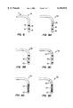
- FIG. 1A illustrates the tip of the catheter of FIG. 1 in which the proximal segment has a radius of curvature smaller than that of FIG. 1;
- FIG. 2 is a simplified view showing placement of the tip of the catheter of FIG. 1 within the inferior vena cava, right atrium and against the isthmus adjacent the tricuspid valve;
- FIGS. 3A and 3B are enlarged cross-sectional views of the tip of the catheter of FIG. 1 omitting the electrical conductor and thermocouple wires passing through the central lumen of the body of the catheter shaft;
- FIG. 3C is an enlarged side view of a segment of the catheter shaft of FIG. 1;
- FIGS. 3D-3F are cross-sectional views taken along lines 3D--3D through 3F--3F in FIG. 3A;
- FIGS. 3G and 3H are cross-sectional views taken along lines 3G--3G and 3H--3H in FIG. 3B;
- FIG. 3I is a cross-sectional view taken along line 3I--3I in FIG. 3C;
- FIG. 4 is a side view showing the tapered nature of the core wire
- FIGS. 6 and 7 are cross-sectional views of the polyimide tube and hypotube shown in FIG. 5;
- FIGS. 8A-8E are views similar to FIG. 8 of alternative embodiments of the distal segment of the tip of the catheter of FIG. 1;
- FIG. 10 is a schematic illustration showing the interconnections among the catheter of FIG. 1, a switchbox, an R.F. generator and an indifferent electrode.
- FIG. 1 illustrates an anatomically-conforming dual curve ablation catheter, in particular an atrial flutter ablation catheter 2, including a catheter shaft 4 having a distal end 6 and a proximal end 8.
- Proximal end 8 is mounted to a handle 10 having an axially slidable manipulator ring 12 and a rotatable lateral deflection ring 14 operably connected to a manipulator wire 16 and a core wire 18, respectively, shown in FIGS. 3A and 3D.
- Sliding manipulator ring 12 causes a deflectable tip 20 of catheter shaft 4 to deflect as shown in FIGS. 1 and 2 while rotating ring 14 causes lateral deflection of tip 20 through the torquing action of core wire 18.
- Insulator 44 has five bores or lumens which generally align with the corresponding lumens formed in shaft body 32.
- a cylindrical ablation electrode 48 is secured to and extends between insulator 44 and a second insulator 50.
- a tip electrode 68 is secured to the distal end of insulator 50.
- the connections between electrodes 48, 68 and insulators 44, 50 are preferably through both a snap fit and the use of adhesives or other bonding techniques.
- Tubular layer 38 terminates at a central bore in insulator 50 and is affixed thereto by adhesive.
- thermocouple wires 25 are not shown.
- High power electrical conductors 22, 23 are connected to ablation electrodes 48, 68 in conventional manners, such as soldering or welding.
- Pairs of thermocouple wires 24, 25 are respectively positioned adjacent ablation electrodes 68, 48 so to permit the temperatures of the ablation electrodes to be monitored.
- the hollow interior 78 of tip electrode 68 is filled with a thermally conducting but electrically insulating material, such as cyanoacrylate adhesive, so that thermocouple wires 24 positioned within interior 78 will be provided an accurate reading of the temperature of tip electrode 68, without electrical continuity between the two.
- thermocouple wires 25 and conductor 22 are positioned adjacent electrode 48 by elastically insulating materials 79, 81.
- Third segment 84 is a constant 0.018 inch diameter over a length of about 12-14 inches (30 to 36 cm). These first three segments 80, 82, 84 are all coated with PTFE to minimize friction within shaft 4.
- the fourth segment 86 core wire 18 tapers from 0.018 inch to 0.0085-0.0095 inch (0.46 mm to 0.22 to 0.24 mm) over a length of 1.5-2.5 inches (3.8 to 6.4 cm) while the final 5-inch (13 cm) length of core wire 18 is a constant diameter fifth segment 88, having a diameter of 0.0085-0.0095 inch.
- distal segment 30 is about 1.0-2.0 inches (2.54-5.08 cm) long
- intermediate segment 28 is about 1.4-2.2 inch (3.5 to 5.5 cm) long
- proximal segment 26 is about 0.8-1.6 inches (2.0-4.0 cm) long.
- hypotube 90 and polyimide tubes 92, 93 are shown only in FIGS. 3B, 3G and 5-7 for simplicity of illustration.
- the maximum angle for the primary curve at proximal segment 26 is about 120° and for the secondary curve at distal segment 30 is about 100°.
- FIG. 9 illustrates how the core wire design matches with the curve shape.
- shaft 4 and intermediate and distal segments 28 and 30 are made having different duometer hardnesses of about 65 D, 55 D and about 30-40 D, respectively.
- FIG. 2 illustrates, in simplified form, a portion of a heart 94 having a superior vena cava 96 and an inferior vena cava 98 opening into a right atrium 100. Also illustrated is a portion of right ventricle 102 separated from right atrium 100 by a tricuspid valve 104. An isthmus of tissue 106 extends between the inferior aspect of tricuspid valve 104 and inferior vena cava 98 adjacent the opening of the coronary sinus 108.
- Distal segment 30 is sized with an appropriate flexibility so that upon pulling of manipulator wire 16, distal segment 30 assumes the contour generally corresponding to the shape of the coronary tissue at isthmus 106 when oriented perpendicular to the isthmus of tissue 106.
- Intermediate segment 28 is sufficiently stiff, through the use of both hypotube 90 and polyimide tube 92, so that it remains substantially straight when distal segment 30 is properly flexed.
- Proximal segment 26 is less stiff than intermediate segment 28 but, in the preferred embodiment, stiffer than distal segment 30 but also has a curve which allows proximal segment 26 of shaft 4 to push against or be braced against the wall 110 of inferior vena cava 98. This stabilizes tip 20 of catheter 2 to help maintain distal segment 30 in the proper position at isthmus of tissue 106.
- ablation electrodes 48, 68 are positioned along isthmus of tissue 106. Once in position, electrodes 48, 68 can be coupled to a suitable RF power supply, not shown, through connector 21.
- a suitable RF power supply is shown in U.S. patent application Ser. No. 08/179,558, filed Jan. 10, 1994, the disclosure of which is incorporated by reference.
- Ablation electrodes 48, 68 are electrically isolated from one another so they can be independently powered from the power supply. This means that the power supply need not be as large as would be required if they were electrically connected to one another or if the separate ablation electrodes were replaced by a single, extra-long ablation electrode. This eliminates the need to move the ablation electrode after each application of power, the "burn-drag-burn" technique used with conventional ablation catheters.
- Ablation electrodes 48, 68 are powered one-at-a-time.
- a switchbox 130 is connected between the ablation catheter 2 and an RF generator 132. See FIG. 10.
- Switchbox 130 which can also be connected to an indifferent electrode 134, allows RF current to be directed to any available ablation electrodes.
- Thermocouple signals from the particular electrode, used for temperature control, are also supplied to switchbox 130. More than one ablation electrode and thermocouple can be connected simultaneously using switchbox 130. Switchbox 130 can also be automatically controlled.
- FIGS. 8-8E illustrate various configurations of ablation-capable and mapping electrodes which can be used.
- FIG. 8 shows ablation-capable electrodes 48, 68, each 4 mm long and having an outside diameter of 0.091 inch (2.3 mm), for catheter 2 of FIGS. 1-7.
- Distal segment 30a of the embodiment of FIG. 8A is like distal segment 30 of FIG. 8 but has two mapping band electrodes 120.
- FIG. 8B shows a distal segment 30b with two ablation-capable band electrodes 48 and a half-size (2 mm long) mapping tip electrode 122.
- Distal segment 30c of FIG. 8C adds two band mapping electrodes 120 to the embodiment of FIG. 8B.
- the embodiment of FIG. 8 shows ablation-capable electrodes 48, 68, each 4 mm long and having an outside diameter of 0.091 inch (2.3 mm), for catheter 2 of FIGS. 1-7.
- Distal segment 30a of the embodiment of FIG. 8A is like distal segment 30 of FIG. 8
- FIG. 8D shows the use of a spiral-wound or coiled ablation-capable electrode 124 adjacent to a mapping tip electrode while the FIG. 8E embodiment adds a pair of mapping band electrodes 120 to the FIG. 8D embodiment.
- Other electrode arrangements are also possible.
Abstract
A dual curve ablation catheter (2), especially suited for treating atrial flutter, includes a shaft (4) with a deflectable tip (20) at the distal end (6) and a handle (10) at the proximal end (8). The tip includes a highly flexible distal segment (30), a relatively stiff intermediate segment (28) and a flexible proximal segment (26) so that pulling on a manipulator wire (16) attached to the distal segment causes the distal segment to curve and engage, for example, an isthmus of tissue (106) adjacent the tricuspid valve (104) and the inferior vena cava (98) and causes the proximal segment to curve and press against the wall (110) of the inferior vena cava so to stabilize the catheter. Ablation energy can be supplied through the ablation electrodes (48, 68) simultaneously or one at a time to ablate tissue at the isthmus without the need for moving the catheter.
Description
This is a division of application Ser. No. 08/825,425, filed Mar. 28, 1997, now U.S. Pat. No. 5,916,214, which is a continuation of application Ser. No. 08/429,429, filed May 1, 1995, now abandoned, the disclosures of which are incorporated herein by reference.
It has long been known that the action of the heart depends upon electrical signals carried along the surface of the heart tissue. Sometimes these electrical signals become faulty. It has been found that ablating (burning) these cardiac conduction pathways in the region of the problem destroys the tissue to eliminate the faulty signal. Electrophysiology (EP) catheters are catheters having one or more electrodes at their tips and are used for both diagnosis and therapy. The electrodes at their tips of EP catheters allow the physician to measure electrical signals along the surface of the heart (called mapping) and then, when necessary, ablate certain tissue using, typically, radio frequency (RF) energy directed to one or more high energy capable ablation electrodes.
The present invention is directed to an EP ablation catheter especially suited for treating atrial flutter. Atrial flutter is a common rhythm disturbance defined as an atrial tachycardia with atrial rates exceeding 240 beats per minute. The invention creates a linear lesion oriented perpendicularly to the isthmus of tissue between the inferior aspect of the tricuspid valve and the inferior vena cava. The invention ablates a line of tissue across the critical isthmus using ablation-capable electrodes positioned along the tip of the catheter. The catheter is designed to remain in place and provide firm electrode contact during the ablation despite respiratory, cardiac or blood motion during the ablation.
The atrial flutter ablation catheter includes a shaft having proximal and distal ends with a deflectable tip at the distal end and a handle at the proximal end. The tip includes a highly flexible distal segment, a relatively stiff intermediate segment and a flexible proximal segment. Pulling on a manipulator wire, passing through a lumen in the shaft and attached to the distal end the shaft, causes the distal and proximal segments of the tip to curve. When properly positioned for treating atrial flutter, the distal segment engages the isthmus of tissue to be ablated, which lies adjacent the tricuspid valve and the inferior vena cava opening into the right atrium, and the proximal curve segment presses against the wall of the inferior vena cava so to stabilize the catheter. Ablation energy is supplied through the ablation electrodes, preferably one at a time, to ablate the tissue at the isthmus without the need for moving the catheter once in position.
A rotatable core wire, passing the central lumen and secured to the tip of the shaft, may be used to permit a torquing force to be applied to the distal end of the shaft without rotating the entire catheter. The temperature of the ablation electrodes is preferably monitored, such as using thermocouple wires, to permit enhanced control over the ablation temperatures.
One of the advantages of the invention is that it uses a series of ablation electrodes instead of one long electrode to ablate the cardiac tissue. Making the ablation electrodes electrically isolated from one another and allowing them to be individually powered permits a lower power ablation energy source to be used than would be required if the multiple ablation electrodes were replaced by one long electrode or if the multiple ablation electrodes were all powered simultaneously. Also, multiple electrodes allows bipolar recording to be conducted. Of course, if a power source has sufficient capacity to power more than one ablation electrode, this can be done also.
Other features and advantages of the invention will appear from the following description in which the preferred embodiment has been discussed in detail in conjunction with the accompanying drawings.
FIG. 1 is an overall view of an atrial flutter ablation catheter made according to the invention;
FIG. 1A illustrates the tip of the catheter of FIG. 1 in which the proximal segment has a radius of curvature smaller than that of FIG. 1;
FIG. 2 is a simplified view showing placement of the tip of the catheter of FIG. 1 within the inferior vena cava, right atrium and against the isthmus adjacent the tricuspid valve;
FIGS. 3A and 3B are enlarged cross-sectional views of the tip of the catheter of FIG. 1 omitting the electrical conductor and thermocouple wires passing through the central lumen of the body of the catheter shaft;
FIG. 3C is an enlarged side view of a segment of the catheter shaft of FIG. 1;
FIGS. 3D-3F are cross-sectional views taken along lines 3D--3D through 3F--3F in FIG. 3A;
FIGS. 3G and 3H are cross-sectional views taken along lines 3G--3G and 3H--3H in FIG. 3B;
FIG. 3I is a cross-sectional view taken along line 3I--3I in FIG. 3C;
FIG. 4 is a side view showing the tapered nature of the core wire;
FIG. 5 shows a core wire of FIG. 4 with a hypotube, shown in FIG. 7, and a polyimide tube shown in FIG. 6, strategically positioned along the length of the core wire to provide a very flexible distal segment, a moderately flexible proximal segment and a relatively stiff intermediate segment for the deflectable tip of the catheter of FIG. 1;
FIGS. 6 and 7 are cross-sectional views of the polyimide tube and hypotube shown in FIG. 5;
FIG. 8 is an enlarged view of the distal segment of the tip of the catheter of FIG. 1;
FIGS. 8A-8E are views similar to FIG. 8 of alternative embodiments of the distal segment of the tip of the catheter of FIG. 1;
FIG. 9 shows the distal portion of the assembly of FIG. 5 illustrating the positions of the proximal and distal curves relative to the positions of the various tubes mounted over the core wire; and
FIG. 10 is a schematic illustration showing the interconnections among the catheter of FIG. 1, a switchbox, an R.F. generator and an indifferent electrode.
FIG. 1 illustrates an anatomically-conforming dual curve ablation catheter, in particular an atrial flutter ablation catheter 2, including a catheter shaft 4 having a distal end 6 and a proximal end 8. Proximal end 8 is mounted to a handle 10 having an axially slidable manipulator ring 12 and a rotatable lateral deflection ring 14 operably connected to a manipulator wire 16 and a core wire 18, respectively, shown in FIGS. 3A and 3D. Sliding manipulator ring 12 causes a deflectable tip 20 of catheter shaft 4 to deflect as shown in FIGS. 1 and 2 while rotating ring 14 causes lateral deflection of tip 20 through the torquing action of core wire 18.
The portion of shaft 4 proximal of deflectable tip 20, see FIGS. 3C and 3I, is relatively stiff to permit controlled placement of tip 20 at the target site as discussed below. Such proximal portion of the shaft 4 includes an outer jacket 39, preferably made of higher durometer Pebax®, such as 55-65 D, reinforced by braided wires 41. A polyimide our ultem tubular layer 38a is positioned within the central lumen 34a and houses core wire 18, electrical connectors 22, 23, thermocouple wires 24,25 and manipulator wire 16.
If desired, one or more axially slidable core wires could be used with the distal ends of the core wires positionable at different axial positions along tip 20; doing so would permit the size of the curves of tip 20 to be changed. FIG. 1A illustrates the result of using such a slidable core wire. Tip 20a has a curve at proximal segment 26 with a larger radius than that if FIG. 1; the curves at distal segments 30 are the same for both figures. An example of a catheter with a variable curve tip is described in U.S. patent application Ser. No. 08/343,310 for Steerable Electrophysiology Catheter, the disclosure of which is incorporated by reference.
The distal end 42 of shaft body 32, see FIG. 3A, lies adjacent an insulator 44 made of PEEK (poly-ether-ether-keytone) or other hard, temperature-resistant material. Insulator 44 is bonded to distal end 42 of shaft body 32 by heat fusing and adhesive.
It should be noted that in FIGS. 3A and 3B electrical conductor 23 and thermocouple wires 25 are not shown. High power electrical conductors 22, 23 are connected to ablation electrodes 48, 68 in conventional manners, such as soldering or welding. Pairs of thermocouple wires 24, 25 are respectively positioned adjacent ablation electrodes 68, 48 so to permit the temperatures of the ablation electrodes to be monitored. The hollow interior 78 of tip electrode 68 is filled with a thermally conducting but electrically insulating material, such as cyanoacrylate adhesive, so that thermocouple wires 24 positioned within interior 78 will be provided an accurate reading of the temperature of tip electrode 68, without electrical continuity between the two. As shown in FIG. 3E, thermocouple wires 25 and conductor 22 are positioned adjacent electrode 48 by elastically insulating materials 79, 81.
Of the proximal, intermediate and distal segments 26, 28, 30, intermediate segment is the stiffest and distal segment 30 is the least stiff while proximal segment 26 has a stiffness somewhat between the two stiffnesses of segments 28, 30. To provide shaft 4 with these three different stiffness for tip 20, core wire 18 is modified to provide these stiffnesses. Core wire 18 is, in one preferred embodiment, about 60 inches (152 cm) long and has five distinct segments. Proximal segment 80 is about 35-39 inches (89 to 99 cm) long and has a diameter of about 0.025 inch (0.64 mm). A second segment 82 tapers in diameter from 0.025 inch to 0.018 inch (0.46 mm) over a distance of about 3 inches (7.6 cm). Third segment 84 is a constant 0.018 inch diameter over a length of about 12-14 inches (30 to 36 cm). These first three segments 80, 82, 84 are all coated with PTFE to minimize friction within shaft 4. The fourth segment 86 core wire 18 tapers from 0.018 inch to 0.0085-0.0095 inch (0.46 mm to 0.22 to 0.24 mm) over a length of 1.5-2.5 inches (3.8 to 6.4 cm) while the final 5-inch (13 cm) length of core wire 18 is a constant diameter fifth segment 88, having a diameter of 0.0085-0.0095 inch.
FIGS. 3B, 3G and 5 illustrate how the different stiffnesses for segments 26, 28 and 30 is achieved. A hypotube 90, made of stainless steel, is shown in cross-section in FIG. 7. Hypotube 90 has an inside diameter of 0.010-0.012 inch (0.25 to 0.30 mm) and an outside diameter of 0.018-0.022 inch (0.46 to 0.56 mm) and is used to cover core wire 18 over intermediate segment 28. Hypotube 90 extends for a distance of about 1.0-2.0 inch (2.5-5 cm) in a proximal direction along core wire 18 to ensure that the portion of tip 20 between sections 26 and 30 is relatively stiff. Polyimide tube 92 with an inside diameter of 0.0185-0.0225 inch (0.47 to 0.57 mm) and an outside diameter of 0.024-0.028 inch (0.61 to 0.71 mm) and a length of 0.25-0.5 inch (6.35-12.7 mm) is mounted over hypotube 90 within segment 30. A second polyimide tube 93 with the same I.D. and O.D. as polyimide tube 92 and a length of 1.0-1.5 inch (2.5-3.8 cm) fits over the extension of hypotube 90 within segment 26. In the preferred embodiment, distal segment 30 is about 1.0-2.0 inches (2.54-5.08 cm) long, intermediate segment 28 is about 1.4-2.2 inch (3.5 to 5.5 cm) long and proximal segment 26 is about 0.8-1.6 inches (2.0-4.0 cm) long. Note that hypotube 90 and polyimide tubes 92, 93 are shown only in FIGS. 3B, 3G and 5-7 for simplicity of illustration. The maximum angle for the primary curve at proximal segment 26 is about 120° and for the secondary curve at distal segment 30 is about 100°.
FIG. 9 illustrates how the core wire design matches with the curve shape. In addition to a core wire assembly with sections having different stiffnesses, shaft 4 and intermediate and distal segments 28 and 30 are made having different duometer hardnesses of about 65 D, 55 D and about 30-40 D, respectively.
The use of catheter 2 will be described in conjunction with FIG. 2. FIG. 2 illustrates, in simplified form, a portion of a heart 94 having a superior vena cava 96 and an inferior vena cava 98 opening into a right atrium 100. Also illustrated is a portion of right ventricle 102 separated from right atrium 100 by a tricuspid valve 104. An isthmus of tissue 106 extends between the inferior aspect of tricuspid valve 104 and inferior vena cava 98 adjacent the opening of the coronary sinus 108. Distal segment 30 is sized with an appropriate flexibility so that upon pulling of manipulator wire 16, distal segment 30 assumes the contour generally corresponding to the shape of the coronary tissue at isthmus 106 when oriented perpendicular to the isthmus of tissue 106. Intermediate segment 28 is sufficiently stiff, through the use of both hypotube 90 and polyimide tube 92, so that it remains substantially straight when distal segment 30 is properly flexed. Proximal segment 26 is less stiff than intermediate segment 28 but, in the preferred embodiment, stiffer than distal segment 30 but also has a curve which allows proximal segment 26 of shaft 4 to push against or be braced against the wall 110 of inferior vena cava 98. This stabilizes tip 20 of catheter 2 to help maintain distal segment 30 in the proper position at isthmus of tissue 106.
After any appropriate readings are taken, ablation electrodes 48, 68 are positioned along isthmus of tissue 106. Once in position, electrodes 48, 68 can be coupled to a suitable RF power supply, not shown, through connector 21. One such power supply is shown in U.S. patent application Ser. No. 08/179,558, filed Jan. 10, 1994, the disclosure of which is incorporated by reference. Ablation electrodes 48, 68 are electrically isolated from one another so they can be independently powered from the power supply. This means that the power supply need not be as large as would be required if they were electrically connected to one another or if the separate ablation electrodes were replaced by a single, extra-long ablation electrode. This eliminates the need to move the ablation electrode after each application of power, the "burn-drag-burn" technique used with conventional ablation catheters. Ablation electrodes 48, 68 are powered one-at-a-time.
Typically, a switchbox 130 is connected between the ablation catheter 2 and an RF generator 132. See FIG. 10. Switchbox 130, which can also be connected to an indifferent electrode 134, allows RF current to be directed to any available ablation electrodes. Thermocouple signals from the particular electrode, used for temperature control, are also supplied to switchbox 130. More than one ablation electrode and thermocouple can be connected simultaneously using switchbox 130. Switchbox 130 can also be automatically controlled.
FIGS. 8-8E illustrate various configurations of ablation-capable and mapping electrodes which can be used. FIG. 8 shows ablation- capable electrodes 48, 68, each 4 mm long and having an outside diameter of 0.091 inch (2.3 mm), for catheter 2 of FIGS. 1-7. Distal segment 30a of the embodiment of FIG. 8A is like distal segment 30 of FIG. 8 but has two mapping band electrodes 120. FIG. 8B shows a distal segment 30b with two ablation-capable band electrodes 48 and a half-size (2 mm long) mapping tip electrode 122. Distal segment 30c of FIG. 8C adds two band mapping electrodes 120 to the embodiment of FIG. 8B. The embodiment of FIG. 8D shows the use of a spiral-wound or coiled ablation-capable electrode 124 adjacent to a mapping tip electrode while the FIG. 8E embodiment adds a pair of mapping band electrodes 120 to the FIG. 8D embodiment. Other electrode arrangements are also possible.
Modification and variation can be made to the disclosed embodiment without departing from the subject of the invention as defined in the following claims. For example, materials, diameters and lengths can be changed to suit the particular needs or desires of the user. The attachment and bonding techniques discussed above are merely exemplary; other chemical, mechanical and/or thermal bonding techniques can be used as well. In some cases it may be desired to apply energy to more than one ablation electrode at the same time; for example, four ablation electrodes could be used and powered two-at-a-time. The portion of distal segment 30 carrying ablation-capable electrodes 48 could be made to be curved or curvable if desired. While the invention has its greatest utility as an atrial flutter ablation catheter, it may also find use in ablating tissue at the mitral valve, in addition to tricuspid valve 104, and accessory pathways in the postero-lateral right ventricle. Other curve sizes and spacings for this dual curve catheter could also make it suitable for mapping and ablating other areas of the heart.
Claims (25)
1. A method for ablation of heart tissue at a target site comprising the following steps:
passing a distal segment of an ablation catheter into a chamber of a heart;
manipulating the distal segment of the ablation catheter to the target site;
curving said distal segment as necessary to generally conform to any curvature of the target site;
placing the curved distal segment against the target site;
bracing a second segment of the ablation catheter near the target site;
applying ablation energy to an ablation electrode at the distal segment to ablate heart tissue at the target site; and
maintaining at least a portion of said distal segment substantially in position against the target site during the ablation energy applying step.
2. The method according to claim 1 wherein the target site is an isthmus of tissue adjacent a tricuspid valve in an inferior vena cava.
3. The method according to claim 1 wherein the ablation energy applying step is carried out by sequentially applying ablation energy to a plurality of electrically isolated ablation electrodes spaced apart along at least the distal segment to ablate heart tissue at an isthmus of tissue.
4. The method according to claim 1 wherein the ablation energy applying step is carried out by simultaneously applying ablation energy to at least two ablation electrodes.
5. The method according to claim 1 wherein the manipulating step includes the steps of selectively applying a torquing force to said distal segment thereby causing said distal segment, when curved, to move laterally.
6. The method according to claim 1 wherein the curving step is carried out by pulling on a manipulator wire connected to said distal segment and passing through a lumen in the ablation catheter.
7. The method according to claim 1 wherein bracing a second segment of the ablation catheter includes bracing the second segment against a wall of an inferior vena cava.
8. The method according to claim 7 wherein the bracing step is carried out by pulling on a manipulator wire passing through a lumen in the ablation catheter.
9. The method according to claim 7 wherein the curving and bracing steps are carried out by pulling on a manipulator wire passing through a lumen in the ablation catheter.
10. The method according to claim 7 further comprising the step of providing a tubular ablation catheter shaft having an intermediate segment between the distal and second segments and an axially movable manipulator wire extending through a lumen in the tubular ablation catheter shaft and secured to said distal segment, the intermediate segment being substantially stiffer than the second segment and the second segment being at least as stiff as the distal segment, the curving step being carried out by pulling on the manipulator wire thereby curving the distal and second segments while the intermediate segment remains substantially straight.
11. The method according to claim 1 further comprising the step of monitoring a temperature of said ablation electrode.
12. The method according to claim 1 further comprising the step of electrically mapping an area of the heart at or near an isthmus of tissue.
13. The method according to claim 12 wherein the mapping step is carried out using at least one mapping electrode mounted to the ablation catheter proximal of said ablation electrode.
14. The method according to claim 13 wherein the mapping step is carried out using at least one mapping electrode distal of said ablation electrode.
15. The method according to claim 1 wherein bracing the second segment includes positioning the second segment against tissue proximate the target site.
16. The method according to claim 1 further comprising the step of completing ablation of the target site.
17. The method according to claim 16 wherein the target site is an isthmus of tissue.
18. The method according to claim 16 wherein completing target site ablation includes ablating a plurality of tissue locations.
19. The method according to claim 18 wherein the step of ablating a plurality of tissue locations occurs without movement of the distal segment.
20. A method for treating atrial flutter through ablation of heart tissue comprising the following steps:
passing a distal segment of an ablation catheter through an inferior vena cava and into a right atrium of a heart;
manipulating the distal segment of the ablation catheter to an isthmus of tissue adjacent a tricuspid valve and the inferior vena cava;
curving said distal segment to generally conform to the curvature of the isthmus of tissue;
placing the curved distal segment against the isthmus of tissue;
bracing a second segment of the ablation catheter against a wall of the inferior vena cava;
applying ablation energy to an ablation electrode at the distal segment to ablate heart tissue at the isthmus of tissue; and
maintaining at least a portion of said distal segment substantially in position against the isthmus of tissue during the ablation energy applying step.
21. A method for treating atrial flutter through ablation of heart tissue comprising the following steps:
passing a distal segment of an ablation catheter through an inferior vena cava and into a right atrium of a heart;
manipulating the distal segment of the ablation catheter to an isthmus of tissue adjacent a tricuspid valve and the inferior vena cava;
electrically mapping an area of the heart at or near the isthmus of tissue using at least one mapping electrode mounted to the ablation catheter;
curving said distal segment to generally conform to the curvature of the isthmus of tissue;
placing the curved distal segment against the isthmus of tissue;
bracing a second segment of the ablation catheter against a wall of the inferior vena cava;
sequentially applying ablation energy to electrically isolated ablation electrodes spaced apart along at least the distal segment to ablate heart tissue at the isthmus of tissue;
monitoring the temperature of at least one of said ablation electrodes; and
maintaining at least a portion of said distal segment substantially in position against the isthmus of tissue during the ablation energy applying step.
22. A method for the ablation of heart tissue at a target site comprising the following steps:
passing a distal segment of a catheter having a plurality of ablation electrodes on the distal segment into the right atrium of a heart;
manipulating the distal segment of the catheter to an isthmus of tissue between an inferior aspect of a tricuspid valve and an inferior vena cava;
curving the distal segment to generally conform to the curvature of the isthmus of tissue;
placing the curved distal segment against the isthmus of tissue; and
applying ablation energy to the plurality of electrodes such that the isthmus of tissue is ablated without moving the curved distal segment.
23. The method according to claim 22 wherein ablation energy is applied by sequentially applying ablation energy to the plurality of ablation electrodes.
24. The method according to claim 22 wherein ablation energy is applied simultaneously to at least two ablation electrodes.
25. The method according to claim 22 wherein the ablation energy applied to ablate the isthmus of tissue is sufficient to treat atrial flutter in the patient.
Priority Applications (1)
| Application Number | Priority Date | Filing Date | Title |
|---|---|---|---|
| US09/218,769 US6156034A (en) | 1995-05-01 | 1998-12-22 | Method for ablation of heart tissue |
Applications Claiming Priority (3)
| Application Number | Priority Date | Filing Date | Title |
|---|---|---|---|
| US42942995A | 1995-05-01 | 1995-05-01 | |
| US08/825,425 US5916214A (en) | 1995-05-01 | 1997-03-28 | Dual curve ablation catheter |
| US09/218,769 US6156034A (en) | 1995-05-01 | 1998-12-22 | Method for ablation of heart tissue |
Related Parent Applications (1)
| Application Number | Title | Priority Date | Filing Date |
|---|---|---|---|
| US08/825,425 Continuation US5916214A (en) | 1995-05-01 | 1997-03-28 | Dual curve ablation catheter |
Publications (1)
| Publication Number | Publication Date |
|---|---|
| US6156034A true US6156034A (en) | 2000-12-05 |
Family
ID=23703211
Family Applications (2)
| Application Number | Title | Priority Date | Filing Date |
|---|---|---|---|
| US08/825,425 Expired - Lifetime US5916214A (en) | 1995-05-01 | 1997-03-28 | Dual curve ablation catheter |
| US09/218,769 Expired - Lifetime US6156034A (en) | 1995-05-01 | 1998-12-22 | Method for ablation of heart tissue |
Family Applications Before (1)
| Application Number | Title | Priority Date | Filing Date |
|---|---|---|---|
| US08/825,425 Expired - Lifetime US5916214A (en) | 1995-05-01 | 1997-03-28 | Dual curve ablation catheter |
Country Status (3)
| Country | Link |
|---|---|
| US (2) | US5916214A (en) |
| AU (1) | AU5558096A (en) |
| WO (1) | WO1996034646A1 (en) |
Cited By (17)
| Publication number | Priority date | Publication date | Assignee | Title |
|---|---|---|---|---|
| US20050004516A1 (en) * | 2003-07-02 | 2005-01-06 | Guy Vanney | Steerable and shapable catheter employing fluid force |
| US20070016164A1 (en) * | 2005-06-28 | 2007-01-18 | Dudney Joshua L | Actuation handle for a catheter |
| US20080139999A1 (en) * | 2004-05-17 | 2008-06-12 | C.R. Bard, Inc. | Articulated Catheter |
| US7591784B2 (en) | 2005-04-26 | 2009-09-22 | St. Jude Medical, Atrial Fibrillation Division, Inc. | Bi-directional handle for a catheter |
| US7691095B2 (en) | 2004-12-28 | 2010-04-06 | St. Jude Medical, Atrial Fibrillation Division, Inc. | Bi-directional steerable catheter control handle |
| US20100179629A1 (en) * | 2007-06-28 | 2010-07-15 | Rolf Hill | Medical implantable lead and method for manufacturing the same |
| US7819868B2 (en) | 2005-06-21 | 2010-10-26 | St. Jude Medical, Atrial Fibrilation Division, Inc. | Ablation catheter with fluid distribution structures |
| US7819866B2 (en) | 2003-01-21 | 2010-10-26 | St. Jude Medical, Atrial Fibrillation Division, Inc. | Ablation catheter and electrode |
| US8273285B2 (en) | 2005-01-10 | 2012-09-25 | St. Jude Medical, Atrial Fibrillation Division, Inc. | Steerable catheter and methods of making the same |
| US8372033B2 (en) | 2008-12-31 | 2013-02-12 | St. Jude Medical, Atrial Fibrillation Division, Inc. | Catheter having proximal heat sensitive deflection mechanism and related methods of use and manufacturing |
| US8583260B2 (en) | 2004-12-28 | 2013-11-12 | St. Jude Medical, Atrial Fibrillation Division, Inc. | Long travel steerable catheter actuator |
| US8777929B2 (en) | 2005-06-28 | 2014-07-15 | St. Jude Medical, Atrial Fibrillation Division, Inc. | Auto lock for catheter handle |
| US9795765B2 (en) | 2010-04-09 | 2017-10-24 | St. Jude Medical International Holding S.À R.L. | Variable stiffness steering mechanism for catheters |
| US9855404B2 (en) | 2013-05-03 | 2018-01-02 | St. Jude Medical International Holding S.À R.L. | Dual bend radii steering catheter |
| US20180078772A1 (en) * | 2016-09-16 | 2018-03-22 | Terrell M. Williams | Permanent His-Bundle Pacing Device and Method |
| US10183149B2 (en) | 2004-12-28 | 2019-01-22 | St. Jude Medical, Atrial Fibrillation Division, Inc. | Five degree of freedom ultrasound catheter and catheter control handle |
| US11648053B2 (en) | 2018-12-20 | 2023-05-16 | Biosense Webster (Israel) Ltd. | Catheter with flex circuit distal assembly |
Families Citing this family (200)
| Publication number | Priority date | Publication date | Assignee | Title |
|---|---|---|---|---|
| US6277112B1 (en) | 1996-07-16 | 2001-08-21 | Arthrocare Corporation | Methods for electrosurgical spine surgery |
| US6161543A (en) | 1993-02-22 | 2000-12-19 | Epicor, Inc. | Methods of epicardial ablation for creating a lesion around the pulmonary veins |
| US6409722B1 (en) | 1998-07-07 | 2002-06-25 | Medtronic, Inc. | Apparatus and method for creating, maintaining, and controlling a virtual electrode used for the ablation of tissue |
| US5897553A (en) | 1995-11-02 | 1999-04-27 | Medtronic, Inc. | Ball point fluid-assisted electrocautery device |
| DE29519651U1 (en) * | 1995-12-14 | 1996-02-01 | Muntermann Axel | Device for linear radio frequency catheter ablation of endomyocardial tissue |
| US6719755B2 (en) | 1996-10-22 | 2004-04-13 | Epicor Medical, Inc. | Methods and devices for ablation |
| US6237605B1 (en) | 1996-10-22 | 2001-05-29 | Epicor, Inc. | Methods of epicardial ablation |
| US7052493B2 (en) | 1996-10-22 | 2006-05-30 | Epicor Medical, Inc. | Methods and devices for ablation |
| US6311692B1 (en) | 1996-10-22 | 2001-11-06 | Epicor, Inc. | Apparatus and method for diagnosis and therapy of electrophysiological disease |
| US6805128B1 (en) | 1996-10-22 | 2004-10-19 | Epicor Medical, Inc. | Apparatus and method for ablating tissue |
| US6840936B2 (en) * | 1996-10-22 | 2005-01-11 | Epicor Medical, Inc. | Methods and devices for ablation |
| US5779669A (en) * | 1996-10-28 | 1998-07-14 | C. R. Bard, Inc. | Steerable catheter with fixed curve |
| US6051008A (en) | 1996-12-02 | 2000-04-18 | Angiotrax, Inc. | Apparatus having stabilization members for percutaneously performing surgery and methods of use |
| US6120520A (en) | 1997-05-27 | 2000-09-19 | Angiotrax, Inc. | Apparatus and methods for stimulating revascularization and/or tissue growth |
| US6102926A (en) | 1996-12-02 | 2000-08-15 | Angiotrax, Inc. | Apparatus for percutaneously performing myocardial revascularization having means for sensing tissue parameters and methods of use |
| AU6165898A (en) * | 1997-02-12 | 1998-08-26 | Oratec Interventions, Inc. | Method and apparatus for the treatment of strabismus |
| US6226554B1 (en) * | 1997-06-02 | 2001-05-01 | Hosheng Tu | Catheter system having a ball electrode and methods thereof |
| US6096037A (en) | 1997-07-29 | 2000-08-01 | Medtronic, Inc. | Tissue sealing electrosurgery device and methods of sealing tissue |
| EP0904795A1 (en) * | 1997-09-05 | 1999-03-31 | Cordis Webster, Inc. | Thin-walled catheter with high torsional stiffness |
| US8709007B2 (en) | 1997-10-15 | 2014-04-29 | St. Jude Medical, Atrial Fibrillation Division, Inc. | Devices and methods for ablating cardiac tissue |
| US6212434B1 (en) | 1998-07-22 | 2001-04-03 | Cardiac Pacemakers, Inc. | Single pass lead system |
| US6527767B2 (en) * | 1998-05-20 | 2003-03-04 | New England Medical Center | Cardiac ablation system and method for treatment of cardiac arrhythmias and transmyocardial revascularization |
| US6537248B2 (en) | 1998-07-07 | 2003-03-25 | Medtronic, Inc. | Helical needle apparatus for creating a virtual electrode used for the ablation of tissue |
| US6706039B2 (en) | 1998-07-07 | 2004-03-16 | Medtronic, Inc. | Method and apparatus for creating a bi-polar virtual electrode used for the ablation of tissue |
| US6501990B1 (en) | 1999-12-23 | 2002-12-31 | Cardiac Pacemakers, Inc. | Extendable and retractable lead having a snap-fit terminal connector |
| US6463334B1 (en) * | 1998-11-02 | 2002-10-08 | Cardiac Pacemakers, Inc. | Extendable and retractable lead |
| US8308719B2 (en) | 1998-09-21 | 2012-11-13 | St. Jude Medical, Atrial Fibrillation Division, Inc. | Apparatus and method for ablating tissue |
| US6572611B1 (en) * | 1998-11-23 | 2003-06-03 | C. R. Bard, Inc. | Intracardiac grasp catheter |
| US6638278B2 (en) * | 1998-11-23 | 2003-10-28 | C. R. Bard, Inc. | Intracardiac grasp catheter |
| US6319250B1 (en) * | 1998-11-23 | 2001-11-20 | C.R. Bard, Inc | Tricuspid annular grasp catheter |
| GB2347084B (en) * | 1999-02-26 | 2003-02-12 | Medtronic Inc | Ablation lead for atrial flutter |
| US8285393B2 (en) * | 1999-04-16 | 2012-10-09 | Laufer Michael D | Device for shaping infarcted heart tissue and method of using the device |
| US6577902B1 (en) * | 1999-04-16 | 2003-06-10 | Tony R. Brown | Device for shaping infarcted heart tissue and method of using the device |
| US9033961B2 (en) | 1999-07-14 | 2015-05-19 | Cardiofocus, Inc. | Cardiac ablation catheters for forming overlapping lesions |
| US8900219B2 (en) | 1999-07-14 | 2014-12-02 | Cardiofocus, Inc. | System and method for visualizing tissue during ablation procedures |
| US8540704B2 (en) | 1999-07-14 | 2013-09-24 | Cardiofocus, Inc. | Guided cardiac ablation catheters |
| EP1207788A4 (en) | 1999-07-19 | 2009-12-09 | St Jude Medical Atrial Fibrill | Apparatus and method for ablating tissue |
| US6332881B1 (en) | 1999-09-01 | 2001-12-25 | Cardima, Inc. | Surgical ablation tool |
| WO2001043653A1 (en) * | 1999-12-15 | 2001-06-21 | Edwards Stuart D | Treatment of eustachian tube dysfunction by application of radiofrequency energy |
| US7706882B2 (en) | 2000-01-19 | 2010-04-27 | Medtronic, Inc. | Methods of using high intensity focused ultrasound to form an ablated tissue area |
| US8221402B2 (en) | 2000-01-19 | 2012-07-17 | Medtronic, Inc. | Method for guiding a medical device |
| US8241274B2 (en) | 2000-01-19 | 2012-08-14 | Medtronic, Inc. | Method for guiding a medical device |
| US8048070B2 (en) | 2000-03-06 | 2011-11-01 | Salient Surgical Technologies, Inc. | Fluid-assisted medical devices, systems and methods |
| US8083736B2 (en) | 2000-03-06 | 2011-12-27 | Salient Surgical Technologies, Inc. | Fluid-assisted medical devices, systems and methods |
| US6638268B2 (en) | 2000-04-07 | 2003-10-28 | Imran K. Niazi | Catheter to cannulate the coronary sinus |
| EP1278471B1 (en) | 2000-04-27 | 2005-06-15 | Medtronic, Inc. | Vibration sensitive ablation apparatus |
| US6558382B2 (en) * | 2000-04-27 | 2003-05-06 | Medtronic, Inc. | Suction stabilized epicardial ablation devices |
| US6514250B1 (en) | 2000-04-27 | 2003-02-04 | Medtronic, Inc. | Suction stabilized epicardial ablation devices |
| AU2001273421A1 (en) | 2000-07-13 | 2002-01-30 | Bioheart, Inc. | Deployment system for myocardial cellular material |
| US6746446B1 (en) | 2000-08-04 | 2004-06-08 | Cardima, Inc. | Electrophysiological device for the isthmus |
| US7070596B1 (en) * | 2000-08-09 | 2006-07-04 | Arthrocare Corporation | Electrosurgical apparatus having a curved distal section |
| US6482221B1 (en) * | 2000-08-21 | 2002-11-19 | Counter Clockwise, Inc. | Manipulatable delivery catheter for occlusive devices (II) |
| US6726700B1 (en) | 2000-08-21 | 2004-04-27 | Counter Clockwise, Inc. | Manipulatable delivery catheter for occlusive devices |
| US6926669B1 (en) * | 2000-10-10 | 2005-08-09 | Medtronic, Inc. | Heart wall ablation/mapping catheter and method |
| US7740623B2 (en) | 2001-01-13 | 2010-06-22 | Medtronic, Inc. | Devices and methods for interstitial injection of biologic agents into tissue |
| US20040138621A1 (en) | 2003-01-14 | 2004-07-15 | Jahns Scott E. | Devices and methods for interstitial injection of biologic agents into tissue |
| US6740040B1 (en) | 2001-01-30 | 2004-05-25 | Advanced Cardiovascular Systems, Inc. | Ultrasound energy driven intraventricular catheter to treat ischemia |
| US7959626B2 (en) | 2001-04-26 | 2011-06-14 | Medtronic, Inc. | Transmural ablation systems and methods |
| US6663627B2 (en) | 2001-04-26 | 2003-12-16 | Medtronic, Inc. | Ablation system and method of use |
| US6699240B2 (en) | 2001-04-26 | 2004-03-02 | Medtronic, Inc. | Method and apparatus for tissue ablation |
| US6807968B2 (en) | 2001-04-26 | 2004-10-26 | Medtronic, Inc. | Method and system for treatment of atrial tachyarrhythmias |
| US6979342B2 (en) | 2001-09-19 | 2005-12-27 | Advanced Cardiovascular Systems, Incc | Catheter with a polyimide distal tip |
| US6863678B2 (en) | 2001-09-19 | 2005-03-08 | Advanced Cardiovascular Systems, Inc. | Catheter with a multilayered shaft section having a polyimide layer |
| US7967816B2 (en) | 2002-01-25 | 2011-06-28 | Medtronic, Inc. | Fluid-assisted electrosurgical instrument with shapeable electrode |
| US7653438B2 (en) | 2002-04-08 | 2010-01-26 | Ardian, Inc. | Methods and apparatus for renal neuromodulation |
| US8774913B2 (en) | 2002-04-08 | 2014-07-08 | Medtronic Ardian Luxembourg S.A.R.L. | Methods and apparatus for intravasculary-induced neuromodulation |
| US8150519B2 (en) | 2002-04-08 | 2012-04-03 | Ardian, Inc. | Methods and apparatus for bilateral renal neuromodulation |
| US7294143B2 (en) | 2002-05-16 | 2007-11-13 | Medtronic, Inc. | Device and method for ablation of cardiac tissue |
| US7118566B2 (en) | 2002-05-16 | 2006-10-10 | Medtronic, Inc. | Device and method for needle-less interstitial injection of fluid for ablation of cardiac tissue |
| US7033345B2 (en) * | 2002-05-21 | 2006-04-25 | Advanced Cardiovascular Systems, Inc. | Deflectable microimplant delivery system |
| US7258690B2 (en) | 2003-03-28 | 2007-08-21 | Relievant Medsystems, Inc. | Windowed thermal ablation probe |
| US6907884B2 (en) | 2002-09-30 | 2005-06-21 | Depay Acromed, Inc. | Method of straddling an intraosseous nerve |
| US8361067B2 (en) | 2002-09-30 | 2013-01-29 | Relievant Medsystems, Inc. | Methods of therapeutically heating a vertebral body to treat back pain |
| US20050033137A1 (en) * | 2002-10-25 | 2005-02-10 | The Regents Of The University Of Michigan | Ablation catheters and methods for their use |
| US20040082947A1 (en) | 2002-10-25 | 2004-04-29 | The Regents Of The University Of Michigan | Ablation catheters |
| US7083620B2 (en) | 2002-10-30 | 2006-08-01 | Medtronic, Inc. | Electrosurgical hemostat |
| US7497857B2 (en) | 2003-04-29 | 2009-03-03 | Medtronic, Inc. | Endocardial dispersive electrode for use with a monopolar RF ablation pen |
| US7794456B2 (en) | 2003-05-13 | 2010-09-14 | Arthrocare Corporation | Systems and methods for electrosurgical intervertebral disc replacement |
| US8308708B2 (en) | 2003-07-15 | 2012-11-13 | Abbott Cardiovascular Systems Inc. | Deployment system for myocardial cellular material |
| WO2005039390A2 (en) | 2003-10-20 | 2005-05-06 | Arthrocare Corporation | Electrosurgical method and apparatus for removing tissue within a bone body |
| US7245973B2 (en) | 2003-12-23 | 2007-07-17 | Cardiac Pacemakers, Inc. | His bundle mapping, pacing, and injection lead |
| US8333764B2 (en) | 2004-05-12 | 2012-12-18 | Medtronic, Inc. | Device and method for determining tissue thickness and creating cardiac ablation lesions |
| US20060009756A1 (en) | 2004-05-14 | 2006-01-12 | Francischelli David E | Method and devices for treating atrial fibrillation by mass ablation |
| US20050273096A1 (en) * | 2004-05-27 | 2005-12-08 | Roop John A | Anchoring introducer sheath with distal slots for catheter delivery and translation |
| US7250049B2 (en) * | 2004-05-27 | 2007-07-31 | St. Jude Medical, Atrial Fibrillation Division, Inc. | Ablation catheter with suspension system incorporating rigid and flexible components |
| US7122034B2 (en) * | 2004-05-27 | 2006-10-17 | St. Jude Medical, Atrial Fibrillation Division, Inc. | Curved ablation catheter |
| ATE516762T1 (en) | 2004-06-02 | 2011-08-15 | Medtronic Inc | ABLATION AND STAPLE INSTRUMENT |
| WO2005120374A1 (en) | 2004-06-02 | 2005-12-22 | Medtronic, Inc. | Compound bipolar ablation device and method |
| WO2005120376A2 (en) | 2004-06-02 | 2005-12-22 | Medtronic, Inc. | Ablation device with jaws |
| WO2005120375A2 (en) | 2004-06-02 | 2005-12-22 | Medtronic, Inc. | Loop ablation apparatus and method |
| US8409219B2 (en) | 2004-06-18 | 2013-04-02 | Medtronic, Inc. | Method and system for placement of electrical lead inside heart |
| US8663245B2 (en) | 2004-06-18 | 2014-03-04 | Medtronic, Inc. | Device for occlusion of a left atrial appendage |
| US8926635B2 (en) | 2004-06-18 | 2015-01-06 | Medtronic, Inc. | Methods and devices for occlusion of an atrial appendage |
| WO2006002337A2 (en) | 2004-06-24 | 2006-01-05 | Arthrocare Corporation | Electrosurgical device having planar vertical electrode and related methods |
| US7717875B2 (en) * | 2004-07-20 | 2010-05-18 | St. Jude Medical, Atrial Fibrillation Division, Inc. | Steerable catheter with hydraulic or pneumatic actuator |
| US20060089637A1 (en) | 2004-10-14 | 2006-04-27 | Werneth Randell L | Ablation catheter |
| US8409191B2 (en) * | 2004-11-04 | 2013-04-02 | Boston Scientific Scimed, Inc. | Preshaped ablation catheter for ablating pulmonary vein ostia within the heart |
| US8617152B2 (en) | 2004-11-15 | 2013-12-31 | Medtronic Ablation Frontiers Llc | Ablation system with feedback |
| US7468062B2 (en) | 2004-11-24 | 2008-12-23 | Ablation Frontiers, Inc. | Atrial ablation catheter adapted for treatment of septal wall arrhythmogenic foci and method of use |
| US7429261B2 (en) | 2004-11-24 | 2008-09-30 | Ablation Frontiers, Inc. | Atrial ablation catheter and method of use |
| US8005544B2 (en) | 2004-12-20 | 2011-08-23 | Cardiac Pacemakers, Inc. | Endocardial pacing devices and methods useful for resynchronization and defibrillation |
| US8290586B2 (en) | 2004-12-20 | 2012-10-16 | Cardiac Pacemakers, Inc. | Methods, devices and systems for single-chamber pacing using a dual-chamber pacing device |
| US8326423B2 (en) | 2004-12-20 | 2012-12-04 | Cardiac Pacemakers, Inc. | Devices and methods for steering electrical stimulation in cardiac rhythm management |
| US8010192B2 (en) | 2004-12-20 | 2011-08-30 | Cardiac Pacemakers, Inc. | Endocardial pacing relating to conduction abnormalities |
| US8423139B2 (en) | 2004-12-20 | 2013-04-16 | Cardiac Pacemakers, Inc. | Methods, devices and systems for cardiac rhythm management using an electrode arrangement |
| AR047851A1 (en) | 2004-12-20 | 2006-03-01 | Giniger Alberto German | A NEW MARCAPASOS THAT RESTORES OR PRESERVES THE PHYSIOLOGICAL ELECTRIC DRIVING OF THE HEART AND A METHOD OF APPLICATION |
| US8010191B2 (en) | 2004-12-20 | 2011-08-30 | Cardiac Pacemakers, Inc. | Systems, devices and methods for monitoring efficiency of pacing |
| US7455670B2 (en) * | 2005-01-14 | 2008-11-25 | Co-Repair, Inc. | System and method for the treatment of heart tissue |
| US20070156210A1 (en) * | 2005-01-14 | 2007-07-05 | Co-Repair, Inc., A California Corporation | Method for the treatment of heart tissue |
| US9320564B2 (en) * | 2005-05-05 | 2016-04-26 | Boston Scientific Scimed Inc. | Steerable catheter and method for performing medical procedure adjacent pulmonary vein ostia |
| US8932208B2 (en) | 2005-05-26 | 2015-01-13 | Maquet Cardiovascular Llc | Apparatus and methods for performing minimally-invasive surgical procedures |
| JP2009500052A (en) | 2005-06-20 | 2009-01-08 | アブレーション フロンティアズ,インコーポレーテッド | Ablation catheter |
| AU2006268238A1 (en) | 2005-07-11 | 2007-01-18 | Medtronic Ablation Frontiers Llc | Low power tissue ablation system |
| US8657814B2 (en) | 2005-08-22 | 2014-02-25 | Medtronic Ablation Frontiers Llc | User interface for tissue ablation system |
| US7623899B2 (en) * | 2005-09-16 | 2009-11-24 | Biosense Webster, Inc. | Catheter with flexible pre-shaped tip section |
| US7879034B2 (en) | 2006-03-02 | 2011-02-01 | Arthrocare Corporation | Internally located return electrode electrosurgical apparatus, system and method |
| WO2007136853A2 (en) | 2006-05-20 | 2007-11-29 | Darrell Hartwick | Medical device using beam construction and methods |
| US20080039746A1 (en) | 2006-05-25 | 2008-02-14 | Medtronic, Inc. | Methods of using high intensity focused ultrasound to form an ablated tissue area containing a plurality of lesions |
| US8382738B2 (en) | 2006-06-30 | 2013-02-26 | Abbott Cardiovascular Systems, Inc. | Balloon catheter tapered shaft having high strength and flexibility and method of making same |
| US10624621B2 (en) | 2006-11-07 | 2020-04-21 | Corvia Medical, Inc. | Devices and methods for the treatment of heart failure |
| US20110257723A1 (en) | 2006-11-07 | 2011-10-20 | Dc Devices, Inc. | Devices and methods for coronary sinus pressure relief |
| US8641704B2 (en) | 2007-05-11 | 2014-02-04 | Medtronic Ablation Frontiers Llc | Ablation therapy system and method for treating continuous atrial fibrillation |
| US20090082756A1 (en) * | 2007-09-25 | 2009-03-26 | Vasundhara Vidyarthi | Transradial coronary catheter |
| EP2209517A4 (en) | 2007-10-05 | 2011-03-30 | Maquet Cardiovascular Llc | Devices and methods for minimally-invasive surgical procedures |
| US8403885B2 (en) | 2007-12-17 | 2013-03-26 | Abbott Cardiovascular Systems Inc. | Catheter having transitioning shaft segments |
| EP2227174B1 (en) | 2007-12-28 | 2019-05-01 | Salient Surgical Technologies, Inc. | Fluid-assisted electrosurgical device |
| US8821488B2 (en) | 2008-05-13 | 2014-09-02 | Medtronic, Inc. | Tissue lesion evaluation |
| US10028753B2 (en) | 2008-09-26 | 2018-07-24 | Relievant Medsystems, Inc. | Spine treatment kits |
| EP3406210A1 (en) | 2008-09-26 | 2018-11-28 | Relievant Medsystems, Inc. | Systems and for navigating an instrument through bone |
| US8052638B2 (en) | 2008-11-26 | 2011-11-08 | Abbott Cardiovascular Systems, Inc. | Robust multi-layer balloon |
| US8444608B2 (en) | 2008-11-26 | 2013-05-21 | Abbott Cardivascular Systems, Inc. | Robust catheter tubing |
| EP2384222A2 (en) | 2008-12-19 | 2011-11-09 | Cardiac Pacemakers, Inc. | Devices, methods, and systems including cardiac pacing |
| US8652129B2 (en) | 2008-12-31 | 2014-02-18 | Medtronic Ardian Luxembourg S.A.R.L. | Apparatus, systems, and methods for achieving intravascular, thermally-induced renal neuromodulation |
| US20100168739A1 (en) * | 2008-12-31 | 2010-07-01 | Ardian, Inc. | Apparatus, systems, and methods for achieving intravascular, thermally-induced renal neuromodulation |
| US9254168B2 (en) | 2009-02-02 | 2016-02-09 | Medtronic Advanced Energy Llc | Electro-thermotherapy of tissue using penetrating microelectrode array |
| JP5592409B2 (en) | 2009-02-23 | 2014-09-17 | サリエント・サージカル・テクノロジーズ・インコーポレーテッド | Fluid-assisted electrosurgical device and method of use thereof |
| US8702703B2 (en) | 2009-05-12 | 2014-04-22 | Medtronic, Inc. | Sub-xiphoid ablation clamp and method of sub-xiphoid ablation |
| IN2012DN01917A (en) | 2009-09-08 | 2015-07-24 | Salient Surgical Tech Inc | |
| US9861438B2 (en) * | 2009-12-11 | 2018-01-09 | Biosense Webster (Israel), Ltd. | Pre-formed curved ablation catheter |
| WO2011112991A1 (en) | 2010-03-11 | 2011-09-15 | Salient Surgical Technologies, Inc. | Bipolar electrosurgical cutter with position insensitive return electrode contact |
| US8906013B2 (en) | 2010-04-09 | 2014-12-09 | Endosense Sa | Control handle for a contact force ablation catheter |
| US8870863B2 (en) | 2010-04-26 | 2014-10-28 | Medtronic Ardian Luxembourg S.A.R.L. | Catheter apparatuses, systems, and methods for renal neuromodulation |
| WO2011139691A1 (en) | 2010-04-27 | 2011-11-10 | Cardiac Pacemakers, Inc. | His-bundle capture verification and monitoring |
| US8979838B2 (en) | 2010-05-24 | 2015-03-17 | Arthrocare Corporation | Symmetric switching electrode method and related system |
| US20110295249A1 (en) * | 2010-05-28 | 2011-12-01 | Salient Surgical Technologies, Inc. | Fluid-Assisted Electrosurgical Devices, and Methods of Manufacture Thereof |
| US9138289B2 (en) | 2010-06-28 | 2015-09-22 | Medtronic Advanced Energy Llc | Electrode sheath for electrosurgical device |
| US8906012B2 (en) | 2010-06-30 | 2014-12-09 | Medtronic Advanced Energy Llc | Electrosurgical devices with wire electrode |
| US8920417B2 (en) | 2010-06-30 | 2014-12-30 | Medtronic Advanced Energy Llc | Electrosurgical devices and methods of use thereof |
| US9084610B2 (en) | 2010-10-21 | 2015-07-21 | Medtronic Ardian Luxembourg S.A.R.L. | Catheter apparatuses, systems, and methods for renal neuromodulation |
| US10448992B2 (en) | 2010-10-22 | 2019-10-22 | Arthrocare Corporation | Electrosurgical system with device specific operational parameters |
| EP2632378B1 (en) | 2010-10-25 | 2018-10-17 | Medtronic Ardian Luxembourg S.à.r.l. | Catheter apparatuses having multi-electrode arrays for renal neuromodulation and associated systems |
| US9023040B2 (en) | 2010-10-26 | 2015-05-05 | Medtronic Advanced Energy Llc | Electrosurgical cutting devices |
| US8747401B2 (en) | 2011-01-20 | 2014-06-10 | Arthrocare Corporation | Systems and methods for turbinate reduction |
| US9271784B2 (en) | 2011-02-09 | 2016-03-01 | Arthrocare Corporation | Fine dissection electrosurgical device |
| US9168082B2 (en) | 2011-02-09 | 2015-10-27 | Arthrocare Corporation | Fine dissection electrosurgical device |
| CN103635226B (en) * | 2011-02-10 | 2017-06-30 | 可维亚媒体公司 | Device for setting up and keeping intra-atrial pressure power release aperture |
| US9011428B2 (en) | 2011-03-02 | 2015-04-21 | Arthrocare Corporation | Electrosurgical device with internal digestor electrode |
| US9427281B2 (en) | 2011-03-11 | 2016-08-30 | Medtronic Advanced Energy Llc | Bronchoscope-compatible catheter provided with electrosurgical device |
| CN103764217B (en) | 2011-05-26 | 2017-03-15 | 雅培心血管系统有限公司 | The insertion top of conduit |
| WO2013016275A1 (en) | 2011-07-22 | 2013-01-31 | Cook Medical Technologies Llc | Irrigation devices adapted to be used with a light source for the identification and treatment of bodily passages |
| US9788882B2 (en) | 2011-09-08 | 2017-10-17 | Arthrocare Corporation | Plasma bipolar forceps |
| US9750565B2 (en) | 2011-09-30 | 2017-09-05 | Medtronic Advanced Energy Llc | Electrosurgical balloons |
| US8870864B2 (en) | 2011-10-28 | 2014-10-28 | Medtronic Advanced Energy Llc | Single instrument electrosurgery apparatus and its method of use |
| AU2012362524B2 (en) | 2011-12-30 | 2018-12-13 | Relievant Medsystems, Inc. | Systems and methods for treating back pain |
| CA2872189A1 (en) | 2012-05-11 | 2013-11-14 | William W. CHANG | Multi-electrode catheter assemblies for renal neuromodulation and associated systems and methods |
| US8684963B2 (en) | 2012-07-05 | 2014-04-01 | Abbott Cardiovascular Systems Inc. | Catheter with a dual lumen monolithic shaft |
| US10588691B2 (en) | 2012-09-12 | 2020-03-17 | Relievant Medsystems, Inc. | Radiofrequency ablation of tissue within a vertebral body |
| US9044575B2 (en) | 2012-10-22 | 2015-06-02 | Medtronic Adrian Luxembourg S.a.r.l. | Catheters with enhanced flexibility and associated devices, systems, and methods |
| WO2014071161A1 (en) | 2012-11-05 | 2014-05-08 | Relievant Medsystems, Inc. | System and methods for creating curved paths through bone and modulating nerves within the bone |
| US9078667B2 (en) | 2012-12-11 | 2015-07-14 | St. Jude Medical, Atrial Fibrillation Division, Inc. | Catheter having reduced force concentration at tissue contact site |
| US9254166B2 (en) | 2013-01-17 | 2016-02-09 | Arthrocare Corporation | Systems and methods for turbinate reduction |
| WO2014134257A1 (en) | 2013-02-28 | 2014-09-04 | Cook Medical Technologies Llc | Medical devices, systems, and methods for the visualization and treatment of bodily passages |
| US10548663B2 (en) | 2013-05-18 | 2020-02-04 | Medtronic Ardian Luxembourg S.A.R.L. | Neuromodulation catheters with shafts for enhanced flexibility and control and associated devices, systems, and methods |
| US9549748B2 (en) | 2013-08-01 | 2017-01-24 | Cook Medical Technologies Llc | Methods of locating and treating tissue in a wall defining a bodily passage |
| EP3030133B1 (en) | 2013-08-08 | 2021-02-17 | Cook Medical Technologies LLC | Continuous compound curved tip for cannulation |
| US9724151B2 (en) | 2013-08-08 | 2017-08-08 | Relievant Medsystems, Inc. | Modulating nerves within bone using bone fasteners |
| US9526522B2 (en) | 2013-09-27 | 2016-12-27 | Medtronic, Inc. | Interventional medical systems, tools, and assemblies |
| US10300286B2 (en) | 2013-09-27 | 2019-05-28 | Medtronic, Inc. | Tools and assemblies thereof for implantable medical devices |
| EP4253024A3 (en) | 2014-01-27 | 2023-12-27 | Medtronic Ireland Manufacturing Unlimited Company | Neuromodulation catheters having jacketed neuromodulation elements and related devices |
| US9937323B2 (en) | 2014-02-28 | 2018-04-10 | Cook Medical Technologies Llc | Deflectable catheters, systems, and methods for the visualization and treatment of bodily passages |
| US10736690B2 (en) | 2014-04-24 | 2020-08-11 | Medtronic Ardian Luxembourg S.A.R.L. | Neuromodulation catheters and associated systems and methods |
| EP3137007A4 (en) | 2014-04-28 | 2017-09-27 | Cardiofocus, Inc. | System and method for visualizing tissue with an icg dye composition during ablation procedures |
| US10195398B2 (en) | 2014-08-13 | 2019-02-05 | Cook Medical Technologies Llc | Tension member seal and securing mechanism for medical devices |
| US9974599B2 (en) | 2014-08-15 | 2018-05-22 | Medtronic Ps Medical, Inc. | Multipurpose electrosurgical device |
| US10478620B2 (en) | 2014-08-26 | 2019-11-19 | Medtronic, Inc. | Interventional medical systems, devices, and methods of use |
| US9675798B2 (en) | 2014-08-26 | 2017-06-13 | Medtronic, Inc. | Interventional medical systems, devices, and components thereof |
| JP2018504154A (en) | 2014-12-03 | 2018-02-15 | カーディオフォーカス,インコーポレーテッド | System and method for visual confirmation of pulmonary vein isolation during ablation procedures |
| USD753302S1 (en) * | 2015-02-11 | 2016-04-05 | Baylis Medical Company Inc. | Electrosurgical device with a curve |
| US11389227B2 (en) | 2015-08-20 | 2022-07-19 | Medtronic Advanced Energy Llc | Electrosurgical device with multivariate control |
| US11051875B2 (en) | 2015-08-24 | 2021-07-06 | Medtronic Advanced Energy Llc | Multipurpose electrosurgical device |
| US10716612B2 (en) | 2015-12-18 | 2020-07-21 | Medtronic Advanced Energy Llc | Electrosurgical device with multiple monopolar electrode assembly |
| US10675443B2 (en) | 2016-03-07 | 2020-06-09 | St. Jude Medical, Cardiology Division, Inc. | Medical device including an actuator restraining assembly |
| US10143823B2 (en) | 2016-04-29 | 2018-12-04 | Medtronic, Inc. | Interventional medical systems and improved assemblies thereof and associated methods of use |
| US10898684B2 (en) * | 2016-09-23 | 2021-01-26 | Sanovas Intellectual Property, Llc | Non-buckling steerable catheter |
| WO2018209347A1 (en) * | 2017-05-12 | 2018-11-15 | MezLight, LLC | Surgical light and uses thereof |
| US11478326B2 (en) | 2017-05-12 | 2022-10-25 | MezLight, LLC | Surgical light and uses thereof |
| US10194975B1 (en) | 2017-07-11 | 2019-02-05 | Medtronic Advanced Energy, Llc | Illuminated and isolated electrosurgical apparatus |
| CN110650774A (en) * | 2018-02-16 | 2020-01-03 | 圣犹达医疗用品心脏病学部门有限公司 | Deflectable mapping guide sheath for bundle of his pacing |
| GB2580074A (en) * | 2018-12-20 | 2020-07-15 | Cook Medical Technologies Llc | Energy delivery device for endovascular occlusion |
| AU2020346827A1 (en) | 2019-09-12 | 2022-03-31 | Relievant Medsystems, Inc. | Systems and methods for tissue modulation |
Citations (34)
| Publication number | Priority date | Publication date | Assignee | Title |
|---|---|---|---|---|
| US4567901A (en) * | 1983-12-15 | 1986-02-04 | Cordis Corporation | Prebent ventricular/atrial cardiac pacing lead |
| US4602645A (en) * | 1982-12-16 | 1986-07-29 | C. R. Bard, Inc. | Atrio-ventricular pacing catheter |
| US4608986A (en) * | 1984-10-01 | 1986-09-02 | Cordis Corporation | Pacing lead with straight wire conductors |
| US4784639A (en) * | 1987-07-06 | 1988-11-15 | Patel Piyush V | Catheter and method of inserting catheter |
| US4909787A (en) * | 1986-08-14 | 1990-03-20 | Danforth John W | Controllable flexibility catheter with eccentric stiffener |
| WO1991001772A1 (en) * | 1989-07-31 | 1991-02-21 | Radi Medical Systems Ab | Catheter, manipulator and combination thereof |
| US5058595A (en) * | 1990-01-31 | 1991-10-22 | St. Louis University | Judkins-type angiographic catheter with Doppler crystal, and method of use |
| US5190050A (en) * | 1991-11-08 | 1993-03-02 | Electro-Catheter Corporation | Tip deflectable steerable catheter |
| US5203776A (en) * | 1992-10-09 | 1993-04-20 | Durfee Paul J | Catheter |
| US5215540A (en) * | 1992-01-31 | 1993-06-01 | St. Jude Medical, Inc. | Right coronary catheter |
| US5238005A (en) * | 1991-11-18 | 1993-08-24 | Intelliwire, Inc. | Steerable catheter guidewire |
| WO1993020877A1 (en) * | 1992-04-10 | 1993-10-28 | Cardiorhythm | Steerable electrode catheter |
| US5273535A (en) * | 1991-11-08 | 1993-12-28 | Ep Technologies, Inc. | Catheter with electrode tip having asymmetric left and right curve configurations |
| US5290229A (en) * | 1991-07-15 | 1994-03-01 | Paskar Larry D | Transformable catheter and method |
| US5299574A (en) * | 1986-08-29 | 1994-04-05 | Bower P Jeffery | Method and apparatus for selective coronary arteriography |
| US5306263A (en) * | 1992-05-01 | 1994-04-26 | Jan Voda | Catheter |
| US5306262A (en) * | 1991-09-11 | 1994-04-26 | Namic Caribe, Inc. | Coronary catheter |
| WO1994009843A1 (en) * | 1992-11-02 | 1994-05-11 | Catheter Imaging Systems | Catheter having a multiple durometer |
| WO1994011057A1 (en) * | 1992-11-16 | 1994-05-26 | Boaz Avitall | Catheter deflection control |
| EP0600676A2 (en) * | 1992-12-01 | 1994-06-08 | Cardiac Pathways Corporation | Steerable catheter with adjustable bend location and/or radius and method |
| US5327889A (en) * | 1992-12-01 | 1994-07-12 | Cardiac Pathways Corporation | Mapping and ablation catheter with individually deployable arms and method |
| US5327905A (en) * | 1992-02-14 | 1994-07-12 | Boaz Avitall | Biplanar deflectable catheter for arrhythmogenic tissue ablation |
| US5354297A (en) * | 1992-02-14 | 1994-10-11 | Boaz Avitall | Biplanar deflectable catheter for arrhythmogenic tissue ablation |
| US5358479A (en) * | 1993-12-06 | 1994-10-25 | Electro-Catheter Corporation | Multiform twistable tip deflectable catheter |
| WO1994024930A1 (en) * | 1993-04-28 | 1994-11-10 | Webster Wilton W Jr | Electrophysiology catheter with pre-curved tip |
| US5370678A (en) * | 1992-04-13 | 1994-12-06 | Ep Technologies, Inc. | Steerable microwave antenna systems for cardiac ablation that minimize tissue damage and blood coagulation due to conductive heating patterns |
| EP0628322A2 (en) * | 1993-06-11 | 1994-12-14 | Cordis Europa N.V. | Flexible catheter with strip-like electrode |
| WO1995004556A2 (en) * | 1993-07-28 | 1995-02-16 | Active Control Experts, Inc. | Remotely steered catheterization device |
| US5445148A (en) * | 1992-04-10 | 1995-08-29 | Medtronic Cardiorhythm | Intracardiac electrical potential reference catheter |
| US5487757A (en) * | 1993-07-20 | 1996-01-30 | Medtronic Cardiorhythm | Multicurve deflectable catheter |
| US5575766A (en) * | 1993-11-03 | 1996-11-19 | Daig Corporation | Process for the nonsurgical mapping and treatment of atrial arrhythmia using catheters guided by shaped guiding introducers |
| US5582609A (en) * | 1993-10-14 | 1996-12-10 | Ep Technologies, Inc. | Systems and methods for forming large lesions in body tissue using curvilinear electrode elements |
| US5673695A (en) * | 1995-08-02 | 1997-10-07 | Ep Technologies, Inc. | Methods for locating and ablating accessory pathways in the heart |
| US5823955A (en) * | 1995-11-20 | 1998-10-20 | Medtronic Cardiorhythm | Atrioventricular valve tissue ablation catheter and method |
-
1996
- 1996-04-19 WO PCT/US1996/005449 patent/WO1996034646A1/en active Application Filing
- 1996-04-19 AU AU55580/96A patent/AU5558096A/en not_active Abandoned
-
1997
- 1997-03-28 US US08/825,425 patent/US5916214A/en not_active Expired - Lifetime
-
1998
- 1998-12-22 US US09/218,769 patent/US6156034A/en not_active Expired - Lifetime
Patent Citations (35)
| Publication number | Priority date | Publication date | Assignee | Title |
|---|---|---|---|---|
| US4602645A (en) * | 1982-12-16 | 1986-07-29 | C. R. Bard, Inc. | Atrio-ventricular pacing catheter |
| US4567901A (en) * | 1983-12-15 | 1986-02-04 | Cordis Corporation | Prebent ventricular/atrial cardiac pacing lead |
| US4608986A (en) * | 1984-10-01 | 1986-09-02 | Cordis Corporation | Pacing lead with straight wire conductors |
| US4909787A (en) * | 1986-08-14 | 1990-03-20 | Danforth John W | Controllable flexibility catheter with eccentric stiffener |
| US5299574A (en) * | 1986-08-29 | 1994-04-05 | Bower P Jeffery | Method and apparatus for selective coronary arteriography |
| US4784639A (en) * | 1987-07-06 | 1988-11-15 | Patel Piyush V | Catheter and method of inserting catheter |
| WO1991001772A1 (en) * | 1989-07-31 | 1991-02-21 | Radi Medical Systems Ab | Catheter, manipulator and combination thereof |
| US5058595A (en) * | 1990-01-31 | 1991-10-22 | St. Louis University | Judkins-type angiographic catheter with Doppler crystal, and method of use |
| US5290229A (en) * | 1991-07-15 | 1994-03-01 | Paskar Larry D | Transformable catheter and method |
| US5306262A (en) * | 1991-09-11 | 1994-04-26 | Namic Caribe, Inc. | Coronary catheter |
| US5273535A (en) * | 1991-11-08 | 1993-12-28 | Ep Technologies, Inc. | Catheter with electrode tip having asymmetric left and right curve configurations |
| US5190050A (en) * | 1991-11-08 | 1993-03-02 | Electro-Catheter Corporation | Tip deflectable steerable catheter |
| US5238005A (en) * | 1991-11-18 | 1993-08-24 | Intelliwire, Inc. | Steerable catheter guidewire |
| US5215540A (en) * | 1992-01-31 | 1993-06-01 | St. Jude Medical, Inc. | Right coronary catheter |
| US5327905A (en) * | 1992-02-14 | 1994-07-12 | Boaz Avitall | Biplanar deflectable catheter for arrhythmogenic tissue ablation |
| US5354297A (en) * | 1992-02-14 | 1994-10-11 | Boaz Avitall | Biplanar deflectable catheter for arrhythmogenic tissue ablation |
| WO1993020877A1 (en) * | 1992-04-10 | 1993-10-28 | Cardiorhythm | Steerable electrode catheter |
| US5445148A (en) * | 1992-04-10 | 1995-08-29 | Medtronic Cardiorhythm | Intracardiac electrical potential reference catheter |
| US5370678A (en) * | 1992-04-13 | 1994-12-06 | Ep Technologies, Inc. | Steerable microwave antenna systems for cardiac ablation that minimize tissue damage and blood coagulation due to conductive heating patterns |
| US5306263A (en) * | 1992-05-01 | 1994-04-26 | Jan Voda | Catheter |
| US5203776A (en) * | 1992-10-09 | 1993-04-20 | Durfee Paul J | Catheter |
| WO1994009843A1 (en) * | 1992-11-02 | 1994-05-11 | Catheter Imaging Systems | Catheter having a multiple durometer |
| US5441483A (en) * | 1992-11-16 | 1995-08-15 | Avitall; Boaz | Catheter deflection control |
| WO1994011057A1 (en) * | 1992-11-16 | 1994-05-26 | Boaz Avitall | Catheter deflection control |
| EP0600676A2 (en) * | 1992-12-01 | 1994-06-08 | Cardiac Pathways Corporation | Steerable catheter with adjustable bend location and/or radius and method |
| US5327889A (en) * | 1992-12-01 | 1994-07-12 | Cardiac Pathways Corporation | Mapping and ablation catheter with individually deployable arms and method |
| WO1994024930A1 (en) * | 1993-04-28 | 1994-11-10 | Webster Wilton W Jr | Electrophysiology catheter with pre-curved tip |
| EP0628322A2 (en) * | 1993-06-11 | 1994-12-14 | Cordis Europa N.V. | Flexible catheter with strip-like electrode |
| US5487757A (en) * | 1993-07-20 | 1996-01-30 | Medtronic Cardiorhythm | Multicurve deflectable catheter |
| WO1995004556A2 (en) * | 1993-07-28 | 1995-02-16 | Active Control Experts, Inc. | Remotely steered catheterization device |
| US5582609A (en) * | 1993-10-14 | 1996-12-10 | Ep Technologies, Inc. | Systems and methods for forming large lesions in body tissue using curvilinear electrode elements |
| US5575766A (en) * | 1993-11-03 | 1996-11-19 | Daig Corporation | Process for the nonsurgical mapping and treatment of atrial arrhythmia using catheters guided by shaped guiding introducers |
| US5358479A (en) * | 1993-12-06 | 1994-10-25 | Electro-Catheter Corporation | Multiform twistable tip deflectable catheter |
| US5673695A (en) * | 1995-08-02 | 1997-10-07 | Ep Technologies, Inc. | Methods for locating and ablating accessory pathways in the heart |
| US5823955A (en) * | 1995-11-20 | 1998-10-20 | Medtronic Cardiorhythm | Atrioventricular valve tissue ablation catheter and method |
Non-Patent Citations (8)
| Title |
|---|
| B. Olshansky, D.J. Wilber and R.J. Hardiman, "Artrial Flutter--Update on the Mechanism," PACE, vol., 15, pp. 2308-2309, Dec. 1992. |
| B. Olshansky, D.J. Wilber and R.J. Hardiman, Artrial Flutter Update on the Mechanism, PACE, vol., 15, pp. 2308 2309, Dec. 1992. * |
| Boaz Avitall, et al., The Anatomical Determinants for the Design of Intracardiac Mapping and Ablation Catheters, PACE vol. 17, May 1994, Part 1, pp. 908 918. * |
| Boaz Avitall, et al., The Anatomical Determinants for the Design of Intracardiac Mapping and Ablation Catheters, PACE vol. 17, May 1994, Part 1, pp. 908-918. |
| Kaster, "Artrial Flutter," Arrhythmias, pp. 110-114, 1994. |
| Kaster, Artrial Flutter, Arrhythmias, pp. 110 114, 1994. * |
| Marketing Brochure (in existence since Jun. 1995) introducing the "Angled Genesis Steerable Catheter," by Electro-Catheter Corporation of Rayway, New Jersey. |
| Marketing Brochure (in existence since Jun. 1995) introducing the Angled Genesis Steerable Catheter, by Electro Catheter Corporation of Rayway, New Jersey. * |
Cited By (33)
| Publication number | Priority date | Publication date | Assignee | Title |
|---|---|---|---|---|
| US7819866B2 (en) | 2003-01-21 | 2010-10-26 | St. Jude Medical, Atrial Fibrillation Division, Inc. | Ablation catheter and electrode |
| US20050004516A1 (en) * | 2003-07-02 | 2005-01-06 | Guy Vanney | Steerable and shapable catheter employing fluid force |
| US20080139999A1 (en) * | 2004-05-17 | 2008-06-12 | C.R. Bard, Inc. | Articulated Catheter |
| US8529504B2 (en) | 2004-05-17 | 2013-09-10 | C.R. Bard, Inc. | Articulated catheter |
| US8007462B2 (en) | 2004-05-17 | 2011-08-30 | C. R. Bard, Inc. | Articulated catheter |
| US10022521B2 (en) | 2004-12-28 | 2018-07-17 | St. Jude Medical, Atrial Fibrillation Division, Inc. | Long travel steerable catheter actuator |
| US8583260B2 (en) | 2004-12-28 | 2013-11-12 | St. Jude Medical, Atrial Fibrillation Division, Inc. | Long travel steerable catheter actuator |
| US10960181B2 (en) | 2004-12-28 | 2021-03-30 | St. Jude Medical, Atrial Fibrillation Division, Inc. | Fixed dimensional and bi-directional steerable catheter control handle |
| US7691095B2 (en) | 2004-12-28 | 2010-04-06 | St. Jude Medical, Atrial Fibrillation Division, Inc. | Bi-directional steerable catheter control handle |
| US10183149B2 (en) | 2004-12-28 | 2019-01-22 | St. Jude Medical, Atrial Fibrillation Division, Inc. | Five degree of freedom ultrasound catheter and catheter control handle |
| US10035000B2 (en) | 2004-12-28 | 2018-07-31 | St. Jude Medical, Atrial Fibrillation Division, Inc. | Fixed dimensional and bi-directional steerable catheter control handle |
| US9132258B2 (en) | 2004-12-28 | 2015-09-15 | St. Jude Medical, Atrial Fibrillation Division, Inc. | Fixed dimensional and bi-directional steerable catheter control handle |
| US10493708B2 (en) | 2005-01-10 | 2019-12-03 | St. Jude Medical, Atrial Fibrillation Division, Inc. | Steerable catheter and methods of making the same |
| US8273285B2 (en) | 2005-01-10 | 2012-09-25 | St. Jude Medical, Atrial Fibrillation Division, Inc. | Steerable catheter and methods of making the same |
| US8979740B2 (en) | 2005-04-26 | 2015-03-17 | St. Jude Medical, Atrial Fibrillation Division, Inc. | Bi-directional handle for a catheter |
| US7591784B2 (en) | 2005-04-26 | 2009-09-22 | St. Jude Medical, Atrial Fibrillation Division, Inc. | Bi-directional handle for a catheter |
| US8177711B2 (en) | 2005-04-26 | 2012-05-15 | St. Jude Medical, Atrial Fbrillation Division, Inc. | Bi-directional handle for a catheter |
| US7819868B2 (en) | 2005-06-21 | 2010-10-26 | St. Jude Medical, Atrial Fibrilation Division, Inc. | Ablation catheter with fluid distribution structures |
| US10737062B2 (en) | 2005-06-28 | 2020-08-11 | St. Jude Medical, Atrial Fibrillation Division, Inc. | Auto lock for catheter handle |
| US7465288B2 (en) | 2005-06-28 | 2008-12-16 | St. Jude Medical, Atrial Fibrillation Division, Inc. | Actuation handle for a catheter |
| US8777929B2 (en) | 2005-06-28 | 2014-07-15 | St. Jude Medical, Atrial Fibrillation Division, Inc. | Auto lock for catheter handle |
| US9694159B2 (en) | 2005-06-28 | 2017-07-04 | St. Jude Medical, Atrial Fibrillation Division, Inc. | Auto lock for catheter handle |
| US20070016164A1 (en) * | 2005-06-28 | 2007-01-18 | Dudney Joshua L | Actuation handle for a catheter |
| US20100179629A1 (en) * | 2007-06-28 | 2010-07-15 | Rolf Hill | Medical implantable lead and method for manufacturing the same |
| EP2374498A1 (en) * | 2007-06-28 | 2011-10-12 | St. Jude Medical AB | Medical implantable lead and method for manufacturing the same |
| US8372033B2 (en) | 2008-12-31 | 2013-02-12 | St. Jude Medical, Atrial Fibrillation Division, Inc. | Catheter having proximal heat sensitive deflection mechanism and related methods of use and manufacturing |
| US8647297B2 (en) | 2008-12-31 | 2014-02-11 | St. Jude Medical, Atrial Fibrillation Division, Inc. | Catheter having proximal heat sensitive deflection mechanism and related methods of use and manufacture |
| US9795765B2 (en) | 2010-04-09 | 2017-10-24 | St. Jude Medical International Holding S.À R.L. | Variable stiffness steering mechanism for catheters |
| US10384036B2 (en) | 2013-05-03 | 2019-08-20 | St. Jude Medical International Holding S.À R.L. | Dual bend radii steering catheter |
| US9855404B2 (en) | 2013-05-03 | 2018-01-02 | St. Jude Medical International Holding S.À R.L. | Dual bend radii steering catheter |
| US20180078772A1 (en) * | 2016-09-16 | 2018-03-22 | Terrell M. Williams | Permanent His-Bundle Pacing Device and Method |
| US10737097B2 (en) * | 2016-09-16 | 2020-08-11 | Terrell M. Williams | Permanent his-bundle pacing device and method |
| US11648053B2 (en) | 2018-12-20 | 2023-05-16 | Biosense Webster (Israel) Ltd. | Catheter with flex circuit distal assembly |
Also Published As
| Publication number | Publication date |
|---|---|
| US5916214A (en) | 1999-06-29 |
| WO1996034646A1 (en) | 1996-11-07 |
| AU5558096A (en) | 1996-11-21 |
Similar Documents
| Publication | Publication Date | Title |
|---|---|---|
| US6156034A (en) | Method for ablation of heart tissue | |
| US5823955A (en) | Atrioventricular valve tissue ablation catheter and method | |
| EP1326550B1 (en) | Heart wall ablation/mapping catheter | |
| US5354297A (en) | Biplanar deflectable catheter for arrhythmogenic tissue ablation | |
| US5242441A (en) | Deflectable catheter with rotatable tip electrode | |
| US5397304A (en) | Shapable handle for steerable electrode catheter | |
| US5263493A (en) | Deflectable loop electrode array mapping and ablation catheter for cardiac chambers | |
| US5318525A (en) | Steerable electrode catheter | |
| US6976987B2 (en) | Dual-profile steerable catheter | |
| US5782900A (en) | Catheter system having safety means | |
| US6711444B2 (en) | Methods of deploying helical diagnostic and therapeutic element supporting structures within the body | |
| JP3384804B2 (en) | Biplanar deflection catheter for arrhythmic tissue mapping and resection | |
| EP0861676B1 (en) | Electrode array catheter | |
| CA2391488C (en) | Loop structures for supporting diagnostic and therapeutic elements in contact with body tissue | |
| US5730704A (en) | Loop electrode array mapping and ablation catheter for cardiac chambers | |
| US7606609B2 (en) | Devices and methods for cardiac mapping of an annular region | |
| US20020004631A1 (en) | Loop structures for supporting diagnostic and therapeutic elements in contact with body tissue | |
| CA2584549A1 (en) | Preshaped ablation catheter for ablating pulmonary vein ostia within the heart |
Legal Events
| Date | Code | Title | Description |
|---|---|---|---|
| STCF | Information on status: patent grant |
Free format text: PATENTED CASE |
|
| FPAY | Fee payment |
Year of fee payment: 4 |
|
| FEPP | Fee payment procedure |
Free format text: PAYOR NUMBER ASSIGNED (ORIGINAL EVENT CODE: ASPN); ENTITY STATUS OF PATENT OWNER: LARGE ENTITY |
|
| FPAY | Fee payment |
Year of fee payment: 8 |
|
| FPAY | Fee payment |
Year of fee payment: 12 |