US6153159A - Method for purifying exhaust gases - Google Patents
Method for purifying exhaust gases Download PDFInfo
- Publication number
- US6153159A US6153159A US09/138,877 US13887798A US6153159A US 6153159 A US6153159 A US 6153159A US 13887798 A US13887798 A US 13887798A US 6153159 A US6153159 A US 6153159A
- Authority
- US
- United States
- Prior art keywords
- photocatalyst
- exhaust gas
- combustion engine
- passage
- internal combustion
- Prior art date
- Legal status (The legal status is an assumption and is not a legal conclusion. Google has not performed a legal analysis and makes no representation as to the accuracy of the status listed.)
- Expired - Fee Related
Links
Images

Classifications
-
- B—PERFORMING OPERATIONS; TRANSPORTING
- B01—PHYSICAL OR CHEMICAL PROCESSES OR APPARATUS IN GENERAL
- B01D—SEPARATION
- B01D53/00—Separation of gases or vapours; Recovering vapours of volatile solvents from gases; Chemical or biological purification of waste gases, e.g. engine exhaust gases, smoke, fumes, flue gases, aerosols
- B01D53/34—Chemical or biological purification of waste gases
- B01D53/92—Chemical or biological purification of waste gases of engine exhaust gases
- B01D53/94—Chemical or biological purification of waste gases of engine exhaust gases by catalytic processes
- B01D53/9445—Simultaneously removing carbon monoxide, hydrocarbons or nitrogen oxides making use of three-way catalysts [TWC] or four-way-catalysts [FWC]
- B01D53/945—Simultaneously removing carbon monoxide, hydrocarbons or nitrogen oxides making use of three-way catalysts [TWC] or four-way-catalysts [FWC] characterised by a specific catalyst
-
- F—MECHANICAL ENGINEERING; LIGHTING; HEATING; WEAPONS; BLASTING
- F01—MACHINES OR ENGINES IN GENERAL; ENGINE PLANTS IN GENERAL; STEAM ENGINES
- F01N—GAS-FLOW SILENCERS OR EXHAUST APPARATUS FOR MACHINES OR ENGINES IN GENERAL; GAS-FLOW SILENCERS OR EXHAUST APPARATUS FOR INTERNAL COMBUSTION ENGINES
- F01N3/00—Exhaust or silencing apparatus having means for purifying, rendering innocuous, or otherwise treating exhaust
- F01N3/08—Exhaust or silencing apparatus having means for purifying, rendering innocuous, or otherwise treating exhaust for rendering innocuous
- F01N3/10—Exhaust or silencing apparatus having means for purifying, rendering innocuous, or otherwise treating exhaust for rendering innocuous by thermal or catalytic conversion of noxious components of exhaust
- F01N3/18—Exhaust or silencing apparatus having means for purifying, rendering innocuous, or otherwise treating exhaust for rendering innocuous by thermal or catalytic conversion of noxious components of exhaust characterised by methods of operation; Control
- F01N3/20—Exhaust or silencing apparatus having means for purifying, rendering innocuous, or otherwise treating exhaust for rendering innocuous by thermal or catalytic conversion of noxious components of exhaust characterised by methods of operation; Control specially adapted for catalytic conversion ; Methods of operation or control of catalytic converters
- F01N3/2006—Periodically heating or cooling catalytic reactors, e.g. at cold starting or overheating
-
- F—MECHANICAL ENGINEERING; LIGHTING; HEATING; WEAPONS; BLASTING
- F01—MACHINES OR ENGINES IN GENERAL; ENGINE PLANTS IN GENERAL; STEAM ENGINES
- F01N—GAS-FLOW SILENCERS OR EXHAUST APPARATUS FOR MACHINES OR ENGINES IN GENERAL; GAS-FLOW SILENCERS OR EXHAUST APPARATUS FOR INTERNAL COMBUSTION ENGINES
- F01N3/00—Exhaust or silencing apparatus having means for purifying, rendering innocuous, or otherwise treating exhaust
- F01N3/08—Exhaust or silencing apparatus having means for purifying, rendering innocuous, or otherwise treating exhaust for rendering innocuous
- F01N3/10—Exhaust or silencing apparatus having means for purifying, rendering innocuous, or otherwise treating exhaust for rendering innocuous by thermal or catalytic conversion of noxious components of exhaust
- F01N3/18—Exhaust or silencing apparatus having means for purifying, rendering innocuous, or otherwise treating exhaust for rendering innocuous by thermal or catalytic conversion of noxious components of exhaust characterised by methods of operation; Control
- F01N3/20—Exhaust or silencing apparatus having means for purifying, rendering innocuous, or otherwise treating exhaust for rendering innocuous by thermal or catalytic conversion of noxious components of exhaust characterised by methods of operation; Control specially adapted for catalytic conversion ; Methods of operation or control of catalytic converters
- F01N3/2086—Activating the catalyst by light, photo-catalysts
-
- F—MECHANICAL ENGINEERING; LIGHTING; HEATING; WEAPONS; BLASTING
- F01—MACHINES OR ENGINES IN GENERAL; ENGINE PLANTS IN GENERAL; STEAM ENGINES
- F01N—GAS-FLOW SILENCERS OR EXHAUST APPARATUS FOR MACHINES OR ENGINES IN GENERAL; GAS-FLOW SILENCERS OR EXHAUST APPARATUS FOR INTERNAL COMBUSTION ENGINES
- F01N3/00—Exhaust or silencing apparatus having means for purifying, rendering innocuous, or otherwise treating exhaust
- F01N3/08—Exhaust or silencing apparatus having means for purifying, rendering innocuous, or otherwise treating exhaust for rendering innocuous
- F01N3/10—Exhaust or silencing apparatus having means for purifying, rendering innocuous, or otherwise treating exhaust for rendering innocuous by thermal or catalytic conversion of noxious components of exhaust
- F01N3/24—Exhaust or silencing apparatus having means for purifying, rendering innocuous, or otherwise treating exhaust for rendering innocuous by thermal or catalytic conversion of noxious components of exhaust characterised by constructional aspects of converting apparatus
- F01N3/28—Construction of catalytic reactors
- F01N3/2803—Construction of catalytic reactors characterised by structure, by material or by manufacturing of catalyst support
- F01N3/2832—Construction of catalytic reactors characterised by structure, by material or by manufacturing of catalyst support granular, e.g. pellets
-
- F—MECHANICAL ENGINEERING; LIGHTING; HEATING; WEAPONS; BLASTING
- F01—MACHINES OR ENGINES IN GENERAL; ENGINE PLANTS IN GENERAL; STEAM ENGINES
- F01N—GAS-FLOW SILENCERS OR EXHAUST APPARATUS FOR MACHINES OR ENGINES IN GENERAL; GAS-FLOW SILENCERS OR EXHAUST APPARATUS FOR INTERNAL COMBUSTION ENGINES
- F01N3/00—Exhaust or silencing apparatus having means for purifying, rendering innocuous, or otherwise treating exhaust
- F01N3/08—Exhaust or silencing apparatus having means for purifying, rendering innocuous, or otherwise treating exhaust for rendering innocuous
- F01N3/10—Exhaust or silencing apparatus having means for purifying, rendering innocuous, or otherwise treating exhaust for rendering innocuous by thermal or catalytic conversion of noxious components of exhaust
- F01N3/24—Exhaust or silencing apparatus having means for purifying, rendering innocuous, or otherwise treating exhaust for rendering innocuous by thermal or catalytic conversion of noxious components of exhaust characterised by constructional aspects of converting apparatus
- F01N3/28—Construction of catalytic reactors
- F01N3/2882—Catalytic reactors combined or associated with other devices, e.g. exhaust silencers or other exhaust purification devices
-
- B—PERFORMING OPERATIONS; TRANSPORTING
- B01—PHYSICAL OR CHEMICAL PROCESSES OR APPARATUS IN GENERAL
- B01D—SEPARATION
- B01D2255/00—Catalysts
- B01D2255/80—Type of catalytic reaction
- B01D2255/802—Photocatalytic
-
- B—PERFORMING OPERATIONS; TRANSPORTING
- B01—PHYSICAL OR CHEMICAL PROCESSES OR APPARATUS IN GENERAL
- B01D—SEPARATION
- B01D2259/00—Type of treatment
- B01D2259/80—Employing electric, magnetic, electromagnetic or wave energy, or particle radiation
- B01D2259/804—UV light
-
- F—MECHANICAL ENGINEERING; LIGHTING; HEATING; WEAPONS; BLASTING
- F01—MACHINES OR ENGINES IN GENERAL; ENGINE PLANTS IN GENERAL; STEAM ENGINES
- F01N—GAS-FLOW SILENCERS OR EXHAUST APPARATUS FOR MACHINES OR ENGINES IN GENERAL; GAS-FLOW SILENCERS OR EXHAUST APPARATUS FOR INTERNAL COMBUSTION ENGINES
- F01N2240/00—Combination or association of two or more different exhaust treating devices, or of at least one such device with an auxiliary device, not covered by indexing codes F01N2230/00 or F01N2250/00, one of the devices being
- F01N2240/02—Combination or association of two or more different exhaust treating devices, or of at least one such device with an auxiliary device, not covered by indexing codes F01N2230/00 or F01N2250/00, one of the devices being a heat exchanger
-
- F—MECHANICAL ENGINEERING; LIGHTING; HEATING; WEAPONS; BLASTING
- F01—MACHINES OR ENGINES IN GENERAL; ENGINE PLANTS IN GENERAL; STEAM ENGINES
- F01N—GAS-FLOW SILENCERS OR EXHAUST APPARATUS FOR MACHINES OR ENGINES IN GENERAL; GAS-FLOW SILENCERS OR EXHAUST APPARATUS FOR INTERNAL COMBUSTION ENGINES
- F01N2250/00—Combinations of different methods of purification
- F01N2250/02—Combinations of different methods of purification filtering and catalytic conversion
-
- Y—GENERAL TAGGING OF NEW TECHNOLOGICAL DEVELOPMENTS; GENERAL TAGGING OF CROSS-SECTIONAL TECHNOLOGIES SPANNING OVER SEVERAL SECTIONS OF THE IPC; TECHNICAL SUBJECTS COVERED BY FORMER USPC CROSS-REFERENCE ART COLLECTIONS [XRACs] AND DIGESTS
- Y02—TECHNOLOGIES OR APPLICATIONS FOR MITIGATION OR ADAPTATION AGAINST CLIMATE CHANGE
- Y02T—CLIMATE CHANGE MITIGATION TECHNOLOGIES RELATED TO TRANSPORTATION
- Y02T10/00—Road transport of goods or passengers
- Y02T10/10—Internal combustion engine [ICE] based vehicles
- Y02T10/12—Improving ICE efficiencies
Definitions
- This invention relates to methods and arrangements for catalytic conversion of oxides of nitrogen, hydrocarbons, and carbon monoxide in exhaust gases from internal combustion engines.
- precious-metal coated catalysts have chiefly been used.
- platinum is superior to other metals because platinum is catalytically active for converting CO and HC even at low temperatures of about 140° C.
- the catalytic action of platinum is stable over a long period, and is not substantially impaired by migration of the platinum, even at high exhaust gas temperatures.
- the primary action of a Pt catalyst e.g. Pt/Al 2 O 3 , is the oxidation of CO and HC to CO 2 with simultaneous NOx reduction.
- the catalytic reduction of NOx depending on the catalyst used, has a comparatively high dependence on temperature, and the maximum NOx reduction rate may be at temperatures below 200° C.
- German Offenleggungsschrift No. 3642018 discloses a catalyst on a zeolite base for catalyzing the reaction of nitrogen oxides with hydrocarbons.
- the conversion of the nitrogen oxides is dependent on the hydrocarbon concentration in the exhaust gas to be treated, with only 50% reduction of the nitrogen oxides achieved at an NOx:HC ratio equal to 1.
- Such a zeolite catalyst may also be combined with conventional precious metal catalysts used as oxidation catalysts.
- NOx may be partly converted into the ozone-damaging greenhouse gas N 2 O.
- SCR selective catalytic reduction
- ammonia or urea as a reducing agent.
- the SCR process is only conditionally suitable for use with non-stationery engines, because, owing to the changing modes of operation of the engine, the danger of an NH 3 release arises upon establishment of a 100% NOx reducing agent stoichiometry.
- the ammonia or urea must be entrained in the exhaust gases.
- the catalysts described above are essentially inactive.
- adsorption of the pollutant components for example on a zeolite is used.
- the adsorbed pollutant component from the exhaust for example, NOx, is desorbed from the zeolite surface at exhaust temperatures of about 200° C. and passed to a precious metal catalyst which is active at that temperature for conversion.
- the problem in this case is the need to regenerate the zeolite surface, which must be ensured for long-term stability.
- potential zeolite surface poisoning presents a difficulty for this mode of exhaust gas purification.
- Another object of the invention is to provide a method and arrangement for catalytic conversion of nitrogen oxides in the exhaust of an internal combustion engine even at low temperatures.
- a reduction in the concentration of at least one of the components NOx, HC, and CO in the exhaust of an internal combustion engine is achieved, the exhaust gas components to be reduced being converted on a photocatalyst positioned in the exhaust stream.
- the reaction which takes place in the presence of oxygen, is especially effective with respect to the components N 2 , CO 2 and H 2 O.
- photocatalysis is employed in the present invention, semiconductors, in particular photosemiconductors, being employed as the catalyst.
- the photoactivity of the semiconductor with respect to the exhaust gas components is preferably achieved by excitation with a light of wavelength ⁇ 600 nm, in particular ⁇ 410 nm, the wavelength ⁇ being dependent on the particular photosemiconductor used.
- Suitable catalysts or catalytically active substances for use in the invention are, in particular, oxides of the transition metals and/or of the rare earths, but also for example, Sb 2 O 4 .
- the metal oxides may be present in mixed compounds, for example as titanates.
- the semiconductor may or may not be doped, for example with Group VIII metals, e.g. Pt, Rh and/or Ru. This especially improves the oxidation properties of the catalysts.
- the reaction preferably takes place in the presence of at least 0.5 vol. %, desirably at least 1 vol. % of O 2 , a temporary absence of oxygen doing no harm to the catalyst but leading to a definitely poorer NOx conversion.
- the reaction takes place especially well in the exhaust gases of Diesel engines or lean-mix (Otto) engines.
- the invention is particularly suitable when non-stationary engines are employed, i.e. internal combustion engines which have variations in operating conditions such as engine speed and load.
- NOx, HC and/or CO are also converted according to the invention, these components reinforcing the NOx conversion.
- the photocatalytic exhaust conversion according to the invention may be combined with use of conventional thermal catalysts, the conventional catalysts being located either before or after the photocatalyst, depending on the purpose.
- the photocatalytic exhaust gas purification is preceded by an oxidation catalyst, in particular one based on precious metals, for example platinum, and/or a particle filter, employment of the oxidation catalyst being especially economical.
- an oxidation catalyst in particular one based on precious metals, for example platinum, and/or a particle filter
- adhesive carbon particles are removed from the exhaust gas flow before photocatalysis, so that the irradiation of the photocatalyst is not interfered with excessively by carbon particles. It has been found that, with oxidation catalysts, there is such a degradation of the hydrocarbons adhering to the carbon particles that the particles are liner and less adhesive, so that the light emission from the radiation source is not impeded by the carbon.
- the exhaust can be passed over the photocatalyst in various ways.
- One possible arrangement passes the exhaust gases through a powder containing the photocatalyst, the powder being suspended in a fluidized bed by the exhaust gas flow.
- the illumination may come from either or both the outside and the inside of the fluidized bed. This mode of catalytic conversion is suitable especially for stationary operation of internal combustion engines.
- the illumination may be from without or within.
- the photocatalyst is present as a layer over which the exhaust gas flow passes and which is illuminated through the exhaust gas flow.
- the photocatalyst here is applied to a supporting structure.
- the photocatalyst advantageously has as large a surface area as possible.
- the illumination may be either transverse to the exhaust gas flow, in the direction thereof, or else contrary to that direction, the latter modifications being employed in the case of a tubular structure.
- the photocatalyst is in the form of plates disposed at spaced internals, so that the exhaust gas flow is passed between the plates. In that arrangement, the illumination may be either transverse or parallel with respect to the exhaust gas flow.
- FIG. 1 is a schematic diagram illustrating the arrangement of a representative fluidized bed exhaust gas purification system
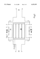
- FIG. 2 is a longitudinal section illustrating an arrangement for gas purification by parallel plates
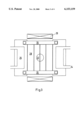
- FIG. 3 is a cross-sectional view showing the plate arrangement of FIG. 2 in a section transverse to the direction of gas flow;
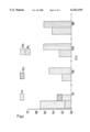
- FIG. 4 is a bar graph representation showing the conversion of various exhaust gas components at different temperatures.
- the representative embodiment of the invention shown in FIG. 1 includes an annular-gap fluidized bed reactor 1 suitable for NOx conversion for treatment and detoxification of exhaust gases from internal combustion engines used in stationary operation, or alternatively, as a small appliances.
- This arrangement is used to analyze and screen the photoactivity of semiconductor photocatalysts with respect to NOx, HC and CO conversion. For comparison purposes, the screening is done with a standard synthetic exhaust gas as described below instead of using exhaust gases from an internal combustion engine.
- the annular-gap fluidized bed reactor 1 which is made of a temperature-resistant glass transmissive to UV light, six UV luminescent lamps are arranged with a reflection jacket in the form of a lamp jacket 4.
- the annular gap of the fluidized bed reactor 1 is closed at the bottom by a gas-transmissive impact tray 3 over which a semiconductor containing 1 g titanium dioxide is disposed as a photocatalyst material.
- the titanium dioxide is of a type suitable for photocatalytic reactions and has a high BET surface area of about 300 m 2 /g. In photocatalysts employed according to the invention, surface areas from 50 m 2 /g up are acceptable in principle.
- the titanium dioxide material 2 is present as an agglomerated powder.
- the reaction gas is passed by a supply line 15 through a furnace 13 and through the impact tray 3 into the annular gap of the fluidized bed reactor 1.
- the gas flow velocity in the annular gap of the fluidized bed reactor 1 is enhanced so that the desired depth of the bed of fluidized material 2 is maintained as a homogeneous fluidized bed.
- the returned gas passes through a diaphragm pump 11 and a flowmeter 12.
- the gas passed through the reactor goes through a cyclone 8 to separate any entrained catalyst particles and then through a filter 9. After the filter 9, the gaseous mixture is removed through a three-way valve 18 and a line 16 to a quadruple mass spectrometer and an FTIR spectrometer.
- the titanium dioxide is present in the catalyst predominantly in the anatase modification and has a band gap from 3.06 eV to 3.23 eV. Thus, the absorption edge is in the UV A-interval.
- the reaction gas used in the reactor tests was adjusted to a volume flow of 500 ml/minute and had the following composition:
- the measuring operation was performed in five steps:
- the catalyst shown in FIGS. 2 and 3 has a plate structure containing catalyst supporting plates 28 coated with the catalyst material i.e., titanium dioxide. As shown in FIG. 3, the spacing of the plates 28 is fixed so that as large an areas as possible is optimally irradiated with UV light.
- the UV light comes through quartz glass plates 35 from reflector lamps 29 arranged above and below the plates 28, in a direction transverse to the gas flow.
- the exhaust gas deriving from an internal combustion engine (not shown), flows through an exhaust gas system (not shown) to the air inlet 22, along the plates 28, and to an outlet 23.
- the exhaust then flows on in the system in the usual way, in particular to a muffler.
- a thermocouple 21 is provided to check the catalyst temperature
- the catalyst housing is provided with cavities 25 capable of receiving a heating medium through inlets and outlets 24, so that a desired heating of the catalyst is achieved by heating of the entire housing.
- the invention is especially suitable for non-stationary Diesel and lean-mix (Otto) engines in motor vehicles.
Abstract
Thermal catalysts, particularly catalysts coated with precious metals, are used to reduce the concentration of CO, HC and NOx in exhaust gases from internal-combustion engines. While catalysts coated with precious metals exhibit catalytic activity from about 140° C., to ensure very low emission levels thermal catalysts need to be heated during cold starting so that the pollutants produced during the cold start react. The specification discloses a catalyst with a photocatalytic semiconductor illuminated with UV light for this purpose. Suitable for use as the photocatalytic material is e.g. titanium dioxide. This enables pollutant levels to be reduced immediately after the engine has been started and even at relatively low ambient temperatures. The invention is suitable for use with diesel engines and lean-mixture spark-ignition engines.
Description
This application is a continuation of International Application No. PCT/EP97/00881 filed Feb. 24, 1997.
This invention relates to methods and arrangements for catalytic conversion of oxides of nitrogen, hydrocarbons, and carbon monoxide in exhaust gases from internal combustion engines.
To reduce carbon monoxide (CO), hydrocarbons (HC) or oxides of nitrogen (NOx) in exhaust gases of internal combustion engines, precious-metal coated catalysts have chiefly been used. As a catalytically active coating, platinum is superior to other metals because platinum is catalytically active for converting CO and HC even at low temperatures of about 140° C. The catalytic action of platinum is stable over a long period, and is not substantially impaired by migration of the platinum, even at high exhaust gas temperatures. The primary action of a Pt catalyst, e.g. Pt/Al2 O3, is the oxidation of CO and HC to CO2 with simultaneous NOx reduction. The catalytic reduction of NOx, depending on the catalyst used, has a comparatively high dependence on temperature, and the maximum NOx reduction rate may be at temperatures below 200° C.
German Offenleggungsschrift No. 3642018 discloses a catalyst on a zeolite base for catalyzing the reaction of nitrogen oxides with hydrocarbons. The conversion of the nitrogen oxides is dependent on the hydrocarbon concentration in the exhaust gas to be treated, with only 50% reduction of the nitrogen oxides achieved at an NOx:HC ratio equal to 1. Such a zeolite catalyst may also be combined with conventional precious metal catalysts used as oxidation catalysts.
One problem with such catalysts, especially thermal catalysts, is that NOx may be partly converted into the ozone-damaging greenhouse gas N2 O.
An increase in NOx conversion, although not avoiding N2 O formation, may be achieved by a selective catalytic reduction (SCR) process using ammonia or urea as a reducing agent. The SCR process is only conditionally suitable for use with non-stationery engines, because, owing to the changing modes of operation of the engine, the danger of an NH3 release arises upon establishment of a 100% NOx reducing agent stoichiometry. In addition, during non-stationary operation, besides the catalyst, the ammonia or urea must be entrained in the exhaust gases.
At exhaust gas temperatures below 140° C., the catalysts described above are essentially inactive. To provide exhaust gas purification during engine warm-up, adsorption of the pollutant components for example on a zeolite is used. The adsorbed pollutant component from the exhaust, for example, NOx, is desorbed from the zeolite surface at exhaust temperatures of about 200° C. and passed to a precious metal catalyst which is active at that temperature for conversion. The problem in this case is the need to regenerate the zeolite surface, which must be ensured for long-term stability. In particular, potential zeolite surface poisoning presents a difficulty for this mode of exhaust gas purification.
Accordingly, it is an object of the present invention to provide a method and arrangement for purifying exhaust gases which overcomes the disadvantages of the prior art.
Another object of the invention is to provide a method and arrangement for catalytic conversion of nitrogen oxides in the exhaust of an internal combustion engine even at low temperatures.
These and other objects of the invention are attained by subjecting the exhaust gas to a semiconductor photocatalyst together with oxygen and illuminating the photocatalyst.
By using the invention, a reduction in the concentration of at least one of the components NOx, HC, and CO in the exhaust of an internal combustion engine is achieved, the exhaust gas components to be reduced being converted on a photocatalyst positioned in the exhaust stream. The reaction, which takes place in the presence of oxygen, is especially effective with respect to the components N2, CO2 and H2 O. In contradistinction to thermal catalysis, photocatalysis is employed in the present invention, semiconductors, in particular photosemiconductors, being employed as the catalyst. The photoactivity of the semiconductor with respect to the exhaust gas components is preferably achieved by excitation with a light of wavelength λ≦600 nm, in particular≦410 nm, the wavelength λ being dependent on the particular photosemiconductor used. Suitable catalysts or catalytically active substances for use in the invention are, in particular, oxides of the transition metals and/or of the rare earths, but also for example, Sb2 O4. The metal oxides may be present in mixed compounds, for example as titanates. Especially suitable are TiO2, ZnO, SrTiO3, ZrO2, Sb2 O4, CeO2. The semiconductor may or may not be doped, for example with Group VIII metals, e.g. Pt, Rh and/or Ru. This especially improves the oxidation properties of the catalysts.
The reaction preferably takes place in the presence of at least 0.5 vol. %, desirably at least 1 vol. % of O2, a temporary absence of oxygen doing no harm to the catalyst but leading to a definitely poorer NOx conversion. In other words, the reaction takes place especially well in the exhaust gases of Diesel engines or lean-mix (Otto) engines. The invention is particularly suitable when non-stationary engines are employed, i.e. internal combustion engines which have variations in operating conditions such as engine speed and load. In addition to NOx, HC and/or CO are also converted according to the invention, these components reinforcing the NOx conversion. The photocatalytic exhaust conversion according to the invention may be combined with use of conventional thermal catalysts, the conventional catalysts being located either before or after the photocatalyst, depending on the purpose. In the case of Diesel engines, in an especially preferred embodiment, the photocatalytic exhaust gas purification is preceded by an oxidation catalyst, in particular one based on precious metals, for example platinum, and/or a particle filter, employment of the oxidation catalyst being especially economical. As a result, adhesive carbon particles are removed from the exhaust gas flow before photocatalysis, so that the irradiation of the photocatalyst is not interfered with excessively by carbon particles. It has been found that, with oxidation catalysts, there is such a degradation of the hydrocarbons adhering to the carbon particles that the particles are liner and less adhesive, so that the light emission from the radiation source is not impeded by the carbon.
The exhaust can be passed over the photocatalyst in various ways. One possible arrangement passes the exhaust gases through a powder containing the photocatalyst, the powder being suspended in a fluidized bed by the exhaust gas flow. In this case the illumination may come from either or both the outside and the inside of the fluidized bed. This mode of catalytic conversion is suitable especially for stationary operation of internal combustion engines.
Another possibility for contacting the exhaust gas flow with a photosemiconductor is to provide the photosemiconductor as a porous solid bed through which the exhaust gas flow is passed. Here again, the illumination may be from without or within. In an especially preferred embodiment, the photocatalyst is present as a layer over which the exhaust gas flow passes and which is illuminated through the exhaust gas flow. Preferably the photocatalyst here is applied to a supporting structure. In this case, the photocatalyst advantageously has as large a surface area as possible. In this embodiment, the illumination may be either transverse to the exhaust gas flow, in the direction thereof, or else contrary to that direction, the latter modifications being employed in the case of a tubular structure. In an alternative arrangement, the photocatalyst is in the form of plates disposed at spaced internals, so that the exhaust gas flow is passed between the plates. In that arrangement, the illumination may be either transverse or parallel with respect to the exhaust gas flow.
Further objects and advantages of the invention will be apparent from a reading of the following description in conjunction with the accompanying drawings, in which:
FIG. 1 is a schematic diagram illustrating the arrangement of a representative fluidized bed exhaust gas purification system;
FIG. 2 is a longitudinal section illustrating an arrangement for gas purification by parallel plates;
FIG. 3 is a cross-sectional view showing the plate arrangement of FIG. 2 in a section transverse to the direction of gas flow; and
FIG. 4 is a bar graph representation showing the conversion of various exhaust gas components at different temperatures.
The representative embodiment of the invention shown in FIG. 1 includes an annular-gap fluidized bed reactor 1 suitable for NOx conversion for treatment and detoxification of exhaust gases from internal combustion engines used in stationary operation, or alternatively, as a small appliances. This arrangement is used to analyze and screen the photoactivity of semiconductor photocatalysts with respect to NOx, HC and CO conversion. For comparison purposes, the screening is done with a standard synthetic exhaust gas as described below instead of using exhaust gases from an internal combustion engine.
Around the annular-gap fluidized bed reactor 1, which is made of a temperature-resistant glass transmissive to UV light, six UV luminescent lamps are arranged with a reflection jacket in the form of a lamp jacket 4. A heating strip 5, positioned in the interior of the annular-gap fluidized bed reactor 1, serves to keep the gas passed through the reactor at the desired temperature. The annular gap of the fluidized bed reactor 1 is closed at the bottom by a gas-transmissive impact tray 3 over which a semiconductor containing 1 g titanium dioxide is disposed as a photocatalyst material. The titanium dioxide is of a type suitable for photocatalytic reactions and has a high BET surface area of about 300 m2 /g. In photocatalysts employed according to the invention, surface areas from 50 m2 /g up are acceptable in principle. The titanium dioxide material 2 is present as an agglomerated powder.
The reaction gas is passed by a supply line 15 through a furnace 13 and through the impact tray 3 into the annular gap of the fluidized bed reactor 1. By providing a continuous return of a portion of the reacted gas flow to the fresh gas with a two-way valve 10, the gas flow velocity in the annular gap of the fluidized bed reactor 1 is enhanced so that the desired depth of the bed of fluidized material 2 is maintained as a homogeneous fluidized bed. For this purpose, the returned gas passes through a diaphragm pump 11 and a flowmeter 12. The gas passed through the reactor goes through a cyclone 8 to separate any entrained catalyst particles and then through a filter 9. After the filter 9, the gaseous mixture is removed through a three-way valve 18 and a line 16 to a quadruple mass spectrometer and an FTIR spectrometer.
The titanium dioxide is present in the catalyst predominantly in the anatase modification and has a band gap from 3.06 eV to 3.23 eV. Thus, the absorption edge is in the UV A-interval. The reaction gas used in the reactor tests was adjusted to a volume flow of 500 ml/minute and had the following composition:
300 ppm NO
300 ppm propene
6 vol. % oxygen remainder nitrogen
The measuring operation was performed in five steps:
a.) Adjustment to a constant volume flow and determination of the gas composition by way of a bypass 17;
b.) Turning the three-way valves 15 and 18 to pass the stream of gas through the reactor, which had previously been flushed with nitrogen;
c.) After adjustment to a steady state of the gas concentration at the reading station, the gas was passed through the reactor for 15 hours with UV radiation;
d.) The lamp 4 was turned off;
e.) After adjusting the stationary gas concentration at the reading station, the flow of gas was diverted through the bypass 17.
The measuring operation was repeated with the same catalyst material at controlled synthetic gas temperatures of 50°, 100°, 150° and 200° C. The results are shown in FIG. 4. According to these tests, there is a continuous increase in conversion of NOx and propene with temperatures in the illuminated region rising linearly with increasing temperature of the synthetic gas from 15% NOx and 22% propene to 38% NOx and 81% propene. At the same time, NOx is reduced almost entirely to N2 and O2, and 80% of the reacted propene is oxidized to CO2. During the illumination stage, the reaction of NOx attains a maximum of 76% at only 50°, with 32% propene conversion. This confirms the efficacy of the photocatalytic conversion.
In order to permit photocatalysis to be used under the non-stationary conditions in the exhaust of an Otto or Diesel engines, the semiconductor must be immobilized. The catalyst shown in FIGS. 2 and 3 has a plate structure containing catalyst supporting plates 28 coated with the catalyst material i.e., titanium dioxide. As shown in FIG. 3, the spacing of the plates 28 is fixed so that as large an areas as possible is optimally irradiated with UV light. The UV light comes through quartz glass plates 35 from reflector lamps 29 arranged above and below the plates 28, in a direction transverse to the gas flow. The exhaust gas, deriving from an internal combustion engine (not shown), flows through an exhaust gas system (not shown) to the air inlet 22, along the plates 28, and to an outlet 23. The exhaust then flows on in the system in the usual way, in particular to a muffler. A thermocouple 21 is provided to check the catalyst temperature, the catalyst housing is provided with cavities 25 capable of receiving a heating medium through inlets and outlets 24, so that a desired heating of the catalyst is achieved by heating of the entire housing.
The invention is especially suitable for non-stationary Diesel and lean-mix (Otto) engines in motor vehicles.
Although the invention has been described herein with reference to specific embodiments, many modifications and variations therein will ready occur to those skilled in the art. Accordingly, all such variations and modifications are included within the intended scope of the invention.
Claims (17)
1. A method of catalytic conversion of NOx, HC and/or CO in an exhaust gas system of an internal combustion engine comprising supplying exhaust gas components from an internal combustion engine together with O2 to a passage extending between spaced surfaces supporting a photocatalyst containing TiO2 for reaction with the TiO2 photocatalyst and directing catalyst-activating illumination from a location outside the passage into the passage in a direction extending between the spaced surfaces to activate the photocatalyst during the reaction.
2. A method according to claim 1 wherein the photocatalyst is a photosemiconductor.
3. A method of catalytic conversion of HC and/or CO contained in an exhaust gas in an exhaust gas system of an internal combustion engine comprising supplying exhaust gas components from an internal combustion engine together with O2 to a passage extending between spaced surfaces supporting a photocatalyst for reaction with the photocatalyst and directing catalyst-activating illumination from a location outside the passage into the passage in a direction extending between the spaced surfaces to activate the photocatalyst during the reaction.
4. A method of catalytic conversion of NOx, HC and/or CO in an exhaust gas system of an internal combustion engine comprising supplying exhaust gas components from an internal combustion engine together with O2 to a passage extending between spaced surfaces supporting a semiconductor photocatalyst which contains a transition metal for reaction with the photocatalyst and directing catalyst-activating illumination from a location outside the passage into the passage in a direction extending between the spaced surfaces to activate the photocatalyst during the reaction.
5. A method according to any of claims 2 to 4 wherein the photocatalyst includes materials from the group consisting of oxides of transition metals and rare earths.
6. A method according to any of claims 2 to 4 wherein the photocatalyst is selected from the group consisting of ZnO, TiO2, SrTiO3, ZrO2, Sb2 O4 and CeO2.
7. A method according to any of claims 2 to 4 wherein the photocatalyst contains a transition metal and/or an oxide of a transition metal.
8. A method according to any of claims 1-4 wherein the illumination has a wave-length λ≦600 nm.
9. A method according to any of claims 1-4 wherein at least 0.5 vol. % oxygen is contained in the exhaust gas.
10. A method according to any of claims 1-4 wherein the exhaust gas contains NOx and oxygen, and HC and/or CO.
11. A method according to any of claims 1-4 wherein the exhaust gas is received from a Diesel combustion engine or a lean mix Otto engine.
12. A method according to any of claims 1-4 wherein the operation of the internal combustion engine is non-stationary.
13. A method according to any of claims 1-4 wherein the photocatalyst is preceded by an oxidation catalyst.
14. A method according to any of claims 1-4 wherein the photocatalyst has a carrier structure, with a coating active for catalytic conversion applied thereto.
15. A method according to claim 14 where the coating is a surface coating.
16. A method according to claims 14 wherein the exhaust gas is passed over the coating.
17. A method according to claim 16 wherein the direction of the illumination is selected from a direction of illumination transverse to the exhaust gas flow, a direction of illumination toward the exhaust gas flow, and a direction of illumination against the exhaust gas flow.
Applications Claiming Priority (3)
| Application Number | Priority Date | Filing Date | Title |
|---|---|---|---|
| DE19607862 | 1996-03-01 | ||
| DE19607862A DE19607862C2 (en) | 1996-03-01 | 1996-03-01 | Processes and devices for exhaust gas purification |
| PCT/EP1997/000881 WO1997031705A2 (en) | 1996-03-01 | 1997-02-24 | Method and device for purifying exhaust gases |
Related Parent Applications (1)
| Application Number | Title | Priority Date | Filing Date |
|---|---|---|---|
| PCT/EP1997/000881 Continuation WO1997031705A2 (en) | 1996-03-01 | 1997-02-24 | Method and device for purifying exhaust gases |
Publications (1)
| Publication Number | Publication Date |
|---|---|
| US6153159A true US6153159A (en) | 2000-11-28 |
Family
ID=7786902
Family Applications (1)
| Application Number | Title | Priority Date | Filing Date |
|---|---|---|---|
| US09/138,877 Expired - Fee Related US6153159A (en) | 1996-03-01 | 1998-08-24 | Method for purifying exhaust gases |
Country Status (4)
| Country | Link |
|---|---|
| US (1) | US6153159A (en) |
| EP (1) | EP0883434B1 (en) |
| DE (1) | DE19607862C2 (en) |
| WO (1) | WO1997031705A2 (en) |
Cited By (41)
| Publication number | Priority date | Publication date | Assignee | Title |
|---|---|---|---|---|
| US6267940B1 (en) * | 1999-08-10 | 2001-07-31 | Electric Power Research Institute, Inc. | Method for reducing NOx with an activated catalyst |
| US6468489B1 (en) * | 1999-08-10 | 2002-10-22 | Electric Power Research Institute, Inc. | Apparatus and method for decreasing contaminants present in a gas stream |
| US20020192129A1 (en) * | 2000-06-29 | 2002-12-19 | Applied Materials, Inc. | Abatement of fluorine gas from effluent |
| US6562309B2 (en) | 2000-12-26 | 2003-05-13 | Delphi Technologies, Inc. | Photocatalytic system |
| US20050215075A1 (en) * | 2002-05-30 | 2005-09-29 | Emmanuelle Veran | Integrated photochemical treatment of gases |
| US7155334B1 (en) | 2005-09-29 | 2006-12-26 | Honeywell International Inc. | Use of sensors in a state observer for a diesel engine |
| US7165399B2 (en) | 2004-12-29 | 2007-01-23 | Honeywell International Inc. | Method and system for using a measure of fueling rate in the air side control of an engine |
| US7182075B2 (en) | 2004-12-07 | 2007-02-27 | Honeywell International Inc. | EGR system |
| US7275374B2 (en) | 2004-12-29 | 2007-10-02 | Honeywell International Inc. | Coordinated multivariable control of fuel and air in engines |
| US7328577B2 (en) | 2004-12-29 | 2008-02-12 | Honeywell International Inc. | Multivariable control for an engine |
| US7357125B2 (en) | 2005-10-26 | 2008-04-15 | Honeywell International Inc. | Exhaust gas recirculation system |
| US20080116054A1 (en) * | 2004-08-16 | 2008-05-22 | Leach James T | Controlled Spectrum Ultraviolet Radiation Pollution Control Process |
| US7389773B2 (en) | 2005-08-18 | 2008-06-24 | Honeywell International Inc. | Emissions sensors for fuel control in engines |
| US7415389B2 (en) | 2005-12-29 | 2008-08-19 | Honeywell International Inc. | Calibration of engine control systems |
| US7469177B2 (en) | 2005-06-17 | 2008-12-23 | Honeywell International Inc. | Distributed control architecture for powertrains |
| US7467614B2 (en) | 2004-12-29 | 2008-12-23 | Honeywell International Inc. | Pedal position and/or pedal change rate for use in control of an engine |
| US7591135B2 (en) | 2004-12-29 | 2009-09-22 | Honeywell International Inc. | Method and system for using a measure of fueling rate in the air side control of an engine |
| US7700049B2 (en) | 2005-10-31 | 2010-04-20 | Applied Materials, Inc. | Methods and apparatus for sensing characteristics of the contents of a process abatement reactor |
| US7736599B2 (en) | 2004-11-12 | 2010-06-15 | Applied Materials, Inc. | Reactor design to reduce particle deposition during process abatement |
| US20100146948A1 (en) * | 2008-12-17 | 2010-06-17 | Caterpillar Inc. | Exhaust system promoting decomposition of reductants into gaseous products |
| US7743606B2 (en) | 2004-11-18 | 2010-06-29 | Honeywell International Inc. | Exhaust catalyst system |
| US7752840B2 (en) | 2005-03-24 | 2010-07-13 | Honeywell International Inc. | Engine exhaust heat exchanger |
| US7765792B2 (en) | 2005-10-21 | 2010-08-03 | Honeywell International Inc. | System for particulate matter sensor signal processing |
| US8265854B2 (en) | 2008-07-17 | 2012-09-11 | Honeywell International Inc. | Configurable automotive controller |
| US8504175B2 (en) | 2010-06-02 | 2013-08-06 | Honeywell International Inc. | Using model predictive control to optimize variable trajectories and system control |
| US8620461B2 (en) | 2009-09-24 | 2013-12-31 | Honeywell International, Inc. | Method and system for updating tuning parameters of a controller |
| US9650934B2 (en) | 2011-11-04 | 2017-05-16 | Honeywell spol.s.r.o. | Engine and aftertreatment optimization system |
| US9677493B2 (en) | 2011-09-19 | 2017-06-13 | Honeywell Spol, S.R.O. | Coordinated engine and emissions control system |
| US10036338B2 (en) | 2016-04-26 | 2018-07-31 | Honeywell International Inc. | Condition-based powertrain control system |
| US10124750B2 (en) | 2016-04-26 | 2018-11-13 | Honeywell International Inc. | Vehicle security module system |
| US10235479B2 (en) | 2015-05-06 | 2019-03-19 | Garrett Transportation I Inc. | Identification approach for internal combustion engine mean value models |
| US10272779B2 (en) | 2015-08-05 | 2019-04-30 | Garrett Transportation I Inc. | System and approach for dynamic vehicle speed optimization |
| US10309287B2 (en) | 2016-11-29 | 2019-06-04 | Garrett Transportation I Inc. | Inferential sensor |
| CN109966999A (en) * | 2019-05-05 | 2019-07-05 | 清华大学 | A kind of equipment that photo-thermal catalytic degradation discards refrigerant |
| US10415492B2 (en) | 2016-01-29 | 2019-09-17 | Garrett Transportation I Inc. | Engine system with inferential sensor |
| US10423131B2 (en) | 2015-07-31 | 2019-09-24 | Garrett Transportation I Inc. | Quadratic program solver for MPC using variable ordering |
| US10503128B2 (en) | 2015-01-28 | 2019-12-10 | Garrett Transportation I Inc. | Approach and system for handling constraints for measured disturbances with uncertain preview |
| CN110891680A (en) * | 2017-07-19 | 2020-03-17 | 乐金华奥斯有限公司 | Catalyst particle for treating automobile exhaust gas, method for producing same, and method for treating automobile exhaust gas using same |
| US10621291B2 (en) | 2015-02-16 | 2020-04-14 | Garrett Transportation I Inc. | Approach for aftertreatment system modeling and model identification |
| US11057213B2 (en) | 2017-10-13 | 2021-07-06 | Garrett Transportation I, Inc. | Authentication system for electronic control unit on a bus |
| US11156180B2 (en) | 2011-11-04 | 2021-10-26 | Garrett Transportation I, Inc. | Integrated optimization and control of an engine and aftertreatment system |
Families Citing this family (5)
| Publication number | Priority date | Publication date | Assignee | Title |
|---|---|---|---|---|
| DE19928975A1 (en) * | 1999-06-24 | 2000-12-28 | Volkswagen Ag | Exhaust gas-flow catalyst |
| DE19948150A1 (en) * | 1999-10-07 | 2001-04-12 | Volkswagen Ag | Arrangement and method for controlling a photochemical exhaust gas purification system of internal combustion engines |
| DE19956290A1 (en) * | 1999-11-20 | 2001-05-23 | Volkswagen Ag | Photocatalytic exhaust gas purification device for IC engines to remove pollutants comprises photocatalyst consisting of catalytically active substance fixed to carrier and radiation source |
| KR20060115939A (en) * | 2005-05-07 | 2006-11-13 | (주)네오포텍 | System for purifying exhaust gas of diesel engine and method use of the same system |
| DE102011055259A1 (en) * | 2011-11-11 | 2013-05-16 | Sumida Flexible Connections Gmbh | heating tape |
Citations (16)
| Publication number | Priority date | Publication date | Assignee | Title |
|---|---|---|---|---|
| US4755499A (en) * | 1984-10-12 | 1988-07-05 | Noxso Corporation | Sorbent for removing nitrogen oxides, sulfur oxides and hydrogen sulfide from gas streams |
| US4798711A (en) * | 1984-10-12 | 1989-01-17 | Noxso Corporation | Processes for removing nitrogen oxides, sulfur oxides and hydrogen sulfide from gas streams |
| US4849274A (en) * | 1987-06-19 | 1989-07-18 | W. R. Grace & Co.-Conn. | Honeycomb fluid conduit |
| US4940569A (en) * | 1984-10-12 | 1990-07-10 | Noxso Corporation | Sorbent and processes for removing nitrogen oxides, sulfur oxides and hydrogen sulfide from gas streams |
| US4980040A (en) * | 1989-06-26 | 1990-12-25 | Trustees Of Boston University | Photopromoted method for decomposing oxides of nitrogen into environmentally compatible products |
| WO1991009823A1 (en) * | 1990-01-04 | 1991-07-11 | Trustees Of Boston University | Photocatalytic process for degradation of organic materials in a vaporized or gaseous state |
| US5240682A (en) * | 1991-05-06 | 1993-08-31 | W. R. Grace & Co.-Conn | Reinforced corrugated thin metal foil strip useful in a catalytic converter core, a catalytic converter core containing said strip and an electrically heatable catalytic converter containing said core |
| DE4320218A1 (en) * | 1993-01-18 | 1994-07-21 | Pcp Photocatalytic Purificatio | Contaminated gas, waste gas and vapour purificn. - by photocatalysis on semiconductor oxide, esp. titanium di:oxide treated with electrolyte increasing capillary condensation and doped with inorganic halogen cpd. |
| US5362463A (en) * | 1992-08-26 | 1994-11-08 | University Of De | Process for removing NOx from combustion zone gases by adsorption |
| US5388406A (en) * | 1991-10-29 | 1995-02-14 | Toyota Jidosha Kabushiki Kaisha | NOx decreasing apparatus for an internal combustion engine |
| US5402641A (en) * | 1992-07-24 | 1995-04-04 | Toyota Jidosha Kabushiki Kaisha | Exhaust gas purification apparatus for an internal combustion engine |
| US5406790A (en) * | 1992-12-11 | 1995-04-18 | Toyota Jidosha Kabushiki Kaisha | Exhaust gas purification device for an engine |
| CA2137175A1 (en) * | 1993-12-04 | 1995-06-05 | Bernd Engler | Process for accelerating the rate of heating of fixed bed catalysts by supplying supplementary energy |
| US5633217A (en) * | 1994-09-12 | 1997-05-27 | Corning Incorporated | Method of making a high strength catalyst, catalyst support or adsorber |
| US5665321A (en) * | 1994-02-04 | 1997-09-09 | Goal Line Environmental Technologies | Process for the reaction and absorption of gaseous air pollutants, apparatus therefor and method of making same |
| US5702675A (en) * | 1994-12-16 | 1997-12-30 | Toyota Jidosha Kabushiki Kaisha | Catalyst for purifying exhaust gases and process for producing the same |
Family Cites Families (5)
| Publication number | Priority date | Publication date | Assignee | Title |
|---|---|---|---|---|
| DE3642018A1 (en) * | 1985-12-21 | 1987-06-25 | Volkswagen Ag | Process and apparatus for the reduction of nitrogen oxides |
| DE3642472A1 (en) * | 1986-12-12 | 1988-06-23 | Bbc Brown Boveri & Cie | Process and apparatus for purifying exhaust gases |
| US5045288A (en) * | 1989-09-15 | 1991-09-03 | Arizona Board Of Regents, A Body Corporate Acting On Behalf Of Arizona State University | Gas-solid photocatalytic oxidation of environmental pollutants |
| DE4110227C2 (en) * | 1991-03-28 | 1996-07-11 | Deutsche Forsch Luft Raumfahrt | catalyst |
| DE4240558A1 (en) * | 1992-12-02 | 1994-06-09 | Franz Dietrich Oeste | Photo-catalytic purificn. of gases and brines in a closed chamber - comprising using supported catalysts e.g. titanium di:oxide and palladium or platinum regenerated by washing and short wave light source |
-
1996
- 1996-03-01 DE DE19607862A patent/DE19607862C2/en not_active Expired - Fee Related
-
1997
- 1997-02-24 WO PCT/EP1997/000881 patent/WO1997031705A2/en active IP Right Grant
- 1997-02-24 EP EP97903368A patent/EP0883434B1/en not_active Expired - Lifetime
-
1998
- 1998-08-24 US US09/138,877 patent/US6153159A/en not_active Expired - Fee Related
Patent Citations (16)
| Publication number | Priority date | Publication date | Assignee | Title |
|---|---|---|---|---|
| US4798711A (en) * | 1984-10-12 | 1989-01-17 | Noxso Corporation | Processes for removing nitrogen oxides, sulfur oxides and hydrogen sulfide from gas streams |
| US4940569A (en) * | 1984-10-12 | 1990-07-10 | Noxso Corporation | Sorbent and processes for removing nitrogen oxides, sulfur oxides and hydrogen sulfide from gas streams |
| US4755499A (en) * | 1984-10-12 | 1988-07-05 | Noxso Corporation | Sorbent for removing nitrogen oxides, sulfur oxides and hydrogen sulfide from gas streams |
| US4849274A (en) * | 1987-06-19 | 1989-07-18 | W. R. Grace & Co.-Conn. | Honeycomb fluid conduit |
| US4980040A (en) * | 1989-06-26 | 1990-12-25 | Trustees Of Boston University | Photopromoted method for decomposing oxides of nitrogen into environmentally compatible products |
| WO1991009823A1 (en) * | 1990-01-04 | 1991-07-11 | Trustees Of Boston University | Photocatalytic process for degradation of organic materials in a vaporized or gaseous state |
| US5240682A (en) * | 1991-05-06 | 1993-08-31 | W. R. Grace & Co.-Conn | Reinforced corrugated thin metal foil strip useful in a catalytic converter core, a catalytic converter core containing said strip and an electrically heatable catalytic converter containing said core |
| US5388406A (en) * | 1991-10-29 | 1995-02-14 | Toyota Jidosha Kabushiki Kaisha | NOx decreasing apparatus for an internal combustion engine |
| US5402641A (en) * | 1992-07-24 | 1995-04-04 | Toyota Jidosha Kabushiki Kaisha | Exhaust gas purification apparatus for an internal combustion engine |
| US5362463A (en) * | 1992-08-26 | 1994-11-08 | University Of De | Process for removing NOx from combustion zone gases by adsorption |
| US5406790A (en) * | 1992-12-11 | 1995-04-18 | Toyota Jidosha Kabushiki Kaisha | Exhaust gas purification device for an engine |
| DE4320218A1 (en) * | 1993-01-18 | 1994-07-21 | Pcp Photocatalytic Purificatio | Contaminated gas, waste gas and vapour purificn. - by photocatalysis on semiconductor oxide, esp. titanium di:oxide treated with electrolyte increasing capillary condensation and doped with inorganic halogen cpd. |
| CA2137175A1 (en) * | 1993-12-04 | 1995-06-05 | Bernd Engler | Process for accelerating the rate of heating of fixed bed catalysts by supplying supplementary energy |
| US5665321A (en) * | 1994-02-04 | 1997-09-09 | Goal Line Environmental Technologies | Process for the reaction and absorption of gaseous air pollutants, apparatus therefor and method of making same |
| US5633217A (en) * | 1994-09-12 | 1997-05-27 | Corning Incorporated | Method of making a high strength catalyst, catalyst support or adsorber |
| US5702675A (en) * | 1994-12-16 | 1997-12-30 | Toyota Jidosha Kabushiki Kaisha | Catalyst for purifying exhaust gases and process for producing the same |
Cited By (61)
| Publication number | Priority date | Publication date | Assignee | Title |
|---|---|---|---|---|
| US6468489B1 (en) * | 1999-08-10 | 2002-10-22 | Electric Power Research Institute, Inc. | Apparatus and method for decreasing contaminants present in a gas stream |
| US6267940B1 (en) * | 1999-08-10 | 2001-07-31 | Electric Power Research Institute, Inc. | Method for reducing NOx with an activated catalyst |
| US20020192129A1 (en) * | 2000-06-29 | 2002-12-19 | Applied Materials, Inc. | Abatement of fluorine gas from effluent |
| US20070022958A1 (en) * | 2000-06-29 | 2007-02-01 | Shamouil Shamouilian | Abatement of fluorine gas from effluent |
| US6562309B2 (en) | 2000-12-26 | 2003-05-13 | Delphi Technologies, Inc. | Photocatalytic system |
| US20050215075A1 (en) * | 2002-05-30 | 2005-09-29 | Emmanuelle Veran | Integrated photochemical treatment of gases |
| US20080116054A1 (en) * | 2004-08-16 | 2008-05-22 | Leach James T | Controlled Spectrum Ultraviolet Radiation Pollution Control Process |
| US7498009B2 (en) | 2004-08-16 | 2009-03-03 | Dana Uv, Inc. | Controlled spectrum ultraviolet radiation pollution control process |
| US7736599B2 (en) | 2004-11-12 | 2010-06-15 | Applied Materials, Inc. | Reactor design to reduce particle deposition during process abatement |
| US7985379B2 (en) | 2004-11-12 | 2011-07-26 | Applied Materials, Inc. | Reactor design to reduce particle deposition during process abatement |
| US7743606B2 (en) | 2004-11-18 | 2010-06-29 | Honeywell International Inc. | Exhaust catalyst system |
| US7182075B2 (en) | 2004-12-07 | 2007-02-27 | Honeywell International Inc. | EGR system |
| USRE44452E1 (en) | 2004-12-29 | 2013-08-27 | Honeywell International Inc. | Pedal position and/or pedal change rate for use in control of an engine |
| US7328577B2 (en) | 2004-12-29 | 2008-02-12 | Honeywell International Inc. | Multivariable control for an engine |
| US7275374B2 (en) | 2004-12-29 | 2007-10-02 | Honeywell International Inc. | Coordinated multivariable control of fuel and air in engines |
| US7467614B2 (en) | 2004-12-29 | 2008-12-23 | Honeywell International Inc. | Pedal position and/or pedal change rate for use in control of an engine |
| US7165399B2 (en) | 2004-12-29 | 2007-01-23 | Honeywell International Inc. | Method and system for using a measure of fueling rate in the air side control of an engine |
| US7591135B2 (en) | 2004-12-29 | 2009-09-22 | Honeywell International Inc. | Method and system for using a measure of fueling rate in the air side control of an engine |
| US7752840B2 (en) | 2005-03-24 | 2010-07-13 | Honeywell International Inc. | Engine exhaust heat exchanger |
| US7469177B2 (en) | 2005-06-17 | 2008-12-23 | Honeywell International Inc. | Distributed control architecture for powertrains |
| US8109255B2 (en) | 2005-08-18 | 2012-02-07 | Honeywell International Inc. | Engine controller |
| US7878178B2 (en) | 2005-08-18 | 2011-02-01 | Honeywell International Inc. | Emissions sensors for fuel control in engines |
| US8360040B2 (en) | 2005-08-18 | 2013-01-29 | Honeywell International Inc. | Engine controller |
| US20080249697A1 (en) * | 2005-08-18 | 2008-10-09 | Honeywell International Inc. | Emissions sensors for fuel control in engines |
| US7389773B2 (en) | 2005-08-18 | 2008-06-24 | Honeywell International Inc. | Emissions sensors for fuel control in engines |
| US20110087420A1 (en) * | 2005-08-18 | 2011-04-14 | Honeywell International Inc. | Engine controller |
| US7155334B1 (en) | 2005-09-29 | 2006-12-26 | Honeywell International Inc. | Use of sensors in a state observer for a diesel engine |
| US8165786B2 (en) | 2005-10-21 | 2012-04-24 | Honeywell International Inc. | System for particulate matter sensor signal processing |
| US7765792B2 (en) | 2005-10-21 | 2010-08-03 | Honeywell International Inc. | System for particulate matter sensor signal processing |
| US7357125B2 (en) | 2005-10-26 | 2008-04-15 | Honeywell International Inc. | Exhaust gas recirculation system |
| US7736600B2 (en) | 2005-10-31 | 2010-06-15 | Applied Materials, Inc. | Apparatus for manufacturing a process abatement reactor |
| US7700049B2 (en) | 2005-10-31 | 2010-04-20 | Applied Materials, Inc. | Methods and apparatus for sensing characteristics of the contents of a process abatement reactor |
| US7415389B2 (en) | 2005-12-29 | 2008-08-19 | Honeywell International Inc. | Calibration of engine control systems |
| US8265854B2 (en) | 2008-07-17 | 2012-09-11 | Honeywell International Inc. | Configurable automotive controller |
| US20100146948A1 (en) * | 2008-12-17 | 2010-06-17 | Caterpillar Inc. | Exhaust system promoting decomposition of reductants into gaseous products |
| US8620461B2 (en) | 2009-09-24 | 2013-12-31 | Honeywell International, Inc. | Method and system for updating tuning parameters of a controller |
| US9170573B2 (en) | 2009-09-24 | 2015-10-27 | Honeywell International Inc. | Method and system for updating tuning parameters of a controller |
| US8504175B2 (en) | 2010-06-02 | 2013-08-06 | Honeywell International Inc. | Using model predictive control to optimize variable trajectories and system control |
| US9677493B2 (en) | 2011-09-19 | 2017-06-13 | Honeywell Spol, S.R.O. | Coordinated engine and emissions control system |
| US10309281B2 (en) | 2011-09-19 | 2019-06-04 | Garrett Transportation I Inc. | Coordinated engine and emissions control system |
| US9650934B2 (en) | 2011-11-04 | 2017-05-16 | Honeywell spol.s.r.o. | Engine and aftertreatment optimization system |
| US11619189B2 (en) | 2011-11-04 | 2023-04-04 | Garrett Transportation I Inc. | Integrated optimization and control of an engine and aftertreatment system |
| US11156180B2 (en) | 2011-11-04 | 2021-10-26 | Garrett Transportation I, Inc. | Integrated optimization and control of an engine and aftertreatment system |
| US10503128B2 (en) | 2015-01-28 | 2019-12-10 | Garrett Transportation I Inc. | Approach and system for handling constraints for measured disturbances with uncertain preview |
| US10621291B2 (en) | 2015-02-16 | 2020-04-14 | Garrett Transportation I Inc. | Approach for aftertreatment system modeling and model identification |
| US11687688B2 (en) | 2015-02-16 | 2023-06-27 | Garrett Transportation I Inc. | Approach for aftertreatment system modeling and model identification |
| US10235479B2 (en) | 2015-05-06 | 2019-03-19 | Garrett Transportation I Inc. | Identification approach for internal combustion engine mean value models |
| US11687047B2 (en) | 2015-07-31 | 2023-06-27 | Garrett Transportation I Inc. | Quadratic program solver for MPC using variable ordering |
| US10423131B2 (en) | 2015-07-31 | 2019-09-24 | Garrett Transportation I Inc. | Quadratic program solver for MPC using variable ordering |
| US11144017B2 (en) | 2015-07-31 | 2021-10-12 | Garrett Transportation I, Inc. | Quadratic program solver for MPC using variable ordering |
| US10272779B2 (en) | 2015-08-05 | 2019-04-30 | Garrett Transportation I Inc. | System and approach for dynamic vehicle speed optimization |
| US11180024B2 (en) | 2015-08-05 | 2021-11-23 | Garrett Transportation I Inc. | System and approach for dynamic vehicle speed optimization |
| US11506138B2 (en) | 2016-01-29 | 2022-11-22 | Garrett Transportation I Inc. | Engine system with inferential sensor |
| US10415492B2 (en) | 2016-01-29 | 2019-09-17 | Garrett Transportation I Inc. | Engine system with inferential sensor |
| US10124750B2 (en) | 2016-04-26 | 2018-11-13 | Honeywell International Inc. | Vehicle security module system |
| US10036338B2 (en) | 2016-04-26 | 2018-07-31 | Honeywell International Inc. | Condition-based powertrain control system |
| US10309287B2 (en) | 2016-11-29 | 2019-06-04 | Garrett Transportation I Inc. | Inferential sensor |
| CN110891680A (en) * | 2017-07-19 | 2020-03-17 | 乐金华奥斯有限公司 | Catalyst particle for treating automobile exhaust gas, method for producing same, and method for treating automobile exhaust gas using same |
| US11697109B2 (en) | 2017-07-19 | 2023-07-11 | Lg Hausys, Ltd. | Catalyst particles for treating vehicle exhaust gas, preparation method therefor, and method for treating vehicle exhaust gas by using same |
| US11057213B2 (en) | 2017-10-13 | 2021-07-06 | Garrett Transportation I, Inc. | Authentication system for electronic control unit on a bus |
| CN109966999A (en) * | 2019-05-05 | 2019-07-05 | 清华大学 | A kind of equipment that photo-thermal catalytic degradation discards refrigerant |
Also Published As
| Publication number | Publication date |
|---|---|
| WO1997031705A3 (en) | 1997-12-24 |
| EP0883434A2 (en) | 1998-12-16 |
| WO1997031705A2 (en) | 1997-09-04 |
| DE19607862A1 (en) | 1997-09-04 |
| DE19607862C2 (en) | 1998-10-29 |
| EP0883434B1 (en) | 2003-05-14 |
Similar Documents
| Publication | Publication Date | Title |
|---|---|---|
| US6153159A (en) | Method for purifying exhaust gases | |
| EP0666099B1 (en) | Method of removing nitrogen oxides contained in exhaust gas | |
| JP3050566B2 (en) | Palladium-containing ceria-supported platinum catalyst and catalyst assembly containing the same | |
| Taylor | Nitric oxide catalysis in automotive exhaust systems | |
| Matsumoto et al. | NOx storage-reduction catalyst for automotive exhaust with improved tolerance against sulfur poisoning | |
| US6066587A (en) | Catalyst for purifying exhaust gas | |
| US5531972A (en) | Staged three-way conversion catalyst and method of using the same | |
| EP0283913B1 (en) | Process for removal of nox from fluid streams | |
| JP4927862B2 (en) | Selective catalytic reduction of nitrogen oxides with hydrogen. | |
| JPH01228546A (en) | Catalyst and method for purifying exhaust gas of internal combustion engine | |
| CA2288105C (en) | Exhaust gas purification method and exhaust gas purification catalyst | |
| EP0562516B1 (en) | Method for purifying exhaust gas | |
| US5670443A (en) | Exhaust gas cleaner and method for cleaning exhaust gas | |
| KR20010033611A (en) | Catalytic Converter System for Internal Combustion Engine Powered Vehicles | |
| US5399324A (en) | Two-stage catalyst system for lean burn engines | |
| US6767526B1 (en) | Method for treating by combustion carbon-containing particles in an internal combustion engine exhaust circuit | |
| KR20080027720A (en) | Gas purification method, gas purification apparatus and gas purification catalyst | |
| US4448756A (en) | Process for treatment of exhaust gases | |
| EP0722767A1 (en) | Catalyst for purifying exhaust gases | |
| US5972828A (en) | Method of manufacturing catalyst for cleaning exhaust gas released from internal combustion engine, and catalyst for the same | |
| JPH07829A (en) | Non-metal catalyst system for lean-burn engine | |
| JPH06378A (en) | Catalyst for purification of exhaust gas | |
| JPH0857313A (en) | New catalyst containing platinum group metal and its preparation | |
| JP4290391B2 (en) | Method and apparatus for catalytic removal of nitrogen oxides | |
| Muench et al. | Extruded zeolite based honeycomb catalyst for nox removal from diesel exhaust |
Legal Events
| Date | Code | Title | Description |
|---|---|---|---|
| AS | Assignment |
Owner name: VOLKSWAGEN AG, GERMANY Free format text: ASSIGNMENT OF ASSIGNORS INTEREST;ASSIGNORS:ENGELER, WERNER;NEYER, DIETER;KOSTERS, MARTINA;AND OTHERS;REEL/FRAME:011117/0299;SIGNING DATES FROM 19980708 TO 19980812 |
|
| FEPP | Fee payment procedure |
Free format text: PAYOR NUMBER ASSIGNED (ORIGINAL EVENT CODE: ASPN); ENTITY STATUS OF PATENT OWNER: LARGE ENTITY |
|
| FPAY | Fee payment |
Year of fee payment: 4 |
|
| REMI | Maintenance fee reminder mailed | ||
| LAPS | Lapse for failure to pay maintenance fees | ||
| STCH | Information on status: patent discontinuation |
Free format text: PATENT EXPIRED DUE TO NONPAYMENT OF MAINTENANCE FEES UNDER 37 CFR 1.362 |
|
| FP | Lapsed due to failure to pay maintenance fee |
Effective date: 20081128 |