US6152880A - Self-diagnostic blood pressure measuring apparatus - Google Patents
Self-diagnostic blood pressure measuring apparatus Download PDFInfo
- Publication number
- US6152880A US6152880A US09/273,569 US27356999A US6152880A US 6152880 A US6152880 A US 6152880A US 27356999 A US27356999 A US 27356999A US 6152880 A US6152880 A US 6152880A
- Authority
- US
- United States
- Prior art keywords
- systolic
- diastolic
- warning
- range
- indicators
- Prior art date
- Legal status (The legal status is an assumption and is not a legal conclusion. Google has not performed a legal analysis and makes no representation as to the accuracy of the status listed.)
- Expired - Lifetime
Links
Images

Classifications
-
- A—HUMAN NECESSITIES
- A61—MEDICAL OR VETERINARY SCIENCE; HYGIENE
- A61B—DIAGNOSIS; SURGERY; IDENTIFICATION
- A61B5/00—Measuring for diagnostic purposes; Identification of persons
- A61B5/02—Detecting, measuring or recording pulse, heart rate, blood pressure or blood flow; Combined pulse/heart-rate/blood pressure determination; Evaluating a cardiovascular condition not otherwise provided for, e.g. using combinations of techniques provided for in this group with electrocardiography or electroauscultation; Heart catheters for measuring blood pressure
- A61B5/021—Measuring pressure in heart or blood vessels
- A61B5/022—Measuring pressure in heart or blood vessels by applying pressure to close blood vessels, e.g. against the skin; Ophthalmodynamometers
- A61B5/02233—Occluders specially adapted therefor
-
- A—HUMAN NECESSITIES
- A61—MEDICAL OR VETERINARY SCIENCE; HYGIENE
- A61B—DIAGNOSIS; SURGERY; IDENTIFICATION
- A61B5/00—Measuring for diagnostic purposes; Identification of persons
- A61B5/02—Detecting, measuring or recording pulse, heart rate, blood pressure or blood flow; Combined pulse/heart-rate/blood pressure determination; Evaluating a cardiovascular condition not otherwise provided for, e.g. using combinations of techniques provided for in this group with electrocardiography or electroauscultation; Heart catheters for measuring blood pressure
- A61B5/024—Detecting, measuring or recording pulse rate or heart rate
- A61B5/0255—Recording instruments specially adapted therefor
Definitions
- the present invention is directed to a self-diagnostic blood pressure measuring apparatus, more particularly to such apparatus which notifies an user of a blood pressure warning after displaying systolic and diastolic pressures.
- Japanese Patent Publication No. 60-132538 discloses a prior blood pressure measuring apparatus which has, in addition to displaying measured systolic and diastolic pressures, a self-diagnostic function of indicating a particular blood pressure stage in which a combination of the measured systolic and diastolic pressures is classified according to regulation by World Health Organization (WHO).
- WHO World Health Organization
- the display includes three separate zones defined by systolic values and diastolic values respectively given along x-axis and y-axis to have normal blood pressure zone (where systolic pressure ⁇ 140 mmHg and systolic pressure ⁇ 90 mmHg), boundary line high pressure zone (where 140 mmHg ⁇ systolic pressure ⁇ 160 mmHg and 90 mmHg ⁇ diastolic pressure ⁇ 95 mmHg) and a high pressure zone (160 mmHg ⁇ systolic pressure and diastolic pressure ⁇ 95 mmHg).
- this display is difficult to indicate direct relation between the individual blood pressures being measured and the associated zone.
- the display is unable to give a warning by reference to the zone.
- the prior apparatus is found insufficient to give direct and exact blood pressure information to the user.
- the present invention has been accomplished in view of the above problem to provide an improved diagnostic blood pressure measuring apparatus which is capable of displaying measured blood pressure values as well as information indicative of corresponding blood pressure zones, and therefore capable of displaying blood pressure warnings together with the measured blood pressure values even if only one of the systolic and diastolic pressures is determined to be abnormal.
- the diagnostic blood pressure measuring apparatus in accordance with the present invention has a detector which is applied to a portion of a human body to measure systolic and diastolic pressures thereof, a display unit having first and second numeric indicators respectively for displaying individual numerical values of the measured systolic and diastolic pressures.
- a diagnosing circuit is included to compare the measured systolic and diastolic pressures respectively with predetermined systolic and diastolic reference ranges so as to provide a systolic warning when the systolic pressure is out of the systolic reference range and provide a diastolic warning when the diastolic pressure is out of the diastolic reference range.
- the display unit includes a warning display section which notify the systolic and diastolic warnings, individually.
- the systolic and diastolic warnings can be individually displayed together with the measured systolic and diastolic pressures appearing at the first and second numeric indicators, thereby providing detailed blood pressure information for immediate recognition by the user.
- the diagnosing circuit includes predetermined high systolic and diastolic reference levels which are higher than upper limits respectively of the systolic and diastolic reference ranges. Consequently, there are defined with regard to the systolic pressure, a quasi-hypertension systolic range (also referred to as a boundary line hypertension systolic range) between the upper limit of the systolic reference range and the high systolic reference level and a hypertension systolic range exceeding the high systolic reference level.
- a quasi-hypertension systolic range also referred to as a boundary line hypertension systolic range
- a quasi-hypertension diastolic range (also referred to as a boundary line hypertension diastolic range) between the upper limit of the diastolic reference range and the high diastolic reference level and a hypertension diastolic range exceeding the high diastolic reference level.
- the diagnosing circuit compares the measured systolic and diastolic pressures respectively with the high systolic and diastolic reference levels to give
- the warning display section is preferred to include a highlighting circuit of blinking the first and second numeric indicators respectively in response to the systolic and diastolic warnings so that the blood pressure value determined to be abnormal can be immediately appealed to the eyes of the user.
- the highlighting circuit may be arranged to change colors of the first and second numeric indicators upon receiving the warnings in order to notify the measured blood pressure value and abnormality thereof simultaneously and directly to the user.
- the warning display section may include first and second warning indicators which are provided separately from the first and second numerical indicators, respectively.
- the first and second warning indicators are caused to turn on or blink respectively in response to the systolic and diastolic warnings for giving individual warnings to the user.
- the warning display section includes a highlighting circuit of blinking the first and second numerical indicators, and first and second warning indicators formed separately from the first and second numerical indicators.
- the first and second warning indicators are caused to turn on or blink respectively in response to the systolic and diastol warnings, enabling to give detailed warnings. That is, the first and second numerical indicators are made to highlight the respective blood pressure values irrespective of the distinction between the high-level and low-level warnings, while the first and second warning indicators are caused to turn on or blink only in response to the high-level warnings.
- the warning display section may include a highlighting circuit of blinking the first and second numerical indicators, and a separately formed single warning indicator.
- the single warning indicator is caused to blink only in response to the high-level systolic or high-level diastolic warnings, enabling to give distinctive identification of whether the measure blood pressure corresponds to the pseudo hypertension range (boundary line hypertension range) or hypertension range for immediate recognition by the user with a simple structure.
- FIG. 1 is a partial plan view of a self-diagnostic blood pressure measuring apparatus in accordance with a preferred embodiment of the present invention
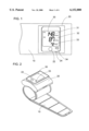
- FIG. 2 is a perspective view of the above apparatus
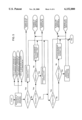
- FIG. 3 is a graph showing reference levels utilized in the apparatus
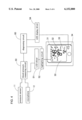
- FIG. 4 is a block diagram showing a configuration of the apparatus
- FIG. 5 is a flow chart showing the operation of the apparatus
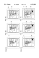
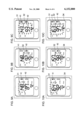
- FIG. 6, composed of FIGS. 6A to 6C, explains a warning scheme, in which FIG. 6A indicates a condition when only the systolic pressure is within the boundary line hypertension range, FIG. 6B indicates a condition when only the diastolic pressure is within the boundary line hypertension range, and FIG. 6C indicates a condition when both of the systolic and diastolic pressures are within the boundary line hypertension range;
- FIG. 7 composed of FIGS. 7A to 7C, explains a warning scheme, in which FIG. 7A indicates a condition when only the systolic pressure is within the hypertension range, FIG. 7B indicates a condition when only the diastolic pressure is within the hypertension range, and FIG. 7C indicates a condition when both of the systolic and diastolic pressures are within the hypertension range;
- FIG. 8 is a plan view showing a display unit which may be utilized in the above apparatus.
- FIG. 9 composed of FIGS. 9A to 9C, explains a warning scheme for a self-diagnostic blood pressure measuring apparatus in accordance with another embodiment of the present invention, in which FIG. 9A indicates a condition when only the systolic pressure is within the boundary line hypertension range, FIG. 9B indicates a condition when only the diastolic pressure is within the boundary line hypertension range, and
- FIG. 9C indicates a condition when both of the systolic and diastolic pressures are within the boundary line hypertension range.
- FIG. 10 composed of FIGS. 10A to 10C, explains a warning scheme of the above apparatus, in which FIG. 10A indicates a condition when only the systolic pressure is within the hypertension range, FIG. 10B indicates a condition when only the diastolic pressure is within the hypertension range, and FIG. 10C indicates a condition when both of the systolic and diastolic pressures are within the hypertension range;
- FIG. 2 illustrates a self-diagnostic blood pressure measuring apparatus in accordance with a preferred embodiment of the present invention.
- the apparatus includes an occluding cuff 10 adapted to be wound around a human's wrist, a housing 20 secured to a portion of the cuff 10.
- the housing 20 has a start switch 22 for starting a blood pressure measurement and a display unit for the measured results.
- the display unit is composed of a liquid-crystal display (LCD) 30 and a light emitting diode (LED) lamp 34.
- the housing 20 incorporates a pneumatic pump for inflating or collapsing the cuff 10 and an electronic circuitry for the blood pressure measurement.
- a microphone for picking up the Korotocoff sound and a pressure sensor for detecting an occluding pressure. Based upon the information of the Korotocoff sound and the pressure, a blood pressure measuring circuit 50 within the housing 20 operates to measure systolic and diastolic pressures. Further, a heat rate is also measured based upon the information from the microphone.
- LCD 30 forming the display unit includes a first numerical indicator 31, a second numerical indicator 32, and a heart rate indicator 33 for indication of the measured systolic pressure, diastolic pressure and heart rate, respectively.
- LED lamp 34 is disposed in the top face of the housing 20 adjacent to LCD 30 for indication of a diagnostic result as explained later.
- the above electronic circuitry includes a diagnostic circuit 60 which makes a blood pressure diagnosis by comparing the measured systolic and diastolic pressures respectively with predetermined reference values which are set for each of the systolic and diastolic pressures.
- a diagnostic circuit 60 which makes a blood pressure diagnosis by comparing the measured systolic and diastolic pressures respectively with predetermined reference values which are set for each of the systolic and diastolic pressures.
- These reference values correspond to regulations specified by the World Health Organization (WHO) and therefore define a hypotension range, normal range, boundary line hyper
- the start switch 22 is pressed to initiate a measurement mode in which the pneumatic pump is actuated to inflate the cuff 10 followed by discharging the air gradually from the cuff.
- pressure information from the pressure sensor 11 and the Korotocoff sound information from the microphone 12 are processed at the blood pressure measuring circuit 50 to measure the systolic pressure, the diastolic pressure, and the heart rate.
- the apparatus goes into a diagnostic mode where the diagnostic circuit 60 compares the measured systolic and diastolic pressures with the above reference levels S1, S2, S3; D2, D3 in order to judge to which ranges do the systolic and diastolic pressure belong individually, and resulting warning signals to a highlighting circuit 52 and an LED display driving circuit 54.
- the highlighting circuit 52 is actuated to blink the first and second numerical indicators 31 and 32.
- the LED display driving circuit 54 is actuated to blink the LED lamp 34. Followings are examples of the operation.
- the diagnostic circuit 60 determines that the systolic pressure lies within the boundary line hypertension range to provide a low-level systolic pressure hypertension warning signal L-SYS, thereby blinking the first numerical indicator 31 displaying the systolic pressure, as shown in FIG. 6A.
- the diagnostic circuit 60 determines that the diastolic pressure lies within the boundary line hypertension range to provide a low-level diastolic pressure hypertension warning signal L-DIA, thereby blinking the second numerical indicator 32 displaying the diastolic pressure, as shown in FIG. 6B.
- the diagnostic circuit 60 issues the low-level systolic and diastolic pressure hypertension warning signals L-SYS and L-DIA, thereby blinking the first and second numerical indicators 31, 32, as shown in FIG. 6C.
- the diagnostic circuit 60 determines that the systolic pressure lies within the hypertension range to provide a high-level systolic pressure hypertension warning signal H-SYS, thereby blinking the first numerical indicator 31 displaying the systolic pressure, and at the same time blinking the LED lamp 34, as shown in FIG. 7A.
- the diagnostic circuit 60 determines that the diastolic pressure lies within the hypertension range to provide a high-level diastolic pressure hypertension warning signal H-DIA, thereby blinking the second numerical indicator 32 displaying the diastolic pressure, and at the same time blinking the LED lamp 34, as shown in FIG. 7B.
- the diagnostic circuit 60 issues the high-level systolic and diastolic pressure hypertension warning signals H-SYS and H-DIA, thereby blinking the first and second numerical indicators 31, 32, and at the same time blinking the LED lamp 34, as shown in FIG. 7C.
- the blinking of the first and second numerical indicators 31 and 32 can notify the user that which or both of the systolic and diastolic pressures is to receive attention in direct reference to the actual blood pressure value.
- the blinking of LED lamp 34 can lead to easily recognition by the user of severity of the hypertension.
- the diagnostic circuit 60 When the systolic pressure is determined to be less than the reference values S1, the diagnostic circuit 60 provides a systolic pressure hypotension warning signal SYS-L, causing the LED lamp 34 to turn on for displaying a hypotension warning. At this occurrence, no blinking is made at the first and second numerical indicators 31 and 32.
- the diagnostic blood pressure measuring apparatus of the present invention includes a diagnosis disable button 24 which is disposed on the side of the housing 20 to cancel the above diagnostic mode upon being pressed.
- the background color is changed from a normal color to a highlighted color in response to that at least one of the systolic and diastolic pressures are determined to be within the hypertension range.
- the warning indicator is composed of four (4) vertically aligned lamps which corresponds to different diagnostic results and are selectively turned on according to the particular diagnostic result. That is, when either or both of the measured systolic and diastolic pressure pressures are determined to be within the hypertension range, the uppermost lamp will be turned on for warning the serious hypertension. When either or both of the systolic and diastolic pressure are determined to be within the boundary line hypertension range, the second lamp will be turned on for warning moderate hypertension. When both of the systolic and diastolic pressure is within the normal range, the third lamp will be turned on for indication of the normal condition.
- the lowermost lamp When either or both of the systolic and diastolic pressures are found to be within the hypotension range, the lowermost lamp will be turned on for hypotension warning.
- the systolic and diastolic pressures with which the warnings are made are highlighted respectively in the same manner as in the previous embodiment.
- FIGS. 9 and 10 illustrate a display scheme for the self-diagnostic blood pressure measuring apparatus in accordance with a second embodiment of the present invention.
- the present embodiment utilizes first and second warning indicators 41 and 42 instead of the LED lamp 34.
- the first and second warning indicators 41 and 42 are provided within the LED 30 in proximity respectively to the first and second numerical indicators 31 and 32.
- the warning indicators are caused to turn on or blink in order to warn that the measured pressures are within either of the boundary line hypertension range or the hypertension range, to indicate to which range the measure pressures belong.
- Each of the warning-indicators is composed of three vertically aligned dots for warning based upon the diagnostic result at the diagnostic circuit.
- the upper dot is caused to turn on or blink when either or both of the measured blood pressures are determined to be within the hypertension range.
- the middle dot is caused to turn on or blink when either or both of the measured blood pressures are determined to be within the boundary line hypertension range.
- the lower dot is caused to turn on or blink when either or both of the blood pressures are determined to be within the hypotension range.
- the diagnostic result for the measured blood pressures can be displayed at the warning indicators immediately adjacent to the numerical indicators 31 and 32.
- Each of the first and second warning indicator may have a single dot which is caused to turn on or blink in response to that the corresponding pressure is determined to be within the boundary hypertension range or the hypertension range.
- first and second warning indicators 41 and 42 may be in the form of icons indicative of the particular warnings or windows for displaying relevant messages, instead of the dots.
- first and second warning indicators a single warning window in the LCD 30 for displaying the warning messages determined by the diagnostic circuit, while enabling to highlight the first and second numerical indicators 31 and 32.
- warnings can be in the form of any combination of the display schemes as described in the above, i.e., highlighting of the first and second numerical indicators, and using the dots, the icons, or the message windows. Further, it is useful to additionally provide an audible signal or voice message.
Abstract
Description
Claims (11)
Applications Claiming Priority (2)
| Application Number | Priority Date | Filing Date | Title |
|---|---|---|---|
| JP10-361074 | 1998-12-18 | ||
| JP10361074A JP2000175873A (en) | 1998-12-18 | 1998-12-18 | Blood pressure measuring device for self diagnosis |
Publications (1)
| Publication Number | Publication Date |
|---|---|
| US6152880A true US6152880A (en) | 2000-11-28 |
Family
ID=18472094
Family Applications (1)
| Application Number | Title | Priority Date | Filing Date |
|---|---|---|---|
| US09/273,569 Expired - Lifetime US6152880A (en) | 1998-12-18 | 1999-03-22 | Self-diagnostic blood pressure measuring apparatus |
Country Status (5)
| Country | Link |
|---|---|
| US (1) | US6152880A (en) |
| EP (1) | EP1010392B1 (en) |
| JP (1) | JP2000175873A (en) |
| CN (1) | CN1225223C (en) |
| DE (2) | DE69928753T2 (en) |
Cited By (24)
| Publication number | Priority date | Publication date | Assignee | Title |
|---|---|---|---|---|
| US20020183631A1 (en) * | 2001-05-08 | 2002-12-05 | Unix Electronics Co., Ltd. | Method and apparatus for detecting cardiovascular disease |
| US6661348B2 (en) * | 2001-10-10 | 2003-12-09 | Lance S. Hall | Apparatus for providing a visual indication of receipt of an electronic message |
| US20040019286A1 (en) * | 2000-09-25 | 2004-01-29 | Welch Allyn, Inc. | Blood pressure measuring apparatus |
| US6733462B1 (en) * | 1999-11-16 | 2004-05-11 | Microlife Intellectual Property Gmbh | Blood pressure monitor calibrating device |
| US20050096553A1 (en) * | 2003-10-31 | 2005-05-05 | Nguyen Thi Ngoc P. | Electronic sphygmomanometer capable of timing measurement |
| US20060006005A1 (en) * | 2004-07-09 | 2006-01-12 | Dumornay Jean D | Body mass related risk factor scale |
| US20060074323A1 (en) * | 2004-10-05 | 2006-04-06 | Yu-Chen Shu | Display and warning method and apparatus of electronic manometer |
| US20060111636A1 (en) * | 2004-11-23 | 2006-05-25 | Jacober Jeffrey M | Wrist-mount blood pressure monitor |
| US20060111637A1 (en) * | 2004-11-23 | 2006-05-25 | Jacober Jeffrey M | Wrist-mount blood pressure monitor with auditory feature |
| US20060217618A1 (en) * | 2000-09-25 | 2006-09-28 | Welch Allyn, Inc. | Blood pressure measuring apparatus |
| US20070038128A1 (en) * | 2005-08-15 | 2007-02-15 | Omron Healthcare Co. Ltd. | Electronic blood pressure monitor, and blood pressure measurement data processing apparatus and method |
| US20070282207A1 (en) * | 2006-06-02 | 2007-12-06 | Kun-Sung Chen | Apparatus for displaying blood pressure and a method thereof |
| US20090318818A1 (en) * | 2008-06-20 | 2009-12-24 | Welch Allyn, Inc. | Blood pressure monitoring system |
| US20100016737A1 (en) * | 2008-07-18 | 2010-01-21 | Welch Allyn, Inc. | Electro pneumatic interface for blood pressure system |
| US20100298724A1 (en) * | 2009-05-19 | 2010-11-25 | Welch Allyn, Inc. | Recyclable or biodegradable blood pressure cuff |
| USD643536S1 (en) | 2009-05-19 | 2011-08-16 | Welch Allyn, Inc. | Blood-pressure cuff |
| US20120130419A1 (en) * | 2009-06-23 | 2012-05-24 | Infarct Reduction Technologies Inc. | Automatic devices for remote ischemic preconditioning |
| US20120290024A1 (en) * | 2011-05-11 | 2012-11-15 | St. Jude Medical, Inc. | Transvenous renal nerve modulation for treatment of hypertension, cardiovascular disorders, and chronic renal diseases |
| US8535233B2 (en) | 2000-09-25 | 2013-09-17 | Welch Allyn, Inc. | Blood pressure measuring apparatus |
| US8652057B2 (en) | 2009-05-19 | 2014-02-18 | Welch Allyn, Inc. | Recyclable or biodegradable blood pressure cuff |
| US20150190301A1 (en) * | 2009-06-23 | 2015-07-09 | Infarct Reduction Technologies Inc. | Methods and devices for remote ischemic conditioning via partial limb occlusion |
| US9220422B2 (en) | 2012-11-19 | 2015-12-29 | Welch Allyn, Inc. | Blood pressure sleeve |
| US10413199B2 (en) | 2017-11-02 | 2019-09-17 | Welch Allyn, Inc. | Connectors for medical equipment |
| US11484210B1 (en) * | 2019-06-20 | 2022-11-01 | Waleed Bahaa El Deen Abdul Raheem Ahmed | Methods and systems for early detection of diabetes and advising those considered pre diabetic or diabetic |
Families Citing this family (11)
| Publication number | Priority date | Publication date | Assignee | Title |
|---|---|---|---|---|
| JP3740985B2 (en) * | 2001-01-23 | 2006-02-01 | オムロンヘルスケア株式会社 | Sphygmomanometer cuff |
| JP3956747B2 (en) * | 2002-04-10 | 2007-08-08 | 松下電工株式会社 | Blood pressure monitor and its storage case |
| JP4902153B2 (en) * | 2005-08-12 | 2012-03-21 | オムロンヘルスケア株式会社 | Electronic blood pressure monitor and data processing device |
| DE202005017370U1 (en) * | 2005-11-07 | 2006-05-11 | Health & Life Co., Ltd., Chung-Ho | Sphygmomanometer with adjustable reference values |
| JP2007125427A (en) * | 2007-02-16 | 2007-05-24 | Omron Healthcare Co Ltd | Electronic sphygmomanometer |
| JP2009069028A (en) * | 2007-09-13 | 2009-04-02 | Sony Corp | Detection device and method, program, and recording medium |
| CN101161198B (en) * | 2007-11-26 | 2012-08-22 | 法玛科技顾问股份有限公司 | A sphygmomanometer |
| CN101744613B (en) * | 2008-11-28 | 2011-06-29 | 英业达股份有限公司 | System for recording and measuring and forecasting blood pressure data |
| JP5146439B2 (en) * | 2009-11-04 | 2013-02-20 | オムロンヘルスケア株式会社 | Electronic blood pressure monitor |
| WO2017128380A1 (en) * | 2016-01-30 | 2017-08-03 | 吕璇 | Smart wristband having blood pressure alarm function and usage method therefor |
| CN107239654A (en) * | 2017-05-24 | 2017-10-10 | 广州金域医学检验中心有限公司 | Data early warning method and device for bearing and rearing screening |
Citations (9)
| Publication number | Priority date | Publication date | Assignee | Title |
|---|---|---|---|---|
| US4245648A (en) * | 1978-09-20 | 1981-01-20 | Trimmer Gordon A | Method and apparatus for measuring blood pressure and pulse rate |
| US4347851A (en) * | 1980-10-21 | 1982-09-07 | Norman S. Blodgett | Vital signs monitor |
| JPS60132538A (en) * | 1983-12-20 | 1985-07-15 | 松下電工株式会社 | Hemomanometer |
| US4718427A (en) * | 1984-02-17 | 1988-01-12 | Cortronic Corporation | Method for determining systolic arterial blood pressure in a subject |
| US4718891A (en) * | 1984-05-03 | 1988-01-12 | Henry Ford Hospital | Automated hemodialysis control based upon patient blood pressure and heart rate |
| US4898180A (en) * | 1987-09-23 | 1990-02-06 | Farrelly Susan E | Personal blood pressure monitor |
| US4907596A (en) * | 1985-09-23 | 1990-03-13 | Walter Schmid | Blood pressure measuring appliance |
| US5298021A (en) * | 1992-09-24 | 1994-03-29 | Sherer David J | ACLS infusion pump system |
| US5836887A (en) * | 1996-09-19 | 1998-11-17 | Colin Corporation | Physical information monitor system having means for determining reference range for abnormality determination, based on moving average of previously obtained values |
Family Cites Families (1)
| Publication number | Priority date | Publication date | Assignee | Title |
|---|---|---|---|---|
| US4050452A (en) * | 1975-09-26 | 1977-09-27 | Milstein Medical Research Foundation, Inc. | Alarm actuation arrangement for an automatic blood pressure recorder |
-
1998
- 1998-12-18 JP JP10361074A patent/JP2000175873A/en active Pending
-
1999
- 1999-03-22 DE DE69928753T patent/DE69928753T2/en not_active Expired - Lifetime
- 1999-03-22 EP EP99105798A patent/EP1010392B1/en not_active Expired - Lifetime
- 1999-03-22 US US09/273,569 patent/US6152880A/en not_active Expired - Lifetime
- 1999-04-02 CN CNB991035631A patent/CN1225223C/en not_active Expired - Fee Related
- 1999-12-20 DE DE29922408U patent/DE29922408U1/en not_active Expired - Lifetime
Patent Citations (9)
| Publication number | Priority date | Publication date | Assignee | Title |
|---|---|---|---|---|
| US4245648A (en) * | 1978-09-20 | 1981-01-20 | Trimmer Gordon A | Method and apparatus for measuring blood pressure and pulse rate |
| US4347851A (en) * | 1980-10-21 | 1982-09-07 | Norman S. Blodgett | Vital signs monitor |
| JPS60132538A (en) * | 1983-12-20 | 1985-07-15 | 松下電工株式会社 | Hemomanometer |
| US4718427A (en) * | 1984-02-17 | 1988-01-12 | Cortronic Corporation | Method for determining systolic arterial blood pressure in a subject |
| US4718891A (en) * | 1984-05-03 | 1988-01-12 | Henry Ford Hospital | Automated hemodialysis control based upon patient blood pressure and heart rate |
| US4907596A (en) * | 1985-09-23 | 1990-03-13 | Walter Schmid | Blood pressure measuring appliance |
| US4898180A (en) * | 1987-09-23 | 1990-02-06 | Farrelly Susan E | Personal blood pressure monitor |
| US5298021A (en) * | 1992-09-24 | 1994-03-29 | Sherer David J | ACLS infusion pump system |
| US5836887A (en) * | 1996-09-19 | 1998-11-17 | Colin Corporation | Physical information monitor system having means for determining reference range for abnormality determination, based on moving average of previously obtained values |
Cited By (38)
| Publication number | Priority date | Publication date | Assignee | Title |
|---|---|---|---|---|
| US6733462B1 (en) * | 1999-11-16 | 2004-05-11 | Microlife Intellectual Property Gmbh | Blood pressure monitor calibrating device |
| US9072435B2 (en) | 2000-09-25 | 2015-07-07 | Welch Allyn, Inc. | Blood pressure measuring apparatus |
| US7722542B2 (en) * | 2000-09-25 | 2010-05-25 | Welch Allyn, Inc. | Blood pressure measuring apparatus |
| US20040019286A1 (en) * | 2000-09-25 | 2004-01-29 | Welch Allyn, Inc. | Blood pressure measuring apparatus |
| US8535233B2 (en) | 2000-09-25 | 2013-09-17 | Welch Allyn, Inc. | Blood pressure measuring apparatus |
| US7780603B2 (en) | 2000-09-25 | 2010-08-24 | Welch Allyn, Inc. | Blood pressure measuring apparatus |
| US20060217618A1 (en) * | 2000-09-25 | 2006-09-28 | Welch Allyn, Inc. | Blood pressure measuring apparatus |
| US20020183631A1 (en) * | 2001-05-08 | 2002-12-05 | Unix Electronics Co., Ltd. | Method and apparatus for detecting cardiovascular disease |
| US6661348B2 (en) * | 2001-10-10 | 2003-12-09 | Lance S. Hall | Apparatus for providing a visual indication of receipt of an electronic message |
| US20050096553A1 (en) * | 2003-10-31 | 2005-05-05 | Nguyen Thi Ngoc P. | Electronic sphygmomanometer capable of timing measurement |
| US20060006005A1 (en) * | 2004-07-09 | 2006-01-12 | Dumornay Jean D | Body mass related risk factor scale |
| US7170016B2 (en) * | 2004-07-09 | 2007-01-30 | Dumornay Jean D | Body mass related risk factor scale |
| US20060074323A1 (en) * | 2004-10-05 | 2006-04-06 | Yu-Chen Shu | Display and warning method and apparatus of electronic manometer |
| US20060111637A1 (en) * | 2004-11-23 | 2006-05-25 | Jacober Jeffrey M | Wrist-mount blood pressure monitor with auditory feature |
| US20060111636A1 (en) * | 2004-11-23 | 2006-05-25 | Jacober Jeffrey M | Wrist-mount blood pressure monitor |
| US20070038128A1 (en) * | 2005-08-15 | 2007-02-15 | Omron Healthcare Co. Ltd. | Electronic blood pressure monitor, and blood pressure measurement data processing apparatus and method |
| EP1754439A1 (en) * | 2005-08-15 | 2007-02-21 | Omron Healthcare Co., Ltd. | Electronic blood pressure monitor, and blood pressure measurement data processing apparatus and method |
| US20070282207A1 (en) * | 2006-06-02 | 2007-12-06 | Kun-Sung Chen | Apparatus for displaying blood pressure and a method thereof |
| US20090318818A1 (en) * | 2008-06-20 | 2009-12-24 | Welch Allyn, Inc. | Blood pressure monitoring system |
| US20100016737A1 (en) * | 2008-07-18 | 2010-01-21 | Welch Allyn, Inc. | Electro pneumatic interface for blood pressure system |
| US8123694B2 (en) | 2008-07-18 | 2012-02-28 | Welch Allyn, Inc. | Electro pneumatic interface for blood pressure system |
| US8652057B2 (en) | 2009-05-19 | 2014-02-18 | Welch Allyn, Inc. | Recyclable or biodegradable blood pressure cuff |
| USD643536S1 (en) | 2009-05-19 | 2011-08-16 | Welch Allyn, Inc. | Blood-pressure cuff |
| US20100298724A1 (en) * | 2009-05-19 | 2010-11-25 | Welch Allyn, Inc. | Recyclable or biodegradable blood pressure cuff |
| US11350834B2 (en) | 2009-05-19 | 2022-06-07 | Welch Allyn, Inc. | Recyclable or biodegradable blood pressure cuff |
| US10231630B2 (en) | 2009-05-19 | 2019-03-19 | Welch Allyn, Inc. | Recyclable or biodegradable blood pressure cuff |
| US20120130419A1 (en) * | 2009-06-23 | 2012-05-24 | Infarct Reduction Technologies Inc. | Automatic devices for remote ischemic preconditioning |
| US8753283B2 (en) * | 2009-06-23 | 2014-06-17 | Infarct Reduction Technologies Inc. | Automatic devices for remote ischemic preconditioning |
| US20140296757A1 (en) * | 2009-06-23 | 2014-10-02 | Infarct Reduction Technologies Inc. | Automatic devices for remote ischemic preconditioning |
| US20150190301A1 (en) * | 2009-06-23 | 2015-07-09 | Infarct Reduction Technologies Inc. | Methods and devices for remote ischemic conditioning via partial limb occlusion |
| US9610213B2 (en) * | 2009-06-23 | 2017-04-04 | Lifecuff Technologies Inc. | Automatic devices for remote ischemic preconditioning |
| US9801780B2 (en) * | 2009-06-23 | 2017-10-31 | Lifecuff Technologies Inc. | Methods and devices for remote ischemic conditioning via partial limb occlusion |
| US20120290024A1 (en) * | 2011-05-11 | 2012-11-15 | St. Jude Medical, Inc. | Transvenous renal nerve modulation for treatment of hypertension, cardiovascular disorders, and chronic renal diseases |
| US9220422B2 (en) | 2012-11-19 | 2015-12-29 | Welch Allyn, Inc. | Blood pressure sleeve |
| US10820812B2 (en) | 2017-11-02 | 2020-11-03 | Welch Allyn, Inc. | Connectors for medical equipment |
| US10413199B2 (en) | 2017-11-02 | 2019-09-17 | Welch Allyn, Inc. | Connectors for medical equipment |
| US11857295B2 (en) | 2017-11-02 | 2024-01-02 | Welch Allyn, Inc. | Connectors for medical equipment |
| US11484210B1 (en) * | 2019-06-20 | 2022-11-01 | Waleed Bahaa El Deen Abdul Raheem Ahmed | Methods and systems for early detection of diabetes and advising those considered pre diabetic or diabetic |
Also Published As
| Publication number | Publication date |
|---|---|
| CN1257690A (en) | 2000-06-28 |
| DE69928753T2 (en) | 2006-08-31 |
| CN1225223C (en) | 2005-11-02 |
| JP2000175873A (en) | 2000-06-27 |
| EP1010392A1 (en) | 2000-06-21 |
| EP1010392B1 (en) | 2005-12-07 |
| DE29922408U1 (en) | 2000-02-17 |
| DE69928753D1 (en) | 2006-01-12 |
Similar Documents
| Publication | Publication Date | Title |
|---|---|---|
| US6152880A (en) | Self-diagnostic blood pressure measuring apparatus | |
| US8684941B2 (en) | Electronic sphygmomanometer | |
| RU2341186C2 (en) | Electronic monitor of arterial pressure (versions) | |
| US4780824A (en) | Automatic blood pressure monitoring system | |
| JP5909037B2 (en) | Biological information monitor device with alarm priority changing function and alarm control method | |
| US20090326391A1 (en) | Wrist-type blood pressure meter | |
| JP2008532589A (en) | Non-invasive multi-parameter patient monitor | |
| EP1679031B1 (en) | Electronic blood pressure meter | |
| US4262674A (en) | Sphygmomanometer with an arrhythmia detecting mechanism | |
| MX2011004913A (en) | Electronic sphygmomanometer. | |
| JP2006122144A (en) | Blood pressure measuring apparatus | |
| KR20170127889A (en) | Sleep driving preventing device and sleep driving preventing method | |
| CN100577093C (en) | Electronic blood manometer and its display method | |
| KR100516980B1 (en) | A Device And A Method For Discriminating Abnormal State By Sound | |
| JP2005185608A (en) | Physical condition determination device | |
| KR200352464Y1 (en) | Electronic sphygmomanometer capable of timing measurement | |
| JP2007135716A (en) | Electronic blood pressure manometer with analog display | |
| KR100743600B1 (en) | Bidet | |
| CN2882529Y (en) | Electronic sphygmomanometer | |
| JP2001178694A (en) | Wrist sphygmomanometer | |
| JPH02236672A (en) | Organism measuring device | |
| KR102209534B1 (en) | Apparatus for measuring bio-signal and warning using the same | |
| CN214751455U (en) | Multi-parameter mobile phone remote monitoring system | |
| JPH01104246A (en) | Electronic hemomanometer | |
| JPS61191337A (en) | Blood pressure measuring apparatus |
Legal Events
| Date | Code | Title | Description |
|---|---|---|---|
| AS | Assignment |
Owner name: MATSUSHITA ELECTRIC WORKS, LTD., JAPAN Free format text: ASSIGNMENT OF ASSIGNORS INTEREST;ASSIGNOR:OKADA, KOICHI;REEL/FRAME:009856/0479 Effective date: 19990308 |
|
| STCF | Information on status: patent grant |
Free format text: PATENTED CASE |
|
| FEPP | Fee payment procedure |
Free format text: PAYER NUMBER DE-ASSIGNED (ORIGINAL EVENT CODE: RMPN); ENTITY STATUS OF PATENT OWNER: LARGE ENTITY Free format text: PAYOR NUMBER ASSIGNED (ORIGINAL EVENT CODE: ASPN); ENTITY STATUS OF PATENT OWNER: LARGE ENTITY |
|
| FPAY | Fee payment |
Year of fee payment: 4 |
|
| FPAY | Fee payment |
Year of fee payment: 8 |
|
| AS | Assignment |
Owner name: PANASONIC ELECTRIC WORKS CO., LTD., JAPAN Free format text: CHANGE OF NAME;ASSIGNOR:MATSUSHITA ELECTRIC WORKS, LTD.;REEL/FRAME:022288/0703 Effective date: 20081001 |
|
| FEPP | Fee payment procedure |
Free format text: PAYOR NUMBER ASSIGNED (ORIGINAL EVENT CODE: ASPN); ENTITY STATUS OF PATENT OWNER: LARGE ENTITY Free format text: PAYER NUMBER DE-ASSIGNED (ORIGINAL EVENT CODE: RMPN); ENTITY STATUS OF PATENT OWNER: LARGE ENTITY |
|
| FPAY | Fee payment |
Year of fee payment: 12 |