US6152665A - Direct tension indicating washers - Google Patents
Direct tension indicating washers Download PDFInfo
- Publication number
- US6152665A US6152665A US09/377,994 US37799499A US6152665A US 6152665 A US6152665 A US 6152665A US 37799499 A US37799499 A US 37799499A US 6152665 A US6152665 A US 6152665A
- Authority
- US
- United States
- Prior art keywords
- arch
- direct tension
- tension indicating
- indicating washer
- bolt
- Prior art date
- Legal status (The legal status is an assumption and is not a legal conclusion. Google has not performed a legal analysis and makes no representation as to the accuracy of the status listed.)
- Expired - Fee Related
Links
- 238000010008 shearing Methods 0.000 claims description 6
- 241001669573 Galeorhinus galeus Species 0.000 claims 1
- 239000000463 material Substances 0.000 description 6
- 238000000034 method Methods 0.000 description 6
- 230000008569 process Effects 0.000 description 6
- 239000002184 metal Substances 0.000 description 4
- 230000006835 compression Effects 0.000 description 3
- 238000007906 compression Methods 0.000 description 3
- 238000001125 extrusion Methods 0.000 description 3
- 238000007373 indentation Methods 0.000 description 3
- 230000015572 biosynthetic process Effects 0.000 description 2
- 238000009434 installation Methods 0.000 description 2
- 230000007704 transition Effects 0.000 description 2
- 229910000831 Steel Inorganic materials 0.000 description 1
- 238000005452 bending Methods 0.000 description 1
- 238000009924 canning Methods 0.000 description 1
- 230000007812 deficiency Effects 0.000 description 1
- 230000013011 mating Effects 0.000 description 1
- 238000012986 modification Methods 0.000 description 1
- 230000004048 modification Effects 0.000 description 1
- 230000009467 reduction Effects 0.000 description 1
- 239000010959 steel Substances 0.000 description 1
- 238000006467 substitution reaction Methods 0.000 description 1
Images
Classifications
-
- F—MECHANICAL ENGINEERING; LIGHTING; HEATING; WEAPONS; BLASTING
- F16—ENGINEERING ELEMENTS AND UNITS; GENERAL MEASURES FOR PRODUCING AND MAINTAINING EFFECTIVE FUNCTIONING OF MACHINES OR INSTALLATIONS; THERMAL INSULATION IN GENERAL
- F16B—DEVICES FOR FASTENING OR SECURING CONSTRUCTIONAL ELEMENTS OR MACHINE PARTS TOGETHER, e.g. NAILS, BOLTS, CIRCLIPS, CLAMPS, CLIPS OR WEDGES; JOINTS OR JOINTING
- F16B31/00—Screwed connections specially modified in view of tensile load; Break-bolts
- F16B31/02—Screwed connections specially modified in view of tensile load; Break-bolts for indicating the attainment of a particular tensile load or limiting tensile load
- F16B31/028—Screwed connections specially modified in view of tensile load; Break-bolts for indicating the attainment of a particular tensile load or limiting tensile load with a load-indicating washer or washer assembly
-
- Y—GENERAL TAGGING OF NEW TECHNOLOGICAL DEVELOPMENTS; GENERAL TAGGING OF CROSS-SECTIONAL TECHNOLOGIES SPANNING OVER SEVERAL SECTIONS OF THE IPC; TECHNICAL SUBJECTS COVERED BY FORMER USPC CROSS-REFERENCE ART COLLECTIONS [XRACs] AND DIGESTS
- Y10—TECHNICAL SUBJECTS COVERED BY FORMER USPC
- Y10S—TECHNICAL SUBJECTS COVERED BY FORMER USPC CROSS-REFERENCE ART COLLECTIONS [XRACs] AND DIGESTS
- Y10S116/00—Signals and indicators
- Y10S116/34—Tension indicating
Definitions
- the invention relates in general to direct tension indicating washers and in particular to direct tension indicating washers that self indicate when the proper bolt tension has been achieved.
- the “tensioning” is usually accomplished by turning the nut relative to the bolt a specified amount of rotation or until a certain torque resistance has been reached.
- the tension in the bolt stretches the bolt and compresses the connection plates between the bolt head and nut so the connection plates do not slip relative to each other. It is this slip resistance which holds structures such as bridges and buildings together.
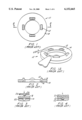
- FIG. 1 is a top view of a conventional direct tension indicating washer 10, commonly referred to as a DTI.
- the direct tension indicating washer 10 includes a series of protuberances 12 formed on a first surface 14. As shown in FIG. 2, corresponding indentations 16 are formed in a second surface 18 of the direct tension indicating washer 10.
- the direct tension indicating washer 10 is manufactured through a stamping operation in which the blank metal washer 10 is placed between a tool 20 and a die 22. Pressure is applied to the tool 20 (e.g. by a press) and a protrusion 24 on the tool 20 creates the protuberance 12, and the corresponding indentation 16, in the direct tension indicating washer 10 as shown in FIG. 4.
- the DTI is manufactured so that when the tightening of the bolt forces the protrusions 12 to compress, or reduce height, sufficiently, the bolt is said to have sufficient tension to meet code requirements. Determination of "sufficient" protrusion compression is accomplished in the field by the attempt to insert a feeler gage of specified thickness (e.g. 0.015") into the residual gap between the underside of the bolt head and the first surface 14 of the DTI.
- FIG. 1A shows a feeler gage being placed on a first surface of a direct tension indicating washer to test bolt tension (the bolt is not shown for clarity).
- the residual DTI gap (the space between the first surface of the direct tension indicating washer and the bottom of the bolt head) is said to be, on average, of dimension less than the thickness of the feeler gage, and is therefore judged acceptable.
- Conventional direct tension indicating washers are manufactured so that surfaces 14 and 18 are parallel and perpendicular to the longitudinal axis of the bolt which they are made to fit on, that is when the bolt is inserted through the inner diameter.
- the conventional direct tension indicating washer when manufactured in relatively small sizes (e.g. for a 1/4 inch diameter bolt), does not function reliably because of the difficulty in accurately using a feeler gauge with such small washers.
- the relatively small direct tension indicating washers cannot accurately indicate low bolt tensions (typically used with small bolts) due to the process of fabricating the protuberances. Accordingly, there is a need in the art for improved direct tension indicating washers.
- One embodiment of the invention is a direct tension indicating washer including a body having an internal opening formed therein and at least one arched tab connected to the body.
- the arched tab has a fixed end integral with the body and a distal end movable with respect to the body.
- Indicia is formed on the arched tab and when the direct tension indicating washer is tensioned, the arched tab is pushed out circumferentially from the body. When the indicia is aligned with a reference (e.g., the periphery of the washer body), this indicates proper tension.
- Another embodiment of the invention is direct tension indicating washer having a body having an internal opening formed therein and at least one arch connected to the body.
- the arch has a first end integral with the body, a second end integral with the body and an intermediate portion between the first end and second end. The intermediate portion is positioned above a top surface of the body.
- the arch is configured to deform through snap-through buckling upon application of a predetermined amount of force to form a deformed arch indicating that a desired amount of bolt tension has been achieved.
- FIG. 1 is a top view of a conventional direct tension indicating and maintaining washer
- FIG. 1A is a perspective view of the use of a feeler gage to test bolt tension
- FIG. 2 is a cross-sectional view of the direct tension indicating and maintaining washer shown in FIG. 1 taken along line 2--2;
- FIGS. 3 and 4 illustrate a process for creating the protuberances/indentations in the conventional direct tension indicating and maintaining washer
- FIG. 5 is a perspective view of a direct tension indicating washer in a first embodiment
- FIG. 6 is top view of a blank used to form the direct tension indicating washer of FIG. 5;
- FIG. 7 is a side view of the blank of FIG. 6;
- FIG. 8 is a top view of a direct tension indicating washer after forming arched tabs
- FIG. 9 depicts the formation of an arched tab
- FIG. 10 is a side view of the direct tension indicating washer of FIG. 8 installed and untensioned;
- FIG. 11 is a side view of the direct tension indicating washer of FIG. 8 installed and tensioned;
- FIG. 12 is a top view of FIG. 11;
- FIG. 13 is a perspective view of a second embodiment of the invention.
- FIG. 14 is a top view of the direct tension indicating washer of FIG. 13;
- FIG. 15 is a side view of the direct tension indicating washer of FIG. 13;
- FIG. 16 is a top view of the direct tension indicating washer of FIG. 13 installed
- FIG. 17 is a side view of the direct tension indicating washer of FIG. 13 installed and tensioned;
- FIGS. 18-20 depict the arch of the direct tension indicating washer of FIG. 13 during installation
- FIG. 21 is a graph of bolt tension versus bolt elongation for the direct tension indicating washer of FIG. 13.
- FIG. 22 is a graph of bolt tension versus bolt rotation for the direct tension indicating washer of FIG. 13.
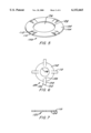
- FIG. 5 is a perspective view of a direct tension indicating washer shown generally at 100.
- the direct tension indicating washer 100 includes a circular body 102 having an outer edge 104. An interior opening 106 is formed in the body 102 which defines an inner edge 108.
- the direct tension indicating washer 100 includes one or more arched tabs 110 each having indica 112. The arched tabs 110 extend above a top surface of the body 102.
- the indicia 112 may be a line or other visible marking.
- the indica 112 may also include a plurality of indicia each indicating a different amount of tension.
- the direct tension indicating washer 100 when the direct tension indicating washer 100 is placed under a bolt head and the bolt is tensioned, the indicia 112 is move radially away from the body 102. When the indicia is aligned with a reference such as the outer edge 104, this indicates that proper bolt tension has been achieved.
- a reference such as the outer edge 104
- FIG. 6 is a top view of a blank 120 which is used to form the direct tension indicating washer 100.
- Blank 120 includes body 102 as described with reference to FIG. 5.
- Tabs 110 are initially coplanar with body 102.
- the blank 120 is stamped out of a material (e.g., metal) to form body 102 and one or more tabs 110.
- tabs 110 have a fixed end 128 where the tab 110 meets body 102.
- Tab 110 also includes two sides 124 and 126 free from body 102 through shearing or cutting body 102.
- the distal end 122 of the tab 110 extends beyond the periphery of body 102.
- the tab 110 is secured to the body 102 at one fixed end 128 but otherwise is free to move relative to body 102.
- the tabs 110 may be positioned equally around the periphery of body 102.
- FIG. 7 is a side view of the blank 120.
- FIG. 8 is a top view of direct tension indicating washer 100.
- the blank 120 is coined such that the tabs 110 are formed into arches and at the same time the indicia 112 is formed on each tab 110.
- FIG. 9 depicts formation of one arched tab.
- the flat tab 110 is compressed between an anvil or tool 130 and a die 132 to form the arch shape.
- the die 132 may include a feature that forms indicia 112 on the top surface of the arched tab 110.
- the distal end 122 may be aligned with the outer edge 104 of body 102.
- a difference between the arched tabs 110 and protuberances formed on conventional direct tension indicating washers is that the conventional protuberances are formed by extrusion whereas the tabs 110 are separate from body 102 by shearing at sides 124 and 126. As described in detail below, this allows the direct tension indicating washer 100 to detect lower bolt tension that conventional direct tension indicating washers.
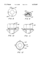
- FIG. 10 depicts the direct tension indicating washer 100 positioned beneath a bolt 140 having bolt head 142.
- the arched tabs 110 are in an original state and the indica 112 are positioned beneath the bolt head 142 and are not visible to the user.
- FIG. 11 depicts the direct tension indicating washer 100 upon tensioning of bolt 140.
- the underside of the bolt head 142 presses against arched tab 110.
- the arched tab 110 is deflected such that the arch is flattened and the distal end 122 moves away from the fixed end 128 and the outer edge 104 of body 102.
- FIG. 10 depicts the direct tension indicating washer 100 positioned beneath a bolt 140 having bolt head 142.
- the arched tabs 110 are in an original state and the indica 112 are positioned beneath the bolt head 142 and are not visible to the user.
- FIG. 11 depicts the direct tension indicating washer 100 upon tensioning of bolt 140.
- the underside of the bolt head 142 presses against arched tab 110.
- arched tab 110 eventually the indicia 112 on the top of arched tab 110 becomes aligned with a reference such as the outer edge 104 of body 102.
- the shape of arched tab 110 is controlled so that the indicia 112 is aligned with a reference such as outer edge 104 upon achieving a predetermined bolt tension.
- the direct tension indicating washer 100 provides several advantages over conventional direct tension indicating washers.
- the direct tension indicating washer 100 is able to record bolt tension lower than that recordable with conventional direct tension indicating washers.
- Conventional direct tension indicating washers form protuberances through extrusion. To compress these conventional protuberances requires relatively large force in the form of high bolt tensions.
- the arched tabs 110 are formed by shearing the body 102 at tab sides 124 and 126. The arched tabs 110 are displaced by deforming or bending tab 110 which requires relatively lower force or bolt tension. Accordingly, the direct tension indicating washer 100 can by used in low tension applications where conventional direct tension indicating washers are impractical.
- the direct tension indicating washer 100 also operates without the use of a feeler gauge. Low bolt tension applications usually use smaller bolts than large bolt tension applications. In these low bolt tension applications, it is difficult to use a feeler gauge given the small dimension of the bolt and bolt head.
- the direct tension indicating washer 100 indicates when the proper bolt tension has been achieved without the use of feeler gauges or other external apparatus.
- the direct tension indicating washer 100 will also maintain bolt tension.
- the shape of the arched tabs 110 will react elastically even under low load situations over a large deflection whereas conventional protuberances are not elastic.
- the elastic nature of the arched tabs 110 maintain tension on the bolt by exerting a force on the underside of the bolt head to help counteract reduction in bolt tension due to vibration, seating of the threads and material deformation of the clamped material.
- the elastic nature of the arched tabs 110 results in the arched tab 110 following the bolt head as the bolt head moves away from the surface of the clamped material.
- FIG. 13 is a perspective view of a direct tension indicating washer 200 in a second embodiment of the invention.
- the direct tension indicating washer 200 includes a circular body 202 having an outer edge 204.
- An interior opening 206 is formed in the body 202 which defines and inner edge 208.
- Positioned about the periphery of body 202 is one or more arches 210.
- Arch 210 is a strip of material having a first end 212 integral with body 202 and a second end 214 integral with body 202.
- An intermediate portion 213 of the arch 210 positioned between the first end 212 and the second end 214 is positioned above the top surface of body 202.
- the arch 210 has a length between ends 212 and 214 that is greater than the length of the outer edge 204 for a similar arc.
- the arch 210 is formed by shearing the body 202 a predetermined distance from the outer edge 204 for a predetermined length.
- the arch 210 is then formed though a stamping process using a tool and die.
- the majority of the arch 210 is positioned above the plane of body 202.
- the arches 210 may be spaced equally around the periphery of body 202.
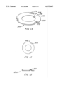
- FIG. 14 is a top view of the direct tension indicating washer 200
- FIG. 15 is a side view of the direct tension indicating washer 200.
- FIG. 16 is a top view of the direct tension indicating washer 200 positioned beneath a bolt 140 having a bolt head 142. As shown in FIG. 16, the arches 210 are positioned beneath the bolt head 142. Direct tension indicating washer 200 indicates bolt tension based on the shape of arches 210. As the bolt 140 is tensioned, the underside of bolt head 142 applies pressure to the peak of arch 210. At a predetermined tension level, the arch 210 will deform to an undulating shape in which the peak of the arch 210 has been inverted and the arch 210 now has two peaks separated by a valley. FIG. 17 depicts an installed direct tension indicating washer 200 in which the desired bolt tension has been achieved and the arch 210 has deformed.
- Snap-through buckling is a known property of arch shapes and the arch compression at which snap-through buckling occurs can be calculated by known mechanics of materials formulas. The amount of compression needed to deform arches 210 is controlled by the number and proportions of the arches. When the arch 210 has deformed, the installer knows that the proper tension has been achieved.
- FIGS. 18-20 depict the deformation of an arch 210.
- the arch 210 is in its original state as shown in FIG. 18 and as tension is applied to the bolt, the arch 210 compresses somewhat as shown in FIG. 19.
- the numbers in FIGS. 18-20 correspond to positions along curves shown in FIGS. 21 and 22.
- bolt tension and bolt elongation increase as the bolt is tightened and force is applied to arch 210.
- the bolt tension shown in FIG. 21 reduces to a minimum bolt tension and the bolt elongation reduces slightly.
- the elastic nature of arch 210 provides force on the underside of bolt head 142 and prevents the bolt tension from going below a minimum level.
- the installer may turn the bolt a predetermined amount (e.g. one rotation) to take up any loss in bolt tension as shown in FIG. 22 as a transition from state 4 to 5.
- the direct tension indicating washer 200 provides advantages over conventional direct tension indicating washers.
- the direct tension indicating washer 200 is able to record bolt tension lower than that recordable with conventional direct tension indicating washers.
- Conventional direct tension indicating washers form protuberances through extrusion. To compress these conventional protuberances requires relatively large force in the form of high bolt tensions.
- the arches 210 are formed by shearing the body 202. The arches 210 are deformed by compressing the arch which requires relatively lower force or bolt tension. Accordingly, the direct tension indicating washer 200 can by used in low tension applications where conventional direct tension indicating washers are impractical.
- the direct tension indicating washer 200 also operates without the use of a feeler gauge. Low bolt tension applications usually use smaller bolts than large bolt tension applications. In these low bolt tension applications, it is difficult to use a feeler gauge given the small dimension of the bolt and bolt head.
- the direct tension indicating washer 200 indicates when the proper bolt tension has been achieved without the use of feeler gauges or other external apparatus. The installer can feel the arch snap-through (transition from FIG. 19 to FIG. 20) and thus knows that a predetermined amount of tension has been achieved.
- the direct tension indicating washer 200 is also useful in applications where a tension threshold should not be exceeded.
- the number and shape of the arches 210 can be controlled to deform upon reaching the maximum tension threshold. As shown in FIG. 21, when the arch deforms or snaps through, some tension is lost. Accordingly, the direct tension indicating washer 200 can ensure that the maximum tension threshold is not exceeded by releasing tension at a certain point.
Abstract
A direct tension indicating washer including a body having an internal opening formed therein and at least one arched tab connected to the body. The arched tab has a fixed end integral with the body and a distal end movable with respect to the body. Indicia is formed on the arched tab and when the direct tension indicating washer is tensioned, the arched tab moves away from the body. Alignment of the indicia with a reference indicates proper tension. Another embodiment of the invention is a direct tension indicating washer having a body having an internal opening formed therein and at least one arch connected to the body. The arch has a first end integral with the body, a second end integral with the body and an intermediate portion between the first end and second end. The intermediate portion is positioned above a top surface of the body. The arch is configured to deform upon application of a predetermined amount of force to form a deformed arch indicating that a predetermined amount of bolt tension has been achieved.
Description
The invention relates in general to direct tension indicating washers and in particular to direct tension indicating washers that self indicate when the proper bolt tension has been achieved.
High strength metal bolts, along with their corresponding nuts, when used in metal connections, are almost always intended to be installed so that they are "tensioned." The "tensioning" is usually accomplished by turning the nut relative to the bolt a specified amount of rotation or until a certain torque resistance has been reached. The tension in the bolt stretches the bolt and compresses the connection plates between the bolt head and nut so the connection plates do not slip relative to each other. It is this slip resistance which holds structures such as bridges and buildings together.
FIG. 1 is a top view of a conventional direct tension indicating washer 10, commonly referred to as a DTI. The direct tension indicating washer 10 includes a series of protuberances 12 formed on a first surface 14. As shown in FIG. 2, corresponding indentations 16 are formed in a second surface 18 of the direct tension indicating washer 10. As shown in FIGS. 3 and 4, the direct tension indicating washer 10 is manufactured through a stamping operation in which the blank metal washer 10 is placed between a tool 20 and a die 22. Pressure is applied to the tool 20 (e.g. by a press) and a protrusion 24 on the tool 20 creates the protuberance 12, and the corresponding indentation 16, in the direct tension indicating washer 10 as shown in FIG. 4.
The DTI is manufactured so that when the tightening of the bolt forces the protrusions 12 to compress, or reduce height, sufficiently, the bolt is said to have sufficient tension to meet code requirements. Determination of "sufficient" protrusion compression is accomplished in the field by the attempt to insert a feeler gage of specified thickness (e.g. 0.015") into the residual gap between the underside of the bolt head and the first surface 14 of the DTI. FIG. 1A shows a feeler gage being placed on a first surface of a direct tension indicating washer to test bolt tension (the bolt is not shown for clarity). If the attempt to insert the feeler gage is unsuccessful, that is, the inspector cannot insert the feeler gage into the gap half way radially around the DTI circumference between the DTI protuberances, the residual DTI gap (the space between the first surface of the direct tension indicating washer and the bottom of the bolt head) is said to be, on average, of dimension less than the thickness of the feeler gage, and is therefore judged acceptable. Conventional direct tension indicating washers are manufactured so that surfaces 14 and 18 are parallel and perpendicular to the longitudinal axis of the bolt which they are made to fit on, that is when the bolt is inserted through the inner diameter.
Conventional direct tension indicating washers, though well suited for their intended purposes, have several drawbacks. First, the process of attempting to insert the feeler gage into the DTI gap is time consuming and must be done after the bolt installer has stopped the tightening process. Second, over time, bolt tension declines as the bolt/nut threads seat into the mating steel surfaces and as external loads shake the connections and try to pry the bolt/nut apart. This problem is especially prominent in connections that are subject to vibration such as bridges, structures subject to earthquakes, connections supporting moving cranes and other equipment, etc. As the bolt tension declines, so does the clamping force and the capacity to carry external loads by resistance to slip. The conventional direct tension indicating washer 10 is flat and has the disadvantage that, after bolt installation, the protrusions 12 are essentially flattened inelastically and will not spring back to their original positions if the bolt begins to loose tension.
In addition, the conventional direct tension indicating washer, when manufactured in relatively small sizes (e.g. for a 1/4 inch diameter bolt), does not function reliably because of the difficulty in accurately using a feeler gauge with such small washers. Also, the relatively small direct tension indicating washers cannot accurately indicate low bolt tensions (typically used with small bolts) due to the process of fabricating the protuberances. Accordingly, there is a need in the art for improved direct tension indicating washers.
The above-discussed and other drawbacks and deficiencies of the prior art are overcome or alleviated by the direct tension indicating washers of the present invention. One embodiment of the invention is a direct tension indicating washer including a body having an internal opening formed therein and at least one arched tab connected to the body. The arched tab has a fixed end integral with the body and a distal end movable with respect to the body. Indicia is formed on the arched tab and when the direct tension indicating washer is tensioned, the arched tab is pushed out circumferentially from the body. When the indicia is aligned with a reference (e.g., the periphery of the washer body), this indicates proper tension.
Another embodiment of the invention is direct tension indicating washer having a body having an internal opening formed therein and at least one arch connected to the body. The arch has a first end integral with the body, a second end integral with the body and an intermediate portion between the first end and second end. The intermediate portion is positioned above a top surface of the body. The arch is configured to deform through snap-through buckling upon application of a predetermined amount of force to form a deformed arch indicating that a desired amount of bolt tension has been achieved.
The above-discussed and other features and advantages of the present invention will be appreciated and understood by those skilled in the art from the following detailed description and drawings.
Referring now to the drawings wherein like elements are numbered alike in the several FIGURES:
FIG. 1 is a top view of a conventional direct tension indicating and maintaining washer;
FIG. 1A is a perspective view of the use of a feeler gage to test bolt tension;
FIG. 2 is a cross-sectional view of the direct tension indicating and maintaining washer shown in FIG. 1 taken along line 2--2;
FIGS. 3 and 4 illustrate a process for creating the protuberances/indentations in the conventional direct tension indicating and maintaining washer;
FIG. 5 is a perspective view of a direct tension indicating washer in a first embodiment;
FIG. 6 is top view of a blank used to form the direct tension indicating washer of FIG. 5;
FIG. 7 is a side view of the blank of FIG. 6;
FIG. 8 is a top view of a direct tension indicating washer after forming arched tabs;
FIG. 9 depicts the formation of an arched tab;
FIG. 10 is a side view of the direct tension indicating washer of FIG. 8 installed and untensioned;
FIG. 11 is a side view of the direct tension indicating washer of FIG. 8 installed and tensioned;
FIG. 12 is a top view of FIG. 11;
FIG. 13 is a perspective view of a second embodiment of the invention;
FIG. 14 is a top view of the direct tension indicating washer of FIG. 13;
FIG. 15 is a side view of the direct tension indicating washer of FIG. 13;
FIG. 16 is a top view of the direct tension indicating washer of FIG. 13 installed;
FIG. 17 is a side view of the direct tension indicating washer of FIG. 13 installed and tensioned;
FIGS. 18-20 depict the arch of the direct tension indicating washer of FIG. 13 during installation;
FIG. 21 is a graph of bolt tension versus bolt elongation for the direct tension indicating washer of FIG. 13; and
FIG. 22 is a graph of bolt tension versus bolt rotation for the direct tension indicating washer of FIG. 13.
FIG. 5 is a perspective view of a direct tension indicating washer shown generally at 100. The direct tension indicating washer 100 includes a circular body 102 having an outer edge 104. An interior opening 106 is formed in the body 102 which defines an inner edge 108. The direct tension indicating washer 100 includes one or more arched tabs 110 each having indica 112. The arched tabs 110 extend above a top surface of the body 102. The indicia 112 may be a line or other visible marking. The indica 112 may also include a plurality of indicia each indicating a different amount of tension. As described herein, when the direct tension indicating washer 100 is placed under a bolt head and the bolt is tensioned, the indicia 112 is move radially away from the body 102. When the indicia is aligned with a reference such as the outer edge 104, this indicates that proper bolt tension has been achieved. The process of forming the direct tension indicating washer 100 will now be described.
FIG. 6 is a top view of a blank 120 which is used to form the direct tension indicating washer 100. Blank 120 includes body 102 as described with reference to FIG. 5. Tabs 110 are initially coplanar with body 102. The blank 120 is stamped out of a material (e.g., metal) to form body 102 and one or more tabs 110. As shown in FIG. 6, tabs 110 have a fixed end 128 where the tab 110 meets body 102. Tab 110 also includes two sides 124 and 126 free from body 102 through shearing or cutting body 102. The distal end 122 of the tab 110 extends beyond the periphery of body 102. Thus, the tab 110 is secured to the body 102 at one fixed end 128 but otherwise is free to move relative to body 102. The tabs 110 may be positioned equally around the periphery of body 102. FIG. 7 is a side view of the blank 120.
FIG. 8 is a top view of direct tension indicating washer 100. The blank 120 is coined such that the tabs 110 are formed into arches and at the same time the indicia 112 is formed on each tab 110. FIG. 9 depicts formation of one arched tab. The flat tab 110 is compressed between an anvil or tool 130 and a die 132 to form the arch shape. The die 132 may include a feature that forms indicia 112 on the top surface of the arched tab 110. The distal end 122 may be aligned with the outer edge 104 of body 102. A difference between the arched tabs 110 and protuberances formed on conventional direct tension indicating washers is that the conventional protuberances are formed by extrusion whereas the tabs 110 are separate from body 102 by shearing at sides 124 and 126. As described in detail below, this allows the direct tension indicating washer 100 to detect lower bolt tension that conventional direct tension indicating washers.
FIG. 10 depicts the direct tension indicating washer 100 positioned beneath a bolt 140 having bolt head 142. In an untensioned state, the arched tabs 110 are in an original state and the indica 112 are positioned beneath the bolt head 142 and are not visible to the user. FIG. 11 depicts the direct tension indicating washer 100 upon tensioning of bolt 140. As shown in FIG. 11, as the bolt 140 is tensioned, the underside of the bolt head 142 presses against arched tab 110. The arched tab 110 is deflected such that the arch is flattened and the distal end 122 moves away from the fixed end 128 and the outer edge 104 of body 102. As shown in FIG. 12, eventually the indicia 112 on the top of arched tab 110 becomes aligned with a reference such as the outer edge 104 of body 102. The shape of arched tab 110 is controlled so that the indicia 112 is aligned with a reference such as outer edge 104 upon achieving a predetermined bolt tension.
The direct tension indicating washer 100 provides several advantages over conventional direct tension indicating washers. The direct tension indicating washer 100 is able to record bolt tension lower than that recordable with conventional direct tension indicating washers. Conventional direct tension indicating washers form protuberances through extrusion. To compress these conventional protuberances requires relatively large force in the form of high bolt tensions. By contrast, the arched tabs 110 are formed by shearing the body 102 at tab sides 124 and 126. The arched tabs 110 are displaced by deforming or bending tab 110 which requires relatively lower force or bolt tension. Accordingly, the direct tension indicating washer 100 can by used in low tension applications where conventional direct tension indicating washers are impractical.
The direct tension indicating washer 100 also operates without the use of a feeler gauge. Low bolt tension applications usually use smaller bolts than large bolt tension applications. In these low bolt tension applications, it is difficult to use a feeler gauge given the small dimension of the bolt and bolt head. The direct tension indicating washer 100 indicates when the proper bolt tension has been achieved without the use of feeler gauges or other external apparatus.
The direct tension indicating washer 100 will also maintain bolt tension. The shape of the arched tabs 110 will react elastically even under low load situations over a large deflection whereas conventional protuberances are not elastic. The elastic nature of the arched tabs 110 maintain tension on the bolt by exerting a force on the underside of the bolt head to help counteract reduction in bolt tension due to vibration, seating of the threads and material deformation of the clamped material. The elastic nature of the arched tabs 110 results in the arched tab 110 following the bolt head as the bolt head moves away from the surface of the clamped material.
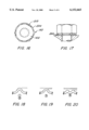
FIG. 13 is a perspective view of a direct tension indicating washer 200 in a second embodiment of the invention. The direct tension indicating washer 200 includes a circular body 202 having an outer edge 204. An interior opening 206 is formed in the body 202 which defines and inner edge 208. Positioned about the periphery of body 202 is one or more arches 210. Arch 210 is a strip of material having a first end 212 integral with body 202 and a second end 214 integral with body 202. An intermediate portion 213 of the arch 210 positioned between the first end 212 and the second end 214 is positioned above the top surface of body 202. The arch 210 has a length between ends 212 and 214 that is greater than the length of the outer edge 204 for a similar arc. The arch 210 is formed by shearing the body 202 a predetermined distance from the outer edge 204 for a predetermined length. The arch 210 is then formed though a stamping process using a tool and die. The majority of the arch 210 is positioned above the plane of body 202. The arches 210 may be spaced equally around the periphery of body 202. FIG. 14 is a top view of the direct tension indicating washer 200 and FIG. 15 is a side view of the direct tension indicating washer 200.
FIG. 16 is a top view of the direct tension indicating washer 200 positioned beneath a bolt 140 having a bolt head 142. As shown in FIG. 16, the arches 210 are positioned beneath the bolt head 142. Direct tension indicating washer 200 indicates bolt tension based on the shape of arches 210. As the bolt 140 is tensioned, the underside of bolt head 142 applies pressure to the peak of arch 210. At a predetermined tension level, the arch 210 will deform to an undulating shape in which the peak of the arch 210 has been inverted and the arch 210 now has two peaks separated by a valley. FIG. 17 depicts an installed direct tension indicating washer 200 in which the desired bolt tension has been achieved and the arch 210 has deformed.
This type of deformation may be referred to as "snap-through buckling" and is also known as oil canning. Snap-through buckling is a known property of arch shapes and the arch compression at which snap-through buckling occurs can be calculated by known mechanics of materials formulas. The amount of compression needed to deform arches 210 is controlled by the number and proportions of the arches. When the arch 210 has deformed, the installer knows that the proper tension has been achieved.
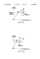
FIGS. 18-20 depict the deformation of an arch 210. Initially, the arch 210 is in its original state as shown in FIG. 18 and as tension is applied to the bolt, the arch 210 compresses somewhat as shown in FIG. 19. The numbers in FIGS. 18-20 correspond to positions along curves shown in FIGS. 21 and 22. As shown in FIGS. 21 and 22, bolt tension and bolt elongation increase as the bolt is tightened and force is applied to arch 210. When the arch 210 deforms or snaps through as shown in FIG. 20, the bolt tension shown in FIG. 21 reduces to a minimum bolt tension and the bolt elongation reduces slightly. The elastic nature of arch 210 provides force on the underside of bolt head 142 and prevents the bolt tension from going below a minimum level. To increase bolt tension after the deformation of arch 210, the installer may turn the bolt a predetermined amount (e.g. one rotation) to take up any loss in bolt tension as shown in FIG. 22 as a transition from state 4 to 5.
The direct tension indicating washer 200 provides advantages over conventional direct tension indicating washers. The direct tension indicating washer 200 is able to record bolt tension lower than that recordable with conventional direct tension indicating washers. Conventional direct tension indicating washers form protuberances through extrusion. To compress these conventional protuberances requires relatively large force in the form of high bolt tensions. By contrast, the arches 210 are formed by shearing the body 202. The arches 210 are deformed by compressing the arch which requires relatively lower force or bolt tension. Accordingly, the direct tension indicating washer 200 can by used in low tension applications where conventional direct tension indicating washers are impractical.
The direct tension indicating washer 200 also operates without the use of a feeler gauge. Low bolt tension applications usually use smaller bolts than large bolt tension applications. In these low bolt tension applications, it is difficult to use a feeler gauge given the small dimension of the bolt and bolt head. The direct tension indicating washer 200 indicates when the proper bolt tension has been achieved without the use of feeler gauges or other external apparatus. The installer can feel the arch snap-through (transition from FIG. 19 to FIG. 20) and thus knows that a predetermined amount of tension has been achieved.
The direct tension indicating washer 200 is also useful in applications where a tension threshold should not be exceeded. The number and shape of the arches 210 can be controlled to deform upon reaching the maximum tension threshold. As shown in FIG. 21, when the arch deforms or snaps through, some tension is lost. Accordingly, the direct tension indicating washer 200 can ensure that the maximum tension threshold is not exceeded by releasing tension at a certain point.
While preferred embodiments have been shown and described, various modifications and substitutions may be made thereto without departing from the spirit and scope of the invention. Accordingly, it is to be understood that the present invention has been described by way of illustration and not limitation.
Claims (13)
1. A direct tension indicating washer comprising:
a body having an internal opening formed therein; and
at least one arched tab connected to said body, said arched tab having a fixed end integral with said body and a distal end movable with respect to said body; and
indicia formed on said at least one arched tab.
2. The direct tension indicating washer of claim 1 wherein:
said at least one arched tab includes a plurality of arched tabs.
3. The direct tension indicating washer of claim 1 wherein:
said indicia is a line.
4. The direct tension indicating washer of claim 3 wherein:
said indicia is a plurality of indicia.
5. The direct tension indicating washer of claim 1 wherein:
said arched tab is configured such that said indicia is aligned with a reference upon achieving a predetermined bolt tension.
6. The direct tension indicating washer of claim 5 wherein:
said reference is an outer edge of said body.
7. The direct tension indicating washer of claim 1 wherein said arched tab extends in a radial direction and said distal end extends beyond an outer edge of said body upon achieving a predetermined bolt tension.
8. A direct tension indicating washer comprising:
a body having an internal opening formed therein; and
at least one arch connected to said body, said arch having a first end integral with said body, a second end integral with said body and an intermediate portion between the first end and second end, said intermediate portion extending along a length of said arch positioned above a top surface of said body;
wherein there are no slits cut transversely into said arch and said arch is configured to deform upon application of a predetermined amount of force to form a deformed arch.
9. The direct tension indicating washer of claim 8 wherein:
said at least one arch includes a plurality of arches.
10. The direct tension indicating washer of claim 9 wherein:
said plurality of arches are equally spaced around said body.
11. The direct tension indicating washer of claim 8 wherein:
said deformed arch includes two peaks separated by a valley.
12. A direct tension indicating washer comprising
a body having an internal opening formed therein; and
at least one arch connected to said body, said arch having a first end integral with said body, a second end integral with said body and an intermediate portion between the first end and second end, said intermediate portion positioned above a tope surface of said body;
wherein said arch is configured to deform upon application of a predetermined amount of force to form a deformed arch, said deformed arch includes two peaks separated by a valley.
13. A direct tension indicating washer formed by forming at least one arch by shearing a flat body along at least one shear line for each arch, said body separating at said shear line forming an aperture between said body and said arch along said shear line; each said arch being connected only at both ends to said body and extending away from a plane in which said body lies.
Priority Applications (1)
| Application Number | Priority Date | Filing Date | Title |
|---|---|---|---|
| US09/377,994 US6152665A (en) | 1999-08-20 | 1999-08-20 | Direct tension indicating washers |
Applications Claiming Priority (1)
| Application Number | Priority Date | Filing Date | Title |
|---|---|---|---|
| US09/377,994 US6152665A (en) | 1999-08-20 | 1999-08-20 | Direct tension indicating washers |
Publications (1)
| Publication Number | Publication Date |
|---|---|
| US6152665A true US6152665A (en) | 2000-11-28 |
Family
ID=23491306
Family Applications (1)
| Application Number | Title | Priority Date | Filing Date |
|---|---|---|---|
| US09/377,994 Expired - Fee Related US6152665A (en) | 1999-08-20 | 1999-08-20 | Direct tension indicating washers |
Country Status (1)
| Country | Link |
|---|---|
| US (1) | US6152665A (en) |
Cited By (22)
| Publication number | Priority date | Publication date | Assignee | Title |
|---|---|---|---|---|
| US20030047985A1 (en) * | 2001-09-10 | 2003-03-13 | Stiffler Stephen P. | Embossed washer |
| US20040046099A1 (en) * | 2002-09-06 | 2004-03-11 | Honda Giken Kogyo Kabushiki Kaisha | Power unit mount structure for vehicles |
| US6729819B2 (en) | 2002-07-03 | 2004-05-04 | Applied Bolting Technology Products, Inc. | Bolt lubricating device and method |
| US20050001382A1 (en) * | 2003-07-02 | 2005-01-06 | Fitzsimons Keith Bryden | Compliant spacer |
| US20050091774A1 (en) * | 2003-11-05 | 2005-05-05 | Biggs Blyth S. | Mop handle connector |
| DE102005021868A1 (en) * | 2005-05-11 | 2006-12-07 | Zf Friedrichshafen Ag | Shaft to collar connection e.g. for adjusting defined preload force, has shaft nut which covers plastic ductile element with defined cross section in axial direction |
| US20090232614A1 (en) * | 2008-03-17 | 2009-09-17 | Ivan Wayne Wallace | Direct Tension Indicating Washer Having Enhanced Emission Of Indicating Material |
| US20110123288A1 (en) * | 2009-05-19 | 2011-05-26 | Ivan Wayne Wallace | Direct Tension Multi-Color Indicating Washers |
| US20110280682A1 (en) * | 2010-05-14 | 2011-11-17 | Honda Motor Co., Ltd. | Flange fastening structure |
| US20140004738A1 (en) * | 2011-01-03 | 2014-01-02 | Wolfgang B. Thoerner | Pole terminal |
| US20140357120A1 (en) * | 2011-12-27 | 2014-12-04 | Joshua Blake | Coaxial connector with grommet biasing for enhanced continuity |
| US20150162675A1 (en) * | 2011-12-27 | 2015-06-11 | Perfectvision Manufacturing, Inc. | Enhanced Continuity Connector |
| US20150202016A1 (en) * | 2012-08-31 | 2015-07-23 | Sanofi-Aventis Deutschland Gmbh | Impact-Resistant Fastening Assembly for a Medical Device |
| US20150267731A1 (en) * | 2014-03-18 | 2015-09-24 | Robert E. Stewart | Direct Tension Indicator Plate and Assembly |
| DE202015105195U1 (en) | 2015-10-01 | 2015-12-02 | Thomas Volborth | Device for controlling screw connections |
| EP3150868A1 (en) | 2015-10-01 | 2017-04-05 | Thomas Volborth | Device for controlling of screwed connections |
| US9863457B2 (en) | 2015-11-11 | 2018-01-09 | Turnasure Llc | Direct tension indicating washer with offset protuberances and indentations |
| ES2699362A1 (en) * | 2017-04-11 | 2019-02-08 | Turnasure Llc | A DIRECT TENSION INDICATOR WASHER (Machine-translation by Google Translate, not legally binding) |
| US10280963B2 (en) * | 2014-01-23 | 2019-05-07 | Harvel K. Crumley | System and method for retrofitting walls with retaining ties |
| JP2019078404A (en) * | 2017-10-24 | 2019-05-23 | ヒルティ アクチエンゲゼルシャフト | Fastener coupler including engagement indicator |
| ES2728719A1 (en) * | 2016-05-18 | 2019-10-28 | Applied Bolting Tech | Direct tension indicating apparatus |
| US20210040980A1 (en) * | 2018-04-20 | 2021-02-11 | Spieth-Maschinenelemente Gmbh & Co. Kg | Fixing device |
Citations (24)
| Publication number | Priority date | Publication date | Assignee | Title |
|---|---|---|---|---|
| US2191101A (en) * | 1939-01-23 | 1940-02-20 | Domnic V Stellin | Lock washer |
| US2274010A (en) * | 1939-12-16 | 1942-02-24 | Domnic V Stellin | Lock washer |
| US2476561A (en) * | 1945-03-17 | 1949-07-19 | Pedersen Norman Lind | Locking device |
| US2781687A (en) * | 1954-02-24 | 1957-02-19 | Chrysler Corp | Assembly comprising calibrated bolt and calibrated deformable conical washer |
| US2850937A (en) * | 1955-04-28 | 1958-09-09 | Eldon K Ralston | Snap type bolt tension indicator |
| US2943528A (en) * | 1957-10-29 | 1960-07-05 | Virgil A Curry | Mine roof stress indicating bolt |
| US3187621A (en) * | 1962-12-14 | 1965-06-08 | Cooper & Turner Ltd | Fastener assembly and pre-load indicating washer therefor |
| US3304827A (en) * | 1965-10-13 | 1967-02-21 | Clarence C Bush | Spring type torque indicating lock washer |
| US3476009A (en) * | 1967-04-28 | 1969-11-04 | Teledyne Inc | Spring washer |
| GB1184033A (en) * | 1967-02-16 | 1970-03-11 | Daimler Benz Ag | Improvements relating to Washers for Screw Connections |
| US3948141A (en) * | 1974-08-20 | 1976-04-06 | Katsumi Shinjo | Load indicating washer |
| JPS529757A (en) * | 1975-07-15 | 1977-01-25 | Nippon Steel Corp | Clamping method of bolt and its washer |
| US4020734A (en) * | 1975-11-26 | 1977-05-03 | Star Expansion Industries Corporation | Tension indicator for fastener means |
| US4072081A (en) * | 1975-11-14 | 1978-02-07 | Illinois Tool Works Inc. | Tension indicating washer unit |
| US4149446A (en) * | 1977-12-01 | 1979-04-17 | Bethlehem Steel Corporation | Load indicator washer |
| US4322193A (en) * | 1980-06-09 | 1982-03-30 | Stahl Keith E | Tension gauge |
| US4347024A (en) * | 1980-08-22 | 1982-08-31 | Eaton Corporation | Tension indicating and lock cone washer |
| US4498825A (en) * | 1982-09-27 | 1985-02-12 | Russell, Burdsall & Ward Corporation | Load indicating flange |
| US4793757A (en) * | 1987-05-15 | 1988-12-27 | Buell Industries, Inc. | Finishing washer |
| US5015132A (en) * | 1990-05-15 | 1991-05-14 | J & M Turner Inc. | Direct tension indicator washer |
| US5056975A (en) * | 1989-05-31 | 1991-10-15 | Trw Steering & Industrial Products (Japan) Co. Ltd. | Elastically compressible conical lock washer |
| US5370483A (en) * | 1993-06-24 | 1994-12-06 | J & M Turner, Inc. | Direct tension indicator washer |
| US5667346A (en) * | 1996-02-06 | 1997-09-16 | F. Jonathan M. Turner | Direct tension indicator washer |
| US5769581A (en) * | 1997-02-21 | 1998-06-23 | Applied Bolting Technology Products, Inc. | Direct tension indicating washers |
-
1999
- 1999-08-20 US US09/377,994 patent/US6152665A/en not_active Expired - Fee Related
Patent Citations (25)
| Publication number | Priority date | Publication date | Assignee | Title |
|---|---|---|---|---|
| US2191101A (en) * | 1939-01-23 | 1940-02-20 | Domnic V Stellin | Lock washer |
| US2274010A (en) * | 1939-12-16 | 1942-02-24 | Domnic V Stellin | Lock washer |
| US2476561A (en) * | 1945-03-17 | 1949-07-19 | Pedersen Norman Lind | Locking device |
| US2781687A (en) * | 1954-02-24 | 1957-02-19 | Chrysler Corp | Assembly comprising calibrated bolt and calibrated deformable conical washer |
| US2850937A (en) * | 1955-04-28 | 1958-09-09 | Eldon K Ralston | Snap type bolt tension indicator |
| US2943528A (en) * | 1957-10-29 | 1960-07-05 | Virgil A Curry | Mine roof stress indicating bolt |
| US3187621A (en) * | 1962-12-14 | 1965-06-08 | Cooper & Turner Ltd | Fastener assembly and pre-load indicating washer therefor |
| US3304827A (en) * | 1965-10-13 | 1967-02-21 | Clarence C Bush | Spring type torque indicating lock washer |
| GB1184033A (en) * | 1967-02-16 | 1970-03-11 | Daimler Benz Ag | Improvements relating to Washers for Screw Connections |
| US3476009A (en) * | 1967-04-28 | 1969-11-04 | Teledyne Inc | Spring washer |
| US3948141A (en) * | 1974-08-20 | 1976-04-06 | Katsumi Shinjo | Load indicating washer |
| JPS529757A (en) * | 1975-07-15 | 1977-01-25 | Nippon Steel Corp | Clamping method of bolt and its washer |
| US4072081A (en) * | 1975-11-14 | 1978-02-07 | Illinois Tool Works Inc. | Tension indicating washer unit |
| US4020734A (en) * | 1975-11-26 | 1977-05-03 | Star Expansion Industries Corporation | Tension indicator for fastener means |
| US4149446A (en) * | 1977-12-01 | 1979-04-17 | Bethlehem Steel Corporation | Load indicator washer |
| US4322193A (en) * | 1980-06-09 | 1982-03-30 | Stahl Keith E | Tension gauge |
| US4347024A (en) * | 1980-08-22 | 1982-08-31 | Eaton Corporation | Tension indicating and lock cone washer |
| US4498825A (en) * | 1982-09-27 | 1985-02-12 | Russell, Burdsall & Ward Corporation | Load indicating flange |
| US4793757A (en) * | 1987-05-15 | 1988-12-27 | Buell Industries, Inc. | Finishing washer |
| US5056975A (en) * | 1989-05-31 | 1991-10-15 | Trw Steering & Industrial Products (Japan) Co. Ltd. | Elastically compressible conical lock washer |
| US5015132A (en) * | 1990-05-15 | 1991-05-14 | J & M Turner Inc. | Direct tension indicator washer |
| US5370483A (en) * | 1993-06-24 | 1994-12-06 | J & M Turner, Inc. | Direct tension indicator washer |
| US5667346A (en) * | 1996-02-06 | 1997-09-16 | F. Jonathan M. Turner | Direct tension indicator washer |
| US5769581A (en) * | 1997-02-21 | 1998-06-23 | Applied Bolting Technology Products, Inc. | Direct tension indicating washers |
| US5931618A (en) * | 1997-02-21 | 1999-08-03 | Applied Bolting Technology Products, Inc. | Direct tension indicating washers |
Cited By (35)
| Publication number | Priority date | Publication date | Assignee | Title |
|---|---|---|---|---|
| US6824225B2 (en) * | 2001-09-10 | 2004-11-30 | Kennametal Inc. | Embossed washer |
| US20030047985A1 (en) * | 2001-09-10 | 2003-03-13 | Stiffler Stephen P. | Embossed washer |
| US6729819B2 (en) | 2002-07-03 | 2004-05-04 | Applied Bolting Technology Products, Inc. | Bolt lubricating device and method |
| US6877710B2 (en) * | 2002-09-06 | 2005-04-12 | Honda Giken Kogyo Kabushiki Kaisha | Power unit mount structure vehicles |
| US20040046099A1 (en) * | 2002-09-06 | 2004-03-11 | Honda Giken Kogyo Kabushiki Kaisha | Power unit mount structure for vehicles |
| US7182325B2 (en) * | 2003-07-02 | 2007-02-27 | Westland Helicopters Limited | Compliant spacer |
| US20050001382A1 (en) * | 2003-07-02 | 2005-01-06 | Fitzsimons Keith Bryden | Compliant spacer |
| US20050091774A1 (en) * | 2003-11-05 | 2005-05-05 | Biggs Blyth S. | Mop handle connector |
| DE102005021868A1 (en) * | 2005-05-11 | 2006-12-07 | Zf Friedrichshafen Ag | Shaft to collar connection e.g. for adjusting defined preload force, has shaft nut which covers plastic ductile element with defined cross section in axial direction |
| US20090232614A1 (en) * | 2008-03-17 | 2009-09-17 | Ivan Wayne Wallace | Direct Tension Indicating Washer Having Enhanced Emission Of Indicating Material |
| US7857562B2 (en) | 2008-03-17 | 2010-12-28 | Ivan Wayne Wallace | Direct tension indicating washer having enhanced emission of indicating material |
| US20110123288A1 (en) * | 2009-05-19 | 2011-05-26 | Ivan Wayne Wallace | Direct Tension Multi-Color Indicating Washers |
| US8382409B2 (en) | 2009-05-19 | 2013-02-26 | Applied Bolting Technology Products, Inc. | Direct tension multi-color indicating washers |
| US20110280682A1 (en) * | 2010-05-14 | 2011-11-17 | Honda Motor Co., Ltd. | Flange fastening structure |
| US9127628B2 (en) * | 2010-05-14 | 2015-09-08 | Honda Motor Co., Ltd. | Flange fastening structure |
| US20140004738A1 (en) * | 2011-01-03 | 2014-01-02 | Wolfgang B. Thoerner | Pole terminal |
| US20150162675A1 (en) * | 2011-12-27 | 2015-06-11 | Perfectvision Manufacturing, Inc. | Enhanced Continuity Connector |
| US9362634B2 (en) * | 2011-12-27 | 2016-06-07 | Perfectvision Manufacturing, Inc. | Enhanced continuity connector |
| US20140357120A1 (en) * | 2011-12-27 | 2014-12-04 | Joshua Blake | Coaxial connector with grommet biasing for enhanced continuity |
| US9564694B2 (en) * | 2011-12-27 | 2017-02-07 | Perfectvision Manufacturing, Inc. | Coaxial connector with grommet biasing for enhanced continuity |
| US20150202016A1 (en) * | 2012-08-31 | 2015-07-23 | Sanofi-Aventis Deutschland Gmbh | Impact-Resistant Fastening Assembly for a Medical Device |
| US10280963B2 (en) * | 2014-01-23 | 2019-05-07 | Harvel K. Crumley | System and method for retrofitting walls with retaining ties |
| US9239071B2 (en) * | 2014-03-18 | 2016-01-19 | Robert E. Stewart | Direct tension indicator plate and assembly |
| US9970471B2 (en) * | 2014-03-18 | 2018-05-15 | Robert E. Stewart | Direct tension indicator plate and assembly |
| US20150267731A1 (en) * | 2014-03-18 | 2015-09-24 | Robert E. Stewart | Direct Tension Indicator Plate and Assembly |
| DE202015105195U1 (en) | 2015-10-01 | 2015-12-02 | Thomas Volborth | Device for controlling screw connections |
| EP3150868A1 (en) | 2015-10-01 | 2017-04-05 | Thomas Volborth | Device for controlling of screwed connections |
| WO2017054946A1 (en) | 2015-10-01 | 2017-04-06 | Thomas Volborth | Device for checking threaded connections |
| US9863457B2 (en) | 2015-11-11 | 2018-01-09 | Turnasure Llc | Direct tension indicating washer with offset protuberances and indentations |
| ES2728719A1 (en) * | 2016-05-18 | 2019-10-28 | Applied Bolting Tech | Direct tension indicating apparatus |
| ES2699362A1 (en) * | 2017-04-11 | 2019-02-08 | Turnasure Llc | A DIRECT TENSION INDICATOR WASHER (Machine-translation by Google Translate, not legally binding) |
| US10738817B2 (en) | 2017-04-11 | 2020-08-11 | Turnasure Llc | Self-indicating direct tension indicator |
| JP2019078404A (en) * | 2017-10-24 | 2019-05-23 | ヒルティ アクチエンゲゼルシャフト | Fastener coupler including engagement indicator |
| US20210040980A1 (en) * | 2018-04-20 | 2021-02-11 | Spieth-Maschinenelemente Gmbh & Co. Kg | Fixing device |
| US11808295B2 (en) * | 2018-04-20 | 2023-11-07 | Spieth-Maschinenelemente Gmbh & Co. Kg | Fixing device |
Similar Documents
| Publication | Publication Date | Title |
|---|---|---|
| US6152665A (en) | Direct tension indicating washers | |
| US5931618A (en) | Direct tension indicating washers | |
| AU650269B2 (en) | Direct tension indicator washer | |
| EP0200358B1 (en) | Sealing washers | |
| US6135687A (en) | Direct tension indicator for embedded anchor members | |
| AU2007284893B2 (en) | Load indicating fastener and method of manufacture | |
| US5803692A (en) | Pushnut for use in conjunction with a cylindrical shaft having a pair of opposed flat surfaces | |
| CA2519654A1 (en) | Torque resistant fastening element | |
| JP3212887B2 (en) | Building blind bolts | |
| KR20120101465A (en) | Nut with lug flare | |
| JPS6025648B2 (en) | Helical conical spring lock washer | |
| EP1223355A1 (en) | Fastener panel mounting system | |
| JP4519045B2 (en) | Screw locking structure | |
| US5667346A (en) | Direct tension indicator washer | |
| US6799929B2 (en) | Method of attaching a plate to a rod and assembly | |
| CN101438066A (en) | Pierce nut and use thereof | |
| JPH09189318A (en) | Fastener, manufacture of fastener, fastener-installation member assembly, installation method of fastener to installation member, and die button for installation of fastener to installation member | |
| US7581753B2 (en) | Retaining clamp | |
| EP1584826B1 (en) | Threaded insert with knurl | |
| US20090110510A1 (en) | Washer including protrusions for use in a fastener assembly | |
| EP3715648B1 (en) | Clamping system and method for prestressing a fastening element | |
| EP0171348A1 (en) | Fastener for thin material and method for installing same | |
| JP4834027B2 (en) | Caulking screw, caulking screw manufacturing method, and caulking screw joining structure | |
| JP7079921B2 (en) | Loosening washer | |
| RU43325U1 (en) | KOMARNITSKY washer |
Legal Events
| Date | Code | Title | Description |
|---|---|---|---|
| AS | Assignment |
Owner name: APPLIED BOLTING TECHNOLOGY PRODUCTS, INC., VERMONT Free format text: ASSIGNMENT OF ASSIGNORS INTEREST;ASSIGNORS:WALLACE, IVAN WAYNE;HERR, JOHN A.;REEL/FRAME:010342/0974 Effective date: 19991005 |
|
| FEPP | Fee payment procedure |
Free format text: PAYOR NUMBER ASSIGNED (ORIGINAL EVENT CODE: ASPN); ENTITY STATUS OF PATENT OWNER: SMALL ENTITY |
|
| FPAY | Fee payment |
Year of fee payment: 4 |
|
| REMI | Maintenance fee reminder mailed | ||
| LAPS | Lapse for failure to pay maintenance fees | ||
| STCH | Information on status: patent discontinuation |
Free format text: PATENT EXPIRED DUE TO NONPAYMENT OF MAINTENANCE FEES UNDER 37 CFR 1.362 |
|
| FP | Lapsed due to failure to pay maintenance fee |
Effective date: 20081128 |