US6152595A - Measuring tip for a radiation thermometer - Google Patents
Measuring tip for a radiation thermometer Download PDFInfo
- Publication number
- US6152595A US6152595A US09/180,176 US18017698A US6152595A US 6152595 A US6152595 A US 6152595A US 18017698 A US18017698 A US 18017698A US 6152595 A US6152595 A US 6152595A
- Authority
- US
- United States
- Prior art keywords
- radiation
- probe tip
- sensor
- heat
- thermal
- Prior art date
- Legal status (The legal status is an assumption and is not a legal conclusion. Google has not performed a legal analysis and makes no representation as to the accuracy of the status listed.)
- Expired - Lifetime
Links
- 230000005855 radiation Effects 0.000 title claims abstract description 82
- 239000000523 sample Substances 0.000 claims abstract description 55
- 230000008878 coupling Effects 0.000 claims abstract description 22
- 238000010168 coupling process Methods 0.000 claims abstract description 22
- 238000005859 coupling reaction Methods 0.000 claims abstract description 22
- 238000000034 method Methods 0.000 claims abstract description 9
- 239000000463 material Substances 0.000 claims abstract description 5
- 230000007935 neutral effect Effects 0.000 claims description 6
- 230000000295 complement effect Effects 0.000 claims 1
- 230000017525 heat dissipation Effects 0.000 claims 1
- 238000005259 measurement Methods 0.000 abstract description 13
- 238000010438 heat treatment Methods 0.000 abstract description 6
- 210000000613 ear canal Anatomy 0.000 abstract description 3
- 238000004519 manufacturing process Methods 0.000 description 5
- 238000012546 transfer Methods 0.000 description 5
- 230000008901 benefit Effects 0.000 description 4
- RYGMFSIKBFXOCR-UHFFFAOYSA-N Copper Chemical compound [Cu] RYGMFSIKBFXOCR-UHFFFAOYSA-N 0.000 description 3
- HCHKCACWOHOZIP-UHFFFAOYSA-N Zinc Chemical compound [Zn] HCHKCACWOHOZIP-UHFFFAOYSA-N 0.000 description 3
- 229910052782 aluminium Inorganic materials 0.000 description 3
- XAGFODPZIPBFFR-UHFFFAOYSA-N aluminium Chemical compound [Al] XAGFODPZIPBFFR-UHFFFAOYSA-N 0.000 description 3
- 238000013459 approach Methods 0.000 description 3
- 229910052802 copper Inorganic materials 0.000 description 3
- 239000010949 copper Substances 0.000 description 3
- 230000005484 gravity Effects 0.000 description 3
- 229910052725 zinc Inorganic materials 0.000 description 3
- 239000011701 zinc Substances 0.000 description 3
- 230000036760 body temperature Effects 0.000 description 2
- 238000001816 cooling Methods 0.000 description 2
- 230000000694 effects Effects 0.000 description 2
- 238000009413 insulation Methods 0.000 description 2
- 210000004379 membrane Anatomy 0.000 description 2
- 239000012528 membrane Substances 0.000 description 2
- QSHDDOUJBYECFT-UHFFFAOYSA-N mercury Chemical compound [Hg] QSHDDOUJBYECFT-UHFFFAOYSA-N 0.000 description 2
- 229910052753 mercury Inorganic materials 0.000 description 2
- 238000009529 body temperature measurement Methods 0.000 description 1
- 239000004020 conductor Substances 0.000 description 1
- 238000010276 construction Methods 0.000 description 1
- 238000013461 design Methods 0.000 description 1
- 230000001627 detrimental effect Effects 0.000 description 1
- 238000011156 evaluation Methods 0.000 description 1
- 208000015181 infectious disease Diseases 0.000 description 1
- 238000005304 joining Methods 0.000 description 1
- 229910052751 metal Inorganic materials 0.000 description 1
- 239000002184 metal Substances 0.000 description 1
- 210000004400 mucous membrane Anatomy 0.000 description 1
- 238000005457 optimization Methods 0.000 description 1
- 210000000664 rectum Anatomy 0.000 description 1
- 230000035945 sensitivity Effects 0.000 description 1
- 210000003454 tympanic membrane Anatomy 0.000 description 1
Images
Classifications
-
- G—PHYSICS
- G01—MEASURING; TESTING
- G01J—MEASUREMENT OF INTENSITY, VELOCITY, SPECTRAL CONTENT, POLARISATION, PHASE OR PULSE CHARACTERISTICS OF INFRARED, VISIBLE OR ULTRAVIOLET LIGHT; COLORIMETRY; RADIATION PYROMETRY
- G01J5/00—Radiation pyrometry, e.g. infrared or optical thermometry
- G01J5/02—Constructional details
- G01J5/04—Casings
-
- G—PHYSICS
- G01—MEASURING; TESTING
- G01K—MEASURING TEMPERATURE; MEASURING QUANTITY OF HEAT; THERMALLY-SENSITIVE ELEMENTS NOT OTHERWISE PROVIDED FOR
- G01K13/00—Thermometers specially adapted for specific purposes
-
- G—PHYSICS
- G01—MEASURING; TESTING
- G01J—MEASUREMENT OF INTENSITY, VELOCITY, SPECTRAL CONTENT, POLARISATION, PHASE OR PULSE CHARACTERISTICS OF INFRARED, VISIBLE OR ULTRAVIOLET LIGHT; COLORIMETRY; RADIATION PYROMETRY
- G01J5/00—Radiation pyrometry, e.g. infrared or optical thermometry
- G01J5/02—Constructional details
- G01J5/06—Arrangements for eliminating effects of disturbing radiation; Arrangements for compensating changes in sensitivity
-
- G—PHYSICS
- G01—MEASURING; TESTING
- G01J—MEASUREMENT OF INTENSITY, VELOCITY, SPECTRAL CONTENT, POLARISATION, PHASE OR PULSE CHARACTERISTICS OF INFRARED, VISIBLE OR ULTRAVIOLET LIGHT; COLORIMETRY; RADIATION PYROMETRY
- G01J5/00—Radiation pyrometry, e.g. infrared or optical thermometry
- G01J5/02—Constructional details
- G01J5/08—Optical arrangements
- G01J5/0818—Waveguides
-
- G—PHYSICS
- G01—MEASURING; TESTING
- G01J—MEASUREMENT OF INTENSITY, VELOCITY, SPECTRAL CONTENT, POLARISATION, PHASE OR PULSE CHARACTERISTICS OF INFRARED, VISIBLE OR ULTRAVIOLET LIGHT; COLORIMETRY; RADIATION PYROMETRY
- G01J5/00—Radiation pyrometry, e.g. infrared or optical thermometry
- G01J5/02—Constructional details
- G01J5/08—Optical arrangements
- G01J5/0893—Arrangements to attach devices to a pyrometer, i.e. attaching an optical interface; Spatial relative arrangement of optical elements, e.g. folded beam path
-
- G—PHYSICS
- G01—MEASURING; TESTING
- G01J—MEASUREMENT OF INTENSITY, VELOCITY, SPECTRAL CONTENT, POLARISATION, PHASE OR PULSE CHARACTERISTICS OF INFRARED, VISIBLE OR ULTRAVIOLET LIGHT; COLORIMETRY; RADIATION PYROMETRY
- G01J5/00—Radiation pyrometry, e.g. infrared or optical thermometry
- G01J5/02—Constructional details
- G01J5/0215—Compact construction
-
- G—PHYSICS
- G01—MEASURING; TESTING
- G01J—MEASUREMENT OF INTENSITY, VELOCITY, SPECTRAL CONTENT, POLARISATION, PHASE OR PULSE CHARACTERISTICS OF INFRARED, VISIBLE OR ULTRAVIOLET LIGHT; COLORIMETRY; RADIATION PYROMETRY
- G01J5/00—Radiation pyrometry, e.g. infrared or optical thermometry
- G01J5/02—Constructional details
- G01J5/04—Casings
- G01J5/041—Mountings in enclosures or in a particular environment
- G01J5/045—Sealings; Vacuum enclosures; Encapsulated packages; Wafer bonding structures; Getter arrangements
-
- G—PHYSICS
- G01—MEASURING; TESTING
- G01J—MEASUREMENT OF INTENSITY, VELOCITY, SPECTRAL CONTENT, POLARISATION, PHASE OR PULSE CHARACTERISTICS OF INFRARED, VISIBLE OR ULTRAVIOLET LIGHT; COLORIMETRY; RADIATION PYROMETRY
- G01J5/00—Radiation pyrometry, e.g. infrared or optical thermometry
- G01J5/02—Constructional details
- G01J5/04—Casings
- G01J5/049—Casings for tympanic thermometers
Definitions
- This invention relates to a probe tip for a radiation thermometer according to the prior-art portion of claim 1 as well as to a radiation thermometer incorporating such a probe tip.
- the present application further relates to a method for reducing temperature gradients in the radiation sensor of a probe tip of the prior art.
- thermometers are increasingly used for quick and accurate determination of a person's body temperature. This involves the simple procedure of introducing the thermometer's probe tip into the ear canal in order to measure the infrared emissions from the tympanic membrane which are an accurate indication of the body's temperature and more responsive to changes in temperature than is the case with oral, rectal or axillary measurements.
- radiation thermometers have proven to be not only significantly more rapid and accurate, but they also eliminate the risk of communicating infections resulting from contact with mucous membranes as may happen, for example, when oral or rectal measurements are taken with mercury-filled thermometers. In addition, the risk of perforating the rectum is eliminated, a permanent hazard when taking babies and children's temperature with conventional thermometers.
- the probe tips of radiation thermometers typically comprise an opening for admitting the infrared radiation to be measured which is directed through an infrared waveguide extending from the opening to a thermal radiation sensor as, for example, a pyroelectric sensor, a thermopile or a bolometer device.
- a thermal radiation sensor as, for example, a pyroelectric sensor, a thermopile or a bolometer device. This device converts the partial temperature increase produced in the sensor into an electrical output voltage from which the target temperature is determined by means of a downstream electronic measurement circuitry.
- EP 0 441 866 B1 describes a probe tip in which the sensor sits on a heat sink and the heat from the ear is directed around the sensor into the heat sink, being thus kept away from the sensor.
- U.S. Pat. No. 4,895,164 a substantial part of the waveguide together with the sensor device is surrounded by a metal block of sufficient size and good heat conductive properties in order to ensure substantially isothermal conditions.
- the disadvantage of this approach is, however, that large thermal masses make a thermometer difficult to handle and heavy, so that small pivotal probe tips are not possible.
- design and construction constraints are high.
- the radiation sensor is thermally insulated from the probe tip, so that a heat input into the probe tip produces only a low temperature rise and low temperature gradients in the sensor.
- a thermally insulated sensor will adopt a different temperature, therefore measuring also the intrinsic emission of the waveguide and the entrance window. To make allowance for this intrinsic emission, it is therefore necessary to determine, in addition to the sensor temperature, the temperatures of the waveguide and the entrance window as well.
- U.S. Pat. No. 5,127,742 proposes performing "null balancing" shortly before and/or after radiation is actually measured using, for example, a shutter, but this adds to the mechanical and electrical complexity.
- thermal coupling from the waveguide device into the cylindrical side wall of the sensor housing is proposed as a means for reducing the temperature gradients.
- optimum selection of the coupling location which is approximately in the middle of the sensor housing does not only depend on the size and the sign of any temperature gradients that may occur, but in particular also on the special configuration of the sensor housing, in which not only the different thermal capacities of the individual housing parts but also the lateral weld seams typically existing on such sensors play a role, whose thermal conductivity may differ widely between the individual sensors.
- it would therefore be necessary in practice to adjust the coupling location individually which would surely involve some manufacturing effort in mass production.
- this type of thermal coupling leaves the thermal coupling through the leads of the sensor into the bottom of the sensor housing out of consideration, with the attendant risk of severe measurement errors being introduced.
- the presence of temperature gradients is taken into account by a compensation element at the bottom of the sensor housing.
- a further object resides in the provision of a method for reducing temperature gradients in the housing of a thermal radiation sensor, by means of which erroneous readings attributable to temperature gradients are largely precluded.
- thermal center of gravity or thermally neutral area is understood to be the point or the line or area on the arrangement to which heat can be supplied without producing an inhomogeneous temperature variation of the radiation sensor.
- thermal center of gravity or thermally neutral area is understood to be the point or the line or area on the arrangement to which heat can be supplied without producing an inhomogeneous temperature variation of the radiation sensor.
- the benefit of this is that in the presence of temperature gradients between the waveguide and the radiation sensor, temperature gradients corrupting the measurement result do not occur within the radiation sensor.
- thermal capacity of the thermal coupling arrangement at a low level, any temperature differences that may occur between the waveguide and the radiation sensor will balance out rapidly.
- a high thermal capacity has the advantage that the generally low amount of heat supplied or withdrawn during a measurement due to contact with the object to be measured, for example, does not produce a noticeable temperature gradient within the probe tip.
- the thermal coupling arrangement comprises a heat accumulating device and a heat dissipating device which are in direct thermal contact with each other only via a thermal junction while being otherwise thermally insulated from each other, the sensor housing is in thermal contact with the heat dissipating device, and the thermal junction is located in the thermal center of gravity of an arrangement comprised of the radiation sensor and the heat dissipating device.
- the thermal junction is located in the thermal center of gravity of an arrangement comprised of the radiation sensor and the heat dissipating device.
- at least two opposed sides of the sensor housing are in direct thermal contact with the heat dissipating device, such that a change in temperature of the sensor housing produces a uniform change in at least the temperatures of these particular sides of the sensor housing.
- the heat accumulating device is in direct thermal contact with the waveguide device and is preferably thermally insulated from a probe tip housing.
- the thermal coupling arrangement is preferably made of a material having good heat conductive properties as, for example, copper, aluminum or zinc, and its thermal mass may be relatively large to reduce the temperature gradients occurring.
- FIG. 1 is a schematic view of a probe tip of the present invention to illustrate the thermal coupling according to the invention into the housing of the associated radiation sensor;
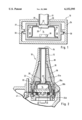
- FIG. 2 is a view of an embodiment of a probe tip of the present invention for a radiation thermometer.
- the probe tip 10 comprises a waveguide device 12 for transmitting the infrared radiation to be measured from an entrance opening (not shown) to a radiation sensor or a thermoelectric transducer 14 converting the partial temperature increase produced by the radiation in the sensor into an electrical output signal from which the target temperature is determined by means of a downstream electronic measurement circuitry (not shown).
- the radiation or temperature sensor 14 comprises a sensor housing 16 in which thermocouples, for example, are arranged as sensor elements 18 which, via leads (not shown) in the bottom of the sensor housing 16, are connected to the downstream electronic measurement circuitry.
- the side of the sensor housing 16 close to the incident radiation or the waveguide device 12 is provided with a sensor window 20 for admitting the infrared radiation to be measured.
- the end of the waveguide device 12 and the radiation sensor 14 are thermally separated from one another by an air gap 22.
- the radiation sensor 14 is surrounded by a thermal coupling arrangement 24, 28, 30.
- the thermal coupling arrangement comprises a heat accumulating or concentrating device 24 which is in direct thermal contact with the waveguide device 12 at the location assigned reference numeral 26.
- an air gap provides for thermal insulation of the heat accumulating device 24 from a probe tip housing (not shown) towards the outside in order to maintain the heat input at a minimum possible level.
- a heat dissipating or distributing device 28 Disposed between the radiation sensor 14 and the heat accumulating device 24 is a heat dissipating or distributing device 28 which surrounds the radiation sensor 14 and is thermally insulated from the waveguide device 12 by the air gap 22.
- the heat accumulating device 24 and the heat dissipating device 28 are thermally insulated from each other likewise by the air gap 22.
- the heat dissipating device 28 Towards the interior the heat dissipating device 28 is thermally insulated from the sides of the sensor housing 16 by an air gap 32, whilst being in direct thermal contact with the side of the sensor housing 16 close to the incident radiation or the waveguide device 12, that is, the upper side or the lid of the housing 16, and the opposite side thereof, that is, the underside or the bottom of the housing 16.
- the heat dissipating device 28 has substantially its entire surface area, except for the sensor window 20, in abutting engagement with the above-mentioned sides of the sensor housing 16.
- the heat accumulating device 24 and the heat dissipating device 28 are preferably made of a material conducting heat well, as for example, copper, aluminum, zinc or the like, in order to ensure optimum heat transference and rapid adjustment of the thermal equilibrium.
- thermal junction 30 On heating or cooling of the waveguide device 12 or the heat accumulating device 24 by external effect, temperature gradients occur in the components identified. Part of the thermal energy is initially transmitted from the heat accumulating device 24 through the thermal junction 30 to the heat dissipating device 28 which transfers it onwards to the bottom and the lid of the sensor housing 16.
- the location of the thermal junction 30 and the form of the heat dissipating device 28 are invariably selected such that heat transfer to the bottom and the lid of the sensor housing 16 takes place substantially uniformly so as to prevent where possible any temperature gradients in the radiation sensor 14 that would result in different levels of heating of the cold and hot junctions of the sensor 14 and in a sensor output signal reflecting this situation.
- the heat dissipating device 28 is configured and the thermal junction 30 is arranged so as to compensate not only for the customarily relatively large differences between the thermal capacities of bottom and lid, but also for the thermal coupling via the leads of the radiation sensor 14 into the bottom of the sensor housing 16, whereby an accurate temperature measurement is ensured also in cases where inhomogeneous heating occurs.
- the radiation sensor 14 is in thermal contact with the waveguide device 12 (and, where applicable, also with the window admitting radiation (not shown)) through the thermal coupling arrangement 24, 28, 30, it is not necessary to provide for compensation for the intrinsic emission of the waveguide device 12 (and the window admitting radiation). Nor is it necessary to compensate for null drifts due to temperature variations using a shutter, additional sensors, double radiation sensors or the like.
- the thermal coupling approach of the present invention also enables inexpensive thermopile or bolometer sensors to be utilized, thus eliminating the need for specifically optimized and expensive special types.
- FIG. 2 shows a particular embodiment of a probe tip of the present invention for a radiation thermometer.
- the probe tip 10 has at its forward end an entrance opening or window 34 for passage of the infrared radiation to be measured which is directed by a waveguide 12 to a radiation sensor 14 that is thermally insulated from the waveguide 12 by an air gap 22.
- the waveguide 12 is in thermal contact with a heat accumulating device 24 which, for simplified assembly, is comprised of an upper part 24a and a lower part 24 readily joinable together with the upper part 24a, the two parts being designed to have a relatively large thermal mass to reduce temperature gradients.
- a heat accumulating device 24 which, for simplified assembly, is comprised of an upper part 24a and a lower part 24 readily joinable together with the upper part 24a, the two parts being designed to have a relatively large thermal mass to reduce temperature gradients.
- an air gap 36 provides for thermal insulation towards the outside of the heat accumulating device 24 from a probe tip housing 38 typically made of plastic.
- the heat accumulating device 24 surrounds a heat dissipating device equally comprised of two parts 28a and 28b for ready joining together, from which it is thermally insulated by an air gap 22 except for some points of contact that may exist at the thermal junction. Between the lower part 24b of the heat accumulating device and the lower part 28b of the heat dissipating device, an elastic O-ring 31 is provided which has poor heat conductive properties and serves to compensate for tolerances or thermal expansion, if any.
- the upper part 28a of the heat dissipating device is thermally insulated from the sides of the sensor housing 16 by an air gap 32, and from the waveguide device 12 by the air gap 22, whilst being in direct thermal contact with the upper side or the lid of the sensor housing 16.
- the lower part 28b of the heat dissipating device has practically its entire surface area in thermal contact with the underside or the bottom of the sensor housing 16 in order to ensure an optimum possible heat transfer.
- the heat accumulating device 24 and the heat dissipating device 28 are made of ea material conducting heat well, as for example copper, aluminum, zinc or the like.
- the leads 40 of the sensor 14 are located within the heat accumulating device 24. Via a flexible printed circuit board 41, the sensor 14 is electrically connected to a downstream electronic circuitry (not shown) of the radiation thermometer for evaluation of the electrical output signals produced by the radiation sensor 14. To minimize the heat input via the leads 40, this printed circuit board is of a very thin configuration. For the same reason, it is also designed to be a poor heat conductor and is thermally coupled to the heat accumulating device 24 in close proximity to the O-ring 31.
- the thermal coupling of the sensor housing 16 to the waveguide device 12 or the surroundings as disclosed in the present invention enables a small, light-weight and compact probe tip to be created for easy-to-handle and user-friendly radiation thermometers in which erroneous readings attributable to temperature gradients are reliably avoided.
- the probe tip of the present invention has the added benefit of affording ease and economy of manufacture.
Landscapes
- Physics & Mathematics (AREA)
- General Physics & Mathematics (AREA)
- Spectroscopy & Molecular Physics (AREA)
- Measuring And Recording Apparatus For Diagnosis (AREA)
- Radiation Pyrometers (AREA)
Abstract
Description
Claims (15)
Applications Claiming Priority (3)
| Application Number | Priority Date | Filing Date | Title |
|---|---|---|---|
| DE19713608A DE19713608A1 (en) | 1997-04-02 | 1997-04-02 | Measuring tip for radiation thermometer |
| DE19713608 | 1997-04-02 | ||
| PCT/EP1998/001246 WO1998044322A1 (en) | 1997-04-02 | 1998-03-05 | Measuring tip for a radiation thermometer |
Publications (1)
| Publication Number | Publication Date |
|---|---|
| US6152595A true US6152595A (en) | 2000-11-28 |
Family
ID=7825239
Family Applications (1)
| Application Number | Title | Priority Date | Filing Date |
|---|---|---|---|
| US09/180,176 Expired - Lifetime US6152595A (en) | 1997-04-02 | 1998-03-05 | Measuring tip for a radiation thermometer |
Country Status (11)
| Country | Link |
|---|---|
| US (1) | US6152595A (en) |
| EP (1) | EP0972175B1 (en) |
| JP (1) | JP2001517120A (en) |
| KR (1) | KR100539205B1 (en) |
| CN (1) | CN1281181C (en) |
| AT (1) | ATE295532T1 (en) |
| AU (1) | AU6827398A (en) |
| DE (2) | DE19713608A1 (en) |
| HK (1) | HK1024296A1 (en) |
| TW (1) | TW417017B (en) |
| WO (1) | WO1998044322A1 (en) |
Cited By (16)
| Publication number | Priority date | Publication date | Assignee | Title |
|---|---|---|---|---|
| US6425688B1 (en) * | 2000-04-21 | 2002-07-30 | Actherm Inc. | Infrared temperature wave guide device |
| US20020131473A1 (en) * | 1997-07-16 | 2002-09-19 | Tomoyasu Konno | Ear type clinical thermometer |
| US6572264B1 (en) * | 1998-12-15 | 2003-06-03 | Citizen Watch Co., Ltd. | Radiation clinical thermometer |
| US6637931B2 (en) | 2001-07-19 | 2003-10-28 | Oriental System Technology Inc. | Probe for use in an infrared thermometer |
| US20040022297A1 (en) * | 2000-06-13 | 2004-02-05 | Makoto Tabata | Pyrometer |
| US20040057493A1 (en) * | 2002-07-15 | 2004-03-25 | Chuji Ishikawa | Temperature detecting unit and fixing apparatus |
| US6749334B2 (en) | 2002-08-09 | 2004-06-15 | Radiant Innovation Inc. | Ear thermometer probe structure |
| US6789936B1 (en) * | 1999-06-28 | 2004-09-14 | Braun Gmbh | Infrared thermometer for performing temperature measurements at different sites |
| WO2006002522A1 (en) * | 2004-06-30 | 2006-01-12 | Trojan Technologies Inc. | Radiation sensor device and fluid treatment system containing same |
| US20060098709A1 (en) * | 2004-11-09 | 2006-05-11 | Horng-Tsann Huang | Infrared thermometer |
| US20070127545A1 (en) * | 2005-12-01 | 2007-06-07 | Oriental System Technology Inc. | Probe assembly of infrared thermometer |
| US20080267254A1 (en) * | 2007-04-27 | 2008-10-30 | Actherm Inc. | Infrared thermometer |
| US20100265986A1 (en) * | 2009-04-20 | 2010-10-21 | Welch Allyn, Inc. | Calibrated assembly for ir thermometer apparatus |
| US20100284436A1 (en) * | 2009-05-05 | 2010-11-11 | Welch Allyn, Inc. | Ir thermometer thermal isolation tip assembly |
| JP5996139B1 (en) * | 2016-03-31 | 2016-09-21 | 興和株式会社 | Infrared thermometer |
| CN111795755A (en) * | 2019-04-03 | 2020-10-20 | 法雷奥开关和传感器有限责任公司 | Sensor device, method for producing a sensor device, and vehicle |
Families Citing this family (8)
| Publication number | Priority date | Publication date | Assignee | Title |
|---|---|---|---|---|
| JP2000254103A (en) * | 1999-03-11 | 2000-09-19 | Citizen Watch Co Ltd | Radiation thermometer |
| US7897920B2 (en) * | 2005-09-21 | 2011-03-01 | Analog Devices, Inc. | Radiation sensor device and method |
| DE102006021528B3 (en) | 2006-02-15 | 2007-09-13 | Epcos Ag | sensor |
| WO2012172501A1 (en) * | 2011-06-15 | 2012-12-20 | Koninklijke Philips Electronics N.V. | Peripheral temperature measuring |
| TWM480991U (en) * | 2013-12-05 | 2014-07-01 | Yofa Biotechnology Co Ltd | Patch-type temperature measuring apparatus |
| KR101804374B1 (en) | 2016-11-30 | 2017-12-04 | 주식회사 씨알아이지 | Infrared ear thermometer and method for measuring body temperature using the same |
| CN106710121A (en) * | 2017-02-28 | 2017-05-24 | 桂林电子科技大学 | Forest fire positioning device based on bionic inductor |
| KR102599974B1 (en) * | 2021-02-17 | 2023-11-07 | 부경대학교 산학협력단 | Measurement method of infrared thermometer with improved measurement reliability |
Citations (11)
| Publication number | Priority date | Publication date | Assignee | Title |
|---|---|---|---|---|
| US2416775A (en) * | 1942-04-20 | 1947-03-04 | O W Wortman | Cooled radiation thermocouple |
| US2811856A (en) * | 1946-03-29 | 1957-11-05 | Honeywell Regulator Co | Temperature measuring apparatus |
| JPS6391526A (en) * | 1986-10-06 | 1988-04-22 | Nireko:Kk | Radiation thermometer |
| WO1989004891A1 (en) * | 1987-11-24 | 1989-06-01 | Kober Ag | Device for bridging expansion joints |
| US4932789A (en) * | 1988-04-12 | 1990-06-12 | Citizen Watch Co., Ltd. | Radiation clinical thermometer |
| WO1994002467A1 (en) * | 1992-07-28 | 1994-02-03 | Instituto Luso Farmaco D'italia S.P.A. | Imidazole ethers having a ii antagonist activity |
| US5293877A (en) * | 1990-12-12 | 1994-03-15 | Sherwood Ims, Inc. | Body temperature thermometer and method fo measuring human body temperature utilizing calibration mapping |
| US5445158A (en) * | 1988-12-06 | 1995-08-29 | Exergen Corporation | Radiation detector probe |
| EP0763349A2 (en) * | 1988-12-06 | 1997-03-19 | Exergen Corporation | Radiation detector for tymphanic temperature measurement |
| US5653238A (en) * | 1988-12-06 | 1997-08-05 | Exergen Corporation | Radiation detector probe |
| US5857775A (en) * | 1995-09-05 | 1999-01-12 | Tyco Group S.A.R.L. | Thermometer probe having a watertight seal |
Family Cites Families (2)
| Publication number | Priority date | Publication date | Assignee | Title |
|---|---|---|---|---|
| US5018872A (en) * | 1988-11-01 | 1991-05-28 | Diatek, Inc. | Probe assembly for infrared thermometer |
| US5368038A (en) * | 1993-03-08 | 1994-11-29 | Thermoscan Inc. | Optical system for an infrared thermometer |
-
1997
- 1997-04-02 DE DE19713608A patent/DE19713608A1/en not_active Ceased
-
1998
- 1998-03-05 AT AT98913648T patent/ATE295532T1/en not_active IP Right Cessation
- 1998-03-05 KR KR10-1999-7008945A patent/KR100539205B1/en not_active IP Right Cessation
- 1998-03-05 EP EP98913648A patent/EP0972175B1/en not_active Expired - Lifetime
- 1998-03-05 DE DE59812790T patent/DE59812790D1/en not_active Expired - Lifetime
- 1998-03-05 WO PCT/EP1998/001246 patent/WO1998044322A1/en not_active Application Discontinuation
- 1998-03-05 JP JP54109398A patent/JP2001517120A/en active Pending
- 1998-03-05 AU AU68273/98A patent/AU6827398A/en not_active Abandoned
- 1998-03-05 CN CNB98803672XA patent/CN1281181C/en not_active Expired - Lifetime
- 1998-03-05 US US09/180,176 patent/US6152595A/en not_active Expired - Lifetime
- 1998-03-06 TW TW087103304A patent/TW417017B/en not_active IP Right Cessation
-
2000
- 2000-06-12 HK HK00103502A patent/HK1024296A1/en not_active IP Right Cessation
Patent Citations (12)
| Publication number | Priority date | Publication date | Assignee | Title |
|---|---|---|---|---|
| US2416775A (en) * | 1942-04-20 | 1947-03-04 | O W Wortman | Cooled radiation thermocouple |
| US2811856A (en) * | 1946-03-29 | 1957-11-05 | Honeywell Regulator Co | Temperature measuring apparatus |
| JPS6391526A (en) * | 1986-10-06 | 1988-04-22 | Nireko:Kk | Radiation thermometer |
| WO1989004891A1 (en) * | 1987-11-24 | 1989-06-01 | Kober Ag | Device for bridging expansion joints |
| US4932789A (en) * | 1988-04-12 | 1990-06-12 | Citizen Watch Co., Ltd. | Radiation clinical thermometer |
| EP0593415A2 (en) * | 1988-04-12 | 1994-04-20 | Citizen Watch Co., Ltd. | Radiation clinical thermometer |
| US5445158A (en) * | 1988-12-06 | 1995-08-29 | Exergen Corporation | Radiation detector probe |
| EP0763349A2 (en) * | 1988-12-06 | 1997-03-19 | Exergen Corporation | Radiation detector for tymphanic temperature measurement |
| US5653238A (en) * | 1988-12-06 | 1997-08-05 | Exergen Corporation | Radiation detector probe |
| US5293877A (en) * | 1990-12-12 | 1994-03-15 | Sherwood Ims, Inc. | Body temperature thermometer and method fo measuring human body temperature utilizing calibration mapping |
| WO1994002467A1 (en) * | 1992-07-28 | 1994-02-03 | Instituto Luso Farmaco D'italia S.P.A. | Imidazole ethers having a ii antagonist activity |
| US5857775A (en) * | 1995-09-05 | 1999-01-12 | Tyco Group S.A.R.L. | Thermometer probe having a watertight seal |
Cited By (31)
| Publication number | Priority date | Publication date | Assignee | Title |
|---|---|---|---|---|
| US20020131473A1 (en) * | 1997-07-16 | 2002-09-19 | Tomoyasu Konno | Ear type clinical thermometer |
| US6572264B1 (en) * | 1998-12-15 | 2003-06-03 | Citizen Watch Co., Ltd. | Radiation clinical thermometer |
| US6789936B1 (en) * | 1999-06-28 | 2004-09-14 | Braun Gmbh | Infrared thermometer for performing temperature measurements at different sites |
| US6425688B1 (en) * | 2000-04-21 | 2002-07-30 | Actherm Inc. | Infrared temperature wave guide device |
| US20040228386A1 (en) * | 2000-06-13 | 2004-11-18 | Omron Corporation | Radiation thermometer |
| US7036978B2 (en) | 2000-06-13 | 2006-05-02 | Omron Corporation | Pyrometer |
| US7380981B2 (en) | 2000-06-13 | 2008-06-03 | Omron Healthcare Co., Ltd. | Radiation thermometer |
| US20040022297A1 (en) * | 2000-06-13 | 2004-02-05 | Makoto Tabata | Pyrometer |
| US7434992B2 (en) * | 2000-06-13 | 2008-10-14 | Omron Healthcare Co., Ltd. | Radiation thermometer |
| US20040233968A1 (en) * | 2000-06-13 | 2004-11-25 | Omron Corporation | Radiation thermometer |
| US6637931B2 (en) | 2001-07-19 | 2003-10-28 | Oriental System Technology Inc. | Probe for use in an infrared thermometer |
| DE10147358B4 (en) * | 2001-07-19 | 2006-03-16 | Oriental System Technology Inc. | Probe for use in an infrared thermometer |
| US7040806B2 (en) * | 2002-07-15 | 2006-05-09 | Ricoh Company, Ltd. | Temperature detecting unit and fixing apparatus |
| US20040057493A1 (en) * | 2002-07-15 | 2004-03-25 | Chuji Ishikawa | Temperature detecting unit and fixing apparatus |
| US20060153275A1 (en) * | 2002-07-15 | 2006-07-13 | Chuji Ishikawa | Temperature detecting unit and fixing apparatus |
| US7363859B2 (en) | 2002-07-15 | 2008-04-29 | Ricoh Company, Ltd. | Temperature detecting unit with fixing apparatus |
| US6749334B2 (en) | 2002-08-09 | 2004-06-15 | Radiant Innovation Inc. | Ear thermometer probe structure |
| WO2006002522A1 (en) * | 2004-06-30 | 2006-01-12 | Trojan Technologies Inc. | Radiation sensor device and fluid treatment system containing same |
| US20060098709A1 (en) * | 2004-11-09 | 2006-05-11 | Horng-Tsann Huang | Infrared thermometer |
| US7275867B2 (en) * | 2005-12-01 | 2007-10-02 | Oriental System Technology Inc. | Probe assembly of infrared thermometer |
| US20070127545A1 (en) * | 2005-12-01 | 2007-06-07 | Oriental System Technology Inc. | Probe assembly of infrared thermometer |
| US20080267254A1 (en) * | 2007-04-27 | 2008-10-30 | Actherm Inc. | Infrared thermometer |
| US7665892B2 (en) | 2007-04-27 | 2010-02-23 | Actherm Inc. | Infrared thermometer |
| US20100265986A1 (en) * | 2009-04-20 | 2010-10-21 | Welch Allyn, Inc. | Calibrated assembly for ir thermometer apparatus |
| US8186876B2 (en) | 2009-04-20 | 2012-05-29 | Welch Allyn, Inc. | Calibrated assembly for IR thermometer apparatus |
| US20100284436A1 (en) * | 2009-05-05 | 2010-11-11 | Welch Allyn, Inc. | Ir thermometer thermal isolation tip assembly |
| US8136985B2 (en) | 2009-05-05 | 2012-03-20 | Welch Allyn, Inc. | IR thermometer thermal isolation tip assembly |
| JP5996139B1 (en) * | 2016-03-31 | 2016-09-21 | 興和株式会社 | Infrared thermometer |
| WO2017170837A1 (en) * | 2016-03-31 | 2017-10-05 | 興和株式会社 | Infrared thermometer |
| CN111795755A (en) * | 2019-04-03 | 2020-10-20 | 法雷奥开关和传感器有限责任公司 | Sensor device, method for producing a sensor device, and vehicle |
| CN111795755B (en) * | 2019-04-03 | 2024-02-02 | 法雷奥开关和传感器有限责任公司 | Sensor device, method for producing a sensor device, and vehicle |
Also Published As
| Publication number | Publication date |
|---|---|
| DE59812790D1 (en) | 2005-06-16 |
| CN1281181C (en) | 2006-10-25 |
| AU6827398A (en) | 1998-10-22 |
| EP0972175A1 (en) | 2000-01-19 |
| HK1024296A1 (en) | 2000-10-05 |
| TW417017B (en) | 2001-01-01 |
| KR20010005869A (en) | 2001-01-15 |
| KR100539205B1 (en) | 2005-12-28 |
| WO1998044322A1 (en) | 1998-10-08 |
| EP0972175B1 (en) | 2005-05-11 |
| ATE295532T1 (en) | 2005-05-15 |
| CN1251168A (en) | 2000-04-19 |
| JP2001517120A (en) | 2001-10-02 |
| DE19713608A1 (en) | 1998-10-08 |
Similar Documents
| Publication | Publication Date | Title |
|---|---|---|
| US6152595A (en) | Measuring tip for a radiation thermometer | |
| US6129673A (en) | Infrared thermometer | |
| US7410290B2 (en) | Ear-type clinical thermometer | |
| KR100628283B1 (en) | Infrared sensor stabilisable in temperature, and infrared thermometer with a sensor of this type | |
| US6203194B1 (en) | Thermopile sensor for radiation thermometer or motion detector | |
| US6694174B2 (en) | Infrared thermometer with heatable probe tip and protective cover | |
| WO2001096825A1 (en) | Pyrometer | |
| CN112013969A (en) | Non-contact temperature measuring device and temperature measuring method thereof | |
| US20040057494A1 (en) | Ear thermometer with improved temperature coefficient and method of calibration thereof | |
| JPH0666639A (en) | Infrared thermometer | |
| JP2003070750A (en) | Temperature compensator for ear thermometer | |
| CN209639834U (en) | A kind of infrared thermometer | |
| CN210487079U (en) | Infrared temperature sensor, probe comprising same and infrared thermometer | |
| JP2003156395A (en) | Infrared temperature sensor | |
| JP3099470B2 (en) | Non-contact temperature measurement system for centrifuge | |
| JP4490580B2 (en) | Infrared sensor | |
| CN112113664A (en) | Infrared temperature sensor, probe comprising same and infrared thermometer | |
| JPS6171326A (en) | Photodetector | |
| JP3176798B2 (en) | Radiant heat sensor | |
| JPH10290790A (en) | Radiation thermometer | |
| JPH08278203A (en) | Infrared ray radiation thermometer | |
| GB2107455A (en) | Apparatus for contactless measurement of temperature | |
| JP2005334254A (en) | Eardrum thermometer | |
| JP3175775B2 (en) | Temperature measurement method of radiation thermometer and radiation thermometer | |
| EP0999437A1 (en) | Apparatus for measuring internal body temperature utilizing infrared emissions |
Legal Events
| Date | Code | Title | Description |
|---|---|---|---|
| AS | Assignment |
Owner name: BRAUN AKTIENGESELLSCHAFT, GERMANY Free format text: ASSIGNMENT OF ASSIGNORS INTEREST;ASSIGNORS:BEERWERTH, FRANK;KRAUS, BERNHARD;HONNEFELLER, KATJA;REEL/FRAME:009751/0433 Effective date: 19980831 |
|
| AS | Assignment |
Owner name: BRAUN GMBH, GERMANY Free format text: CHANGE OF NAME;ASSIGNOR:BRAUN AKTIENGESELLSCHAFT;REEL/FRAME:010654/0006 Effective date: 19990901 |
|
| STCF | Information on status: patent grant |
Free format text: PATENTED CASE |
|
| FPAY | Fee payment |
Year of fee payment: 4 |
|
| AS | Assignment |
Owner name: KAZ USA, INC., MASSACHUSETTS Free format text: ASSIGNMENT OF ASSIGNORS INTEREST;ASSIGNOR:BRAUN GMBH;REEL/FRAME:019690/0236 Effective date: 20061208 |
|
| FPAY | Fee payment |
Year of fee payment: 8 |
|
| FPAY | Fee payment |
Year of fee payment: 12 |
|
| AS | Assignment |
Owner name: HELEN OF TROY LIMITED, BARBADOS Free format text: ASSIGNMENT OF ASSIGNORS INTEREST;ASSIGNOR:KAZ USA, INC.;REEL/FRAME:032264/0612 Effective date: 20131101 |