US6152559A - Ink-jet printing device having purging arrangement - Google Patents
Ink-jet printing device having purging arrangement Download PDFInfo
- Publication number
- US6152559A US6152559A US08/976,042 US97604297A US6152559A US 6152559 A US6152559 A US 6152559A US 97604297 A US97604297 A US 97604297A US 6152559 A US6152559 A US 6152559A
- Authority
- US
- United States
- Prior art keywords
- ink
- tank
- channel
- printing device
- jet printing
- Prior art date
- Legal status (The legal status is an assumption and is not a legal conclusion. Google has not performed a legal analysis and makes no representation as to the accuracy of the status listed.)
- Expired - Lifetime
Links
Images

Classifications
-
- B—PERFORMING OPERATIONS; TRANSPORTING
- B41—PRINTING; LINING MACHINES; TYPEWRITERS; STAMPS
- B41J—TYPEWRITERS; SELECTIVE PRINTING MECHANISMS, i.e. MECHANISMS PRINTING OTHERWISE THAN FROM A FORME; CORRECTION OF TYPOGRAPHICAL ERRORS
- B41J2/00—Typewriters or selective printing mechanisms characterised by the printing or marking process for which they are designed
- B41J2/005—Typewriters or selective printing mechanisms characterised by the printing or marking process for which they are designed characterised by bringing liquid or particles selectively into contact with a printing material
- B41J2/01—Ink jet
- B41J2/17—Ink jet characterised by ink handling
- B41J2/175—Ink supply systems ; Circuit parts therefor
- B41J2/17503—Ink cartridges
- B41J2/17556—Means for regulating the pressure in the cartridge
-
- B—PERFORMING OPERATIONS; TRANSPORTING
- B41—PRINTING; LINING MACHINES; TYPEWRITERS; STAMPS
- B41J—TYPEWRITERS; SELECTIVE PRINTING MECHANISMS, i.e. MECHANISMS PRINTING OTHERWISE THAN FROM A FORME; CORRECTION OF TYPOGRAPHICAL ERRORS
- B41J2/00—Typewriters or selective printing mechanisms characterised by the printing or marking process for which they are designed
- B41J2/005—Typewriters or selective printing mechanisms characterised by the printing or marking process for which they are designed characterised by bringing liquid or particles selectively into contact with a printing material
- B41J2/01—Ink jet
- B41J2/17—Ink jet characterised by ink handling
- B41J2/175—Ink supply systems ; Circuit parts therefor
-
- B—PERFORMING OPERATIONS; TRANSPORTING
- B41—PRINTING; LINING MACHINES; TYPEWRITERS; STAMPS
- B41J—TYPEWRITERS; SELECTIVE PRINTING MECHANISMS, i.e. MECHANISMS PRINTING OTHERWISE THAN FROM A FORME; CORRECTION OF TYPOGRAPHICAL ERRORS
- B41J2202/00—Embodiments of or processes related to ink-jet or thermal heads
- B41J2202/01—Embodiments of or processes related to ink-jet heads
- B41J2202/12—Embodiments of or processes related to ink-jet heads with ink circulating through the whole print head
Definitions
- the present invention relates to an ink-jet printing device having a ink-jet head purging arrangement.
- Control of ink drops in an ink-jet printing device is essential in order to produce high quality printed documents.
- an object of the present invention to provide an ink-jet printing device capable of minimizing the amount of ink that is expelled when purging the ink head and ink supply device, while reliably eliminating the air bubbles and solid matter, thereby guaranteeing lasting and stable printing quality.
- an ink-jet printing device including an ink-jet head, first and second ink channels, an ink tank, and a pressure applying device.
- the ink-jet head has a plurality of parallel pressure chambers each having one end and another end and arrayed side by side in an array direction.
- the head also forms nozzles connected to the one end of the pressure chambers and a manifold connected to the other end of the pressure chambers.
- the plurality of pressure chambers and nozzles provide a first flow resistance to ink flow.
- the manifold extends in the array direction and has an inlet end positioned adjacent a first pressure chamber and an outlet end positioned adjacent a last pressure chamber.
- the first ink channel has one end connected to the inlet end of the manifold.
- the first ink channel has another end.
- the second ink channel has one end connected to the outlet end of the manifold and has another end.
- the second ink channel provides a second flow resistance to ink flow.
- the first flow resistance is 1 to 5 times the second flow resistance.
- the ink tank accumulates therein an ink.
- the another end of the first ink channel and the another end of the second ink channel are connected to the ink tank for supplying the ink from the ink tank to the ink-jet head through the first ink channel and for circulating the ink in the ink-jet head to the ink tank through the second ink channel.
- the pressure applying device is adapted for applying pressure to ink accumulated in the ink tank for supplying the ink in the ink tank toward the first ink channel.
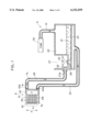
- FIG. 1 is a cross-sectional view showing relevant parts of an ink supply system and an ink jet head of an ink-jet printing device according to one embodiment of the present invention.
- FIG. 2 is a perspective view showing a printing mechanism of the ink-jet printing device according to the embodiment.
- the ink-jet printing device includes a pair of side frames 1, a shaft 2 rotatably supported between the pair of side frames 1, a platen 3 coaxially mounted over the shaft 2, and a motor 4 for rotationally driving the platen 3 by way of a gear transmissions 12.
- the device further includes a pair of guide rods 8 extending between the side frames 1 and in parallel to the platen 3, a carriage 7 supported on the two guide rods 8 and slidingly movable therealong, an ink supply device 5 and an ink-jet head 6 mounted on the carriage 7 and in confrontation with the platen 3.
- the ink-jet printing device is further provided with a pair of pulleys 9, a timing belt 10 looped around the pulleys 9 and engaged with the carriage 7, and a motor 11 for driving one of the pulleys 9 (the right pulley in FIG. 2).
- This pulley 9 is coaxially coupled on a drive shaft of the motor 11 and is driven in a rotating direction by the motor 11, causing the timing belt 10 to convey the carriage 7 back and forth along the platen 3.
- the ink-jet head 6 has a manifold 40, a plurality of pressure chambers 41 and a plurality of nozzles 42.
- An actuator (not shown) is provided in each of the pressure chambers 41.
- Each rear end of the pressure chamber 41 is in fluid communication with the manifold 40, and each front end of the pressure chamber 41 is connected to the nozzle 42 through which ink is ejected.
- the plurality of pressure chambers 41 are arrayed side by side in an array direction A shown in FIG. 2.
- the manifold 40 extends in the array direction A.
- the manifold has an inlet end 40a positioned adjacent a first pressure chamber 41F and an outlet end 40b positioned adjacent a last pressure chamber 41L.
- the ink supply device 5 includes an ink tank having a main tank 22 containing therein an ink 21.
- a filter 23 is provided in the lower portion of the main tank 22.
- the ink tank includes a sub tank 27 provided adjacent the main tank 22 and at the position above the filter 23.
- a first ink channel 24 is connected between a bottom portion of the main tank 22 and the ink inlet 40a of the manifold 40 for supplying ink 21 in the main tank 22 into the ink jet head 6.
- a second ink channel 26 is connected between the ink outlet 40b and the sub tank 27 for circulating the ink in the ink jet head 6 into the sub tank 27.
- a hole 27a is formed in the sub tank 27 for connecting one end of the second ink channel 26 to the sub tank 27, and a first cap 29 is provided for selectively capping the hole 27a. Further, a hole 28 is formed at a bottom wall of the sub tank 27 for providing fluid communication between the sub tank 27 and the main tank 21, and a second cap 30 is provided for selectively capping the hole 28.
- An air pressure pump or pneumatic pump 32 is connected to the main tank 22 via a pressure tube 31 for compressing the internal space of the main tank 22.
- the first cap 29 is closed and the second cap 30 is open. Ink drops are ejected from the nozzles 42 when the actuators (not shown) within the pressure chambers 41 are driven according to a printing pattern. At this time, ink that has passed from the main tank 22 through the filter 23 is supplied to the manifold 40 via the first ink channel 24. During the printing operation, ink 21 can be prevented from flowing in the reverse direction from the sub tank 27 through the second ink channel 26 by closing the first cap 29. Further, by opening the cap 30, the ink circulated into the sub tank 27 can flow into the main tank 22 through the hole 28. Since the filter 23 is positioned below the sub-tank 27, unwanted foreign particles or solidified ink can be trapped at the filter 21.
- the first cap 29 is opened and the second cap 30 is closed.
- Air pressure from the air pressure pump 32 is introduced into the main tank 22. Since the main tank 22 is hermetically sealed by the closure of the second cap 30, pressure within the main tank 22 increases, forcing ink from the main tank 22 to flow via the filter 23 and first ink channel 24 to the manifold 40.
- the manifold 40 a portion of the ink is expelled from the nozzles 42 via the pressure chambers 41, while the remaining portion of ink is forced to flow into the sub tank 27 via the second ink channel 26.
- P pressure loss in kgf/cm 2
- r is the channel radius in cm
- L is the channel length in cm
- ⁇ is the viscosity of the fluid in kgfs/cm 2
- Q is the quantity of flow in cc/s.
- the flow resistance R can be represented by the ratio of the pressure loss P to the quantity of flow Q.
- a total flow resistance of the ink head 6 can be represented by R B /N, wherein N is the number of pressure chambers 41 connecting to the manifold 40. Further, it is assumed that Q 1 is the quantity of ink expelled from the nozzles 42 during purging operation, and Q 2 is the quantity of ink recovered into the sub tank 27 during the purging operation.
- the resistance in the plurality of parallel channels connecting the pressure chambers 41 and nozzles 42 is set to between about 1 and 5 times the resistance in the second ink channel 26, so that the following equation is satisfied.
- this ratio is less than 1, the amount of ink expelled from the nozzles 42 will increase, which is wasteful. Further, air in the second ink channel 26 cannot be adequately purged or discharged. On the other hand, if this ratio is greater than 5, the air in the pressure chambers 41 cannot be adequately discharged therefrom.
- Q 2 /Q 1 is preferably in a range of from 1.1 to 3.3, and more preferably, from 1.3 to 3.3. It should be noted that Q 2 /Q 1 is equivalent to R B /(R A ⁇ N).
- ink is expelled by increasing pressure in the main tank 22 so that the ink 21 flows through the manifold 40, the pressure chambers 41, and the nozzles 42, in that order.
- ink flows through the first ink channel 24, the manifold 40, and the second ink channel 26 to be collected in the sub tank 27.
- the amount of ink expelled and the amount of ink collected can be maintained at appropriate values since the resistance to ink in the plurality of parallel ink channels connecting the pressure chambers 41 and nozzles 42 is set from about 1 to 5 times the resistance of the second ink channel 26.
- the amount of ink that is expelled during the purging can be minimized, while reliably eliminating the air bubbles and solid matter.
- purging can be performed by a simple arrangement.
Abstract
Description
Q.sub.1 :Q.sub.2 =R.sub.A :R.sub.B /N
1≦R.sub.B /(R.sub.A ·N)≦5
              TABLE 1
______________________________________
Flow resistance
            Quantity of flow        Number of
(kgf · s/cm.sup.5)
            (cc/s)            ratio unsteady
R.sub.A
       R.sub.B  Q.sub.2 Q.sub.1 Q.sub.2 /Q.sub.1
                                      channels
______________________________________
0.702   97.4    0.073   0.0683  1.1   1˜5
0.702  116.7    0.075   0.0583  1.3   0˜3
0.267   97.4    0.157   0.0564  2.8   0˜3
0.267  116.7    0.159   0.0479  3.3   0˜5
0.113   97.4    0.262   0.0413  6.3   5˜9
0.113  116.7    0.266   0.0349  7.6    3˜12
______________________________________
Claims (11)
Applications Claiming Priority (2)
| Application Number | Priority Date | Filing Date | Title |
|---|---|---|---|
| JP8-310763 | 1996-11-21 | ||
| JP8310763A JPH10151761A (en) | 1996-11-21 | 1996-11-21 | Ink jet recorder |
Publications (1)
| Publication Number | Publication Date |
|---|---|
| US6152559A true US6152559A (en) | 2000-11-28 |
Family
ID=18009187
Family Applications (1)
| Application Number | Title | Priority Date | Filing Date |
|---|---|---|---|
| US08/976,042 Expired - Lifetime US6152559A (en) | 1996-11-21 | 1997-11-21 | Ink-jet printing device having purging arrangement |
Country Status (2)
| Country | Link |
|---|---|
| US (1) | US6152559A (en) |
| JP (1) | JPH10151761A (en) |
Cited By (45)
| Publication number | Priority date | Publication date | Assignee | Title |
|---|---|---|---|---|
| US6406137B1 (en) * | 1998-12-22 | 2002-06-18 | Canon Kabushiki Kaisha | Ink-jet print head and production method of ink-jet print head |
| EP1245392A1 (en) * | 2001-03-26 | 2002-10-02 | Fuji Xerox Co., Ltd. | Ink jet recording device and a method for designing the same |
| US6561637B2 (en) * | 2001-07-06 | 2003-05-13 | Brother Kogyo Kabushiki Kaisha | Ink jet head having buffer tank in fluid communication with ink circulation pathway |
| US6568799B1 (en) * | 2002-01-23 | 2003-05-27 | Eastman Kodak Company | Drop-on-demand ink jet printer with controlled fluid flow to effect drop ejection |
| EP1356946A1 (en) * | 2002-04-26 | 2003-10-29 | Hewlett-Packard Company | Re-circulating fluid delivery system |
| US6652080B2 (en) * | 2002-04-30 | 2003-11-25 | Hewlett-Packard Development Company, Lp. | Re-circulating fluid delivery system |
| US6663220B2 (en) * | 2000-08-28 | 2003-12-16 | Toshiba Tec Kabushiki Kaisha | Ink jet printer |
| US6685299B2 (en) | 2001-05-31 | 2004-02-03 | Brother Kogyo Kabushiki Kaisha | Ink jet head |
| US20040104984A1 (en) * | 1995-04-27 | 2004-06-03 | Hall Ronald W. | Method and apparatus for providing ink to an ink jet printing system |
| EP1359027A3 (en) * | 2002-04-30 | 2004-10-20 | Hewlett-Packard Company | Fluid delivery techniques with improved reliability |
| US20050007429A1 (en) * | 2003-07-08 | 2005-01-13 | Toshiba Tec Kabushiki Kaisha | Ink jet recording apparatus and ink jet head |
| WO2005007415A2 (en) | 2003-07-16 | 2005-01-27 | Xaar Technology Limited | Droplet deposition apparatus |
| US20050104943A1 (en) * | 2003-11-18 | 2005-05-19 | Toshiba Tec Kabushiki Kaisha | Ink jet apparatus |
| US20050146582A1 (en) * | 2004-01-07 | 2005-07-07 | Xerox Corporation | Print head reservoir having purge vents |
| US20050243145A1 (en) * | 2004-04-30 | 2005-11-03 | Essen Kevin C V | Elongated filter assembly |
| US20050243146A1 (en) * | 2004-04-30 | 2005-11-03 | Kevin Von Essen | Recirculation assembly |
| US20050270329A1 (en) * | 2004-04-30 | 2005-12-08 | Hoisington Paul A | Droplet ejection apparatus alignment |
| US20060044365A1 (en) * | 2004-08-30 | 2006-03-02 | Xerox Corporation | Ink jet apparatus |
| US20060055731A1 (en) * | 2004-09-13 | 2006-03-16 | Canon Kabushiki Kaisha | Ink jet head, ink jet printer and method for manufacturing ink jet head |
| US20060164475A1 (en) * | 2005-01-26 | 2006-07-27 | Takaichiro Umeda | Liquid Droplet Ejecting Apparatus |
| US20090109267A1 (en) * | 2007-10-29 | 2009-04-30 | Samsung Electronics Co., Ltd | Ink-jet image forming apparatus and method of controlling ink flow |
| US20100079559A1 (en) * | 2008-09-29 | 2010-04-01 | Greg Justice | Fluid Circulation System |
| US20110001780A1 (en) * | 2009-07-02 | 2011-01-06 | Fujifilm Dimatix, Inc. | Positioning jetting assemblies |
| USD652446S1 (en) | 2009-07-02 | 2012-01-17 | Fujifilm Dimatix, Inc. | Printhead assembly |
| USD653284S1 (en) | 2009-07-02 | 2012-01-31 | Fujifilm Dimatix, Inc. | Printhead frame |
| WO2012057758A1 (en) * | 2010-10-28 | 2012-05-03 | Hewlett-Packard Development Company L.P. | Fluid ejection assembly with circulation pump |
| WO2012058019A1 (en) * | 2010-10-26 | 2012-05-03 | Eastman Kodak Company | Liquid dispenser including filter in return port |
| CN101659147B (en) * | 2008-08-28 | 2012-05-09 | 兄弟工业株式会社 | Ink-jet recording apparatus |
| US20120113197A1 (en) * | 2010-11-09 | 2012-05-10 | Canon Kabushiki Kaisha | Recording apparatus and liquid ejection head |
| US8469494B2 (en) | 2009-06-30 | 2013-06-25 | Eastman Kodak Company | Flow through drop dispenser including porous member |
| US20140104348A1 (en) * | 2012-10-12 | 2014-04-17 | Seiko Epson Corporation | Liquid Ejecting Apparatus |
| US8721061B2 (en) | 2010-05-21 | 2014-05-13 | Hewlett-Packard Development Company, L.P. | Fluid ejection device with circulation pump |
| US8740453B2 (en) | 2010-05-21 | 2014-06-03 | Hewlett-Packard Development Company, L.P. | Microcalorimeter systems |
| US8757783B2 (en) | 2010-07-28 | 2014-06-24 | Hewlett-Packard Development Company, L.P. | Fluid ejection assembly with circulation pump |
| US9248659B2 (en) * | 2013-12-26 | 2016-02-02 | Seiko Epson Corporation | Filter unit, liquid ejecting head, and liquid ejecting apparatus |
| US9381739B2 (en) | 2013-02-28 | 2016-07-05 | Hewlett-Packard Development Company, L.P. | Fluid ejection assembly with circulation pump |
| US9395050B2 (en) | 2010-05-21 | 2016-07-19 | Hewlett-Packard Development Company, L.P. | Microfluidic systems and networks |
| WO2017188962A1 (en) * | 2016-04-28 | 2017-11-02 | Hewlett-Packard Development Company, L.P. | Microfluidic filtering |
| US9963739B2 (en) | 2010-05-21 | 2018-05-08 | Hewlett-Packard Development Company, L.P. | Polymerase chain reaction systems |
| US10132303B2 (en) | 2010-05-21 | 2018-11-20 | Hewlett-Packard Development Company, L.P. | Generating fluid flow in a fluidic network |
| US10173435B2 (en) | 2010-05-21 | 2019-01-08 | Hewlett-Packard Development Company, L.P. | Fluid ejection device including recirculation system |
| US20190255856A1 (en) * | 2018-02-19 | 2019-08-22 | Jun Ichinowatari | Liquid discharge device and liquid discharge apparatus |
| WO2019177582A1 (en) * | 2018-03-12 | 2019-09-19 | Hewlett-Packard Development Company, L.P. | Purging manifolds |
| US20200101740A1 (en) * | 2018-09-28 | 2020-04-02 | Seiko Epson Corporation | Liquid ejecting apparatus, and method of controlling liquid ejecting apparatus |
| US20220250388A1 (en) * | 2016-01-08 | 2022-08-11 | Canon Kabushiki Kaisha | Liquid ejection head, liquid ejection apparatus, and method of supplying liquid |
Families Citing this family (6)
| Publication number | Priority date | Publication date | Assignee | Title |
|---|---|---|---|---|
| US6257714B1 (en) * | 1995-10-27 | 2001-07-10 | Hewlett-Packard Company | Method and apparatus for removing air from an inkjet print cartridge |
| US6487774B1 (en) | 1998-01-22 | 2002-12-03 | Matsushita Electric Industrial Co., Ltd. | Method of forming an electronic component using ink |
| JP5440361B2 (en) * | 2010-04-27 | 2014-03-12 | 株式会社リコー | Liquid storage tank, liquid discharge head unit, and image forming apparatus |
| JP2013151100A (en) * | 2012-01-25 | 2013-08-08 | Seiko Epson Corp | Liquid supply system and liquid jet device |
| CN106553448B (en) * | 2015-09-29 | 2018-07-06 | 株式会社东芝 | Ink jet unit |
| JP6929616B2 (en) * | 2016-04-08 | 2021-09-01 | キヤノン株式会社 | Liquid discharge device |
Citations (4)
| Publication number | Priority date | Publication date | Assignee | Title |
|---|---|---|---|---|
| US4121222A (en) * | 1977-09-06 | 1978-10-17 | A. B. Dick Company | Drop counter ink replenishing system |
| US4380770A (en) * | 1979-11-22 | 1983-04-19 | Epson Corporation | Ink jet printer |
| US4558326A (en) * | 1982-09-07 | 1985-12-10 | Konishiroku Photo Industry Co., Ltd. | Purging system for ink jet recording apparatus |
| US5818485A (en) * | 1996-11-22 | 1998-10-06 | Xerox Corporation | Thermal ink jet printing system with continuous ink circulation through a printhead |
-
1996
- 1996-11-21 JP JP8310763A patent/JPH10151761A/en active Pending
-
1997
- 1997-11-21 US US08/976,042 patent/US6152559A/en not_active Expired - Lifetime
Patent Citations (4)
| Publication number | Priority date | Publication date | Assignee | Title |
|---|---|---|---|---|
| US4121222A (en) * | 1977-09-06 | 1978-10-17 | A. B. Dick Company | Drop counter ink replenishing system |
| US4380770A (en) * | 1979-11-22 | 1983-04-19 | Epson Corporation | Ink jet printer |
| US4558326A (en) * | 1982-09-07 | 1985-12-10 | Konishiroku Photo Industry Co., Ltd. | Purging system for ink jet recording apparatus |
| US5818485A (en) * | 1996-11-22 | 1998-10-06 | Xerox Corporation | Thermal ink jet printing system with continuous ink circulation through a printhead |
Cited By (85)
| Publication number | Priority date | Publication date | Assignee | Title |
|---|---|---|---|---|
| US20040104984A1 (en) * | 1995-04-27 | 2004-06-03 | Hall Ronald W. | Method and apparatus for providing ink to an ink jet printing system |
| US7114801B2 (en) * | 1995-04-27 | 2006-10-03 | Hewlett-Packard Development Company, L.P. | Method and apparatus for providing ink to an ink jet printing system |
| US6406137B1 (en) * | 1998-12-22 | 2002-06-18 | Canon Kabushiki Kaisha | Ink-jet print head and production method of ink-jet print head |
| US6663220B2 (en) * | 2000-08-28 | 2003-12-16 | Toshiba Tec Kabushiki Kaisha | Ink jet printer |
| EP1245392A1 (en) * | 2001-03-26 | 2002-10-02 | Fuji Xerox Co., Ltd. | Ink jet recording device and a method for designing the same |
| US6685299B2 (en) | 2001-05-31 | 2004-02-03 | Brother Kogyo Kabushiki Kaisha | Ink jet head |
| US6561637B2 (en) * | 2001-07-06 | 2003-05-13 | Brother Kogyo Kabushiki Kaisha | Ink jet head having buffer tank in fluid communication with ink circulation pathway |
| US6568799B1 (en) * | 2002-01-23 | 2003-05-27 | Eastman Kodak Company | Drop-on-demand ink jet printer with controlled fluid flow to effect drop ejection |
| US20050264626A1 (en) * | 2002-04-26 | 2005-12-01 | Childs Ashley E | Re-circulating fluid delivery systems |
| US6955425B2 (en) | 2002-04-26 | 2005-10-18 | Hewlett-Packard Development Company, L.P. | Re-circulating fluid delivery systems |
| EP1356946A1 (en) * | 2002-04-26 | 2003-10-29 | Hewlett-Packard Company | Re-circulating fluid delivery system |
| US7497562B2 (en) | 2002-04-26 | 2009-03-03 | Hewlett-Packard Development Company, L.P. | Re-circulating fluid delivery systems |
| EP1623836A2 (en) * | 2002-04-30 | 2006-02-08 | Hewlett-Packard Company, A Delaware Corporation | Fluid delivery techniques with improved reliability |
| EP1623836A3 (en) * | 2002-04-30 | 2008-08-06 | Hewlett-Packard Company, A Delaware Corporation | Fluid delivery techniques with improved reliability |
| EP1359027A3 (en) * | 2002-04-30 | 2004-10-20 | Hewlett-Packard Company | Fluid delivery techniques with improved reliability |
| US6652080B2 (en) * | 2002-04-30 | 2003-11-25 | Hewlett-Packard Development Company, Lp. | Re-circulating fluid delivery system |
| US20050007429A1 (en) * | 2003-07-08 | 2005-01-13 | Toshiba Tec Kabushiki Kaisha | Ink jet recording apparatus and ink jet head |
| US7341337B2 (en) * | 2003-07-08 | 2008-03-11 | Toshiba Tec Kabushiki Kaisha | Ink jet recording apparatus and ink jet head |
| US7806515B2 (en) | 2003-07-16 | 2010-10-05 | Xaar Technology Limited | Droplet deposition apparatus |
| WO2005007415A2 (en) | 2003-07-16 | 2005-01-27 | Xaar Technology Limited | Droplet deposition apparatus |
| WO2005007415A3 (en) * | 2003-07-16 | 2005-04-14 | Xaar Technology Ltd | Droplet deposition apparatus |
| US20070188564A1 (en) * | 2003-07-16 | 2007-08-16 | Xaar Technology Limited | Droplet deposition apparatus |
| US20050104943A1 (en) * | 2003-11-18 | 2005-05-19 | Toshiba Tec Kabushiki Kaisha | Ink jet apparatus |
| US7198361B2 (en) * | 2003-11-18 | 2007-04-03 | Toshiba Tec Kabushiki Kaisha | Ink jet apparatus |
| US7121658B2 (en) * | 2004-01-07 | 2006-10-17 | Xerox Corporation | Print head reservoir having purge vents |
| US20050146582A1 (en) * | 2004-01-07 | 2005-07-07 | Xerox Corporation | Print head reservoir having purge vents |
| US7673969B2 (en) | 2004-04-30 | 2010-03-09 | Fujifilm Dimatix, Inc. | Droplet ejection apparatus alignment |
| US7665815B2 (en) | 2004-04-30 | 2010-02-23 | Fujifilm Dimatix, Inc. | Droplet ejection apparatus alignment |
| US8231202B2 (en) | 2004-04-30 | 2012-07-31 | Fujifilm Dimatix, Inc. | Droplet ejection apparatus alignment |
| US20050280678A1 (en) * | 2004-04-30 | 2005-12-22 | Andreas Bibl | Droplet ejection apparatus alignment |
| US20050243145A1 (en) * | 2004-04-30 | 2005-11-03 | Essen Kevin C V | Elongated filter assembly |
| US7413284B2 (en) | 2004-04-30 | 2008-08-19 | Fujifilm Dimatix, Inc. | Mounting assembly |
| US7413300B2 (en) * | 2004-04-30 | 2008-08-19 | Fujifilm Dimatix, Inc. | Recirculation assembly |
| US20080211872A1 (en) * | 2004-04-30 | 2008-09-04 | Fujifilm Dimatix, Inc. | Droplet ejection apparatus alignment |
| US20050243146A1 (en) * | 2004-04-30 | 2005-11-03 | Kevin Von Essen | Recirculation assembly |
| US7448741B2 (en) | 2004-04-30 | 2008-11-11 | Fujifilm Dimatix, Inc. | Elongated filter assembly |
| US20050270329A1 (en) * | 2004-04-30 | 2005-12-08 | Hoisington Paul A | Droplet ejection apparatus alignment |
| US20060044365A1 (en) * | 2004-08-30 | 2006-03-02 | Xerox Corporation | Ink jet apparatus |
| US7380920B2 (en) * | 2004-08-30 | 2008-06-03 | Xerox Corporation | Ink jet apparatus |
| US7410241B2 (en) * | 2004-09-13 | 2008-08-12 | Canon Kabushiki Kaisha | Ink jet head, ink jet printer and method for manufacturing ink jet head |
| US20060055731A1 (en) * | 2004-09-13 | 2006-03-16 | Canon Kabushiki Kaisha | Ink jet head, ink jet printer and method for manufacturing ink jet head |
| US7422313B2 (en) | 2005-01-26 | 2008-09-09 | Brother Kogyo Kabushiki Kaisha | Liquid droplet ejecting apparatus |
| US20060164475A1 (en) * | 2005-01-26 | 2006-07-27 | Takaichiro Umeda | Liquid Droplet Ejecting Apparatus |
| US20090109267A1 (en) * | 2007-10-29 | 2009-04-30 | Samsung Electronics Co., Ltd | Ink-jet image forming apparatus and method of controlling ink flow |
| US8342666B2 (en) * | 2007-10-29 | 2013-01-01 | Samsung Electronics Co., Ltd. | Ink-jet image forming apparatus and method of controlling ink flow |
| CN101659147B (en) * | 2008-08-28 | 2012-05-09 | 兄弟工业株式会社 | Ink-jet recording apparatus |
| US20100079559A1 (en) * | 2008-09-29 | 2010-04-01 | Greg Justice | Fluid Circulation System |
| US8469494B2 (en) | 2009-06-30 | 2013-06-25 | Eastman Kodak Company | Flow through drop dispenser including porous member |
| US8517508B2 (en) | 2009-07-02 | 2013-08-27 | Fujifilm Dimatix, Inc. | Positioning jetting assemblies |
| US20110001780A1 (en) * | 2009-07-02 | 2011-01-06 | Fujifilm Dimatix, Inc. | Positioning jetting assemblies |
| USD652446S1 (en) | 2009-07-02 | 2012-01-17 | Fujifilm Dimatix, Inc. | Printhead assembly |
| USD653284S1 (en) | 2009-07-02 | 2012-01-31 | Fujifilm Dimatix, Inc. | Printhead frame |
| US10132303B2 (en) | 2010-05-21 | 2018-11-20 | Hewlett-Packard Development Company, L.P. | Generating fluid flow in a fluidic network |
| US9963739B2 (en) | 2010-05-21 | 2018-05-08 | Hewlett-Packard Development Company, L.P. | Polymerase chain reaction systems |
| US10173435B2 (en) | 2010-05-21 | 2019-01-08 | Hewlett-Packard Development Company, L.P. | Fluid ejection device including recirculation system |
| US11260668B2 (en) | 2010-05-21 | 2022-03-01 | Hewlett-Packard Development Company, L.P. | Fluid ejection device including recirculation system |
| US10415086B2 (en) | 2010-05-21 | 2019-09-17 | Hewlett-Packard Development Company, L.P. | Polymerase chain reaction systems |
| US9395050B2 (en) | 2010-05-21 | 2016-07-19 | Hewlett-Packard Development Company, L.P. | Microfluidic systems and networks |
| US8721061B2 (en) | 2010-05-21 | 2014-05-13 | Hewlett-Packard Development Company, L.P. | Fluid ejection device with circulation pump |
| US8740453B2 (en) | 2010-05-21 | 2014-06-03 | Hewlett-Packard Development Company, L.P. | Microcalorimeter systems |
| US10272691B2 (en) | 2010-05-21 | 2019-04-30 | Hewlett-Packard Development Company, L.P. | Microfluidic systems and networks |
| US8757783B2 (en) | 2010-07-28 | 2014-06-24 | Hewlett-Packard Development Company, L.P. | Fluid ejection assembly with circulation pump |
| WO2012058019A1 (en) * | 2010-10-26 | 2012-05-03 | Eastman Kodak Company | Liquid dispenser including filter in return port |
| US8939531B2 (en) | 2010-10-28 | 2015-01-27 | Hewlett-Packard Development Company, L.P. | Fluid ejection assembly with circulation pump |
| CN103153627B (en) * | 2010-10-28 | 2016-02-24 | 惠普发展公司,有限责任合伙企业 | There is the fluid ejection assembly of circulating pump |
| CN103153627A (en) * | 2010-10-28 | 2013-06-12 | 惠普发展公司,有限责任合伙企业 | Fluid ejection assembly with circulation pump |
| WO2012057758A1 (en) * | 2010-10-28 | 2012-05-03 | Hewlett-Packard Development Company L.P. | Fluid ejection assembly with circulation pump |
| US9108425B2 (en) | 2010-11-09 | 2015-08-18 | Canon Kabushiki Kaisha | Recording apparatus and liquid ejection head |
| US8794746B2 (en) | 2010-11-09 | 2014-08-05 | Canon Kabushiki Kaisha | Recording apparatus and liquid ejection head |
| US8517518B2 (en) * | 2010-11-09 | 2013-08-27 | Canon Kabushiki Kaisha | Recording apparatus and liquid ejection head |
| US20120113197A1 (en) * | 2010-11-09 | 2012-05-10 | Canon Kabushiki Kaisha | Recording apparatus and liquid ejection head |
| US9044957B2 (en) * | 2012-10-12 | 2015-06-02 | Seiko Epson Corporation | Liquid ejecting apparatus |
| US20140104348A1 (en) * | 2012-10-12 | 2014-04-17 | Seiko Epson Corporation | Liquid Ejecting Apparatus |
| US9381739B2 (en) | 2013-02-28 | 2016-07-05 | Hewlett-Packard Development Company, L.P. | Fluid ejection assembly with circulation pump |
| US9248659B2 (en) * | 2013-12-26 | 2016-02-02 | Seiko Epson Corporation | Filter unit, liquid ejecting head, and liquid ejecting apparatus |
| US20220250388A1 (en) * | 2016-01-08 | 2022-08-11 | Canon Kabushiki Kaisha | Liquid ejection head, liquid ejection apparatus, and method of supplying liquid |
| WO2017188962A1 (en) * | 2016-04-28 | 2017-11-02 | Hewlett-Packard Development Company, L.P. | Microfluidic filtering |
| US10646868B2 (en) | 2016-04-28 | 2020-05-12 | Hewlett-Packard Development Company, L.P. | Microfluidic filtering |
| US20190255856A1 (en) * | 2018-02-19 | 2019-08-22 | Jun Ichinowatari | Liquid discharge device and liquid discharge apparatus |
| US10618304B2 (en) * | 2018-02-19 | 2020-04-14 | Ricoh Company, Ltd. | Liquid discharge device and liquid discharge apparatus |
| WO2019177582A1 (en) * | 2018-03-12 | 2019-09-19 | Hewlett-Packard Development Company, L.P. | Purging manifolds |
| US11273646B2 (en) | 2018-03-12 | 2022-03-15 | Hewlett-Packard Development Company, L.P. | Fluid delivery |
| US11597206B2 (en) | 2018-03-12 | 2023-03-07 | Hewlett-Packard Development Company, L.P. | Purging manifolds |
| US20200101740A1 (en) * | 2018-09-28 | 2020-04-02 | Seiko Epson Corporation | Liquid ejecting apparatus, and method of controlling liquid ejecting apparatus |
| US10906314B2 (en) * | 2018-09-28 | 2021-02-02 | Seiko Epson Corporation | Liquid ejecting apparatus, and method of controlling liquid ejecting apparatus |
Also Published As
| Publication number | Publication date |
|---|---|
| JPH10151761A (en) | 1998-06-09 |
Similar Documents
| Publication | Publication Date | Title |
|---|---|---|
| US6152559A (en) | Ink-jet printing device having purging arrangement | |
| DE602006000425T2 (en) | Liquid ejection device and liquid filling method of a liquid ejection device | |
| CA2049787C (en) | Ink jet printing apparatus | |
| KR101430934B1 (en) | Ink-jet image forming apparatus and method of controlling ink flow | |
| US6179406B1 (en) | Ink-jet printer with ink nozzle purging device | |
| US8491088B2 (en) | Maintenance apparatus, liquid ejecting apparatus, and maintenance method | |
| US9056484B2 (en) | Liquid ejecting apparatus | |
| EP3505352B1 (en) | Inkjet printer, control method of inkjet printer, and non-transitory computer-readable medium storing computer-readable instructions | |
| US6247782B1 (en) | Ink jet recording device capable of reliably discharging air bubble during purging operations | |
| US5870126A (en) | Ink jet printer having bubble purge mechanism | |
| JP3217645B2 (en) | Ink jet recording apparatus and ink ejection recovery method in the apparatus | |
| US6402293B1 (en) | Vacuum accumulator and ink manifold | |
| JPH0624000A (en) | Ink jet head | |
| EP0930169B1 (en) | Ink jet recorder | |
| JPH06336020A (en) | Ink jet recorder | |
| US20220212476A1 (en) | Inkjet printer and non-transitory computer-readable storage medium storing computer-readable instructions | |
| EP2213458B1 (en) | Inkjet head and printing apparatus | |
| JP3632201B2 (en) | Ink suction method for ink jet recording head | |
| US10981378B2 (en) | Image-forming apparatus, non-transitory computer-readable medium storing computer-readable instructions, and method for discharging deposits on a filter of an image-forming apparatus | |
| JPH11207984A (en) | Ink jet printer | |
| JP3879525B2 (en) | Inkjet printer head and inkjet printer | |
| JP3671589B2 (en) | Inkjet head | |
| JPH10264376A (en) | Ink-jet head | |
| US11724515B2 (en) | Inkjet printer and non-transitory computer-readable storage medium storing computer-readable instructions | |
| JPH10272769A (en) | Ink jet head |
Legal Events
| Date | Code | Title | Description |
|---|---|---|---|
| AS | Assignment |
Owner name: BROTHER KOGYO KABUSHIKI KAISHA, JAPAN Free format text: ASSIGNMENT OF ASSIGNORS INTEREST;ASSIGNOR:KOJIMA, MASATOMO;REEL/FRAME:008929/0339 Effective date: 19980116 |
|
| STCF | Information on status: patent grant |
Free format text: PATENTED CASE |
|
| FEPP | Fee payment procedure |
Free format text: PAYOR NUMBER ASSIGNED (ORIGINAL EVENT CODE: ASPN); ENTITY STATUS OF PATENT OWNER: LARGE ENTITY |
|
| FPAY | Fee payment |
Year of fee payment: 4 |
|
| FEPP | Fee payment procedure |
Free format text: PAYER NUMBER DE-ASSIGNED (ORIGINAL EVENT CODE: RMPN); ENTITY STATUS OF PATENT OWNER: LARGE ENTITY Free format text: PAYOR NUMBER ASSIGNED (ORIGINAL EVENT CODE: ASPN); ENTITY STATUS OF PATENT OWNER: LARGE ENTITY |
|
| FPAY | Fee payment |
Year of fee payment: 8 |
|
| FPAY | Fee payment |
Year of fee payment: 12 |