US6151955A - Device and method for testing a vapor recovery system - Google Patents
Device and method for testing a vapor recovery system Download PDFInfo
- Publication number
- US6151955A US6151955A US09/368,992 US36899299A US6151955A US 6151955 A US6151955 A US 6151955A US 36899299 A US36899299 A US 36899299A US 6151955 A US6151955 A US 6151955A
- Authority
- US
- United States
- Prior art keywords
- spout
- tubular member
- vapor
- openings
- nozzle
- Prior art date
- Legal status (The legal status is an assumption and is not a legal conclusion. Google has not performed a legal analysis and makes no representation as to the accuracy of the status listed.)
- Expired - Lifetime
Links
Images
Classifications
-
- B—PERFORMING OPERATIONS; TRANSPORTING
- B67—OPENING, CLOSING OR CLEANING BOTTLES, JARS OR SIMILAR CONTAINERS; LIQUID HANDLING
- B67D—DISPENSING, DELIVERING OR TRANSFERRING LIQUIDS, NOT OTHERWISE PROVIDED FOR
- B67D7/00—Apparatus or devices for transferring liquids from bulk storage containers or reservoirs into vehicles or into portable containers, e.g. for retail sale purposes
- B67D7/04—Apparatus or devices for transferring liquids from bulk storage containers or reservoirs into vehicles or into portable containers, e.g. for retail sale purposes for transferring fuels, lubricants or mixed fuels and lubricants
- B67D7/0476—Vapour recovery systems
- B67D7/0496—Performance test devices therefor
-
- B—PERFORMING OPERATIONS; TRANSPORTING
- B67—OPENING, CLOSING OR CLEANING BOTTLES, JARS OR SIMILAR CONTAINERS; LIQUID HANDLING
- B67D—DISPENSING, DELIVERING OR TRANSFERRING LIQUIDS, NOT OTHERWISE PROVIDED FOR
- B67D7/00—Apparatus or devices for transferring liquids from bulk storage containers or reservoirs into vehicles or into portable containers, e.g. for retail sale purposes
- B67D7/06—Details or accessories
- B67D7/42—Filling nozzles
- B67D7/54—Filling nozzles with means for preventing escape of liquid or vapour or for recovering escaped liquid or vapour
Definitions
- This invention relates to a gasoline dispensing and vapor recovery system and, more particularly, to a device and method for testing a vapor recovery system to determine whether or not it is operating properly.
- Many gasoline dispensing, or service, stations are designed to recover vapor from vehicle tanks during dispensing of the gasoline to the tank.
- openings are provided through the spout of the gasoline dispensing nozzle to receive the vapor from the vehicle tank during the dispensing of the gasoline.
- the vapor is then passed from the nozzle, through a separate conduit system, and to the gasoline underground storage tank, usually under the action of a vacuum pump.
- test devices are available for this purpose, they are expensive, complicated, and bulky.
- a vapor recovery system can be tested to ascertain whether or not it is operating properly.
- a fluid is dispensed into a tank through a nozzle and a vacuum is created to induce the flow of the vapor into the nozzle.
- the vacuum is measured and a display is provided that indicates whether or not the vacuum attains a predetermined threshold value.
- the device and method of the present invention enables an operator to easily and quickly ascertain whether or not a vapor recovery system is operating, yet the device is relatively inexpensive, simple, and compact.
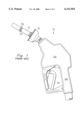
- FIG. 1 is a side elevational view depicting a typical gasoline dispensing and vapor recovery nozzle.
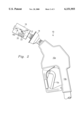
- FIG. 2 is a view similar to FIG. 1, but depicting the nozzle with the test device of the present invention mounted on the spout of the nozzle.
- FIG. 3 is an enlarged elevational view of the test device of FIG. 2.
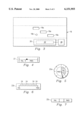
- FIGS. 4-7 are enlarged views of four different displays that can be used with the test device of FIGS. 2 and 3.
- FIG. 1 depicts a prior art fluid dispensing nozzle 10, such as the type used with a gasoline dispenser in a service station for vehicles.
- the nozzle 10 includes a body member 10a, a handle 10b extending from the body member, and a trigger 10c pivotally mounted to the body member which, when pulled back towards the handle, opens a valve, or the like (not shown) in the body member.
- the nozzle 10 would be connected to a source of gasoline which would flow through appropriate passages in the handle 10b and the body member 10a so that the gasoline could be selectively dispensed from the nozzle by actuation of the trigger 10c.
- a discharge spout 12 extends from the body member 10a for insertion into a vehicle tank (not shown) to dispense the gasoline, and a sealing device 14 is provided on the spout for engaging the mouth of the tank to seal the tank during the dispensing operation.
- a plurality of openings 12a are provided through the wall of the spout 12 for receiving vapor from the vehicle tank during the dispensing operation. The vapor is drawn from the vehicle tank, into the interior of the spout 12 through the openings 12a by a vacuum pump (not shown) located downstream from the nozzle 10 and operating at a predetermined RPM.
- hoses are provided in the body member 10a, the handle 10b, and the spout 12 for providing independent flow passages for the gasoline to be dispensed into the vehicle tank and for the recovered vapor to be returned to the storage tank, respectively. Since all of the above components are conventional, they will not be described in further detail.
- a test device according to an embodiment of the present invention is shown by the reference numeral 16 in FIG. 2 mounted on the spout 12 of the nozzle 10. More particularly, the device 16 is in the form of a tubular member that fits over the outer surface of a portion of the spout 12 and is secured thereto in a fairly snug fit.
- the device 16 can be fabricated from plastic, aluminum, or any other suitable material.
- three angularly and axially spaced through slots 16a are provided through the wall of the device 16. At least a portion of the slots 16a register with at least a portion of the openings 12a in the spout 12, with the amount of registration depending on the axial and angular orientation of the device 16 relative to the spout.
- a sensing orifice 16b is also provided through the sleeve and registers with one of the openings 12a in the spout. The function of the orifice 16b will be described later.
- a pressure sensor 20 is mounted on the device 16 for sensing the vacuum in the vapor recovery system and the flow rate of the gasoline from the spout.
- a tube, or the like (not shown) connects the sensing orifice 16a to an input of the sensor 20.
- a pilot tube, or the like, (also not shown) is provided in the spout 12 and is located in a manner to measure the vacuum caused by the gasoline flowing through the spout and is connected to another input of the sensor 20.
- the sensor 20 responds to the above inputs and produces a corresponding output voltage that reflects the vacuum present in the vapor recovery system based on the particular flow rate of the dispensed gasoline.
- a conventional electrical circuit is provided that responds to the latter voltage and actuates a display 22 that is mounted adjacent to, or on the outer face of, the sensor 20.
- the sensor 20 can be of a conventional design, such as a "26 PC Series Pressure Sensor” manufactured by Honeywell, Inc. of Freeport, Ill.
- the display 22 is depicted in detail in FIG. 4 and functions give an indication whether or not the vapor recover system is operating properly based on the output voltage from the sensor 20. More particularly, if the voltage output of the sensor 20 is above the acceptable threshold value, the display 22 will display "Pass”, indicating that the vapor recover system is operating properly. If the voltage output of the sensor 20 is below the acceptable threshold value, the display 22 will display "Fail” indicating that the vapor recover system is not operating properly.
- the spout 12 of the nozzle 10 is placed in the mouth of the gasoline tank of a vehicle, with the sealing device 14 providing a seal.
- the trigger 10c is pulled to dispense the gasoline through one of the hoses, or tubes, in the nozzle 10 and into the tank.
- a vacuum pump is actuated which establishes a vacuum that draws the gasoline vapors from the tank, through the openings 16a and the sensing orifice 16b, and through those portions of the openings 12a in the spout 12 that register with the openings 16a and the orifice 16b.
- the vapors then pass through a dedicated hose extending through the spout 12 and the nozzle 10 and to the gasoline storage tank.
- This vacuum sensed at the orifice 16b is inputted to the sensor 20 along with the flow rate of the gasoline being dispensed from the spout 12 in the manner described above, and the display 22 is actuated accordingly.
- the display 22 indicates a "Pass” condition as discussed above, the operator is assured the system is to specification, while, if a "Fail” condition is indicated, corrective action can be taken.
- FIGS. 5-7 Alternate embodiments of the display 22 are shown in FIGS. 5-7.
- a display 22a is provided which includes a hand that moves around a circle in a manner similar to that of a clock. Indications of "Pass” or “Fail” are provided on the circle to which the hand moves based on the voltage output of the sensor 20.
- the display 22b of the embodiment of FIG. 6 features a plurality of LEDs, or lights, 24 located in a row and adapted to respond to the voltage output of the sensor 20. In this arrangement, if relatively few, or no, lights are lit, a Fail condition exists, while if a relatively large number, or all, of the lights are lit, a Pass condition exists.
- FIG. 7 depicts an analog display 22c which provides a simple indication of Pass or Fail based on the actuation of lights behind the indicia in response to the voltage output of the sensor 20.
- the senor 20 is replaced by a basic vacuum sensor to sense the vacuum in the vapor recover system.
- a comparative circuit 28 (FIG. 3) is provided which compares the sensed vacuum to a predetermined threshold value based on the RPM of the vacuum pump and provides a corresponding output.
- the latter circuit is connected to one of the displays 22-22c to provide the above indications whether or not the vapor recover system is operating properly, in the manners described above.
- the device and method of the above embodiments permit any operator to quickly ascertain whether or not a vapor recovery system is operating properly.
- the device 16 is inexpensive and compact. Further, the flow of the vapor through the registered openings 16a and 12a can be adjusted by simply moving the device 16 angularly and/or axially relative to the spout 12. Also, since the device 16, and its associated display 22 and circuitry, is relatively easy to install, it can be left off of the spout 12 during normal operation of the gasoline dispensing and vapor recovery system and can be installed over the spout when the system is to be tested.
- test device and method of the present invention is not limited to the detection of gasoline vapor in a gasoline dispensing environment, but rather is equally applicable to other similar applications.
- the sensor 20 can be mounted on the nozzle 10 in a manner so that it does not extend in the vehicle tank, in which case it would measure the flow of ambient air that would be induced into the spout through the openings 16a and 12a. This flow measurement by the sensor 20 would be compared to a threshold value based on air flow rather than vapor flow, and the displays 22-22c would provide a corresponding indication.
- present invention is not limit to the specific displays disclosed above but is equally applicable to other displays.
Abstract
Description
Claims (13)
Priority Applications (2)
| Application Number | Priority Date | Filing Date | Title |
|---|---|---|---|
| US09/368,992 US6151955A (en) | 1998-08-07 | 1999-08-05 | Device and method for testing a vapor recovery system |
| PCT/US1999/017902 WO2000008421A1 (en) | 1998-08-07 | 1999-08-06 | Device and method for testing a vapor recovery system |
Applications Claiming Priority (2)
| Application Number | Priority Date | Filing Date | Title |
|---|---|---|---|
| US9572898P | 1998-08-07 | 1998-08-07 | |
| US09/368,992 US6151955A (en) | 1998-08-07 | 1999-08-05 | Device and method for testing a vapor recovery system |
Publications (1)
| Publication Number | Publication Date |
|---|---|
| US6151955A true US6151955A (en) | 2000-11-28 |
Family
ID=26790528
Family Applications (1)
| Application Number | Title | Priority Date | Filing Date |
|---|---|---|---|
| US09/368,992 Expired - Lifetime US6151955A (en) | 1998-08-07 | 1999-08-05 | Device and method for testing a vapor recovery system |
Country Status (2)
| Country | Link |
|---|---|
| US (1) | US6151955A (en) |
| WO (1) | WO2000008421A1 (en) |
Cited By (20)
| Publication number | Priority date | Publication date | Assignee | Title |
|---|---|---|---|---|
| US6532999B2 (en) | 2000-11-16 | 2003-03-18 | Gilbarco Inc. | Pressure sensor for a vapor recovery system |
| US6622757B2 (en) | 1999-11-30 | 2003-09-23 | Veeder-Root Company | Fueling system vapor recovery and containment performance monitor and method of operation thereof |
| US20030230352A1 (en) * | 2002-03-05 | 2003-12-18 | Hart Robert P. | Apparatus and method to control excess pressure in fuel storage containment system at fuel dispensing facilities |
| US6810922B1 (en) | 2003-10-10 | 2004-11-02 | Vapor Systems Technologies, Inc. | Vapor recovery system with improved ORVR compatibility and performance |
| US20050121100A1 (en) * | 2003-12-04 | 2005-06-09 | Eric Riffle | Vapor recovery system with orvr compensation |
| US6948536B1 (en) * | 2002-12-27 | 2005-09-27 | Hirt Combustion Engineers, Inc. | System for detecting liquid fuel blockages in the vapor return line of a fuel dispenser |
| EP1630126A1 (en) * | 2004-08-24 | 2006-03-01 | O'Kane, Michael | Apparatus and method for testing vapor recovery systems |
| WO2006113296A2 (en) * | 2005-04-15 | 2006-10-26 | Healy Systems, Inc. | Fuel delivery nozzle |
| US7159625B1 (en) * | 2005-05-25 | 2007-01-09 | David Klutts | Device for verifying amount of dispensed gasoline and method of use |
| US20070193648A1 (en) * | 2003-10-10 | 2007-08-23 | Grantham Rodger P | Vapor recovery system with improved orvr compatibility and performance |
| WO2010033115A1 (en) * | 2008-09-17 | 2010-03-25 | Franklin Fueling Systems, Inc. | Fuel dispensing nozzle |
| US7909069B2 (en) | 2006-05-04 | 2011-03-22 | Veeder-Root Company | System and method for automatically adjusting an ORVR compatible stage II vapor recovery system to maintain a desired air-to-liquid (A/L) ratio |
| US20110219860A1 (en) * | 2008-09-17 | 2011-09-15 | Franklin Fueling Systems, Inc. | Fuel dispensing nozzle |
| US8167003B1 (en) | 2008-08-19 | 2012-05-01 | Delaware Capital Formation, Inc. | ORVR compatible refueling system |
| US8191585B2 (en) | 2008-05-28 | 2012-06-05 | Franklin Fueling Systems, Inc. | Method and apparatus for monitoring for a restriction in a stage II fuel vapor recovery system |
| US20120168028A1 (en) * | 2009-09-10 | 2012-07-05 | Kumo Industry Co., Ltd. | Oil vapor recovery type fuel dispensing gun |
| US8448675B2 (en) | 2008-05-28 | 2013-05-28 | Franklin Fueling Systems, Inc. | Method and apparatus for monitoring for a restriction in a stage II fuel vapor recovery system |
| US8677805B2 (en) | 2009-05-18 | 2014-03-25 | Franklin Fueling Systems, Inc. | Method and apparatus for detecting a leak in a fuel delivery system |
| US8752597B2 (en) | 2008-09-17 | 2014-06-17 | Franklin Fueling Systems, Inc. | Fuel dispensing nozzle |
| US9604837B2 (en) | 2012-01-06 | 2017-03-28 | Husky Corporation | ORVR valve assembly |
Families Citing this family (1)
| Publication number | Priority date | Publication date | Assignee | Title |
|---|---|---|---|---|
| DE10028542A1 (en) * | 1998-12-29 | 2001-12-13 | Fritz Curtius | Diagnostic system for gas feed in fuel supply in fuel station for vehicles |
Citations (6)
| Publication number | Priority date | Publication date | Assignee | Title |
|---|---|---|---|---|
| US5316057A (en) * | 1993-04-28 | 1994-05-31 | Hasselmann Detlev E M | Vapor recovery system tester |
| US5437183A (en) * | 1992-01-30 | 1995-08-01 | Schlumberger Industries | Method and apparatus for measuring the volumetric efficiency of systems for recovering hydrocarbon vapor |
| US5450883A (en) * | 1994-02-07 | 1995-09-19 | Gilbarco, Inc. | System and method for testing for error conditions in a fuel vapor recovery system |
| US5507325A (en) * | 1993-11-17 | 1996-04-16 | Finlayson; Ian M. | Vapor recovery system for fuel dispensers |
| US5779097A (en) * | 1996-05-14 | 1998-07-14 | Delaware Capital Formation, Inc. | Vapor recovery system with integrated monitoring unit |
| US5871651A (en) * | 1997-04-02 | 1999-02-16 | Gilbarco Inc. | Electronic filter status sensor |
-
1999
- 1999-08-05 US US09/368,992 patent/US6151955A/en not_active Expired - Lifetime
- 1999-08-06 WO PCT/US1999/017902 patent/WO2000008421A1/en active Application Filing
Patent Citations (6)
| Publication number | Priority date | Publication date | Assignee | Title |
|---|---|---|---|---|
| US5437183A (en) * | 1992-01-30 | 1995-08-01 | Schlumberger Industries | Method and apparatus for measuring the volumetric efficiency of systems for recovering hydrocarbon vapor |
| US5316057A (en) * | 1993-04-28 | 1994-05-31 | Hasselmann Detlev E M | Vapor recovery system tester |
| US5507325A (en) * | 1993-11-17 | 1996-04-16 | Finlayson; Ian M. | Vapor recovery system for fuel dispensers |
| US5450883A (en) * | 1994-02-07 | 1995-09-19 | Gilbarco, Inc. | System and method for testing for error conditions in a fuel vapor recovery system |
| US5779097A (en) * | 1996-05-14 | 1998-07-14 | Delaware Capital Formation, Inc. | Vapor recovery system with integrated monitoring unit |
| US5871651A (en) * | 1997-04-02 | 1999-02-16 | Gilbarco Inc. | Electronic filter status sensor |
Cited By (41)
| Publication number | Priority date | Publication date | Assignee | Title |
|---|---|---|---|---|
| US7975528B2 (en) | 1999-11-30 | 2011-07-12 | Veeder-Root Company | Fueling system vapor recovery and containment performance monitor and method of operation thereof |
| US6622757B2 (en) | 1999-11-30 | 2003-09-23 | Veeder-Root Company | Fueling system vapor recovery and containment performance monitor and method of operation thereof |
| US8893542B2 (en) | 1999-11-30 | 2014-11-25 | Veeder-Root Company | Fueling system vapor recovery and containment performance monitor and method of operation thereof |
| US6802344B2 (en) | 1999-11-30 | 2004-10-12 | Veeder-Root Company | Fueling system vapor recovery and containment performance monitor and method of operation thereof |
| US8327689B2 (en) | 1999-11-30 | 2012-12-11 | Veeder-Root Company | Fueling system vapor recovery and containment performance monitor and method of operation thereof |
| US6880585B2 (en) | 1999-11-30 | 2005-04-19 | Veeder-Root Company | Fueling system vapor recovery and containment performance monitor and method of operation thereof |
| US7849728B2 (en) | 1999-11-30 | 2010-12-14 | Veeder-Root Company | Fueling system vapor recovery and containment performance monitor and method of operation thereof |
| US9759631B2 (en) | 1999-11-30 | 2017-09-12 | Veeder-Root Company | Fueling system vapor recovery and containment performance monitor and method of operation thereof |
| US6532999B2 (en) | 2000-11-16 | 2003-03-18 | Gilbarco Inc. | Pressure sensor for a vapor recovery system |
| US6840292B2 (en) | 2002-03-05 | 2005-01-11 | Veeder-Root Company | Apparatus and method to control excess pressure in fuel storage containment system at fuel dispensing facilities |
| US20030230352A1 (en) * | 2002-03-05 | 2003-12-18 | Hart Robert P. | Apparatus and method to control excess pressure in fuel storage containment system at fuel dispensing facilities |
| US7117903B1 (en) | 2002-12-27 | 2006-10-10 | Hirt Combustion | System for detecting liquid fuel blockages in the vapor return line of a fuel dispenser |
| US6948536B1 (en) * | 2002-12-27 | 2005-09-27 | Hirt Combustion Engineers, Inc. | System for detecting liquid fuel blockages in the vapor return line of a fuel dispenser |
| US7174926B1 (en) | 2003-10-10 | 2007-02-13 | Vapor Systems Technologies, Inc. | Vapor recovery system with improved ORVR compatibility and performance |
| US6810922B1 (en) | 2003-10-10 | 2004-11-02 | Vapor Systems Technologies, Inc. | Vapor recovery system with improved ORVR compatibility and performance |
| US7509982B2 (en) | 2003-10-10 | 2009-03-31 | Vapor Systems Technologies, Inc. | Vapor recovery system with improved ORVR compatibility and performance |
| US20070193648A1 (en) * | 2003-10-10 | 2007-08-23 | Grantham Rodger P | Vapor recovery system with improved orvr compatibility and performance |
| US6941978B2 (en) | 2003-12-04 | 2005-09-13 | Gilbarco Inc. | Vapor recovery system with ORVR compensation |
| US20050121100A1 (en) * | 2003-12-04 | 2005-06-09 | Eric Riffle | Vapor recovery system with orvr compensation |
| US20050121101A1 (en) * | 2003-12-04 | 2005-06-09 | Eric Riffle | Vapor recovery system with orvr compensation |
| US6923221B2 (en) | 2003-12-04 | 2005-08-02 | Gilbarco Inc. | Vapor recovery system with ORVR compensation |
| EP1630126A1 (en) * | 2004-08-24 | 2006-03-01 | O'Kane, Michael | Apparatus and method for testing vapor recovery systems |
| WO2006113296A3 (en) * | 2005-04-15 | 2006-12-28 | Healy Systems Inc | Fuel delivery nozzle |
| WO2006113296A2 (en) * | 2005-04-15 | 2006-10-26 | Healy Systems, Inc. | Fuel delivery nozzle |
| US7159625B1 (en) * | 2005-05-25 | 2007-01-09 | David Klutts | Device for verifying amount of dispensed gasoline and method of use |
| US8573262B2 (en) | 2006-05-04 | 2013-11-05 | Veeder-Root Company | System and method for automatically adjusting an ORVR compatible stage II vapor recovery system to maintain a desired air-to-liquid (A/L) ratio |
| US7909069B2 (en) | 2006-05-04 | 2011-03-22 | Veeder-Root Company | System and method for automatically adjusting an ORVR compatible stage II vapor recovery system to maintain a desired air-to-liquid (A/L) ratio |
| US8448675B2 (en) | 2008-05-28 | 2013-05-28 | Franklin Fueling Systems, Inc. | Method and apparatus for monitoring for a restriction in a stage II fuel vapor recovery system |
| US8191585B2 (en) | 2008-05-28 | 2012-06-05 | Franklin Fueling Systems, Inc. | Method and apparatus for monitoring for a restriction in a stage II fuel vapor recovery system |
| US9108837B2 (en) | 2008-05-28 | 2015-08-18 | Franklin Fueling Systems, Inc. | Method and apparatus for monitoring for a restriction in a stage II fuel vapor recovery system |
| US8402817B2 (en) | 2008-05-28 | 2013-03-26 | Franklin Fueling Systems, Inc. | Method and apparatus for monitoring for leaks in a stage II fuel vapor recovery system |
| US8167003B1 (en) | 2008-08-19 | 2012-05-01 | Delaware Capital Formation, Inc. | ORVR compatible refueling system |
| US8752597B2 (en) | 2008-09-17 | 2014-06-17 | Franklin Fueling Systems, Inc. | Fuel dispensing nozzle |
| WO2010033566A3 (en) * | 2008-09-17 | 2010-11-25 | Franklin Fueling Systems, Inc. | Fuel dispensing nozzle |
| US20110219860A1 (en) * | 2008-09-17 | 2011-09-15 | Franklin Fueling Systems, Inc. | Fuel dispensing nozzle |
| WO2010033566A2 (en) * | 2008-09-17 | 2010-03-25 | Franklin Fueling Systems, Inc. | Fuel dispensing nozzle |
| WO2010033115A1 (en) * | 2008-09-17 | 2010-03-25 | Franklin Fueling Systems, Inc. | Fuel dispensing nozzle |
| US8677805B2 (en) | 2009-05-18 | 2014-03-25 | Franklin Fueling Systems, Inc. | Method and apparatus for detecting a leak in a fuel delivery system |
| US10337947B2 (en) | 2009-05-18 | 2019-07-02 | Franklin Fueling Systems, Inc. | Method for detecting a leak in a fuel delivery system |
| US20120168028A1 (en) * | 2009-09-10 | 2012-07-05 | Kumo Industry Co., Ltd. | Oil vapor recovery type fuel dispensing gun |
| US9604837B2 (en) | 2012-01-06 | 2017-03-28 | Husky Corporation | ORVR valve assembly |
Also Published As
| Publication number | Publication date |
|---|---|
| WO2000008421A1 (en) | 2000-02-17 |
| WO2000008421A8 (en) | 2001-02-15 |
Similar Documents
| Publication | Publication Date | Title |
|---|---|---|
| US6151955A (en) | Device and method for testing a vapor recovery system | |
| US5316057A (en) | Vapor recovery system tester | |
| US5450883A (en) | System and method for testing for error conditions in a fuel vapor recovery system | |
| US5507325A (en) | Vapor recovery system for fuel dispensers | |
| EP1037799B1 (en) | Vapor recovery system employing oxygen detection | |
| US6712102B2 (en) | Method and system for preventing vehicle misfuelling | |
| US4167958A (en) | Hydrocarbon fuel dispensing, vapor controlling system | |
| US5363988A (en) | Fuel dispenser controlled in dependence on an electrical signal from a gas detector of the dispenser | |
| US5451927A (en) | Automotive fuel filler pipe cap detection system | |
| WO2001023296A1 (en) | Vapour recovery system with flow rate sensor | |
| US6290760B1 (en) | Air separator system | |
| US6581458B1 (en) | Precalibrated flow meter with airflow compensator | |
| WO2000055047A1 (en) | Vapor recovery system and method with leakage and air flow sensing | |
| US4167957A (en) | Hydrocarbon fuel dispensing, vapor controlling system | |
| US6830080B2 (en) | Output control for turbine vapor flow meter | |
| US5437183A (en) | Method and apparatus for measuring the volumetric efficiency of systems for recovering hydrocarbon vapor | |
| EP0532202B1 (en) | A fuel dispenser | |
| US8196617B2 (en) | Vapor recovery detection means | |
| US7814942B2 (en) | Vapor recovery system for low temperatures | |
| JP3345055B2 (en) | Incorrect lubrication prevention device for lubrication system | |
| JP2001082700A (en) | Leakage detection device | |
| US6038929A (en) | Three-way valved apparatus and method for testing pressure in a fluid system | |
| EP1105343A4 (en) | Coaxial vapor flow indicator | |
| JP3029624B2 (en) | Refueling device | |
| JP2544307B2 (en) | Refueling device |
Legal Events
| Date | Code | Title | Description |
|---|---|---|---|
| AS | Assignment |
Owner name: DRESSER EQUIPMENT GROUP, INC., TEXAS Free format text: ASSIGNMENT OF ASSIGNORS INTEREST;ASSIGNORS:OSTROWSKI, GARY MICHAEL;SMITH, RICHARD MICHAEL;REEL/FRAME:010324/0505 Effective date: 19990923 |
|
| STCF | Information on status: patent grant |
Free format text: PATENTED CASE |
|
| AS | Assignment |
Owner name: MORGAN STANLEY & CO., INCORPORATED, NEW YORK Free format text: SECURITY INTEREST;ASSIGNORS:DRESSER, INC.;DRESSER RE, INC.;DEG ACQUISITIONS, LLC;AND OTHERS;REEL/FRAME:011944/0282 Effective date: 20010410 |
|
| AS | Assignment |
Owner name: DRESSER, INC. (A DELAWARE CORPORATION), TEXAS Free format text: CHANGE OF NAME;ASSIGNOR:DRESSER EQUIPMENT GROUP, INC. (A DELAWARE CORPORATION);REEL/FRAME:012036/0106 Effective date: 20010328 |
|
| FEPP | Fee payment procedure |
Free format text: PAYOR NUMBER ASSIGNED (ORIGINAL EVENT CODE: ASPN); ENTITY STATUS OF PATENT OWNER: LARGE ENTITY |
|
| FPAY | Fee payment |
Year of fee payment: 4 |
|
| AS | Assignment |
Owner name: MORGAN STANLEY & CO. INCORPORATED,NEW YORK Free format text: SECURITY AGREEMENT;ASSIGNORS:DRESSER HOLDINGS, INC.;DRESSER, INC.;DRESSER CHINA, INC.;AND OTHERS;REEL/FRAME:018787/0138 Effective date: 20061031 Owner name: MORGAN STANLEY & CO. INCORPORATED, NEW YORK Free format text: SECURITY AGREEMENT;ASSIGNORS:DRESSER HOLDINGS, INC.;DRESSER, INC.;DRESSER CHINA, INC.;AND OTHERS;REEL/FRAME:018787/0138 Effective date: 20061031 |
|
| AS | Assignment |
Owner name: DRESSER, INC.,TEXAS Free format text: RELEASE BY SECURED PARTY;ASSIGNOR:MORGAN STANLEY & CO. INCORPORATED, AS COLLATERAL AGENT;REEL/FRAME:019489/0077 Effective date: 20070504 Owner name: DEG ACQUISITIONS, LLC,TEXAS Free format text: RELEASE BY SECURED PARTY;ASSIGNOR:MORGAN STANLEY & CO. INCORPORATED, AS COLLATERAL AGENT;REEL/FRAME:019489/0077 Effective date: 20070504 Owner name: DRESSER RE, INC.,TEXAS Free format text: RELEASE BY SECURED PARTY;ASSIGNOR:MORGAN STANLEY & CO. INCORPORATED, AS COLLATERAL AGENT;REEL/FRAME:019489/0077 Effective date: 20070504 Owner name: DRESSER INTERNATIONAL, INC.,TEXAS Free format text: RELEASE BY SECURED PARTY;ASSIGNOR:MORGAN STANLEY & CO. INCORPORATED, AS COLLATERAL AGENT;REEL/FRAME:019489/0077 Effective date: 20070504 Owner name: DRESSER RUSSIA, INC.,TEXAS Free format text: RELEASE BY SECURED PARTY;ASSIGNOR:MORGAN STANLEY & CO. INCORPORATED, AS COLLATERAL AGENT;REEL/FRAME:019489/0077 Effective date: 20070504 Owner name: DRESSER HOLDINGS, INC.,TEXAS Free format text: RELEASE BY SECURED PARTY;ASSIGNOR:MORGAN STANLEY & CO. INCORPORATED, AS COLLATERAL AGENT;REEL/FRAME:019489/0077 Effective date: 20070504 Owner name: DRESSER CHINA, INC.,TEXAS Free format text: RELEASE BY SECURED PARTY;ASSIGNOR:MORGAN STANLEY & CO. INCORPORATED, AS COLLATERAL AGENT;REEL/FRAME:019489/0077 Effective date: 20070504 Owner name: DRESSER ENTECH, INC.,TEXAS Free format text: RELEASE BY SECURED PARTY;ASSIGNOR:MORGAN STANLEY & CO. INCORPORATED, AS COLLATERAL AGENT;REEL/FRAME:019489/0077 Effective date: 20070504 Owner name: LVF HOLDING CORPORATION,TEXAS Free format text: RELEASE BY SECURED PARTY;ASSIGNOR:MORGAN STANLEY & CO. INCORPORATED, AS COLLATERAL AGENT;REEL/FRAME:019489/0077 Effective date: 20070504 Owner name: RING-O VALVE INCORPORATED,TEXAS Free format text: RELEASE BY SECURED PARTY;ASSIGNOR:MORGAN STANLEY & CO. INCORPORATED, AS COLLATERAL AGENT;REEL/FRAME:019489/0077 Effective date: 20070504 Owner name: LVF HOLDING CORPORATION, TEXAS Free format text: RELEASE BY SECURED PARTY;ASSIGNOR:MORGAN STANLEY & CO. INCORPORATED, AS COLLATERAL AGENT;REEL/FRAME:019489/0077 Effective date: 20070504 Owner name: DEG ACQUISITIONS, LLC, TEXAS Free format text: RELEASE BY SECURED PARTY;ASSIGNOR:MORGAN STANLEY & CO. INCORPORATED, AS COLLATERAL AGENT;REEL/FRAME:019489/0077 Effective date: 20070504 Owner name: DRESSER RE, INC., TEXAS Free format text: RELEASE BY SECURED PARTY;ASSIGNOR:MORGAN STANLEY & CO. INCORPORATED, AS COLLATERAL AGENT;REEL/FRAME:019489/0077 Effective date: 20070504 Owner name: DRESSER CHINA, INC., TEXAS Free format text: RELEASE BY SECURED PARTY;ASSIGNOR:MORGAN STANLEY & CO. INCORPORATED, AS COLLATERAL AGENT;REEL/FRAME:019489/0077 Effective date: 20070504 Owner name: LEHMAN COMMERCIAL PAPER INC., AS COLLATERAL AGENT, Free format text: INTELLECTUAL PROPERTY SECOND LIEN SECURITY AGREEMENT;ASSIGNORS:DRESSER INTERMEDIATE HOLDINGS, INC.;CRFRC-D MERGER SUB, INC.;DRESSER, INC.;AND OTHERS;REEL/FRAME:019489/0283 Effective date: 20070504 Owner name: DRESSER HOLDINGS, INC., TEXAS Free format text: RELEASE BY SECURED PARTY;ASSIGNOR:MORGAN STANLEY & CO. INCORPORATED, AS COLLATERAL AGENT;REEL/FRAME:019489/0077 Effective date: 20070504 Owner name: DRESSER RUSSIA, INC., TEXAS Free format text: RELEASE BY SECURED PARTY;ASSIGNOR:MORGAN STANLEY & CO. INCORPORATED, AS COLLATERAL AGENT;REEL/FRAME:019489/0077 Effective date: 20070504 Owner name: DRESSER INTERNATIONAL, INC., TEXAS Free format text: RELEASE BY SECURED PARTY;ASSIGNOR:MORGAN STANLEY & CO. INCORPORATED, AS COLLATERAL AGENT;REEL/FRAME:019489/0077 Effective date: 20070504 Owner name: DRESSER, INC., TEXAS Free format text: RELEASE BY SECURED PARTY;ASSIGNOR:MORGAN STANLEY & CO. INCORPORATED, AS COLLATERAL AGENT;REEL/FRAME:019489/0077 Effective date: 20070504 Owner name: LEHMAN COMMERCIAL PAPER INC., AS COLLATERAL AGENT, Free format text: INTELLECTUAL PROPERTY FIRST LIEN SECURITY AGREEMENT;ASSIGNORS:DRESSER INTERMEDIATE HOLDINGS, INC.;CRFRC-D MERGER SUB, INC.;DRESSER, INC.;AND OTHERS;REEL/FRAME:019489/0178 Effective date: 20070504 Owner name: DRESSER ENTECH, INC., TEXAS Free format text: RELEASE BY SECURED PARTY;ASSIGNOR:MORGAN STANLEY & CO. INCORPORATED, AS COLLATERAL AGENT;REEL/FRAME:019489/0077 Effective date: 20070504 Owner name: RING-O VALVE INCORPORATED, TEXAS Free format text: RELEASE BY SECURED PARTY;ASSIGNOR:MORGAN STANLEY & CO. INCORPORATED, AS COLLATERAL AGENT;REEL/FRAME:019489/0077 Effective date: 20070504 |
|
| FEPP | Fee payment procedure |
Free format text: PAYER NUMBER DE-ASSIGNED (ORIGINAL EVENT CODE: RMPN); ENTITY STATUS OF PATENT OWNER: LARGE ENTITY Free format text: PAYOR NUMBER ASSIGNED (ORIGINAL EVENT CODE: ASPN); ENTITY STATUS OF PATENT OWNER: LARGE ENTITY |
|
| FPAY | Fee payment |
Year of fee payment: 8 |
|
| FEPP | Fee payment procedure |
Free format text: PAYER NUMBER DE-ASSIGNED (ORIGINAL EVENT CODE: RMPN); ENTITY STATUS OF PATENT OWNER: LARGE ENTITY Free format text: PAYOR NUMBER ASSIGNED (ORIGINAL EVENT CODE: ASPN); ENTITY STATUS OF PATENT OWNER: LARGE ENTITY |
|
| AS | Assignment |
Owner name: DRESSER ENTECH, INC., TEXAS Free format text: RELEASE OF FIRST LIEN SECURITY INTEREST IN INTELLECTUAL PROPERTY RECORDED AT REEL/FRAME 19489/178;ASSIGNOR:BARCLAYS BANK PLC, AS SUCCESSOR IN INTEREST TO LEHMAN COMMERCIAL PAPER INC., AS COLLATERAL AGENT;REEL/FRAME:025741/0490 Effective date: 20110201 Owner name: CRFRC-D MERGER SUB, INC., TEXAS Free format text: RELEASE OF SECOND LIEN SECURITY INTEREST IN INTELLECTUAL PROPERTY RECORDED AT REEL/FRAME 19489/283;ASSIGNOR:BARCLAYS BANK PLC, AS SUCCESSOR IN INTEREST TO LEHMAN COMMERCIAL PAPER INC., AS COLLATERAL AGENT;REEL/FRAME:025741/0527 Effective date: 20110201 Owner name: DRESSER, INC., TEXAS Free format text: RELEASE OF SECOND LIEN SECURITY INTEREST IN INTELLECTUAL PROPERTY RECORDED AT REEL/FRAME 19489/283;ASSIGNOR:BARCLAYS BANK PLC, AS SUCCESSOR IN INTEREST TO LEHMAN COMMERCIAL PAPER INC., AS COLLATERAL AGENT;REEL/FRAME:025741/0527 Effective date: 20110201 Owner name: DRESSER INTERNATIONAL, INC., TEXAS Free format text: RELEASE OF SECOND LIEN SECURITY INTEREST IN INTELLECTUAL PROPERTY RECORDED AT REEL/FRAME 19489/283;ASSIGNOR:BARCLAYS BANK PLC, AS SUCCESSOR IN INTEREST TO LEHMAN COMMERCIAL PAPER INC., AS COLLATERAL AGENT;REEL/FRAME:025741/0527 Effective date: 20110201 Owner name: DRESSER RE, INC., TEXAS Free format text: RELEASE OF FIRST LIEN SECURITY INTEREST IN INTELLECTUAL PROPERTY RECORDED AT REEL/FRAME 19489/178;ASSIGNOR:BARCLAYS BANK PLC, AS SUCCESSOR IN INTEREST TO LEHMAN COMMERCIAL PAPER INC., AS COLLATERAL AGENT;REEL/FRAME:025741/0490 Effective date: 20110201 Owner name: DRESSER RE, INC., TEXAS Free format text: RELEASE OF SECOND LIEN SECURITY INTEREST IN INTELLECTUAL PROPERTY RECORDED AT REEL/FRAME 19489/283;ASSIGNOR:BARCLAYS BANK PLC, AS SUCCESSOR IN INTEREST TO LEHMAN COMMERCIAL PAPER INC., AS COLLATERAL AGENT;REEL/FRAME:025741/0527 Effective date: 20110201 Owner name: DRESSER ENTECH, INC., TEXAS Free format text: RELEASE OF SECOND LIEN SECURITY INTEREST IN INTELLECTUAL PROPERTY RECORDED AT REEL/FRAME 19489/283;ASSIGNOR:BARCLAYS BANK PLC, AS SUCCESSOR IN INTEREST TO LEHMAN COMMERCIAL PAPER INC., AS COLLATERAL AGENT;REEL/FRAME:025741/0527 Effective date: 20110201 Owner name: CRFRC-D MERGER SUB, INC., TEXAS Free format text: RELEASE OF FIRST LIEN SECURITY INTEREST IN INTELLECTUAL PROPERTY RECORDED AT REEL/FRAME 19489/178;ASSIGNOR:BARCLAYS BANK PLC, AS SUCCESSOR IN INTEREST TO LEHMAN COMMERCIAL PAPER INC., AS COLLATERAL AGENT;REEL/FRAME:025741/0490 Effective date: 20110201 Owner name: RING-O VALVE, INCORPORATED, TEXAS Free format text: RELEASE OF FIRST LIEN SECURITY INTEREST IN INTELLECTUAL PROPERTY RECORDED AT REEL/FRAME 19489/178;ASSIGNOR:BARCLAYS BANK PLC, AS SUCCESSOR IN INTEREST TO LEHMAN COMMERCIAL PAPER INC., AS COLLATERAL AGENT;REEL/FRAME:025741/0490 Effective date: 20110201 Owner name: DRESSER INTERNATIONAL, INC., TEXAS Free format text: RELEASE OF FIRST LIEN SECURITY INTEREST IN INTELLECTUAL PROPERTY RECORDED AT REEL/FRAME 19489/178;ASSIGNOR:BARCLAYS BANK PLC, AS SUCCESSOR IN INTEREST TO LEHMAN COMMERCIAL PAPER INC., AS COLLATERAL AGENT;REEL/FRAME:025741/0490 Effective date: 20110201 Owner name: DRESSER INTERMEDIATE HOLDINGS, INC., TEXAS Free format text: RELEASE OF SECOND LIEN SECURITY INTEREST IN INTELLECTUAL PROPERTY RECORDED AT REEL/FRAME 19489/283;ASSIGNOR:BARCLAYS BANK PLC, AS SUCCESSOR IN INTEREST TO LEHMAN COMMERCIAL PAPER INC., AS COLLATERAL AGENT;REEL/FRAME:025741/0527 Effective date: 20110201 Owner name: RING-O VALVE, INCORPORATED, TEXAS Free format text: RELEASE OF SECOND LIEN SECURITY INTEREST IN INTELLECTUAL PROPERTY RECORDED AT REEL/FRAME 19489/283;ASSIGNOR:BARCLAYS BANK PLC, AS SUCCESSOR IN INTEREST TO LEHMAN COMMERCIAL PAPER INC., AS COLLATERAL AGENT;REEL/FRAME:025741/0527 Effective date: 20110201 Owner name: DRESSER, INC., TEXAS Free format text: RELEASE OF FIRST LIEN SECURITY INTEREST IN INTELLECTUAL PROPERTY RECORDED AT REEL/FRAME 19489/178;ASSIGNOR:BARCLAYS BANK PLC, AS SUCCESSOR IN INTEREST TO LEHMAN COMMERCIAL PAPER INC., AS COLLATERAL AGENT;REEL/FRAME:025741/0490 Effective date: 20110201 Owner name: DRESSER INTERMEDIATE HOLDINGS, INC., TEXAS Free format text: RELEASE OF FIRST LIEN SECURITY INTEREST IN INTELLECTUAL PROPERTY RECORDED AT REEL/FRAME 19489/178;ASSIGNOR:BARCLAYS BANK PLC, AS SUCCESSOR IN INTEREST TO LEHMAN COMMERCIAL PAPER INC., AS COLLATERAL AGENT;REEL/FRAME:025741/0490 Effective date: 20110201 |
|
| FPAY | Fee payment |
Year of fee payment: 12 |
|
| AS | Assignment |
Owner name: CITIBANK, N.A., AS COLLATERAL AGENT, NEW YORK Free format text: SECURITY INTEREST;ASSIGNOR:WAYNE FUELING SYSTEMS, LLC;REEL/FRAME:033204/0647 Effective date: 20140620 Owner name: CITIBANK, N.A., AS COLLATERAL AGENT, NEW YORK Free format text: SECURITY INTEREST;ASSIGNOR:WAYNE FUELING SYSTEMS, LLC;REEL/FRAME:033204/0680 Effective date: 20140620 |
|
| AS | Assignment |
Owner name: WAYNE FUELING SYSTEMS LLC, TEXAS Free format text: ASSIGNMENT OF ASSIGNORS INTEREST;ASSIGNOR:DRESSER, INC.;REEL/FRAME:033484/0698 Effective date: 20140619 |
|
| AS | Assignment |
Owner name: WAYNE FUELING SYSTEMS LLC, TEXAS Free format text: TERMINATION OF SECURITY INTEREST IN PATENT COLLATERAL (FIRST LIEN - RELEASES RF 033204-0647);ASSIGNOR:CITIBANK, N.A.;REEL/FRAME:041032/0261 Effective date: 20161209 Owner name: WAYNE FUELING SYSTEMS LLC, TEXAS Free format text: TERMINATION OF SECURITY INTEREST IN PATENT COLLATERAL (SECOND LIEN - RELEASES RF 033204-0647);ASSIGNOR:CITIBANK, N.A.;REEL/FRAME:041032/0148 Effective date: 20161209 |