US6151934A - Lock assembly with over-torque defense system - Google Patents
Lock assembly with over-torque defense system Download PDFInfo
- Publication number
- US6151934A US6151934A US09/422,695 US42269599A US6151934A US 6151934 A US6151934 A US 6151934A US 42269599 A US42269599 A US 42269599A US 6151934 A US6151934 A US 6151934A
- Authority
- US
- United States
- Prior art keywords
- spindle
- subassembly
- sleeve
- lockset
- latch bolt
- Prior art date
- Legal status (The legal status is an assumption and is not a legal conclusion. Google has not performed a legal analysis and makes no representation as to the accuracy of the status listed.)
- Expired - Fee Related
Links
- 230000007123 defense Effects 0.000 title description 7
- 230000007246 mechanism Effects 0.000 claims abstract description 79
- 241000220317 Rosa Species 0.000 claims description 22
- 230000008878 coupling Effects 0.000 claims description 5
- 238000010168 coupling process Methods 0.000 claims description 5
- 238000005859 coupling reaction Methods 0.000 claims description 5
- QGZKDVFQNNGYKY-UHFFFAOYSA-N Ammonia Chemical compound N QGZKDVFQNNGYKY-UHFFFAOYSA-N 0.000 description 2
- 230000001965 increasing effect Effects 0.000 description 2
- 229910021529 ammonia Inorganic materials 0.000 description 1
- 239000010960 cold rolled steel Substances 0.000 description 1
- 230000000295 complement effect Effects 0.000 description 1
- 239000002537 cosmetic Substances 0.000 description 1
- 230000002708 enhancing effect Effects 0.000 description 1
- 230000002401 inhibitory effect Effects 0.000 description 1
- 239000000463 material Substances 0.000 description 1
- 238000000034 method Methods 0.000 description 1
- 238000012986 modification Methods 0.000 description 1
- 230000004048 modification Effects 0.000 description 1
- 230000002093 peripheral effect Effects 0.000 description 1
Images
Classifications
-
- E—FIXED CONSTRUCTIONS
- E05—LOCKS; KEYS; WINDOW OR DOOR FITTINGS; SAFES
- E05B—LOCKS; ACCESSORIES THEREFOR; HANDCUFFS
- E05B17/00—Accessories in connection with locks
- E05B17/0054—Fraction or shear lines; Slip-clutches, resilient parts or the like for preventing damage when forced or slammed
- E05B17/0062—Fraction or shear lines; Slip-clutches, resilient parts or the like for preventing damage when forced or slammed with destructive disengagement
-
- E—FIXED CONSTRUCTIONS
- E05—LOCKS; KEYS; WINDOW OR DOOR FITTINGS; SAFES
- E05B—LOCKS; ACCESSORIES THEREFOR; HANDCUFFS
- E05B13/00—Devices preventing the key or the handle or both from being used
- E05B13/10—Devices preventing the key or the handle or both from being used formed by a lock arranged in the handle
- E05B13/106—Devices preventing the key or the handle or both from being used formed by a lock arranged in the handle for handles pivoted about an axis perpendicular to the wing
- E05B13/108—Devices preventing the key or the handle or both from being used formed by a lock arranged in the handle for handles pivoted about an axis perpendicular to the wing the lock coaxial with spindle
-
- E—FIXED CONSTRUCTIONS
- E05—LOCKS; KEYS; WINDOW OR DOOR FITTINGS; SAFES
- E05B—LOCKS; ACCESSORIES THEREFOR; HANDCUFFS
- E05B17/00—Accessories in connection with locks
- E05B17/20—Means independent of the locking mechanism for preventing unauthorised opening, e.g. for securing the bolt in the fastening position
- E05B17/2084—Means to prevent forced opening by attack, tampering or jimmying
-
- E—FIXED CONSTRUCTIONS
- E05—LOCKS; KEYS; WINDOW OR DOOR FITTINGS; SAFES
- E05B—LOCKS; ACCESSORIES THEREFOR; HANDCUFFS
- E05B63/00—Locks or fastenings with special structural characteristics
- E05B63/16—Locks or fastenings with special structural characteristics with the handles on opposite sides moving independently
-
- Y—GENERAL TAGGING OF NEW TECHNOLOGICAL DEVELOPMENTS; GENERAL TAGGING OF CROSS-SECTIONAL TECHNOLOGIES SPANNING OVER SEVERAL SECTIONS OF THE IPC; TECHNICAL SUBJECTS COVERED BY FORMER USPC CROSS-REFERENCE ART COLLECTIONS [XRACs] AND DIGESTS
- Y10—TECHNICAL SUBJECTS COVERED BY FORMER USPC
- Y10T—TECHNICAL SUBJECTS COVERED BY FORMER US CLASSIFICATION
- Y10T70/00—Locks
- Y10T70/50—Special application
- Y10T70/5093—For closures
- Y10T70/5155—Door
- Y10T70/5199—Swinging door
- Y10T70/5372—Locking latch bolts, biased
- Y10T70/5385—Spring projected
- Y10T70/5389—Manually operable
- Y10T70/5394—Directly acting dog for exterior, manual, bolt manipulator
- Y10T70/5416—Exterior manipulator declutched from bolt when dogged
-
- Y—GENERAL TAGGING OF NEW TECHNOLOGICAL DEVELOPMENTS; GENERAL TAGGING OF CROSS-SECTIONAL TECHNOLOGIES SPANNING OVER SEVERAL SECTIONS OF THE IPC; TECHNICAL SUBJECTS COVERED BY FORMER USPC CROSS-REFERENCE ART COLLECTIONS [XRACs] AND DIGESTS
- Y10—TECHNICAL SUBJECTS COVERED BY FORMER USPC
- Y10T—TECHNICAL SUBJECTS COVERED BY FORMER US CLASSIFICATION
- Y10T70/00—Locks
- Y10T70/50—Special application
- Y10T70/5611—For control and machine elements
- Y10T70/5757—Handle, handwheel or knob
- Y10T70/5765—Rotary or swinging
- Y10T70/5805—Freely movable when locked
- Y10T70/5819—Handle-carried key lock
-
- Y—GENERAL TAGGING OF NEW TECHNOLOGICAL DEVELOPMENTS; GENERAL TAGGING OF CROSS-SECTIONAL TECHNOLOGIES SPANNING OVER SEVERAL SECTIONS OF THE IPC; TECHNICAL SUBJECTS COVERED BY FORMER USPC CROSS-REFERENCE ART COLLECTIONS [XRACs] AND DIGESTS
- Y10—TECHNICAL SUBJECTS COVERED BY FORMER USPC
- Y10T—TECHNICAL SUBJECTS COVERED BY FORMER US CLASSIFICATION
- Y10T70/00—Locks
- Y10T70/50—Special application
- Y10T70/5611—For control and machine elements
- Y10T70/5757—Handle, handwheel or knob
- Y10T70/5832—Lock and handle assembly
-
- Y—GENERAL TAGGING OF NEW TECHNOLOGICAL DEVELOPMENTS; GENERAL TAGGING OF CROSS-SECTIONAL TECHNOLOGIES SPANNING OVER SEVERAL SECTIONS OF THE IPC; TECHNICAL SUBJECTS COVERED BY FORMER USPC CROSS-REFERENCE ART COLLECTIONS [XRACs] AND DIGESTS
- Y10—TECHNICAL SUBJECTS COVERED BY FORMER USPC
- Y10T—TECHNICAL SUBJECTS COVERED BY FORMER US CLASSIFICATION
- Y10T70/00—Locks
- Y10T70/70—Operating mechanism
- Y10T70/7441—Key
- Y10T70/7915—Tampering prevention or attack defeating
- Y10T70/7949—Yielding or frangible connections
Definitions
- the present invention relates generally to a lockset mechanism adapted to provide a torque-releasable knob for defeating a forced entry attack, and more particularly to a lockset mechanism having a spindle subassembly operable in an enabled mode wherein a handle subassembly is operably coupled to a latch bolt subassembly through the spindle subassembly for normal actuation of the lockset mechanism and a disabled mode wherein the handle subassembly is uncoupled from the latch subassembly as a result of an over-torque force having been applied to the spindle subassembly causing it to fracture.
- a variety of door lockset mechanisms operable for selectively closing and locking a door are generally known in the art.
- the door knob is mounted on a knob sleeve or spindle which is adapted to be blocked from rotation by manipulation of a turn mechanism or the like operably mounted on the knob, thus preventing operation of the latch bolt subassembly.
- the outside door knob may incorporate a key-actuated lock mechanism for actuating the locking mechanism.
- One method of forced entry attack on such lockset mechanism is to apply a high turning force or over-torque on the outside knob, as with a pipe wrench or other tool, sufficient to break or overpower the mechanism which blocks the knob spindle from rotation, thereby actuating the knob sleeve to retract the latch bolt.
- a preferred embodiment of the lockset mechanism includes a spindle subassembly having a full-round spindle mounted within a half-round spindle.
- the half-round spindle is drivingly connected to a sleeve, which in turn is drivingly connected to a handle subassembly.
- the sleeve, half-round spindle and full-round spindle are free to rotate within the lockset housing such that the half-round spindle actuates a latch bolt.
- the spindle subassembly When the lockset mechanism is in the locked condition, the spindle subassembly is constrained from rotation by means of a locking slide which connects the spindle subassembly to the lockset housing.
- the half-round spindle Upon application of an over-torque to the handle subassembly, the half-round spindle will fracture, and a spring operably coupled between the lockset housing and the spindle subassembly urges the full-round spindle out of driving engagement with the handle subassembly.
- the spindle subassembly is disabled and the handle subassembly is uncoupled from the latch bolt subassembly.
- the defense system of the present invention will not operate the latch and the handle subassembly will otherwise spin freely.
- a lockset mechanism having a spindle subassembly operable in an enabled mode whereby the handle subassembly is operably coupled to the latch bolt subassembly, and further operable in a disengaged mode when an over-torque has been applied to the handle subassembly for uncoupling the connection with the latch bolt subassembly.
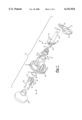
- FIG. 1 is an exploded perspective view of a portion of the lockset mechanism including the spindle subassembly in accordance with the present invention
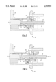
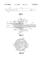
- FIG. 2 is a transverse cross-section of a lockset mechanism illustrating the spindle subassembly in an enabled mode
- FIG. 3 is a transverse cross-sectional view of the lockset mechanism shown in FIG. 2, with the exception that the spindle subassembly is in a disabled mode;
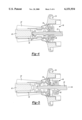
- FIG. 4 is a vertical cross-sectional view of the lockset mechanism illustrated in FIG. 2;
- FIG. 5 is a vertical cross-sectional view of the lockset mechanism illustrated in FIG. 3;
- FIG. 6 is a detailed cross-sectional view showing the interface between the spindle subassembly and a portion of the lockset housing;
- FIG. 7 is a detailed cross-sectional view showing the interface between the spindle subassembly and the handle subassembly;
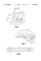
- FIG. 8 is a detailed plan view showing the half-round spindle of the present invention.
- FIG. 9 is a partial cross-sectional view showing the half-round spindle
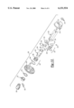
- FIG. 10 is an exploded perspective view of a second preferred embodiment of the present invention.
- FIG. 11 is a transverse cross-section of the second preferred embodiment illustrated in FIG. 10.
- FIG. 12 is a cross-section taken along the line XII--XII shown in FIG. 11.
- lockset mechanism 20 having handle subassembly 22, spindle subassembly 24 and latch bolt subassembly 26.
- Handle subassembly 22 includes knob 28 secured to exterior sleeve 30 for rotation therewith. Exterior sleeve 30 is received within a central aperture formed in exterior rose 32 and releasably secured therein by support washer 34 such that knob 28 and exterior sleeve 30 are rotatably supported within exterior rose 32.
- Exterior rose 32 includes rose liner 36 and rose cover 38 releasably secured over rose liner 36 for providing a finished cosmetic appearance.
- knob 28 may be of any conventional design including a generally spherical knob as illustrated in FIG. 1, a lever-type knob as illustrated in FIGS. 2 and 3 or alternately any other suitable shape.
- knob 28 is adapted to receive a keyed lock cylinder 40 operably coupled to spindle subassembly 24 for selectively locking and unlocking lockset mechanism 20.
- Spindle subassembly 24 includes full-round spindle 42 and half-round spindle 44 operably coupling handle subassembly 22 with latch bolt subassembly 26.
- Torsion spring mechanism 46 includes torsion spring 48 operably coupled between half-round spindle 44 and rose liner 36 for providing a biased return torque for maintaining latch bolt subassembly 26 in an extended position.
- Torsion spring mechanism 46 further includes locking slide 50 operably coupled to full-round spindle 42 and slidably positionable upon rotation of full-round spindle 42 between a locked condition wherein slide 50 engages the housing for disabling rotation of spindle subassembly 24 and an unlocked condition for disengaging the housing to permit rotation of spindle subassembly 24.
- Full-round spindle 42 and half-round spindle 44 are received in an aperture 52 formed in latch bolt subassembly 26.
- Half-round spindle 44 is operably coupled to latch bolt 54 such that rotation of handle subassembly 22 actuates latch bolt subassembly 26 for movement between an extended position and a retracted position.
- full-round spindle 42 is operably coupled to lock cylinder 40 such that rotation of a keyed member in lock cylinder 40 rotates full-round spindle 42 causing slide 50 to move between the locked and unlocked state.
- the end of fullround spindle 42 opposite exterior end 56 may be adapted to receive a lock turn mechanism operably associated with an interior knob assembly (not shown) of lockset mechanism 20 for manipulating slide 50 between the locked and unlocked state.
- Half-round spindle 44 is operably coupled to exterior sleeve 30 for co-rotation therewith.
- exterior sleeve 30 has a tab 58 projecting inwardly therefrom which is received within a slot 60 formed in half-round spindle 44. In this manner, tab 58 axially positions and rotatably couples half-round spindle 44 with exterior sleeve 30.
- lockset mechanism 20 is provided with an over-torque defense system which disables the lockset mechanism when an over-torque force has been applied thereto.
- half-round spindle 44 is designed to fracture when an actuation torque has been applied to handle subassembly 22 which exceeds a maximum torque. More specifically, half-round spindle 44 may be provided with certain design features which initiate a fracture thereof when the maximum torque has been exceeded. For example, as best seen in FIGS. 8 and 9, a pair of notches 62 are formed at an end of half-round spindle 44 adjacent slot 60.
- Notches 62 locally reduce the cross-sectional area of half-round spindle 44, as well as function as a stress riser to locate and control the failure mode of half-round spindle 44.
- notches 62 are formed at the edges of half-round spindle 44 and have a generally circular configuration.
- stress risers may be adapted to the present invention to provide a particular failure mode of half-round spindle 44.
- Half-round spindle 44 may also be heat treated in a manner such that the hardness of the material, typically soft cold-rolled steel, is increased.
- half-round spindle 44 may be heat treated in the presence of ammonia such that it becomes case hardened (from a hardness of approximately 60 RB to approximately 30-40 RC) and brittle.
- the failure mode of half-round spindle 44 at the maximum torque force may be precisely controlled.
- maximum torque in the range of 220-270 inchpounds is preferred and a maximum torque in the range of 240-250 inch-pounds is more preferred to provide an adequate over-torque defense system.
- the precise maximum torque range may be a function of the particular design and application of the lockset mechanism.
- spindle subassembly 24 includes spring mechanism 64 operably coupled between rose liner 36 and torque spring mechanism 46 for urging spindle subassembly 24 axially away from exterior rose 32.
- Spring mechanism 64 includes spring seat 66 positioned adjacent the interior end 68 of exterior sleeve 30.
- a series of prongs 70 extend axially from exterior sleeve 30 and engage recesses 72 formed in spring seat 66.
- Conical coil spring 74 is operably disposed between spring seat 66 and torque spring mechanism 46 to generate an axial biasing force.
- coil spring 74 normally biases spindle subassembly 24 away from handle subassembly 22 such that when half-round spindle 44 fractures due to the application of an over-torque to handle subassembly 22, coil spring 74 forces full-round spindle 42 away from handle subassembly 22 and out of driving engagement with lock cylinder 40.
- full-round spindle 42 is no longer in driving engagement with lock cylinder 40 and a portion of half-round spindle 44 and torsion spring mechanism 46 move axially away from handle subassembly 22 in the direction of arrow A shown in FIGS. 3 and 5.
- spindle subassembly 24 is fully disabled. In this disabled state, handle subassembly 22 freely spins and the locking mechanism of lockset 20 is protected. While a conical coil spring is presently preferred, one skilled in the art will readily recognize that other biasing means such as a helical coil spring, a wave washer, a spring washer or other equivalent mechanisms for generating an axial biasing force may be utilized for urging spindle subassembly 24 away from handle subassembly 22.
- biasing means such as a helical coil spring, a wave washer, a spring washer or other equivalent mechanisms for generating an axial biasing force may be utilized for urging spindle subassembly 24 away from handle subassembly 22.
- Lockset mechanism 120 includes handle subassembly 122 and spindle subassembly 124 which is operably coupled to a latch bolt subassembly (not shown). Lockset mechanism 120 is particularly adapted to include a low-cost over-torque defense system similar to that incorporated in lockset mechanism 20 previously described. More specifically, spindle subassembly 124 includes full-round spindle 126 and half-round spindle 128 operably disposed within torque spring mechanism 130 which includes torsion spring 132, locking slide members 134, 136 and torsion spring housing 138.
- Full-round spindle 126 is operably coupled to locking slide 136 such that rotation of full-round spindle 126 moves locking slide 136 in the transverse direction from an unlocked condition to a locked condition for inhibiting rotation of spindle subassembly 124 to disable the latch bolt subassembly.
- Full-round spindle 126 is operably coupled at the end adjacent handle subassembly 122 to lock cylinder 140.
- the interior end of full-round spindle 126 is operably coupled to a turn mechanism operably associated with the interior handle subassembly (not shown).
- Half-round spindle 128 is operably coupled to exterior handle subassembly 122 for rotation therewith. More specifically, the exterior end of half-round spindle 128 is received within exterior sleeve 142. Insert 144 having a complementary surface 146 to half-round spindle 128 is also inserted within exterior sleeve 142. A pair of radially extending details 148 are formed on insert 144 and adapted to engage the edges of half-round spindle 128. Details 148 are also received within slot 150 formed in the end of exterior sleeve 142. In this manner, half-round spindle 128, exterior sleeve 142 and insert 144 are coupled together for co-rotation. As best seen in FIG.
- exterior sleeve 142 has an inwardly extending tab 152 formed thereon which is adapted to be received within slot 154 of half-round spindle 128.
- tab 156 formed on exterior sleeve 142 extends into groove 158 formed in insert 144.
- details 148 operably couple half-round spindle 128, exterior sleeve 142 and insert 144 for co-rotation while tabs 152, 156 fix these components axially.
- half-round spindle 128 is provided with certain design features which cause half-round spindle 128 to fracture when an over-torque force has been applied to lockset mechanism 120. More specifically, notches 160 are formed in the peripheral edges of half-round spindle 128 adjacent slot 154. In addition, half-round spindle 128 may be heat treated to provide a desired range of hardness, thereby increasing its brittleness. In this manner, half-round spindle 128 is particularly adapted to fracture at a location adjacent notches 160 when the over-torque force is applied.
- spindle subassembly 124 further includes spring mechanism 162 operably disposed between rose liner 164 and torsion spring mechanism 130 for biasing spindle subassembly 124 away from exterior handle subassembly 122.
- Spring mechanism 162 includes spring seat 166 engaging an inner surface of rose liner 164 and helical coil spring 168 operably disposed between spring seat 166 and torsion spring housing 138.
- half-round spindle 128 fractures adjacent notches 160.
- Spring mechanism 162 urges full-round spindle 126 away from exterior handle subassembly 122 such that the exterior end thereof disengages lock cylinder 140, thereby disabling spindle subassembly 124.
- spindle subassembly 124 is rotatably supported by rose liner 164 at a side opposite exterior handle subassembly 122. More specifically, rose shield 170 extends axially inwardly from rose liner 164 and has a central aperture 172 formed therein which is adapted to receive bearing member 174. Full-round spindle 126 and half-round spindle 128 extend through a central portion of bearing member 174 and are rotatably supported by rose shield 170. Support collar 176 and washer 178 are operably disposed between the exterior knob (not shown) of handle subassembly 122 and rose liner 164 for enhancing the relative rotation therebetween. As best seen in FIG. 11, handle subassembly 122 further includes spring member 180 secured within exterior sleeve 142 and operably coupled to catch member 182 for retaining and rotatably coupling a knob with exterior sleeve 142.
Abstract
Description
Claims (11)
Priority Applications (8)
| Application Number | Priority Date | Filing Date | Title |
|---|---|---|---|
| US09/422,695 US6151934A (en) | 1998-10-23 | 1999-10-21 | Lock assembly with over-torque defense system |
| BR9914751A BR9914751A (en) | 1998-10-23 | 1999-10-22 | Lock assembly with excessive torque defense system |
| GB0110231A GB2359334B (en) | 1998-10-23 | 1999-10-22 | Lock assembly with over-torque defense system |
| AU12225/00A AU1222500A (en) | 1998-10-23 | 1999-10-22 | Lock assembly with over-torque defense system |
| JP2000578538A JP2003526749A (en) | 1998-10-23 | 1999-10-22 | Lock assembly with overtorque protection system |
| CA 2348791 CA2348791C (en) | 1998-10-23 | 1999-10-22 | Lock assembly with over-torque defense system |
| CNB998138134A CN1154777C (en) | 1998-10-23 | 1999-10-22 | Lock assembly with over-torque defense system |
| PCT/US1999/024808 WO2000024993A1 (en) | 1998-10-23 | 1999-10-22 | Lock assembly with over-torque defense system |
Applications Claiming Priority (2)
| Application Number | Priority Date | Filing Date | Title |
|---|---|---|---|
| US10545798P | 1998-10-23 | 1998-10-23 | |
| US09/422,695 US6151934A (en) | 1998-10-23 | 1999-10-21 | Lock assembly with over-torque defense system |
Publications (1)
| Publication Number | Publication Date |
|---|---|
| US6151934A true US6151934A (en) | 2000-11-28 |
Family
ID=26802602
Family Applications (1)
| Application Number | Title | Priority Date | Filing Date |
|---|---|---|---|
| US09/422,695 Expired - Fee Related US6151934A (en) | 1998-10-23 | 1999-10-21 | Lock assembly with over-torque defense system |
Country Status (8)
| Country | Link |
|---|---|
| US (1) | US6151934A (en) |
| JP (1) | JP2003526749A (en) |
| CN (1) | CN1154777C (en) |
| AU (1) | AU1222500A (en) |
| BR (1) | BR9914751A (en) |
| CA (1) | CA2348791C (en) |
| GB (1) | GB2359334B (en) |
| WO (1) | WO2000024993A1 (en) |
Cited By (26)
| Publication number | Priority date | Publication date | Assignee | Title |
|---|---|---|---|---|
| US6279360B1 (en) * | 1999-08-17 | 2001-08-28 | Shen Mu-Lin | Cylindrical lock with simpler positioning assembly |
| US6357270B1 (en) * | 1999-09-08 | 2002-03-19 | Scovill Locks, S.A. De C.V. | Free-wheeling door lock mechanism |
| US6425273B1 (en) * | 1998-12-22 | 2002-07-30 | Dae Young Kim | Tubular lever lock |
| US6468310B1 (en) * | 2001-07-16 | 2002-10-22 | Third Millennium Engineering, Llc | Intervertebral spacer device having a wave washer force restoring element |
| US6615630B2 (en) * | 2000-12-05 | 2003-09-09 | Tong-Lung Metal Industry Co., Ltd. | Door lock |
| US20040074269A1 (en) * | 2002-10-21 | 2004-04-22 | Lee Han Young | Anti-break cylindrical lever lock |
| US6742367B2 (en) * | 2002-08-19 | 2004-06-01 | Taiwan Fu Hsing Industrial Co., Ltd | Inside locking device of flat handle lock |
| US20040236426A1 (en) * | 2001-07-16 | 2004-11-25 | Ralph James D. | Artificial intervertebral disc having a wave washer force restoring element |
| US6979029B2 (en) | 2003-12-10 | 2005-12-27 | Shen Mu-Lin | Lock with increased torque-resisting capacity |
| US7618455B2 (en) | 2000-12-13 | 2009-11-17 | Facet Solutions, Inc | Multiple facet joint replacement |
| US7722647B1 (en) | 2005-03-14 | 2010-05-25 | Facet Solutions, Inc. | Apparatus and method for posterior vertebral stabilization |
| US7753937B2 (en) | 2003-12-10 | 2010-07-13 | Facet Solutions Inc. | Linked bilateral spinal facet implants and methods of use |
| US7815648B2 (en) | 2004-06-02 | 2010-10-19 | Facet Solutions, Inc | Surgical measurement systems and methods |
| US7955390B2 (en) | 2001-03-02 | 2011-06-07 | GME Delaware 2 LLC | Method and apparatus for spine joint replacement |
| US7993373B2 (en) | 2005-02-22 | 2011-08-09 | Hoy Robert W | Polyaxial orthopedic fastening apparatus |
| US8206418B2 (en) | 2007-01-10 | 2012-06-26 | Gmedelaware 2 Llc | System and method for facet joint replacement with detachable coupler |
| US8313511B2 (en) | 2000-11-29 | 2012-11-20 | Gmedelaware 2 Llc | Facet joint replacement |
| US8556936B2 (en) | 2000-11-29 | 2013-10-15 | Gmedelaware 2 Llc | Facet joint replacement |
| US8562649B2 (en) | 2004-02-17 | 2013-10-22 | Gmedelaware 2 Llc | System and method for multiple level facet joint arthroplasty and fusion |
| US8764801B2 (en) | 2005-03-28 | 2014-07-01 | Gmedelaware 2 Llc | Facet joint implant crosslinking apparatus and method |
| US20140196566A1 (en) * | 2013-01-17 | 2014-07-17 | Taiwan Fu Hsing Industrial Co., Ltd. | Rotation assembly |
| US20140196509A1 (en) * | 2013-01-15 | 2014-07-17 | Townsteel, Inc. | Attack-Thwarting Cylindrical Lockset |
| US8900273B2 (en) | 2005-02-22 | 2014-12-02 | Gmedelaware 2 Llc | Taper-locking fixation system |
| CN104631914A (en) * | 2014-01-29 | 2015-05-20 | 广州国保科技有限公司 | Lock cylinder with slipping mechanism |
| US20150167360A1 (en) * | 2013-12-18 | 2015-06-18 | Hyundai Motor Company | Door lock device for vehicle |
| US9528300B2 (en) | 2012-03-14 | 2016-12-27 | Townsteel, Inc. | Cylindrical lockset |
Families Citing this family (6)
| Publication number | Priority date | Publication date | Assignee | Title |
|---|---|---|---|---|
| US6908126B2 (en) * | 2002-10-15 | 2005-06-21 | Sargent Manufacturing Company | Enhanced security catch assembly for retaining a handle on a spindle |
| CN102061834B (en) * | 2010-12-31 | 2013-01-23 | 吕思农 | Rotating disc type adjusting structure for handle torque |
| CN104790761A (en) * | 2014-01-22 | 2015-07-22 | 陈慧兰 | Double-safety lock latch structure |
| KR101578774B1 (en) * | 2014-10-24 | 2015-12-18 | 주식회사 유니락 | A Electronic Type of Locking Device Having Cylinder Structure |
| GB201705601D0 (en) * | 2017-04-07 | 2017-05-24 | Patlock Design Ltd | Spindle apparatus and method of use thereof |
| KR102042596B1 (en) * | 2019-01-18 | 2019-11-08 | 동성산업 주식회사 | Door lock for fire doors |
Citations (8)
| Publication number | Priority date | Publication date | Assignee | Title |
|---|---|---|---|---|
| US2063708A (en) * | 1935-04-12 | 1936-12-08 | Swilens Charles | Lock |
| US2138856A (en) * | 1933-04-17 | 1938-12-06 | Frank E Best Inc | Lock |
| US2609679A (en) * | 1949-07-22 | 1952-09-09 | Mosler Safe Co | Safe lock |
| US4195502A (en) * | 1978-06-02 | 1980-04-01 | Best Lock Corporation | Break-away door knob |
| US4426858A (en) * | 1981-06-01 | 1984-01-24 | Bruno Interrante | Tamper deactivating assembly |
| US4550581A (en) * | 1981-06-05 | 1985-11-05 | Best Lock Corporation | Break-away knob driver |
| US4589691A (en) * | 1984-05-04 | 1986-05-20 | Best Lock Corporation | Lever handle mortise lock |
| US4667994A (en) * | 1986-02-06 | 1987-05-26 | Best Lock Corporation | Frangible spindle |
-
1999
- 1999-10-21 US US09/422,695 patent/US6151934A/en not_active Expired - Fee Related
- 1999-10-22 CN CNB998138134A patent/CN1154777C/en not_active Expired - Fee Related
- 1999-10-22 GB GB0110231A patent/GB2359334B/en not_active Expired - Fee Related
- 1999-10-22 BR BR9914751A patent/BR9914751A/en not_active Application Discontinuation
- 1999-10-22 AU AU12225/00A patent/AU1222500A/en not_active Abandoned
- 1999-10-22 CA CA 2348791 patent/CA2348791C/en not_active Expired - Fee Related
- 1999-10-22 WO PCT/US1999/024808 patent/WO2000024993A1/en not_active Application Discontinuation
- 1999-10-22 JP JP2000578538A patent/JP2003526749A/en active Pending
Patent Citations (8)
| Publication number | Priority date | Publication date | Assignee | Title |
|---|---|---|---|---|
| US2138856A (en) * | 1933-04-17 | 1938-12-06 | Frank E Best Inc | Lock |
| US2063708A (en) * | 1935-04-12 | 1936-12-08 | Swilens Charles | Lock |
| US2609679A (en) * | 1949-07-22 | 1952-09-09 | Mosler Safe Co | Safe lock |
| US4195502A (en) * | 1978-06-02 | 1980-04-01 | Best Lock Corporation | Break-away door knob |
| US4426858A (en) * | 1981-06-01 | 1984-01-24 | Bruno Interrante | Tamper deactivating assembly |
| US4550581A (en) * | 1981-06-05 | 1985-11-05 | Best Lock Corporation | Break-away knob driver |
| US4589691A (en) * | 1984-05-04 | 1986-05-20 | Best Lock Corporation | Lever handle mortise lock |
| US4667994A (en) * | 1986-02-06 | 1987-05-26 | Best Lock Corporation | Frangible spindle |
Cited By (46)
| Publication number | Priority date | Publication date | Assignee | Title |
|---|---|---|---|---|
| US6425273B1 (en) * | 1998-12-22 | 2002-07-30 | Dae Young Kim | Tubular lever lock |
| US6279360B1 (en) * | 1999-08-17 | 2001-08-28 | Shen Mu-Lin | Cylindrical lock with simpler positioning assembly |
| US6357270B1 (en) * | 1999-09-08 | 2002-03-19 | Scovill Locks, S.A. De C.V. | Free-wheeling door lock mechanism |
| US8313511B2 (en) | 2000-11-29 | 2012-11-20 | Gmedelaware 2 Llc | Facet joint replacement |
| US8556936B2 (en) | 2000-11-29 | 2013-10-15 | Gmedelaware 2 Llc | Facet joint replacement |
| US6615630B2 (en) * | 2000-12-05 | 2003-09-09 | Tong-Lung Metal Industry Co., Ltd. | Door lock |
| US7618455B2 (en) | 2000-12-13 | 2009-11-17 | Facet Solutions, Inc | Multiple facet joint replacement |
| US7955390B2 (en) | 2001-03-02 | 2011-06-07 | GME Delaware 2 LLC | Method and apparatus for spine joint replacement |
| US20040204763A1 (en) * | 2001-07-16 | 2004-10-14 | Ralph James D | Intervertebral spacer device having a wave washer force restoring element |
| US20040236426A1 (en) * | 2001-07-16 | 2004-11-25 | Ralph James D. | Artificial intervertebral disc having a wave washer force restoring element |
| US7314486B2 (en) | 2001-07-16 | 2008-01-01 | Spinecore, Inc. | Artificial intervertebral disc having a wave washer force restoring element |
| US7314487B2 (en) | 2001-07-16 | 2008-01-01 | Spinecore, Inc. | Intervertebral spacer device having a wave washer force restoring element |
| US6468310B1 (en) * | 2001-07-16 | 2002-10-22 | Third Millennium Engineering, Llc | Intervertebral spacer device having a wave washer force restoring element |
| US6742367B2 (en) * | 2002-08-19 | 2004-06-01 | Taiwan Fu Hsing Industrial Co., Ltd | Inside locking device of flat handle lock |
| US20040074269A1 (en) * | 2002-10-21 | 2004-04-22 | Lee Han Young | Anti-break cylindrical lever lock |
| US6979029B2 (en) | 2003-12-10 | 2005-12-27 | Shen Mu-Lin | Lock with increased torque-resisting capacity |
| US7753937B2 (en) | 2003-12-10 | 2010-07-13 | Facet Solutions Inc. | Linked bilateral spinal facet implants and methods of use |
| US8419770B2 (en) | 2003-12-10 | 2013-04-16 | Gmedelaware 2 Llc | Spinal facet implants with mating articulating bearing surface and methods of use |
| US8926700B2 (en) | 2003-12-10 | 2015-01-06 | Gmedelware 2 LLC | Spinal facet joint implant |
| US7914560B2 (en) | 2004-02-17 | 2011-03-29 | Gmedelaware 2 Llc | Spinal facet implant with spherical implant apposition surface and bone bed and methods of use |
| US7998177B2 (en) | 2004-02-17 | 2011-08-16 | Gmedelaware 2 Llc | Linked bilateral spinal facet implants and methods of use |
| US7998178B2 (en) | 2004-02-17 | 2011-08-16 | Gmedelaware 2 Llc | Linked bilateral spinal facet implants and methods of use |
| US8906063B2 (en) | 2004-02-17 | 2014-12-09 | Gmedelaware 2 Llc | Spinal facet joint implant |
| US8579941B2 (en) | 2004-02-17 | 2013-11-12 | Alan Chervitz | Linked bilateral spinal facet implants and methods of use |
| US8562649B2 (en) | 2004-02-17 | 2013-10-22 | Gmedelaware 2 Llc | System and method for multiple level facet joint arthroplasty and fusion |
| US8777994B2 (en) | 2004-06-02 | 2014-07-15 | Gmedelaware 2 Llc | System and method for multiple level facet joint arthroplasty and fusion |
| US7815648B2 (en) | 2004-06-02 | 2010-10-19 | Facet Solutions, Inc | Surgical measurement systems and methods |
| US8062336B2 (en) | 2005-02-22 | 2011-11-22 | Gmedelaware 2 Llc | Polyaxial orthopedic fastening apparatus with independent locking modes |
| US7993373B2 (en) | 2005-02-22 | 2011-08-09 | Hoy Robert W | Polyaxial orthopedic fastening apparatus |
| US8900273B2 (en) | 2005-02-22 | 2014-12-02 | Gmedelaware 2 Llc | Taper-locking fixation system |
| US7722647B1 (en) | 2005-03-14 | 2010-05-25 | Facet Solutions, Inc. | Apparatus and method for posterior vertebral stabilization |
| US8764801B2 (en) | 2005-03-28 | 2014-07-01 | Gmedelaware 2 Llc | Facet joint implant crosslinking apparatus and method |
| US8206418B2 (en) | 2007-01-10 | 2012-06-26 | Gmedelaware 2 Llc | System and method for facet joint replacement with detachable coupler |
| US8308768B2 (en) | 2007-01-10 | 2012-11-13 | Gmedelaware 2 Llc | System and method for facet joint replacement |
| US8211147B2 (en) | 2007-01-10 | 2012-07-03 | Gmedelaware 2 Llc | System and method for facet joint replacement |
| US8333789B2 (en) | 2007-01-10 | 2012-12-18 | Gmedelaware 2 Llc | Facet joint replacement |
| US8252027B2 (en) | 2007-01-10 | 2012-08-28 | Gmedelaware 2 Llc | System and method for facet joint replacement |
| US9050144B2 (en) | 2007-04-17 | 2015-06-09 | Gmedelaware 2 Llc | System and method for implant anchorage with anti-rotation features |
| US8353933B2 (en) | 2007-04-17 | 2013-01-15 | Gmedelaware 2 Llc | Facet joint replacement |
| US8702759B2 (en) | 2007-04-17 | 2014-04-22 | Gmedelaware 2 Llc | System and method for bone anchorage |
| US9528300B2 (en) | 2012-03-14 | 2016-12-27 | Townsteel, Inc. | Cylindrical lockset |
| US20140196509A1 (en) * | 2013-01-15 | 2014-07-17 | Townsteel, Inc. | Attack-Thwarting Cylindrical Lockset |
| US9394722B2 (en) * | 2013-01-15 | 2016-07-19 | Townsteel, Inc. | Attack-thwarting cylindrical lockset |
| US20140196566A1 (en) * | 2013-01-17 | 2014-07-17 | Taiwan Fu Hsing Industrial Co., Ltd. | Rotation assembly |
| US20150167360A1 (en) * | 2013-12-18 | 2015-06-18 | Hyundai Motor Company | Door lock device for vehicle |
| CN104631914A (en) * | 2014-01-29 | 2015-05-20 | 广州国保科技有限公司 | Lock cylinder with slipping mechanism |
Also Published As
| Publication number | Publication date |
|---|---|
| CN1154777C (en) | 2004-06-23 |
| CA2348791A1 (en) | 2000-05-04 |
| WO2000024993A1 (en) | 2000-05-04 |
| GB2359334B (en) | 2002-12-04 |
| CA2348791C (en) | 2008-04-22 |
| GB2359334A (en) | 2001-08-22 |
| CN1328613A (en) | 2001-12-26 |
| GB0110231D0 (en) | 2001-06-20 |
| AU1222500A (en) | 2000-05-15 |
| JP2003526749A (en) | 2003-09-09 |
| BR9914751A (en) | 2002-01-02 |
Similar Documents
| Publication | Publication Date | Title |
|---|---|---|
| US6151934A (en) | Lock assembly with over-torque defense system | |
| JP2003526749A5 (en) | ||
| US5070716A (en) | Locking mechanism | |
| US4655059A (en) | Lever handle | |
| US6711924B2 (en) | Freewheeling lock apparatus and method | |
| US7296447B2 (en) | Vending machine lock assembly | |
| US9273489B2 (en) | Lock assembly having motor inside interior operator handle | |
| CA2587694C (en) | Door handle retainer system | |
| US7997109B2 (en) | Disengageable lock for motor vehicle locking system | |
| WO2002097222A3 (en) | Closing cylinder, in particular for motor vehicles | |
| US6742367B2 (en) | Inside locking device of flat handle lock | |
| CA2530431A1 (en) | Freewheeling lock apparatus and method | |
| US20080190154A1 (en) | Releasable Lock for a Motor Vehicle Locking System | |
| CA2422445A1 (en) | Quick install door knob assembly | |
| US11885151B2 (en) | Keycam assembly | |
| EP0178056B1 (en) | Lock assembly | |
| US20040074269A1 (en) | Anti-break cylindrical lever lock | |
| US7339472B2 (en) | Self-adjusting cam assembly | |
| US5916281A (en) | Shuttling throw member for lockset | |
| US10458149B2 (en) | Lock apparatus | |
| US20020162370A1 (en) | Motor vehicle locking device with a shaft as the coupling means | |
| US20060042337A1 (en) | Anti-theft door handle lock | |
| WO1984002157A1 (en) | A lock having a safety turning knob | |
| CA2503683C (en) | Self-adjusting cam assembly | |
| MXPA01004091A (en) | Lock assembly with over-torque defense system |
Legal Events
| Date | Code | Title | Description |
|---|---|---|---|
| AS | Assignment |
Owner name: EMHART, INC., DELAWARE Free format text: ASSIGNMENT OF ASSIGNORS INTEREST;ASSIGNORS:CHONG, GERALD B.;TAYLOR, CHRISTOPHER L.;REEL/FRAME:010449/0315 Effective date: 19991213 |
|
| AS | Assignment |
Owner name: EMHART LLC, DELAWARE Free format text: CHANGE OF NAME - CONVERSION TO LLC;ASSIGNOR:EMHART INC.;REEL/FRAME:012967/0624 Effective date: 20011029 |
|
| AS | Assignment |
Owner name: NEWFREY LLC, DELAWARE Free format text: CHANGE OF NAME;ASSIGNOR:EMHART LLC;REEL/FRAME:013678/0528 Effective date: 20021030 |
|
| FEPP | Fee payment procedure |
Free format text: PAYOR NUMBER ASSIGNED (ORIGINAL EVENT CODE: ASPN); ENTITY STATUS OF PATENT OWNER: LARGE ENTITY |
|
| FPAY | Fee payment |
Year of fee payment: 4 |
|
| FPAY | Fee payment |
Year of fee payment: 8 |
|
| REMI | Maintenance fee reminder mailed | ||
| LAPS | Lapse for failure to pay maintenance fees | ||
| STCH | Information on status: patent discontinuation |
Free format text: PATENT EXPIRED DUE TO NONPAYMENT OF MAINTENANCE FEES UNDER 37 CFR 1.362 |
|
| FP | Lapsed due to failure to pay maintenance fee |
Effective date: 20121128 |