US6151469A - Ink delivery system for liquid electrophotographic printer - Google Patents
Ink delivery system for liquid electrophotographic printer Download PDFInfo
- Publication number
- US6151469A US6151469A US09/417,759 US41775999A US6151469A US 6151469 A US6151469 A US 6151469A US 41775999 A US41775999 A US 41775999A US 6151469 A US6151469 A US 6151469A
- Authority
- US
- United States
- Prior art keywords
- ink
- tank
- carrier
- refill cartridge
- waste
- Prior art date
- Legal status (The legal status is an assumption and is not a legal conclusion. Google has not performed a legal analysis and makes no representation as to the accuracy of the status listed.)
- Expired - Lifetime
Links
Images
Classifications
-
- B—PERFORMING OPERATIONS; TRANSPORTING
- B41—PRINTING; LINING MACHINES; TYPEWRITERS; STAMPS
- B41J—TYPEWRITERS; SELECTIVE PRINTING MECHANISMS, i.e. MECHANISMS PRINTING OTHERWISE THAN FROM A FORME; CORRECTION OF TYPOGRAPHICAL ERRORS
- B41J2/00—Typewriters or selective printing mechanisms characterised by the printing or marking process for which they are designed
- B41J2/435—Typewriters or selective printing mechanisms characterised by the printing or marking process for which they are designed characterised by selective application of radiation to a printing material or impression-transfer material
-
- G—PHYSICS
- G03—PHOTOGRAPHY; CINEMATOGRAPHY; ANALOGOUS TECHNIQUES USING WAVES OTHER THAN OPTICAL WAVES; ELECTROGRAPHY; HOLOGRAPHY
- G03G—ELECTROGRAPHY; ELECTROPHOTOGRAPHY; MAGNETOGRAPHY
- G03G15/00—Apparatus for electrographic processes using a charge pattern
- G03G15/06—Apparatus for electrographic processes using a charge pattern for developing
- G03G15/10—Apparatus for electrographic processes using a charge pattern for developing using a liquid developer
- G03G15/104—Preparing, mixing, transporting or dispensing developer
-
- G—PHYSICS
- G03—PHOTOGRAPHY; CINEMATOGRAPHY; ANALOGOUS TECHNIQUES USING WAVES OTHER THAN OPTICAL WAVES; ELECTROGRAPHY; HOLOGRAPHY
- G03G—ELECTROGRAPHY; ELECTROPHOTOGRAPHY; MAGNETOGRAPHY
- G03G2215/00—Apparatus for electrophotographic processes
- G03G2215/01—Apparatus for electrophotographic processes for producing multicoloured copies
- G03G2215/0167—Apparatus for electrophotographic processes for producing multicoloured copies single electrographic recording member
- G03G2215/0174—Apparatus for electrophotographic processes for producing multicoloured copies single electrographic recording member plural rotations of recording member to produce multicoloured copy
Definitions
- the present invention relates to an ink delivery system for a liquid electrophotographic printer and, more particularly, to an ink delivery system for a liquid electrophotographic printer having an improved structure in which a refillable cartridge, after being emptied, is connected to a waste tank to collect waste developer exhausted from the printer.
- a laser beam is directed by a laser scanning unit (LSU) onto a photoreceptor medium to form an electrostatic latent image thereon.
- Developer which is a mixture of toner (or ink) and carrier, is injected between the photoreceptor medium and a development roller to develop the photoreceptor medium.
- a toner image developed on the photoreceptor medium is then transferred to a sheet of paper.
- Such printers are burdened by certain disadvantages. Namely, when the ink or carrier cartridges become empty, those cartridges may not be used, and must be replaced. Moreover, the functional parts of such cartridge (e.g., the agitator) must be replaced. This is costly for the user/consumer, as well as time consuming, and has an adverse impact from the standpoint of environmental considerations (e.g., recycling).
- an ink delivery system for a liquid electrophotographic printer in which an ink tank and a carrier tank, including functional parts, are fixedly installed in the main body of the printer, and a refill cartridge is detachably installed in the main body of the printer, so that ink or carrier in the refill cartridge can be supplied to the corresponding ink tank or carrier tank, and also waste developer stored in a waste tank can be collected using a refill cartridge after it is emptied.
- an ink delivery system for a liquid electrophotographic printer for supplying developer (a mixture of toner or ink and carrier) of a predetermined concentration to a development unit.
- the system comprises: a circulation tank containing developer supplied to the development unit; an ink tank and a carrier tank included in a main body of the printer, the ink tank storing ink of a predetermined color and the carrier tank storing carrier, each of which is to be supplied to the circulation tank; a refill cartridge for refilling ink/carrier through an ink/carrier supply path when ink or carrier in the ink tank and/or the carrier tank is used up; a refill cartridge installation unit to which the refill cartridge is detachably installed for supplying ink or carrier from the installed refill cartridge to the ink tank or the carrier tank, respectively; a waste tank connected to the circulation tank to collect waste developer in the circulation tank; and a waste refill cartridge installation unit provided in the main body ofthe printer for connection to the waste tank, an empty refill cartridge being detachably
- the waste refill cartridge installation unit preferably comprises: a waste developer exhaustion path connected to the waste tank; and a waste developer exhaustion pump installed on the waste developer exhaustion path for exhausting the waste developer in the waste tank to the empty refill cartridge.
- the refill cartridge has a single entrance through which ink/carrier contained in the refill cartridge can be exhausted and waste developer can flow in
- the refill cartridge installation unit comprises a movable plate wherein injection holes of the ink/carrier supply path are installed, and a driving source for connecting the entrance and a selected injection hole by sliding or rotating the movable plate.
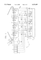
- FIG. 1 is a view schematically showing the structure of an ink delivery system for a liquid electrophotographic printer
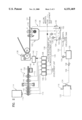
- FIG. 2 is a view schematically showing the structure of an ink delivery system for a liquid electrophotographic printer according to a preferred embodiment of the present invention.
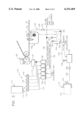
- FIG. 3 is a view schematically showing the structure of an ink delivery system for a liquid electrophotographic printer according to another preferred embodiment of the present invention.
- FIG. 1 shows a liquid electrophotographic color printer.
- a plurality of development units 14 is installed to develop an image corresponding to an electrostatic latent image formed on a photoreceptor medium 12 in the order of yellow, magenta, cyan, and black.
- a drying unit 16 is installed near the development unit 14 for black to dry the carrier remaining on the photoreceptor medium 12 after the development is completed.
- a plurality of circulation tanks 24, containing developer of a predetermined concentration and amount to be supplied to the development units 14, is provided.
- the carrier in the circulation tanks 24 includes the carrier collected from the drying unit 16.
- An ink delivery system 18 includes: ink cartridges 20 containing concentrated ink; a carrier cartridge 22 containing carrier; and the circulation tanks 24 connected to the ink cartridge 20, the carrier cartridge 22 and the development units 14, respectively.
- the ink delivery system 18 also includes a plurality of injection paths 28 for injecting the developer in the circulation tanks 24 into a development gap G between a development roller 26 of each of the development units 14 and the photoreceptor medium 12, and a waste tank 30 connected to the circulation tank 24 to collect waste developer from the circulation tank 24.
- the ink cartridges 20 and the carrier cartridge 22 are consumable parts which are replaced when the concentrated ink or carrier has been completely consumed.
- An agitator 21 for agitating the concentrated ink is installed in each ink cartridge 20.
- a circulation tank 24 is installed under each of the development units 14.
- the developer circulates between the circulation tank 24 and the development units 14 while being used for development unless the concentration and amount of the developer changes. Since the developer becomes contaminated as development continues, the waste developer in the circulation tank 24 is collected in the waste tank 30. Clean, new ink and carrier are supplied from the ink cartridges 20 and the carrier cartridge 22, respectively.
- a concentration sensor 32 and a level sensor 34 for detecting the concentration and level, respectively, ofthe developer contained in the circulation tanks 24 are installed in each circulation tank 24.
- the waste tank 30 is located under the circulation tanks 24 and is connected thereto by a plurality of waste developer collection paths 36.
- Valves 38 which are selectively opened or shut by a contamination sensor (not shown), are installed on each of the waste developer collection paths 36. When the valve 38 is open, the waste developer in the circulation tanks 24 moves under its own weight so as to be collected in the waste tank 30.
- the drying unit 16 includes a drying roller 40 for absorbing carrier remaining on the photoreceptor medium 12, a regeneration roller 42 rotating in contact with the drying roller 40 while heating the drying roller 40 so as to turn the carrier existing on the surface ofthe drying roller 40 into vapor, and a condenser 44 for condensing the carrier in a vapor state.
- the carrier condensed by the condenser 44 is temporarily stored in a condensation tank 46, and the carrier in the condensation tank 46 can be supplied to the circulation tanks 24.
- the cartridges 20 or 22 In the ink delivery system of the liquid electrophotographic printer having the above structure, when ink or carrier in any of the ink cartridges 20 or the carrier cartridge 22 is totally consumed, the cartridges 20 or 22 must be replaced with a new cartridge. In the ink cartridges 20, a functional part such as the agitator 21 is also replaced so that the cost of the ink cartridges 20 increases. Also, when the waste tank 30 is required to be replaced as the waste developer stored in the waste tank 30 increases, since the waste tank 30 is located under the circulation tanks 24, the development units 14 and the circulation tanks 24 must be disassembled prior to replacement. Thus, the job of replacing the waste tank 30 is inconvenient, and the main body of the printer may be contaminated by waste developer during replacement.
- an ink delivery system for a liquid electrophotographic printer includes: a circulation tank 104 containing developer which is supplied to a development unit 102 of the corresponding color; an ink tank 106 containing concentrated ink of a predetermined color supplied to the circulation tank 104; and a carrier tank 108 containing carrier which is supplied to the circulation tank 104.
- the ink tank 106 and the carrier tank 108 are provided with concentrated ink and carrier, respectively, from a refill cartridge 114 via an ink supply path 110 and a carrier supply path 112, respectively.
- the refill cartridge 114 can be installed at, and detached from, a refill cartridge installation unit 118 disposed on the upper portion of a main body 116 of the printer.
- the waste developer in the circulation tank 104 is collected in a waste tank 120. To drain the waste developer in the waste tank 120 into an empty waste refill cartridge 122, a waste refill cartridge installation unit 124 is installed at the outer surface of the main body 116.
- the above ink delivery system also includes an injection portion 126 for injecting developer from the circulation tank 104 into a development gap G of the development unit 102.
- a plurality of paths provides connections between the above-described development unit 102, the circulation tank 104, the ink tank 106, the carrier tank 108, the refill cartridge 114, and the waste tank 120.
- the circulation tank 104 is installed under the development unit 102. Developer is supplied to the development gap G via the injection portion 126, and the developer remaining in the development unit 102, after being used for development, is recollected in the circulation tank 104. Thus, the developer continuously circulates between the circulation tank 104 and the development unit 102 unless the concentration and amount of the developer changes.
- a concentration sensor 103 and a level sensor 105 for detecting the concentration and level, respectively, of the developer stored in the circulation tank 104 are installed at the circulation tank 104.
- the injection portion 126 comprises an injection path 128 through which developer passes, a pump 130 installed on the injection path 128 for pumping the developer, and a nozzle 132 installed at one end of the injection path 128 for injecting the developer into the development gap G.
- the ink tank 106 is fixedly installed in the main body 116 of the printer and is connected to the circulation tank 104 by a first supply path 134.
- the ink tank 106 can be provided with concentrated ink from the refill cartridge 114 through the ink supply path 110.
- An agitator 107 for agitating concentrated ink is installed in the ink tank 106.
- the carrier tank 108 is fixedly installed in the main body 116 of the printer, and is connected to the circulation tank 104 by a second supply path 136.
- the carrier tank 108 can be provided with carrier stored in the refill cartridge 114 through the carrier supply path 112.
- Valves 135 and 137 which are selectively opened and shut, are installed on the first and second supply paths 134 and 136, respectively.
- the valves 135 and 137 are opened, the concentrated ink and the carrier stored in the ink tank 106 and the carrier tank 108, respectively, are supplied to the corresponding circulation tank 104 due to movement under their own weight.
- the carrier dried and condensed by the drying unit 138 and collected in a condensation tank 140, can be supplied to the carrier tank 108 through a path 113 connected to the carrier supply path 112.
- the refill cartridge 114 is divided into a refill cartridge for ink, which refills the ink tank 106 with concentrated ink via the ink supply path 110, and a refill cartridge for carrier, which refills the carrier tank 108 with carrier via the carrier supply path 112.
- the refill cartridge for ink can be classified according to color such as yellow, magenta, cyan, and black.
- a cartridge/color identifying means (not shown) is used to discern the refill cartridge for ink from the refill cartridge for carrier, and identifying the color of the refill cartridge for ink.
- the cartridge/color identifying means is for identifying the type of refill cartridge 114 and connecting the refill cartridge 114 to the corresponding carrier supply path 112 or the ink supply path 110.
- the refill cartridge 114 is not provided with a functional part such as an agitator, and is installed at the refill cartridge installation unit 118 only when ink or carrier is supplied.
- the waste refill cartridge 122 emptied after being used, and used to supplement the ink or carrier, can be installed at the waste refill cartridge installation unit 124 to collect the waste developer.
- a single entrance 115 is provided at the refill cartridge 114.
- the entrance 115 functions as an outlet through which the concentrated ink or carrier is exhausted to the ink tank 106 or the carrier tank 108, respectively, when the refill cartridge 114 is installed at the refill cartridge installation unit 118.
- the entrance 115 also functions as an inlet through which the waste developer in the waste tank 120 enters when the refill cartridge 114 is installed at the waste refill installation unit 124.
- the refill cartridge installation unit 118 provides the concentrated ink or carrier in the installed refill cartridge 114 to the corresponding ink tank 106 or the carrier tank 108.
- the refill cartridge installation unit 118 includes a movable plate, such as rotary plate 146, in which ink inj ection holes 142 and a carrier injection hole 144 connected to the leading ends of the ink supply path 110 and the carrier supply path 112, respectively, are arranged at predetermined positions so as to be capable of rotating with respect to the main body 116 of the printer.
- a driving source 148 for rotating the rotary plate 146 is also provided in unit 118.
- the rotary plate 146 is installed so as to be capable of rotating around the center thereof, and has a geared portion at the outer circumferential surface thereof.
- the refill cartridge installation unit 118 can register the entrance 115 of the refill cartridge 114 with the ink injection hole 142 or the carrier injection hole 144, respectively, by rotation of the rotary plate 146.
- the waste tank 120 is provided for collecting waste developer when the developer circulating between the circulation tank 104 and the development unit 102 is contaminated.
- the waste tank 120 is connected to the circulation tank 104 by a waste developer collection path 152, on which there is installed a valve 154 which is selectively opened or shut by a contamination detection sensor (not shown). When the valve 154 is open, the waste developer in the circulation tank 104 is collected in the waste tank 120 by movement under its own weight.
- the waste refill cartridge installation unit 124 at which the empty waste refill cartridge 122 is installed, includes a waste developer exhaustion path 156 connected to the waste tank 120, and a waste developer exhaustion pump 158 installed on the waste developer exhaustion path 156 for exhausting the waste developer in the waste tank 120 to the waste refill cartridge 122.
- the developer in the circulation tank 104 is injected into the development gap G of the development unit 102 through the injection portion 126 in a developing mode.
- the injected developer is used for development of an electrostatic latent image area of a photoreceptor medium 101.
- the concentration sensor 103 and the level sensor 105 installed in the circulation tank 104 detect the concentration and amount, respectively, of the developer remaining in the circulation tank 104.
- the concentrated ink or carrier in the ink tank 106 or the carrier tank 108, respectively is supplied to the circulation tank 104 through the first supply path 134 or second supply path 136, respectively.
- the refill cartridge 114 When the ink tank 106 and the carrier tank 108 are emptied, and concentrated ink or carrier cannot be supplied to the circulation tank 104, the refill cartridge 114 is installed at the refill cartridge installation unit 118, and the entrance 115 of the refill cartridge 114 is connected to theink injection hole 142 or the carrier injection hole 144 of the rotary plate 146. Then, the ink or carrier in the refill cartridge 114 flows into the ink tank 106 or the carrier tank 108 through the ink supply path 110 or the carrier supply path 112, respectively. If the refill cartridge 114 is filled with compressed gas, the refill rate of the concentrated ink or carrier can be increased.
- the empty refill cartridge 122 is installed at the waste refill cartridge installation unit 124, and the waste developer exhaustion pump 158 is operated. As a result, waste developer in the waste tank 120 is collected in the empty waste refill cartridge 122 through the waste developer exhaustion path 156.
- FIG. 3 shows another preferred embodiment of the present invention in which a sliding plate 146', instead ofthe rotary plate 146, is adopted as the movable plate of the refill cartridge installation unit 118.
- the sliding plate 146' can be moved by a rack and pinion or a lead screw (not shown) with respect to the main body 116 of the printer.
- Ink injectionholes 142' and acarrierinjectionhole 144' are arrayed parallel to one another in the sliding plate 146' so that the entrance 115 of the refill cartridge 114 can selectively register with the ink injection hole 142' and the carrier injection hole 144' as the sliding plate 146' reciprocates.
- the same reference numerals as used in FIG. 2 are used to identify identical elements having the same functions as in FIG. 2, and accordingly the description thereof is omitted.
- the ink delivery system for a liquid electrophotographic printer has advantages as follows: first, since the ink tank and the carrier tank having functional parts are fixed inside the printer, the supply of ink and carrier is made easy by installing the refill cartridge at the refill cartridge installation unit provided at the main body of the printer to refill the ink or carrier; second, since the waste developer in the waste tank is collected in the empty waste refill cartridge, parts of the printer (such as the development unit) do not need to be disassembled to collect the waste developer, and the waste refill cartridge can be recycled; and third, manufacturing cost can be reduced by having functional parts, such as the agitator in the ink tank or the carrier tank, built into the main body of the printer, rather than in the refill cartridge.
Abstract
Description
Claims (15)
Applications Claiming Priority (2)
| Application Number | Priority Date | Filing Date | Title |
|---|---|---|---|
| KR1019990001248A KR100561448B1 (en) | 1999-01-18 | 1999-01-18 | Ink delivery system of wet electrographic printer |
| KR99-1248 | 1999-01-18 |
Publications (1)
| Publication Number | Publication Date |
|---|---|
| US6151469A true US6151469A (en) | 2000-11-21 |
Family
ID=19571566
Family Applications (1)
| Application Number | Title | Priority Date | Filing Date |
|---|---|---|---|
| US09/417,759 Expired - Lifetime US6151469A (en) | 1999-01-18 | 1999-10-14 | Ink delivery system for liquid electrophotographic printer |
Country Status (2)
| Country | Link |
|---|---|
| US (1) | US6151469A (en) |
| KR (1) | KR100561448B1 (en) |
Cited By (13)
| Publication number | Priority date | Publication date | Assignee | Title |
|---|---|---|---|---|
| US6411790B1 (en) * | 1999-08-16 | 2002-06-25 | Samsung Electronics Co., Ltd. | Apparatus for feeding developing solution for a wet type electrophotographic color printer |
| US20050002696A1 (en) * | 2002-10-31 | 2005-01-06 | Fordahl A. Kristine | Ink disposal in cartridges |
| KR100561448B1 (en) * | 1999-01-18 | 2006-03-16 | 삼성전자주식회사 | Ink delivery system of wet electrographic printer |
| US20070052771A1 (en) * | 2005-09-02 | 2007-03-08 | Canon Kabushiki Kaisha | Ink tank and recording apparatus using ink tank |
| US20070052768A1 (en) * | 2005-09-02 | 2007-03-08 | Canon Kabushiki Kaisha | Liquid Container |
| US20070052773A1 (en) * | 2005-09-02 | 2007-03-08 | Canon Kabushiki Kaisha | Liquid container |
| US20070098425A1 (en) * | 2005-10-28 | 2007-05-03 | Dror Kella | Methods for moderating variations in writing parameters in liquid toner printing |
| US20090123167A1 (en) * | 2007-11-14 | 2009-05-14 | Seiko Epson Corporation | Liquid Developer Collecting System and Image Forming Apparatus Including the Same |
| US20090220282A1 (en) * | 2008-02-29 | 2009-09-03 | Brother Kogyo Kabushiki Kaisha | Liquid Developer Cartridge and Image-Forming Device |
| US20140016954A1 (en) * | 2012-07-10 | 2014-01-16 | Konica Minolta, Inc. | Image forming apparatus |
| US20180024471A1 (en) * | 2016-07-21 | 2018-01-25 | Canon Kabushiki Kaisha | Image forming apparatus |
| WO2019059387A1 (en) * | 2017-09-19 | 2019-03-28 | キヤノン株式会社 | Image-forming apparatus |
| WO2019124195A1 (en) * | 2017-12-20 | 2019-06-27 | キヤノン株式会社 | Image forming device |
Citations (2)
| Publication number | Priority date | Publication date | Assignee | Title |
|---|---|---|---|---|
| US5933689A (en) * | 1998-02-27 | 1999-08-03 | Samsung Electronics Co., Ltd | Ink delivery system for liquid electrophotographic color printer including recycling capability for carrier |
| US6011943A (en) * | 1998-02-27 | 2000-01-04 | Samsung Electronics Co., Ltd. | Ink delivery system for liquid electrophotographic printer |
Family Cites Families (5)
| Publication number | Priority date | Publication date | Assignee | Title |
|---|---|---|---|---|
| US5442427A (en) * | 1993-10-04 | 1995-08-15 | Phoenix Precision Graphics, Inc. | Concentrate stirring for continuous printing |
| JPH09305029A (en) * | 1996-05-15 | 1997-11-28 | Ricoh Co Ltd | Wet type image-forming device |
| KR20000008442U (en) * | 1998-10-21 | 2000-05-15 | 윤종용 | Ink injection device for wet electrophotographic printer |
| KR100316658B1 (en) * | 1998-12-23 | 2002-04-17 | 윤종용 | Ink delivery system for wet electrophotographic printers |
| KR100561448B1 (en) * | 1999-01-18 | 2006-03-16 | 삼성전자주식회사 | Ink delivery system of wet electrographic printer |
-
1999
- 1999-01-18 KR KR1019990001248A patent/KR100561448B1/en not_active IP Right Cessation
- 1999-10-14 US US09/417,759 patent/US6151469A/en not_active Expired - Lifetime
Patent Citations (2)
| Publication number | Priority date | Publication date | Assignee | Title |
|---|---|---|---|---|
| US5933689A (en) * | 1998-02-27 | 1999-08-03 | Samsung Electronics Co., Ltd | Ink delivery system for liquid electrophotographic color printer including recycling capability for carrier |
| US6011943A (en) * | 1998-02-27 | 2000-01-04 | Samsung Electronics Co., Ltd. | Ink delivery system for liquid electrophotographic printer |
Cited By (26)
| Publication number | Priority date | Publication date | Assignee | Title |
|---|---|---|---|---|
| KR100561448B1 (en) * | 1999-01-18 | 2006-03-16 | 삼성전자주식회사 | Ink delivery system of wet electrographic printer |
| US6411790B1 (en) * | 1999-08-16 | 2002-06-25 | Samsung Electronics Co., Ltd. | Apparatus for feeding developing solution for a wet type electrophotographic color printer |
| US6999702B2 (en) | 2002-10-31 | 2006-02-14 | Samsung Electronics Co., Ltd. | Ink disposal in cartridges |
| US20050002696A1 (en) * | 2002-10-31 | 2005-01-06 | Fordahl A. Kristine | Ink disposal in cartridges |
| US6907213B2 (en) | 2002-10-31 | 2005-06-14 | Samsung Electronics Co., Ltd. | Ink disposal in cartridges |
| US20050002697A1 (en) * | 2002-10-31 | 2005-01-06 | Fordahl A. Kristine | Ink disposal in cartridges |
| US7197266B2 (en) | 2002-10-31 | 2007-03-27 | Samsung Electronics Co, Ltd | Ink disposal in cartridges |
| US20070052768A1 (en) * | 2005-09-02 | 2007-03-08 | Canon Kabushiki Kaisha | Liquid Container |
| US20070052773A1 (en) * | 2005-09-02 | 2007-03-08 | Canon Kabushiki Kaisha | Liquid container |
| US20070052771A1 (en) * | 2005-09-02 | 2007-03-08 | Canon Kabushiki Kaisha | Ink tank and recording apparatus using ink tank |
| US7618136B2 (en) * | 2005-09-02 | 2009-11-17 | Canon Kabushiki Kaisha | Ink tank and recording apparatus using ink tank |
| US7621627B2 (en) * | 2005-09-02 | 2009-11-24 | Canon Kabushiki Kaisha | Liquid container |
| US7708394B2 (en) * | 2005-09-02 | 2010-05-04 | Canon Kabushiki Kaisha | Liquid container |
| US20070098425A1 (en) * | 2005-10-28 | 2007-05-03 | Dror Kella | Methods for moderating variations in writing parameters in liquid toner printing |
| US7668472B2 (en) * | 2005-10-28 | 2010-02-23 | Hewlett-Packard Development Company, L.P. | Methods for moderating variations in writing parameters in liquid toner printing |
| US20090123167A1 (en) * | 2007-11-14 | 2009-05-14 | Seiko Epson Corporation | Liquid Developer Collecting System and Image Forming Apparatus Including the Same |
| US8005384B2 (en) * | 2007-11-14 | 2011-08-23 | Seiko Epson Corporation | Liquid developer collecting system and image forming apparatus including the same |
| US20090220282A1 (en) * | 2008-02-29 | 2009-09-03 | Brother Kogyo Kabushiki Kaisha | Liquid Developer Cartridge and Image-Forming Device |
| US8270880B2 (en) * | 2008-02-29 | 2012-09-18 | Brother Kogyo Kabushiki Kaisha | Liquid developer cartridge and image-forming device |
| US20140016954A1 (en) * | 2012-07-10 | 2014-01-16 | Konica Minolta, Inc. | Image forming apparatus |
| US8897680B2 (en) * | 2012-07-10 | 2014-11-25 | Konica Minolta, Inc. | Image forming apparatus |
| US20180024471A1 (en) * | 2016-07-21 | 2018-01-25 | Canon Kabushiki Kaisha | Image forming apparatus |
| US10139756B2 (en) * | 2016-07-21 | 2018-11-27 | Canon Kabushiki Kaisha | Image forming apparatus |
| WO2019059387A1 (en) * | 2017-09-19 | 2019-03-28 | キヤノン株式会社 | Image-forming apparatus |
| WO2019124195A1 (en) * | 2017-12-20 | 2019-06-27 | キヤノン株式会社 | Image forming device |
| US10908537B2 (en) | 2017-12-20 | 2021-02-02 | Canon Kabushiki Kaisha | Image forming apparatus |
Also Published As
| Publication number | Publication date |
|---|---|
| KR100561448B1 (en) | 2006-03-16 |
| KR20000051016A (en) | 2000-08-16 |
Similar Documents
| Publication | Publication Date | Title |
|---|---|---|
| US6151469A (en) | Ink delivery system for liquid electrophotographic printer | |
| KR100311007B1 (en) | Ink delivery system for liquid electro-photographic color printer | |
| KR100311006B1 (en) | Ink delivery system for liquid electro-photographic printer | |
| US8422915B2 (en) | Developer cartridge, developing device, and image forming apparatus having the same | |
| KR100497343B1 (en) | Ink delivery system for liquid electro-photographic color printer | |
| JP6731183B2 (en) | Developer supply device and image forming apparatus | |
| JP4547179B2 (en) | Image forming apparatus and agent storage container used for the image forming apparatus | |
| KR100253143B1 (en) | Developer supplying apparatus of wet electrographic printer &tank/cartridge assembly | |
| KR100594831B1 (en) | Image formation apparatus and developer collection vessel used therewith | |
| KR100316658B1 (en) | Ink delivery system for wet electrophotographic printers | |
| US6434353B1 (en) | Ink feeding valve of a wet type electrophotographic printer | |
| KR100343160B1 (en) | Ink delivery system for wet electrophotographic printers | |
| KR100333817B1 (en) | Apparstus for delivering developer of a liquid electrophotographic color printer | |
| KR20000008442U (en) | Ink injection device for wet electrophotographic printer | |
| KR100338739B1 (en) | Ink refill cartridge able to withraw exhausted ink of wet electrographic printer | |
| KR100341322B1 (en) | Ink cartridge for liquid electrophotographic color printer | |
| KR100385050B1 (en) | Ink delivery system for liquid color printer | |
| US20040005173A1 (en) | Liquid electrophotographic image forming apparatus | |
| KR100513707B1 (en) | Ink cartridge for liquid electrophotographic printer | |
| KR100316661B1 (en) | Waste tank and wet device for wet electrophotographic printing press | |
| KR20010064302A (en) | Ink cartridge for liquid electrophotographic printer | |
| KR20000012396U (en) | Ink delivery system for wet electrophotographic printers | |
| KR100331319B1 (en) | Apparatus for prohibiting settlement of toner of printer | |
| US7164879B2 (en) | Reversible ink cartridge | |
| KR100416540B1 (en) | Ink supply apparatus for wet type printer |
Legal Events
| Date | Code | Title | Description |
|---|---|---|---|
| AS | Assignment |
Owner name: SAMSUNG ELECTRONICS CO., LTD., A CORP. ORGANIZED U Free format text: ASSIGNMENT OF ASSIGNORS INTEREST;ASSIGNOR:LEE, HYONG-GU;REEL/FRAME:010562/0867 Effective date: 20000201 |
|
| STCF | Information on status: patent grant |
Free format text: PATENTED CASE |
|
| FPAY | Fee payment |
Year of fee payment: 4 |
|
| FPAY | Fee payment |
Year of fee payment: 8 |
|
| FEPP | Fee payment procedure |
Free format text: PAYOR NUMBER ASSIGNED (ORIGINAL EVENT CODE: ASPN); ENTITY STATUS OF PATENT OWNER: LARGE ENTITY |
|
| FPAY | Fee payment |
Year of fee payment: 12 |
|
| AS | Assignment |
Owner name: S-PRINTING SOLUTION CO., LTD., KOREA, REPUBLIC OF Free format text: ASSIGNMENT OF ASSIGNORS INTEREST;ASSIGNOR:SAMSUNG ELECTRONICS CO., LTD;REEL/FRAME:041852/0125 Effective date: 20161104 |
|
| AS | Assignment |
Owner name: HP PRINTING KOREA CO., LTD., KOREA, REPUBLIC OF Free format text: CHANGE OF NAME;ASSIGNOR:S-PRINTING SOLUTION CO., LTD.;REEL/FRAME:047370/0405 Effective date: 20180316 |
|
| AS | Assignment |
Owner name: HP PRINTING KOREA CO., LTD., KOREA, REPUBLIC OF Free format text: CORRECTIVE ASSIGNMENT TO CORRECT THE DOCUMENTATION EVIDENCING THE CHANGE OF NAME PREVIOUSLY RECORDED ON REEL 047370 FRAME 0405. ASSIGNOR(S) HEREBY CONFIRMS THE CHANGE OF NAME;ASSIGNOR:S-PRINTING SOLUTION CO., LTD.;REEL/FRAME:047769/0001 Effective date: 20180316 |
|
| AS | Assignment |
Owner name: HP PRINTING KOREA CO., LTD., KOREA, REPUBLIC OF Free format text: CHANGE OF LEGAL ENTITY EFFECTIVE AUG. 31, 2018;ASSIGNOR:HP PRINTING KOREA CO., LTD.;REEL/FRAME:050938/0139 Effective date: 20190611 |
|
| AS | Assignment |
Owner name: HEWLETT-PACKARD DEVELOPMENT COMPANY, L.P., TEXAS Free format text: CONFIRMATORY ASSIGNMENT EFFECTIVE NOVEMBER 1, 2018;ASSIGNOR:HP PRINTING KOREA CO., LTD.;REEL/FRAME:050747/0080 Effective date: 20190826 |