US6151384A - X-ray tube with magnetic electron steering - Google Patents
X-ray tube with magnetic electron steering Download PDFInfo
- Publication number
- US6151384A US6151384A US09/115,322 US11532298A US6151384A US 6151384 A US6151384 A US 6151384A US 11532298 A US11532298 A US 11532298A US 6151384 A US6151384 A US 6151384A
- Authority
- US
- United States
- Prior art keywords
- anode
- cathode
- electrons
- magnetic field
- ray tube
- Prior art date
- Legal status (The legal status is an assumption and is not a legal conclusion. Google has not performed a legal analysis and makes no representation as to the accuracy of the status listed.)
- Expired - Lifetime
Links
Images


Classifications
-
- H—ELECTRICITY
- H01—ELECTRIC ELEMENTS
- H01J—ELECTRIC DISCHARGE TUBES OR DISCHARGE LAMPS
- H01J35/00—X-ray tubes
- H01J35/02—Details
- H01J35/14—Arrangements for concentrating, focusing, or directing the cathode ray
- H01J35/153—Spot position control
Definitions
- This invention relates to the field of X-ray tubes, specifically tubes wherein a magnetic field urges electrons toward the anode.
- X-ray sources have many applications. For example, hundred kilovolt X-ray tubes can be used in agriculture for de-infestation of fruits, vegetables, grains, and lumber. They can also be used to sterilize food for storage without refrigeration, and to destroy pathogenic microorganisms in meat, seafood, and poultry. They can also be used for non-destructive testing and inspection of industrial tools and systems (e.g., airplanes) and for water purification.
- industrial tools and systems e.g., airplanes
- X-ray tubes consist of an electron source and an accelerating potential that impinges a beam of electrons onto an X-ray conversion target anode.
- the anode is typically made of a high atomic number material so that it efficiently decelerates the electrons that penetrate into it, thus generating Bremsstrahlung X-radiation.
- Many production processing applications require electron beams of only a few hundred kilovolts accelerating potential, so the X-ray pattern is substantially isotropic.
- One common X-ray tube design involves a diode, wherein a heated cathode provides electrons and an applied voltage between the cathode and an anode accelerates the electrons onto the anode.
- Field shaping electrodes around the cathode can be used the create an accelerating electric field that will focus the electron beam onto the anode.
- a large part of the energy in the electrons can be converted into heat in the anode; some of the energy is carried away by electrons that miss or bounce off the target; the remaining small portion is converted into subsequently reflected from anode A1, they will carry away energy that might otherwise have further contributed to X-ray production.
- Radiation along directions other than through the window W1 can be absorbed by cathode C1, anode A1, and envelope E1, contributing to undesirable heating of tube T1 rather than to useful radiation of the target TG1.
- the present invention provides an X-ray tube that uses magnetic steering of electrons to increase the tube's efficiency and reduce the external cooling required.
- the present invention provides a cathode and anode mounted with an evacuated envelope.
- a magnetic field generator imposes a magnetic field that urges electrons toward the anode, reducing the number of electrons that would otherwise escape the anode and cause electron heating of the tube.
- the magnetic field also urges electrons toward the portions of the anode that will produce X-rays that are not shadowed by the cathode, improving the useable X-ray pattern.
- FIG. 1 is a schematic view of a conventional X-ray tube.
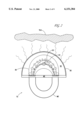
- FIG. 2 is a schematic view of an X-ray tube according to the present invention.
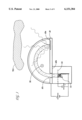
- FIG. 3 is a schematic view of an X-ray tube according to the present invention.
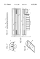
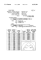
- FIGS. 4(a,4b,4c,4d) is a schematic view of an example design according to the present invention.
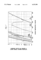
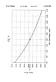
- FIG. 5 is a chart of current variation versus filament temperature corresponding to the example design.
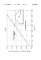
- FIG. 6 is an exposition of Larmor radius corresponding to the example design.
- FIG. 7 is a chart of Kilpatrick breakdown criterion corresponding to the example design.
- FIG. 8 is a chart of electric stress on a cathode due to a flat anode corresponding to the example design.
- FIG. 9 is a chart of electric stress on a cathode due to an outer shield/filter corresponding to the example design.
- the present invention provides an X-ray tube that uses magnetic steering of electrons to increase the tube's X-ray production efficiency and reduce cooling required to cool the X-ray tube.
- FIG. 2 shows a schematic view of an X-ray tube T2 according to the present invention.
- Envelope E2 defines an evacuated interior volume V2.
- Cathode C2 mounts with envelope E2 so that at least a portion of cathode C2 is in communication with interior volume V2.
- Anode A2 mounts with envelope E2 so that at least a portion of anode A2 is in communication with interior volume V2.
- Magnetic field generator M2 mounts with envelope E2.
- Grid G2 mounts with envelope E2 and can modulates the quantity and initial trajectories of electrons from cathode C2.
- a narrow cathode C2 and grid G2 structure such as shown in FIG. 2 can minimize shadowing of generated X-rays.
- the electric field lines from a narrow cathode C2 and grid G2 structure are divergent, however, making it more likely that electrons from cathode C2 and grid G2 structure will not hit the anode A2 and generate X-rays, but rather strike other structures and generate only heat.
- Grid G2 surrounds cathode C2 and moderates the flow of electrons from cathode C2. This in turn controls the impedance of the electron gun (cathode, grid, and anode) and power output of the tube T2. If a grid were not provided, the impedance of the electron gun would be very low (space charge limited flow) and it would be difficult to limit the power output of the X-Ray tube to the desired level. Furthermore, an unnecessarily large power input to the tube T2 would be needed to keep the voltage up between the anode A2 and cathode C2. It is desirable to generate only the required amount of X-Ray power to the target TG2 and in turn supply no more than the minimum amount of power to the tube T2 needed to generate this required X-Ray output.
- Grid G2 can discourage electrons from leaving cathode C2 on paths directly to anode A2, reducing the production of X-rays that would be shadowed by cathode C2.
- Grid G2 can also discourage electrons from leaving cathode C2 on paths that are substantially away from anode A2, reducing electron heating of envelope E2 by electrons on paths that intersect envelope E2 before they intersect anode A2.
- cathode C2 In operation, cathode C2 emits electrons. Electrons from cathode C2 have initial velocity vectors away from cathode C2, substantially conformed to magnetic field lines B2. For electrons to contribute to X-ray production they must reach anode A2. Magnetic field generator M2 generates a magnetic field represented by magnetic field lines B2.
- F is the force vector on the electron due to the combined electric and magnetic fields
- e is the charge of an electron
- E is the local electric field due to the voltage applied between cathode C2 and anode A2
- ⁇ is the electron velocity vector
- x denotes vector cross product
- B and is the local applied magnetic flux density vector.
- the Lorentz forces cause the electrons to spiral around the direction of the applied magnetic field and constrain their net motion to be along the magnetic field. Electrons can thus be prevented from impacting other parts of tube T2 Electrons scattered from anode A2 spiral along the magnetic field lines and are directed back toward anode A2 so that a higher percentage of electrons will contribute to X-ray production.
- Electrons on trajectories that terminate at anode A2 are do not require urging by magnetic field B2. Such electrons, unless scattered from anode A2, contribute to X-ray production, and do not cause electron heating of any part of the tube other than anode A2.
- Scattered electrons impact anode A2 and are reflected therefrom. Electron scattering from anode A2 reduces the efficiency of X-ray production. Such scattered electrons are urged by magnetic field B2 back to anode A2. If such scattered electrons were not affected by magnetic field B2, they could impact envelope E2 and contribute to electron heating thereof rather than to X-ray production. Steering of scattered electrons by magnetic field B2 accordingly increases X-ray production efficiency and reduces electron heating of envelope E2.
- Electrons on initial trajectories that do not terminate at anode A2 are also urged toward anode A2 by magnetic field B2.
- Magnetic field B2 urges such electrons along paths spiraling around magnetic field lines B2, intersecting anode A2. If such electrons were not affected by magnetic field B2, they would impact envelope E2 and contribute to electron heating thereof rather than to X-ray generation. Consequently, steering of such electrons by magnetic field B2 reduces electron heating of envelope E2 and increases the efficiency of X-ray production.
- FIG. 3 Another embodiment of the present invention is shown in FIG. 3.
- a grid G3 and cathode C3 are placed behind an anode A3, where the front face A3a of anode A3 is designated as the side from which X-radiation is emitted.
- Electrons are accelerated by an accelerating potential from the grid G3 and cathode C3 toward the back face A3b of anode A3.
- they reach anode A3 they pass through an opening A3c in anode A3 and enter a magnetic field B3 on the front side of anode A3 that is directed transverse to the direction in which the electrons are moving.
- Magnetic field B3 produces a Lorentz force on the electrons that curves their trajectories back onto the front face A3a of anode A3.
- X-rays are generated where the electrons strike anode A3 and are radiated in the forward direction away from the front face A3a of anode A3.
- the embodiment illustrated in FIG. 3 has several differences with respect to the embodiment illustrated in FIG. 2. For example, it may be possible to use a weaker applied magnetic field to bend the electron trajectories back onto the anode in the embodiment of FIG. 3, depending upon the allowable radius of curvature of the electron trajectories in front of the anode. Also, in the embodiment of FIG. 3, there is no shadowing of the X-rays generated in the useful forward direction by the grid and cathode structure (since the grid and cathode are behind the anode).
- FIG. 3 separates the region where the trajectory of the electrons is bent by the applied magnetic field and the region where the electric field accelerates them.
- the spacing between the anode and cathode must be large enough to prevent uncontrolled electron flow between the cathode and anode. This limitation also applies to the spacing that can be tolerated between the vacuum envelope and the grid/cathode structure. If the grid/cathode is on the front side of the anode, as in the embodiment illustrated in FIG. 2, the minimum anode-cathode and cathode-envelope spacings impose a bound upon how close the product that is being irradiated can be placed to the source of X-rays.
- the bend radius of the electron beam on the front side of the anode determines how close the vacuum envelope can be to the source of X-rays at the anode without the electrons striking the vacuum envelope.
- the bend radius can be made as small as desired by controlling the applied magnetic field.
- scattered electrons can impact the envelope since the magnetic field does not return reflected electrons to the anode so that they can further contribute to X-ray production.
- Thermionic cathodes can be made from materials that are specially treated so that they readily emit electrons in plentiful quantities when heated to temperatures below the melting points of the cathode material.
- Materials suitable for use in thermionic cathodes include oxide coatings, nickel, impregnated nickel, impregnated tungsten, plain tungsten and thoriated tungsten.
- Thoriated tungsten is one of the most common and useful of the thermionic cathode materials because it exhibits a generous electron emission current density (4 Amperes/cm 2 ) when heated to about 2000° Kelvin, that is relatively independent of the exact temperature over a range of about 100° Kelvin.
- the anode can comprise two portions: an X-ray converter portion, and a supporting substrate.
- Anode materials should have minimal out-gassing properties to minimize the gas generated by the thermal and radiation fluxes.
- a coating or layer of high atomic number material on the anode can comprise an X-ray converter portion. It preferably is of a thickness at least equivalent to the penetration depth range of electrons with the energy of the anode-cathode accelerating potential. At the lower accelerating potentials that are required by many applications, the conversion of electron energy into X-rays is only a few percent efficient. Since the electron energy that doesn't go into the production of X-Rays mostly goes into the heating of the anode, the anode of a high power continuously operating X-Ray tube must sustain a tremendous heat flux. Furthermore, production efficiency of X-Rays by the anode is a function of both the mass density and atomic number of the anode material.
- the anode substrate that the X-ray converter layer is on should be sufficiently thick to allow the removal of the heat generated in the X-ray conversion layer.
- the anode substrate that supports the X-ray conversion layer can be made of a suitable magnetic material and shape so as to shape the magnetic field which guides the electrons onto the X-ray converter portion of the anode.
- the envelope material preferably has minimal out-gassing properties to minimize the gas generated by the thermal and radiation fluxes.
- the envelope material preferably is a good thermal conductor so that it will help carry away the heat generated by the X-radiation that hits it.
- the envelope material preferably is tolerant of continual bombardment by X-radiation.
- the envelope material preferably absorbs as little of the generated X-rays as possible, making it preferable to choose a material that has a low atomic number, a low mass density and sufficient strength so that thin sections can serve as a vacuum vessel. Titanium is one of the most commonly used window or envelope materials because it is relatively inexpensive and it is sufficiently strong that it can be made extremely thin, compensating for higher density and atomic number compared with other envelope materials.
- a supporting structure like the supporting framework in a tent--called a "hibachi"
- aluminum is a commonly used window material due to its low cost, low atomic number and low density.
- a recommended electron and X-Ray window material is beryllium. It has an atomic number of only 4, a very low mass density, high tensile strength, a high melting point and a high thermal conductivity. All of these properties are desirable in an X-Ray envelope window. Beryllium, however, is expensive, hard to obtain in large sheets, and forms a toxic oxide.
- a window portion of an envelope can be made of multiple layers of different metals to act as a deliberate filter for the X-ray spectrum that emerges from it.
- the magnetic field generator can comprise a permanent magnet or a combination of a permanent and electro-magnet with a suitable pole-piece configuration to achieve the required guiding magnetic field around and between the anode and cathode structures.
- a suitable magnet can be made using a material such as Alnico, carbon steel, chromium steel, cobalt steel, Cunico, Cunife, Ferroxdur, Silmanol, Vicalloy, Alni, Oerstit, Comol, Remalloy, platinum-cobalt, tungsten-steel, Alcomax, and combinations thereof.
- An accelerating potential of 10 Kilovolts to several 100 Kilovolts is suitable.
- the accelerating potential used depends upon the application. Higher potentials yield greater X-ray penetration and a narrower beam of X-rays.
- the accelerating potential can be selected upon the basis of required X-ray energy and spectrum to achieve optimal penetration of the target product.
- the acceleration potential can depend upon product thickness, density, X-ray absorption characteristics, X-ray attenuation properties, and treatment uniformity requirements.
- the acceleration potential can also depend upon whether the product is being irradiated from only one side or from two or more sides.
- Magnetic field strength of 0.001 Tesla to 0.1 Tesla is suitable.
- the applied magnetic field along with the potential through which the electron has been accelerated at each point along its trajectory determines the radius with which it spirals around the magnetic field line that it is "on". This radius is called the Larmor radius and is given by equation 2.
- Equation 2 m is the mass of the electron, e is the electronic charge, ⁇ is the magnitude of the electron velocity in the plane perpendicular to B, and B is the magnitude of the magnetic flux density at the point of interest.
- Intermittent to continuous operation are appropriate. Some applications require intermittent duty and some require continuous duty. For example, in an assembly line food processing application where separate crates are moving along a conveyer, the X-ray beam can be turned off between crates. On the other hand, if produce lying loose on a conveyer is being treated, the X-ray machine can be operated continuously.
- the grid can be cooled with radiative cooling or forced convection cooling.
- the window can be cooled with natural convection cooling.
- the anode can be cooled with forced water convection through a cooling manifold.
- the cooling regime used depends upon the allowable temperature of the structure being cooled and the amount of heat power being removed.
- the anode is absorbing most of the electron energy and is generating the most heating power. Since the vacuum seal and outside world (including human operators) is exposed to the potentially extremely high temperature of the anode, it is desirable to keep the anode cool. Therefore, the anode can use a more aggressive cooling scheme such a forced liquid convection.
- the grid is the second most heated component since it surrounds the thermionic cathode and is relatively isolated in the vacuum. If the grid is made of a high temperature material, however, there is no reason that it cannot be allowed to run hot, allowing the possibility of natural radiative cooling.
- the X-ray window can be made so that it allows most of the X-ray energy to pass through it. Therefore, it should receive a minimum of heating, allowing it to be cooled by the natural convection of the air around it.
- FIGS. 4(a,b,c,d) shows an example design according to the present invention.
- the device generates X-rays in the forward direction for commercial processing applications.
- the forward direction is defined as the side of the tungsten anode G that the elections strike in order to generate X-rays.
- the cathode/grid assembly is made very narrow so that it doesn't obstruct the generated X-rays.
- the electrons are focused onto the desired anode regions by an applied magnetic field in spite of the divergent electric field.
- the thoriated tungsten cathode filament N housed in the control grid F can be resistively heated by passing an electrical current through it via the electrical feed-throughs D, E.
- the cathode filament is supported inside the anode tube by ceramic disks O.
- the thoriated tungsten cathode filament is heated to about 2050° Kelvin, it will emit about 3.5 Amperes of electrons per square centimeter of cathode surface area.
- the current flux in this cloud of electrons is essentially independent of temperature provided the temperature swings are less than ⁇ 50° Kelvin around the nominal temperature of 2050° Kelvin.
- a 1 corresponds to oxide coated, puled current heated, A 2 to oxide coated, direct current heated, B to pressed nickel, C to impregnated nickel, D to pressed and impregnated tungsten, E to thoriated tungsten, and F to a tungsten filament.
- An accelerating potential is applied to the cathode relative to the anode via the feed-throughs D, E and a small retarding electrical potential relative to the cathode is applied to the control grid via the electrical feed through B.
- the region between the cathode and control grid is operating in the space charge limited flow regime.
- the potential between the cathode and grid that is necessary to cause the current that is desired for this particular design to flow from the cathode to the grid and out the grid slit, J, is about 87 volts.
- a triode power of 150 kW corresponds to a grid voltage of 87V; a triode power of 6 kW corresponds to a grid voltage of 10V.
- the electrons that are emitted through the slits in the grid tube are accelerated by the electrical potential between the cathode and anode G. Without a magnetic field these electrons tend to follow the electric field lines of force set up by the potential between the cathode and anode.
- the grid should be small in diameter so that it doesn't obstruct the X-rays that are radiated toward it from the anode. Since the grid tube is small in-diameter compared to the spacing between the grid and the anode, the electric lines of force that the electrons will follow in the absence of an applied magnetic field are very divergent. Without an applied magnetic field the electrons will strike all over the inside of X-ray window I in addition to all over the back plate G.
- FIG. 6 shows that an applied magnetic field of 1.4 Gauss is required in order to make the electrons from the anode slit hit a 20 mm wide anode target zone when the electrons leaving the anode slit are heated to 2050° Kelvin. Horseshoe magnets A apply the required magnetic field.
- FIG. 7 gives the Kilpatrick breakdown criterion for conditioned electrodes. The curve is based upon empirical data using many different electrode materials, spacings, and electrical potentials. The initiation of electrical breakdown is considered to be due to both field emission and energetic ions striking grid F.
- the Kilpatrick criterion is a function of both the maximum energy W in FIG. 7 that an energetic ion striking the grid might have and the electric stress E c in FIG. 7 at the grid surface.
- the electrical potential applied between grid F and the anode is 300 kV. According to FIG.
- Equation 4 gives the general formulation for the electrical stress on the grid, where V is the applied voltage, x is the separation distance, and r is the radius of the grid cylinder. ##EQU3##
- FIG. 8 gives the results of using this formulation to determine the value of the ratio of the distance of the grid from the anode to the radius of the grid that yields an electrical stress of 67 kV/cm on the grid.
- the minimum allowable value of this ratio is 4, so if the grid is 5 cm in diameter then it must be more than 10 cm away from the anode to prevent direct electrical breakdown.
- FIG. 9 shows the same calculation to prevent direct electrical breakdown from the grid to the X-ray window, which is made of titanium and is at the same electrical potential as the anode.
- An X-ray window radius of 9 inches is highlighted in FIG. 9 because it yields an electrical stress on the grid of 57 kV/cm, safely below the maximum allowable value of 67 kV/cm. In the example design we chose to be even more conservative and used an X-ray window radius of 11.5 inches.
- the inside of the X-ray head must be evacuated, so that there are very few molecules to interfere with the acceleration of the electrons from the grid slits to the anode.
- a vacuum pump is attached at port C in FIG. 4d in order to draw this vacuum.
- the front face of the vacuum envelope I where the X-rays emerge must be thin and made of a low density, low atomic number material such as titanium.
- This thin X-ray window material is prevented from collapsing inwardly under the vacuum by rigid ribs K that hold it up much like tent poles hold up a tent's fabric.
- These ribs are arched for mechanical strength and are made of a mechanically strong material such as stainless steel.
- the cathode heats the grid tube so it must be allowed to either radiatively cool or it must be actively cooled by flowing coolant through it via feed-throughs D, E.
- Radiative grid cooling characteristics can be determined as shown in equation 5.
- T is the grid temperature
- T 0 is the surrounding temperature
- ⁇ t is the emissivity
- ⁇ is the Stefan-Boltzmann constant.
- the resulting grid temperature is 830° K. and the resulting filament power is 422 Watts.
- Convective grid cooling characteristics can be determined as shown in equation 6.
- Equation 6 Q A is the air flow [ft 3 /min]
- T out is the air outlet temperature
- T in is the air inlet temperature.
- the resulting grid temperature is 310° K.
- the resulting filament power is 434 Watts
- the resulting air flow is 77 ft 3 /min.
- the grid could be made of 304 stainless steel. This steel has a melting point of 1783° Kelvin, which is well above the maximum temperature of 830° Kelvin given in equation 5 that it would reach if it were radiatively cooled.
- the choice of the grid material also must take into consideration electron emission from the grid itself at the operating temperature This emission must be small compared to the main electron current that emerges from the grid slits.
- Q w [GPM] is the water flow rate
- P.sub.[Watts] is the cooling power (150 kW)
- ⁇ T water [° C.] is the temperature rise in water (55° C.).
- the resulting water flow rate is 10.4 GPM.
- Equation 8 Q A is the air flow [ft 3 /min]
- T out is the air outlet temperature (355° K.)
- T in is the air inlet temperature (300° K.).
- the resulting air flow rate is 193 ft 3 /min.
- the anode target area G is made of a high density, high atomic number material This material can be expensive and difficult to machine. Only a relatively thin layer of X-ray conversion material is required in the target area on the anode because it stops the electrons in a very short distance. This thin conversion layer can be intimately attached to anode plate M so that there is good thermal conduction into the anode cooling manifold.
- the example design used flame sprayed tungsten for the converter material and 304 stainless steel for the anode plate and cooling manifold.
Abstract
Description
R.sub.L =(mν)/(eB) equation 2
Power.sub.[Watt/cm.spsb.2.sub.] =ε.sub.t σ(T.sup.4 -T.sub.0.sup.4)[Watts/cm.sup.2 ] equation 5
Power.sub.[Watts/cm.spsb.2.sub.] =169Q.sub.A (T.sub.out /T.sub.in -1)[Watts/cm.sup.2 ] equation 6
Claims (14)
Priority Applications (1)
| Application Number | Priority Date | Filing Date | Title |
|---|---|---|---|
| US09/115,322 US6151384A (en) | 1998-07-14 | 1998-07-14 | X-ray tube with magnetic electron steering |
Applications Claiming Priority (1)
| Application Number | Priority Date | Filing Date | Title |
|---|---|---|---|
| US09/115,322 US6151384A (en) | 1998-07-14 | 1998-07-14 | X-ray tube with magnetic electron steering |
Publications (1)
| Publication Number | Publication Date |
|---|---|
| US6151384A true US6151384A (en) | 2000-11-21 |
Family
ID=22360627
Family Applications (1)
| Application Number | Title | Priority Date | Filing Date |
|---|---|---|---|
| US09/115,322 Expired - Lifetime US6151384A (en) | 1998-07-14 | 1998-07-14 | X-ray tube with magnetic electron steering |
Country Status (1)
| Country | Link |
|---|---|
| US (1) | US6151384A (en) |
Cited By (9)
| Publication number | Priority date | Publication date | Assignee | Title |
|---|---|---|---|---|
| US20010017353A1 (en) * | 2000-02-25 | 2001-08-30 | Nissin Electric Co., Ltd. | Ion source and operation method thereof |
| US20030123612A1 (en) * | 2000-03-30 | 2003-07-03 | Pelc Norbert J. | X-ray tube for operating in a magnetic field |
| WO2005069341A2 (en) * | 2004-01-13 | 2005-07-28 | Koninklijke Philips Electronics, N.V. | Composite frame for x-ray tubes |
| US6975895B1 (en) | 2000-03-30 | 2005-12-13 | The Board Of Trustees Of The Leland Stanford Junior University | Modified X-ray tube for use in the presence of magnetic fields |
| US6976953B1 (en) | 2000-03-30 | 2005-12-20 | The Board Of Trustees Of The Leland Stanford Junior University | Maintaining the alignment of electric and magnetic fields in an x-ray tube operated in a magnetic field |
| WO2013032019A1 (en) * | 2011-08-31 | 2013-03-07 | Canon Kabushiki Kaisha | X-ray generator and x-ray imaging apparatus |
| US20130182825A1 (en) * | 2012-01-18 | 2013-07-18 | Varian Medical Systems, Inc. | X-ray tube cathode with magnetic electron beam steering |
| US9570264B2 (en) | 2011-08-31 | 2017-02-14 | Canon Kabushiki Kaisha | X-ray generator and X-ray imaging apparatus |
| JP2017208355A (en) * | 2012-06-05 | 2017-11-24 | モックステック・インコーポレーテッド | Amorphous carbon and aluminum x-ray window |
Citations (16)
| Publication number | Priority date | Publication date | Assignee | Title |
|---|---|---|---|---|
| US4007375A (en) * | 1975-07-14 | 1977-02-08 | Albert Richard D | Multi-target X-ray source |
| US4104526A (en) * | 1973-04-24 | 1978-08-01 | Albert Richard D | Grid-cathode controlled X-ray tube |
| US4359660A (en) * | 1980-12-15 | 1982-11-16 | Physics International Company | Series diode X-ray source |
| US4652763A (en) * | 1985-03-29 | 1987-03-24 | Energy Sciences, Inc. | Electron-beam irradiation sterilization process |
| US4694457A (en) * | 1982-07-20 | 1987-09-15 | Unisearch Limited | Methods of steering and focusing ion and electron beams |
| US4764947A (en) * | 1985-12-04 | 1988-08-16 | The Machlett Laboratories, Incorporated | Cathode focusing arrangement |
| US4912738A (en) * | 1988-02-08 | 1990-03-27 | R & D Associates | Magnetically energized pulser |
| US5048068A (en) * | 1989-11-16 | 1991-09-10 | Turchi Peter J | Magnetically operated pulser |
| US5090041A (en) * | 1990-09-20 | 1992-02-18 | Picker International, Inc. | X-ray tube anode speed reducer |
| US5105456A (en) * | 1988-11-23 | 1992-04-14 | Imatron, Inc. | High duty-cycle x-ray tube |
| US5268955A (en) * | 1992-01-06 | 1993-12-07 | Picker International, Inc. | Ring tube x-ray source |
| US5422926A (en) * | 1990-09-05 | 1995-06-06 | Photoelectron Corporation | X-ray source with shaped radiation pattern |
| US5426686A (en) * | 1989-03-22 | 1995-06-20 | Rentzepis; Peter M. | Compact high-intensity pulsed x-ray source, particularly for lithography |
| US5563407A (en) * | 1993-09-20 | 1996-10-08 | Kabushiki Kaisha Toshiba | X-ray image intensifier tube with an ion pump to maintain a high vacuum in the tube |
| US5610967A (en) * | 1993-01-25 | 1997-03-11 | Cardiac Mariners, Incorporated | X-ray grid assembly |
| US5621780A (en) * | 1990-09-05 | 1997-04-15 | Photoelectron Corporation | X-ray apparatus for applying a predetermined flux to an interior surface of a body cavity |
-
1998
- 1998-07-14 US US09/115,322 patent/US6151384A/en not_active Expired - Lifetime
Patent Citations (17)
| Publication number | Priority date | Publication date | Assignee | Title |
|---|---|---|---|---|
| US4104526A (en) * | 1973-04-24 | 1978-08-01 | Albert Richard D | Grid-cathode controlled X-ray tube |
| US4007375A (en) * | 1975-07-14 | 1977-02-08 | Albert Richard D | Multi-target X-ray source |
| US4359660A (en) * | 1980-12-15 | 1982-11-16 | Physics International Company | Series diode X-ray source |
| US4694457A (en) * | 1982-07-20 | 1987-09-15 | Unisearch Limited | Methods of steering and focusing ion and electron beams |
| US4652763A (en) * | 1985-03-29 | 1987-03-24 | Energy Sciences, Inc. | Electron-beam irradiation sterilization process |
| US4764947A (en) * | 1985-12-04 | 1988-08-16 | The Machlett Laboratories, Incorporated | Cathode focusing arrangement |
| US4912738A (en) * | 1988-02-08 | 1990-03-27 | R & D Associates | Magnetically energized pulser |
| US5105456A (en) * | 1988-11-23 | 1992-04-14 | Imatron, Inc. | High duty-cycle x-ray tube |
| US5426686A (en) * | 1989-03-22 | 1995-06-20 | Rentzepis; Peter M. | Compact high-intensity pulsed x-ray source, particularly for lithography |
| US5048068A (en) * | 1989-11-16 | 1991-09-10 | Turchi Peter J | Magnetically operated pulser |
| US5422926A (en) * | 1990-09-05 | 1995-06-06 | Photoelectron Corporation | X-ray source with shaped radiation pattern |
| US5442678A (en) * | 1990-09-05 | 1995-08-15 | Photoelectron Corporation | X-ray source with improved beam steering |
| US5621780A (en) * | 1990-09-05 | 1997-04-15 | Photoelectron Corporation | X-ray apparatus for applying a predetermined flux to an interior surface of a body cavity |
| US5090041A (en) * | 1990-09-20 | 1992-02-18 | Picker International, Inc. | X-ray tube anode speed reducer |
| US5268955A (en) * | 1992-01-06 | 1993-12-07 | Picker International, Inc. | Ring tube x-ray source |
| US5610967A (en) * | 1993-01-25 | 1997-03-11 | Cardiac Mariners, Incorporated | X-ray grid assembly |
| US5563407A (en) * | 1993-09-20 | 1996-10-08 | Kabushiki Kaisha Toshiba | X-ray image intensifier tube with an ion pump to maintain a high vacuum in the tube |
Cited By (15)
| Publication number | Priority date | Publication date | Assignee | Title |
|---|---|---|---|---|
| US6797964B2 (en) * | 2000-02-25 | 2004-09-28 | Nissin Electric Co., Ltd. | Ion source and operation method thereof |
| US20010017353A1 (en) * | 2000-02-25 | 2001-08-30 | Nissin Electric Co., Ltd. | Ion source and operation method thereof |
| US6975895B1 (en) | 2000-03-30 | 2005-12-13 | The Board Of Trustees Of The Leland Stanford Junior University | Modified X-ray tube for use in the presence of magnetic fields |
| US6810110B2 (en) | 2000-03-30 | 2004-10-26 | The Board Of Trustees Of The Leland Stanford Junior University | X-ray tube for operating in a magnetic field |
| US20030123612A1 (en) * | 2000-03-30 | 2003-07-03 | Pelc Norbert J. | X-ray tube for operating in a magnetic field |
| US6976953B1 (en) | 2000-03-30 | 2005-12-20 | The Board Of Trustees Of The Leland Stanford Junior University | Maintaining the alignment of electric and magnetic fields in an x-ray tube operated in a magnetic field |
| WO2005069341A2 (en) * | 2004-01-13 | 2005-07-28 | Koninklijke Philips Electronics, N.V. | Composite frame for x-ray tubes |
| WO2005069341A3 (en) * | 2004-01-13 | 2005-10-20 | Koninkl Philips Electronics Nv | Composite frame for x-ray tubes |
| US20090225951A1 (en) * | 2004-01-13 | 2009-09-10 | Koninklijke Philips Electronic, N.V. | Composite frame for x-ray tubes |
| WO2013032019A1 (en) * | 2011-08-31 | 2013-03-07 | Canon Kabushiki Kaisha | X-ray generator and x-ray imaging apparatus |
| US9570264B2 (en) | 2011-08-31 | 2017-02-14 | Canon Kabushiki Kaisha | X-ray generator and X-ray imaging apparatus |
| US9595415B2 (en) | 2011-08-31 | 2017-03-14 | Canon Kabushiki Kaisha | X-ray generator and X-ray imaging apparatus |
| US20130182825A1 (en) * | 2012-01-18 | 2013-07-18 | Varian Medical Systems, Inc. | X-ray tube cathode with magnetic electron beam steering |
| US9524845B2 (en) * | 2012-01-18 | 2016-12-20 | Varian Medical Systems, Inc. | X-ray tube cathode with magnetic electron beam steering |
| JP2017208355A (en) * | 2012-06-05 | 2017-11-24 | モックステック・インコーポレーテッド | Amorphous carbon and aluminum x-ray window |
Similar Documents
| Publication | Publication Date | Title |
|---|---|---|
| JP5571751B2 (en) | Decontamination and sterilization system using large area X-ray source | |
| EP3472849B1 (en) | X-ray source with ionisation tool | |
| US20040028183A1 (en) | Method and apparatus for controlling electron beam current | |
| US7346147B2 (en) | X-ray tube with cylindrical anode | |
| JP2012500454A (en) | High current DC proton accelerator | |
| JPH0356440B2 (en) | ||
| US6151384A (en) | X-ray tube with magnetic electron steering | |
| JPS58166930A (en) | Apparatus for generating neutralized ion beam | |
| WO2011102122A1 (en) | Vacuum processing device | |
| US5783900A (en) | Large-area electron irradiator with improved electron injection | |
| JP3481953B2 (en) | Equipment for coating substrates | |
| DePaola et al. | Binary encounter electron production at relativistic velocities | |
| EP0112345B1 (en) | X-ray source apparatus | |
| US10172223B2 (en) | X-ray generation from a super-critical field | |
| JP4065725B2 (en) | Piercing-type electron gun and vacuum deposition apparatus provided with the same | |
| Iqbal | Theory and design of thermionic electron beam guns | |
| JP2002352761A (en) | Ion beam irradiation device | |
| JP5510830B2 (en) | Charge neutralizer | |
| JP2666143B2 (en) | Ion neutralizer | |
| JP2005251502A (en) | Electric field electron emitting device | |
| JPS60202642A (en) | X-ray tube bulb | |
| JPH05339720A (en) | Device for formation of thin film | |
| JPH042031A (en) | Ion source device | |
| CN112512196A (en) | Array type X-ray source and X-ray imaging equipment | |
| CA1079418A (en) | Ion source |
Legal Events
| Date | Code | Title | Description |
|---|---|---|---|
| AS | Assignment |
Owner name: SANDIA CORPORATION, NEW MEXICO Free format text: ASSIGNMENT OF ASSIGNORS INTEREST;ASSIGNORS:REED, KIM W.;TURMAN, BOBBY N.;KAYE, RONALD J.;AND OTHERS;REEL/FRAME:010782/0370;SIGNING DATES FROM 19980709 TO 19980713 |
|
| STCF | Information on status: patent grant |
Free format text: PATENTED CASE |
|
| FPAY | Fee payment |
Year of fee payment: 4 |
|
| AS | Assignment |
Owner name: ENERGY, U.S. DEPARTMENT OF, DISTRICT OF COLUMBIA Free format text: CONFIRMATORY LICENSE;ASSIGNOR:SANDIA CORPORATION;REEL/FRAME:016607/0806 Effective date: 20050705 |
|
| REMI | Maintenance fee reminder mailed | ||
| FPAY | Fee payment |
Year of fee payment: 8 |
|
| SULP | Surcharge for late payment |
Year of fee payment: 7 |
|
| FPAY | Fee payment |
Year of fee payment: 12 |
|
| AS | Assignment |
Owner name: NATIONAL TECHNOLOGY & ENGINEERING SOLUTIONS OF SAN Free format text: CHANGE OF NAME;ASSIGNOR:SANDIA CORPORATION;REEL/FRAME:043293/0475 Effective date: 20170501 |