US6150813A - Method of connecting heads of a data storage system to a testing apparatus - Google Patents
Method of connecting heads of a data storage system to a testing apparatus Download PDFInfo
- Publication number
- US6150813A US6150813A US09/209,136 US20913698A US6150813A US 6150813 A US6150813 A US 6150813A US 20913698 A US20913698 A US 20913698A US 6150813 A US6150813 A US 6150813A
- Authority
- US
- United States
- Prior art keywords
- connector
- leads
- testing apparatus
- head
- base
- Prior art date
- Legal status (The legal status is an assumption and is not a legal conclusion. Google has not performed a legal analysis and makes no representation as to the accuracy of the status listed.)
- Expired - Fee Related
Links
Images

Classifications
-
- G—PHYSICS
- G11—INFORMATION STORAGE
- G11B—INFORMATION STORAGE BASED ON RELATIVE MOVEMENT BETWEEN RECORD CARRIER AND TRANSDUCER
- G11B5/00—Recording by magnetisation or demagnetisation of a record carrier; Reproducing by magnetic means; Record carriers therefor
- G11B5/48—Disposition or mounting of heads or head supports relative to record carriers ; arrangements of heads, e.g. for scanning the record carrier to increase the relative speed
- G11B5/4806—Disposition or mounting of heads or head supports relative to record carriers ; arrangements of heads, e.g. for scanning the record carrier to increase the relative speed specially adapted for disk drive assemblies, e.g. assembly prior to operation, hard or flexible disk drives
- G11B5/486—Disposition or mounting of heads or head supports relative to record carriers ; arrangements of heads, e.g. for scanning the record carrier to increase the relative speed specially adapted for disk drive assemblies, e.g. assembly prior to operation, hard or flexible disk drives with provision for mounting or arranging electrical conducting means or circuits on or along the arm assembly
-
- G—PHYSICS
- G11—INFORMATION STORAGE
- G11B—INFORMATION STORAGE BASED ON RELATIVE MOVEMENT BETWEEN RECORD CARRIER AND TRANSDUCER
- G11B5/00—Recording by magnetisation or demagnetisation of a record carrier; Reproducing by magnetic means; Record carriers therefor
- G11B5/48—Disposition or mounting of heads or head supports relative to record carriers ; arrangements of heads, e.g. for scanning the record carrier to increase the relative speed
- G11B5/4806—Disposition or mounting of heads or head supports relative to record carriers ; arrangements of heads, e.g. for scanning the record carrier to increase the relative speed specially adapted for disk drive assemblies, e.g. assembly prior to operation, hard or flexible disk drives
- G11B5/484—Integrated arm assemblies, e.g. formed by material deposition or by etching from single piece of metal or by lamination of materials forming a single arm/suspension/head unit
-
- H—ELECTRICITY
- H05—ELECTRIC TECHNIQUES NOT OTHERWISE PROVIDED FOR
- H05K—PRINTED CIRCUITS; CASINGS OR CONSTRUCTIONAL DETAILS OF ELECTRIC APPARATUS; MANUFACTURE OF ASSEMBLAGES OF ELECTRICAL COMPONENTS
- H05K1/00—Printed circuits
- H05K1/02—Details
- H05K1/11—Printed elements for providing electric connections to or between printed circuits
- H05K1/118—Printed elements for providing electric connections to or between printed circuits specially for flexible printed circuits, e.g. using folded portions
-
- H—ELECTRICITY
- H05—ELECTRIC TECHNIQUES NOT OTHERWISE PROVIDED FOR
- H05K—PRINTED CIRCUITS; CASINGS OR CONSTRUCTIONAL DETAILS OF ELECTRIC APPARATUS; MANUFACTURE OF ASSEMBLAGES OF ELECTRICAL COMPONENTS
- H05K1/00—Printed circuits
- H05K1/02—Details
- H05K1/0286—Programmable, customizable or modifiable circuits
- H05K1/0295—Programmable, customizable or modifiable circuits adapted for choosing between different types or different locations of mounted components
-
- H—ELECTRICITY
- H05—ELECTRIC TECHNIQUES NOT OTHERWISE PROVIDED FOR
- H05K—PRINTED CIRCUITS; CASINGS OR CONSTRUCTIONAL DETAILS OF ELECTRIC APPARATUS; MANUFACTURE OF ASSEMBLAGES OF ELECTRICAL COMPONENTS
- H05K2201/00—Indexing scheme relating to printed circuits covered by H05K1/00
- H05K2201/09—Shape and layout
- H05K2201/09818—Shape or layout details not covered by a single group of H05K2201/09009 - H05K2201/09809
- H05K2201/09954—More mounting possibilities, e.g. on same place of PCB, or by using different sets of edge pads
-
- H—ELECTRICITY
- H05—ELECTRIC TECHNIQUES NOT OTHERWISE PROVIDED FOR
- H05K—PRINTED CIRCUITS; CASINGS OR CONSTRUCTIONAL DETAILS OF ELECTRIC APPARATUS; MANUFACTURE OF ASSEMBLAGES OF ELECTRICAL COMPONENTS
- H05K2201/00—Indexing scheme relating to printed circuits covered by H05K1/00
- H05K2201/10—Details of components or other objects attached to or integrated in a printed circuit board
- H05K2201/10007—Types of components
- H05K2201/10189—Non-printed connector
-
- H—ELECTRICITY
- H05—ELECTRIC TECHNIQUES NOT OTHERWISE PROVIDED FOR
- H05K—PRINTED CIRCUITS; CASINGS OR CONSTRUCTIONAL DETAILS OF ELECTRIC APPARATUS; MANUFACTURE OF ASSEMBLAGES OF ELECTRICAL COMPONENTS
- H05K2203/00—Indexing scheme relating to apparatus or processes for manufacturing printed circuits covered by H05K3/00
- H05K2203/16—Inspection; Monitoring; Aligning
- H05K2203/162—Testing a finished product, e.g. heat cycle testing of solder joints
-
- H—ELECTRICITY
- H05—ELECTRIC TECHNIQUES NOT OTHERWISE PROVIDED FOR
- H05K—PRINTED CIRCUITS; CASINGS OR CONSTRUCTIONAL DETAILS OF ELECTRIC APPARATUS; MANUFACTURE OF ASSEMBLAGES OF ELECTRICAL COMPONENTS
- H05K3/00—Apparatus or processes for manufacturing printed circuits
- H05K3/30—Assembling printed circuits with electric components, e.g. with resistor
- H05K3/32—Assembling printed circuits with electric components, e.g. with resistor electrically connecting electric components or wires to printed circuits
- H05K3/325—Assembling printed circuits with electric components, e.g. with resistor electrically connecting electric components or wires to printed circuits by abutting or pinching, i.e. without alloying process; mechanical auxiliary parts therefor
Definitions
- the present invention relates to a disc drive storage system.
- the present invention relates to a head connector for electrically connecting a transducing head to a connector of a testing apparatus.
- Disc drives systems store data on rigid discs coated with a magnetizable medium having a plurality of circular, concentric data tracks.
- a head is positioned above the disc surface to read and write data to the disc surface.
- the head includes transducers for reading and writing data to the disc.
- Each disc surface has a single head associated therewith. The head is designed to fly above the disc surface to read and write data to the disc surface.
- Heads are supported via an actuator assembly, which moves to align the heads relative to predetermined concentric data tracks on a disc surface.
- Actuator assembly is controlled by electronic circuitry in a known manner.
- Actuator assembly includes an actuator and an actuator block for supporting the heads. Heads are coupled to the actuator block via a head gimbal assembly (HGA) and a load beam.
- HGA head gimbal assembly
- the HGA supports the head so that the head can pitch and roll to follow the topography of the disc surface.
- the head includes a slider which has an air bearing surface for lifting the head above the disc surface.
- Rotation of a disc via a spindle motor causes air to drag under the slider along the air bearing surface in a direction approximately parallel to the tangential velocity of the disc. As the air passes beneath the disc surface, the air pressure between the disc and the air bearing surface creates a hydrodynamic lifting force that causes the slider to lift and fly above the disc surface.
- a preload force is supplied by the load beam to normally bias the HGA toward the disc surface.
- heads are tested by testing apparatus.
- the transducers of the heads are electrically coupled to a testing apparatus to perform a battery of known tests to verify the electrical parameters of the heads as well as the fly parameters. Additionally, discs are tested to assure the quality of the discs. Heads are used to test disc. Heads are coupled to known disc testing apparatus to read and write data from a test disc. Heads may be electrically coupled to testing apparatus via a head connector board.
- testing apparatus available from Guzik Technical Enterprises, Inc. of San Jose, Calif. generally incorporate an insertion type connector terminal.
- Other testing apparatus may incorporate a pin type connector terminal.
- a head connector board for an insertion type connector terminal is designed for insertion into the connector terminal and includes connector strips which mate with contacts of the connector terminal.
- a head connector board for a pin type connector terminal includes connector pads arranged in a predefined pattern corresponding to the pattern of pins of a pin type connector terminal. The pins move between a retracted position spaced from the connector board and an engaged position to contact connector pads to facilitate an electrical connection between the head and the testing apparatus.
- the present invention relates to an integrated connector board for a head of a disc drive that is capable of electrically connecting the head to both insertion type connector terminals and pin type connector terminals.
- the integrated connector board includes a base.
- a lead, connector pad and insertion connector are formed on the base and are electrically connected via a conductive path.
- the connector pad is adapted for connection to a pin type connector terminal and the insertion connector is adapted for connection to an insertion type connector terminal.
- a plurality of leads, connector pads and insertion connectors are included to coupled to multiple wires electrically connected to transducer elements of the head.
- the integrated connector board of the present invention provides a connector board that couples the head to apparatus incorporating both pin type insertion connector terminals and insertion type connector terminals.
- FIG. 1 is a plan view of an integrated connector board of the present invention.
- FIG. 2 is a perspective view of a testing block having an integrated connector board mounted thereto to electrically connect a head to electronic circuitry of a testing apparatus.
- FIG. 3 is a schematic view illustrating an electrical connection between the integrated connector board of the present invention and a pin type connector terminal of a testing apparatus.
- FIG. 4 is a plan view of insertion connectors of an integrated connector board of the present invention, formed on an insertable connector member for an insertion type connector terminal.
- FIG. 5 illustrates insertion of the insertable connector member of the integrated connector board into an insertion type connector terminal.
- FIG. 6 is a schematic view illustrating a disc testing device for testing upper and lower disc surfaces having upper and lower test heads coupled to insertion type connector terminals of a testing apparatus.
- FIGS. 7-8 are plan views of alternate embodiments of the integrated connector boards of the present invention for alternate heads.
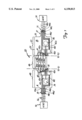
- the present invention relates to an integrated connector board 20 as shown in FIG. 1.
- the integrated connector board 20 includes a base 22 and a plurality of circuits 24a-d. Multiple circuits 24a-d are included to connect to multiple wires coupled to transducer elements on the head for reading and writing data.
- Base 22 is formed of a non-conductive material such as a polyimide material.
- the base 22 is shaped to define a main portion 28, opposed extension tabs 30 and 32, opposed mounting holes 34 and 36 and a recessed channel 38. Extension tabs 30 and 32 extend from opposed ends of the main portion 28.
- the circuits 24a-d include elongated insertion connectors 40, connector pads 42 and leads 44 formed of a conductive material.
- the elongated insertion connectors 40 and connector pads 42 are electrically coupled to one another and are electrically coupled to leads 44 via conductive paths 45 to form circuits 24a-d.
- Main portion 28 of base includes a center portion 46, and first and second side portions 48 and 50 which extend from opposed sides of the center portion 46.
- elongated insertion connectors 40 are formed on the main portion 28 and connector pads 42 are formed on both first and second side portions 48 and 50.
- Leads 44 are formed on opposed extension tabs 30 and 32.
- the design of the connector board 20 shown in FIG. 1 provides a first lead-connector pad-insertion connector circuit portion formed by tab 30, side portion 48, and center portion 46; and a second lead-connector pad-insertion connector circuit portion formed by tab 32, side portion 50, and center portion 46 to define separate operating circuit portions on connector board 20. Since center portion 46 is between side portions 48 and 50, the insertion connectors 40 on center portion 46 are coupled to connector pads 42 on both side portions 48, 50 and leads 44 on both tabs 30, 32. Preferably, the insertion connector 40 extends generally along the entire length of the center portion 46.
- a head 54 may be coupled to leads 44 on either tab 30 or 32 as desired so that wires 56 coupled to head 54 extend from either side A or B of the connector board 20 to connect to a lead-connector pad-insertion connector operating circuit portion.
- the integrated connector board 20 illustrated in FIG. 1 has multiple lead-connector pad-insertion connector operating circuit portions for use, the invention is not limited to a connector board 20 having multiple operating circuit portions.
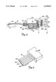
- FIG. 2 illustrates an embodiment of a testing block 60 for supporting head 54 for testing by a testing assembly incorporating a pin type connector terminal.
- Head 54 includes a slider 62, supporting transducers for reading and writing data to disc.
- Slider 62 is coupled to a gimbal spring and load beam to form HGA 64 which is supported to fly above a lower disc surface via the testing block 60.
- Testing block 60 includes a head support 66, a wire track 68, spool 70, channel 72 and head connector board mounting holes 74.
- HGA 64 is removably supported at head support 66 so that the slider 62 or head of the HGA 64 is aligned upwardly to read a disc mounted above the HGA 64.
- Wires 56 are coupled to transducers of head 54 and to leads 44 on tabs 30, 32 for providing an electrical connection to test circuitry.
- wires 56 are coupled to leads 44 via a wire bonding process.
- the integrated connector board 20 is mounted relative to the testing block 60 via mounting holes 34, 36 of connector board 20 and holes 74 on block 60.
- the testing block 60 is formed of a metal (conductive) material.
- the thickness of the base 22 of the connector board 20 of the present invention is designed to reduce the capacitance affect between the connector board 20 and testing block 60 so that the capacitance is acceptably low and does not affect the test results.
- the base 22 of the connector board 20 is formed of a non-conductive material having a thickness of 5.0 mil or thicker to reduce the capacitance effect between the connector board 20 and the testing block 60.
- the testing block 60 is coupled to an actuator assembly (not shown) via channel 72 to move HGA 64 relative to a test disc (not shown) for testing.
- Recessed channel 38 couples with channel 72 of testing block 60.
- Wires 56 extend from head 54 along wire track 68 and about spool 70 to leads 44 on connector board 20.
- Connector board 20 electrically connects wires 56 from head 54 to test circuitry.
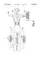
- FIG. 3 illustrates a pin type connector terminal 82 cooperating with the integrated connector board 20 for electrically connecting wires 56 of head 54 to test circuitry.
- connector terminal 82 includes an array of pins 84 for connecting multiple wires 56 to test circuitry.
- Pins 84 electrically connect to connector pads 42a-d of circuits 24a-d to provide an electrical connection between head 54 and electric circuitry of the testing apparatus.
- the terminal connector 82 (and pins 84) is designed to operate between a retracted position (shown) spaced from connector board 20 and a connected position (not shown) so that pins 84a-d contact connector pads 42a-d.
- the connector pads 42 of circuits 24a-d are aligned so that pins 84 contact connector pads 42 in the connected position (not shown).
- terminal connector 82 is moved as illustrated by arrow 86 to the connected position.
- the pins 84a-d are arranged in a rectangular shaped array and similarly connector pads 42 are arranged in a rectangular shaped array.
- the connector board 20 is designed for testing a magnetoresistive head (MR) head having an inductive write element and a MR read element. Two wires are used for the inductive write element and two wires are used for the MR read element. The four wires for the MR head are coupled to four leads 44a-d on either tab 30 or 32 which are coupled to four connector pads 42a-d. Pins 84a-d selectively couple to connector pads 42a-d on either side portion 48 or 50 to provide an electrical connection between wires of the head and the testing apparatus circuitry.
- MR magnetoresistive head
- the head support 66 is positioned on side A of block 60 and thus wires 56 of the head 54 supported thereby are coupled to leads 44 on tab 30.
- block 60 illustrated in FIG. 2, shows HGA 64 mounted on side A
- blocks 60 may include the head support 66 on either side A or B. If HGA 64 is mounted on side B (not shown), wires 56 would be connected to leads 44 on extension tab 32, and pins 84a-d of connector terminal 82 would contact connector pads 42 on side portion 50.
- a preferred embodiment of the connector board 20 allows the head to be connected to leads extending from either the left or right side of the connector board to electrically connect to connector pads 42 for coupling the head to a testing apparatus.
- holes 34 and 36 can be used to support a head connected to board 20 for transport and facilitate removal of the wires from leads 44 so that the wires are not damaged.
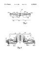
- connector board 20 of FIG. 1 having side portions 48 and 50 extending from the center portion 46 for use with an insertion type connector terminal
- connector board 20 may be severed along either lines 90--90 or 92--92 depending upon whether it is desired to have the wires 56 of the head connected to extension tab 30 or 32 to form connector board 20a of FIG. 4.
- the connector board 20 is severed to define an insertable member 94 including insertion connectors 40. If connector board 20 is severed along line 90--90, as shown in FIG.
- elongated insertion connectors 40, connective pads 42 on side portion 48 and leads 44 on tab 30 form the circuit for coupling the head wires 56 to the testing apparatus; and, if severed along line 92--92, elongated insertion connectors 40, connector pads 42 on side portion 50 and leads 44 on tab 32 form the circuits for coupling the head wires to the testing apparatus.
- a grounding bridge (not shown) is preferably soldered to leads 44a-d at either tab 30 or tab 32 to ground the head 54 for shunting the head 54 to minimize the potential for electrostatic discharge during shipping.
- bridge is coupled to leads 44a-d at tab 32.
- head wires 56 are coupled to leads 44a-d at tab 32, then bridge is coupled to leads 44a-d at tab 30.
- the connector board 20 is severed along line 92--92 for use with an insertion type connector terminal.
- the connector board 20 is severed along line 90--90 for use with an insertion type connector terminal.
- the connector board 20a of the present invention may be formed directly with an insertable member 94, an intermediate portion 95, and an extension tab 30 as shown in FIG. 4 so that the board 20 does not need to be severed to form insertable member 94.
- connector pads 42 would be formed on intermediate portion 95 and leads 44 on tab 30.
- the intermediate portion and tab 30 may extend from side A of insertable member 94 as shown in FIG. 4 or from side B of insertable member 94 (not shown).
- the insertable member 94 shown in FIG. 4 is for an MR head having four insertion connectors 40a-d for each of the MR head four wires.
- the insertion connectors 40a-d extend in spaced parallel relation from a free edge 96 along the length of insertable member 94.
- the insertable member 94 is designed for insertion into an opening 97 of an insertion type connector terminal 98 having parallely aligned spaced contacts (not shown).
- the connectors 40a-d are aligned and spaced similar to spaced contacts of the connector terminal 98 to electrically connect contacts to wires 56 coupled to connectors 40a-d via leads 44.
- the thickness of the insertion connectors 40a-d is as required inches.
- Insertion type connector terminals are incorporated into disc testing apparatus such as disc testing apparatus available from Guzik Technical Enterprises, Inc. of San Jose, Calif.
- Disc testers test upper and lower disc surfaces 102 and 104 of a disc 106 as illustrated in FIG. 6.
- disc 106 is supported for rotation about spindle axis 108 by a rotation mechanism 110.
- Upper and lower HGAs 64 are coupled to support block 112 to support the HGAs 64 relative to upper and lower disc surfaces 102 and 104.
- An actuator mechanism 113 moves block 112 to position HGAs 64 relative to selected data tracks.
- the air bearing surfaces of the slider 62 faces the disc surface 102 or 104 to fly above the disc surfaces so that the transducers can read to and write from the disc surface.
- Wires 56 of the HGAs 64 are coupled to electronic circuitry 114 of the testing apparatus via connector boards 20 (not shown) inserted into insertion type connector terminals (shown schematically) 116 coupled to electronic circuitry 114.
- the connector board 20 illustrated in FIG. 1 may be used to couple head to electronic circuitry 114.
- First and second side portions 48 and 50 of connector board 20 of FIG. 1 are mirror images.
- Upper HGA 64a is mounted to the extension tab 30 coupled to the first side portion 48
- lower HGA 64b is mounted to extension tab 32 coupled to second side portion 50.
- HGA 64a, and connector board 20a are positioned facing upwardly and HGA 64b and connector board 20b (not shown--connector board 20 severed along line 92--92) are positioned facing downwardly. Since first and second sides are mirror images, the connector boards for HGAs 64a-d have the same profile for insertion into connectors 116.
- the connector board 20 of the present invention coupled to HGAs 64 facilitates use of a test device having insertion type connector terminals as well as a test device having pin type connector terminals.
- Either embodiment of connector board 20 or 20a described and illustrated in FIGS. 1 and 4 can be used to connector to pin type connector terminals and insertion type connector terminals.
- the embodiment of connector board 20 illustrated in FIG. 1 prior to use for a insertion type connector terminal the embodiment of connector board 20 illustrated in FIG. 1, must be severed along either line 90--90 or line 92--92 to define an insertable member 94.
- multiple holes 34 and 36 may be used to secure the connector board 20 to testing block 60.
- the connector board 20 illustrated in FIG. 1 is designed for an MR head having four wires for operation.
- FIGS. 7-8 illustrate alternate embodiments of connector boards 100 and 102 for an inductive read and write head having two wires for operation and a dual strip magnetoresistive head having five wires for operation, respectively.
- Like numbers in FIGS. 7-8 refer to like parts in FIG. 1.
- connector board 100 in FIG. 7 has two circuits 24a-b; and, as shown in FIG. 8, connector board 102 has five circuits 24a-e.
- the integrated circuit board of the present invention eliminates the need to connect wires to multiple connectors to use various testing apparatus incorporating different connector terminals. Wires may be bonded to a single connector board which then can be used in multiple testing apparatus incorporating different connector terminals.
Abstract
Description
Claims (8)
Priority Applications (1)
| Application Number | Priority Date | Filing Date | Title |
|---|---|---|---|
| US09/209,136 US6150813A (en) | 1997-03-25 | 1998-12-10 | Method of connecting heads of a data storage system to a testing apparatus |
Applications Claiming Priority (3)
| Application Number | Priority Date | Filing Date | Title |
|---|---|---|---|
| US4119397P | 1997-03-25 | 1997-03-25 | |
| US08/850,202 US5876216A (en) | 1997-03-25 | 1997-05-02 | Integrated connector board for disc drive storage systems |
| US09/209,136 US6150813A (en) | 1997-03-25 | 1998-12-10 | Method of connecting heads of a data storage system to a testing apparatus |
Related Parent Applications (1)
| Application Number | Title | Priority Date | Filing Date |
|---|---|---|---|
| US08/850,202 Division US5876216A (en) | 1997-03-25 | 1997-05-02 | Integrated connector board for disc drive storage systems |
Publications (1)
| Publication Number | Publication Date |
|---|---|
| US6150813A true US6150813A (en) | 2000-11-21 |
Family
ID=26717906
Family Applications (2)
| Application Number | Title | Priority Date | Filing Date |
|---|---|---|---|
| US08/850,202 Expired - Lifetime US5876216A (en) | 1997-03-25 | 1997-05-02 | Integrated connector board for disc drive storage systems |
| US09/209,136 Expired - Fee Related US6150813A (en) | 1997-03-25 | 1998-12-10 | Method of connecting heads of a data storage system to a testing apparatus |
Family Applications Before (1)
| Application Number | Title | Priority Date | Filing Date |
|---|---|---|---|
| US08/850,202 Expired - Lifetime US5876216A (en) | 1997-03-25 | 1997-05-02 | Integrated connector board for disc drive storage systems |
Country Status (1)
| Country | Link |
|---|---|
| US (2) | US5876216A (en) |
Cited By (11)
| Publication number | Priority date | Publication date | Assignee | Title |
|---|---|---|---|---|
| US20030090836A1 (en) * | 2001-05-09 | 2003-05-15 | Stein Anatoli B. | Method and apparatus for electromagnetic interference reduction in magnetic recording devices |
| US20060232271A1 (en) * | 2005-04-15 | 2006-10-19 | Terry Farren | System, method, and apparatus for dynamic electrical testing of workpieces by multiplexing test sites with shared electronics |
| US20090158583A1 (en) * | 2007-12-19 | 2009-06-25 | Rivera Rudel P | Head gimbal assembly (HGA) connector pad alignment jig |
| US8094414B1 (en) | 2009-07-09 | 2012-01-10 | Western Digital Technologies, Inc. | Head gimbal assembly mounting mechanism |
| US8098460B1 (en) | 2009-06-30 | 2012-01-17 | Western Digital Technologies, Inc. | Dual-state clamping mechanism |
| US8218256B1 (en) | 2009-10-30 | 2012-07-10 | Western Digital Technologies, Inc. | Disk spindle assembly cartridge |
| US8270118B1 (en) | 2009-10-30 | 2012-09-18 | Western Digital Technologies, Inc. | Head stack assembly cartridge |
| US8339747B1 (en) | 2011-03-11 | 2012-12-25 | Western Digital Technologies, Inc. | Removable actuator assemblies for testing head gimbal assemblies of a storage device |
| US8419466B2 (en) * | 2011-09-13 | 2013-04-16 | Hong Fu Jin Precision Industry (Shenzhen) Co., Ltd. | Flexible printed circuit board with shielded layer of data pins |
| US8432630B1 (en) | 2010-06-30 | 2013-04-30 | Western Digital Technologies, Inc. | Disk drive component test system |
| US8705209B2 (en) | 2011-10-14 | 2014-04-22 | Western Digital Technologies, Inc. | Suspension clamp for clamping a disk drive suspension to an actuator arm |
Families Citing this family (4)
| Publication number | Priority date | Publication date | Assignee | Title |
|---|---|---|---|---|
| US6604948B1 (en) | 1999-06-09 | 2003-08-12 | Seagate Technology Llc | Double-double (2×2) tester paddle board AKA 2×2 paddle board |
| US6650506B1 (en) | 1999-12-15 | 2003-11-18 | Patrick Risse | Double-sided disk storage using a single configuration of magnetoresistive head |
| US7059868B1 (en) | 2000-03-07 | 2006-06-13 | Western Digital (Fremont), Inc. | Connection of trace circuitry in a computer disk drive system |
| JP5879663B2 (en) * | 2013-05-07 | 2016-03-08 | 住友電工プリントサーキット株式会社 | Printed wiring board for hard disk device and hard disk device |
Citations (10)
| Publication number | Priority date | Publication date | Assignee | Title |
|---|---|---|---|---|
| US3795888A (en) * | 1972-06-30 | 1974-03-05 | Motorola Inc | Printed circuit board edge connector requiring zero insertion force |
| US3848952A (en) * | 1973-07-27 | 1974-11-19 | Amp Inc | Zero insertion force edge card connector |
| US4060295A (en) * | 1976-03-15 | 1977-11-29 | Molex Incorporated | Zero insertion force printed circuit board edge connector assembly |
| US4629270A (en) * | 1984-07-16 | 1986-12-16 | Amp Incorporated | Zero insertion force card edge connector with flexible film circuitry |
| US4648668A (en) * | 1986-06-26 | 1987-03-10 | Amp Incorporated | Zero insertion force card edge connector |
| US5103359A (en) * | 1990-02-05 | 1992-04-07 | Maxtor Corporation | Connector apparatus for electrically coupling a transducer to the electronics of a magnetic recording system |
| US5121273A (en) * | 1990-04-12 | 1992-06-09 | Micropolis Corporation | Computer disk head interconnect assembly |
| US5154618A (en) * | 1991-09-30 | 1992-10-13 | Amp Incorporated | Electrical assembly |
| US5495377A (en) * | 1993-05-27 | 1996-02-27 | Seagate Technology, Inc. | Apparatus for attaching a printed circuit cable to an actuator arm in a disc drive assembly utilizing alignment pins |
| US5764497A (en) * | 1995-11-13 | 1998-06-09 | Minolta Co, Ltd. | Circuit board connection method and connection structure |
-
1997
- 1997-05-02 US US08/850,202 patent/US5876216A/en not_active Expired - Lifetime
-
1998
- 1998-12-10 US US09/209,136 patent/US6150813A/en not_active Expired - Fee Related
Patent Citations (10)
| Publication number | Priority date | Publication date | Assignee | Title |
|---|---|---|---|---|
| US3795888A (en) * | 1972-06-30 | 1974-03-05 | Motorola Inc | Printed circuit board edge connector requiring zero insertion force |
| US3848952A (en) * | 1973-07-27 | 1974-11-19 | Amp Inc | Zero insertion force edge card connector |
| US4060295A (en) * | 1976-03-15 | 1977-11-29 | Molex Incorporated | Zero insertion force printed circuit board edge connector assembly |
| US4629270A (en) * | 1984-07-16 | 1986-12-16 | Amp Incorporated | Zero insertion force card edge connector with flexible film circuitry |
| US4648668A (en) * | 1986-06-26 | 1987-03-10 | Amp Incorporated | Zero insertion force card edge connector |
| US5103359A (en) * | 1990-02-05 | 1992-04-07 | Maxtor Corporation | Connector apparatus for electrically coupling a transducer to the electronics of a magnetic recording system |
| US5121273A (en) * | 1990-04-12 | 1992-06-09 | Micropolis Corporation | Computer disk head interconnect assembly |
| US5154618A (en) * | 1991-09-30 | 1992-10-13 | Amp Incorporated | Electrical assembly |
| US5495377A (en) * | 1993-05-27 | 1996-02-27 | Seagate Technology, Inc. | Apparatus for attaching a printed circuit cable to an actuator arm in a disc drive assembly utilizing alignment pins |
| US5764497A (en) * | 1995-11-13 | 1998-06-09 | Minolta Co, Ltd. | Circuit board connection method and connection structure |
Cited By (17)
| Publication number | Priority date | Publication date | Assignee | Title |
|---|---|---|---|---|
| US20030090836A1 (en) * | 2001-05-09 | 2003-05-15 | Stein Anatoli B. | Method and apparatus for electromagnetic interference reduction in magnetic recording devices |
| US6661607B2 (en) * | 2001-05-09 | 2003-12-09 | Guzik Technical Enterprises | Method and apparatus for electromagnetic interference reduction in magnetic recording devices |
| US20060232271A1 (en) * | 2005-04-15 | 2006-10-19 | Terry Farren | System, method, and apparatus for dynamic electrical testing of workpieces by multiplexing test sites with shared electronics |
| US7288935B2 (en) | 2005-04-15 | 2007-10-30 | Hitachi Global Storage Technologies Netherlands Bv | System, method, and apparatus for dynamic electrical testing of workpieces by multiplexing test sites with shared electronics |
| US20090158583A1 (en) * | 2007-12-19 | 2009-06-25 | Rivera Rudel P | Head gimbal assembly (HGA) connector pad alignment jig |
| US8024853B2 (en) * | 2007-12-19 | 2011-09-27 | Hitachi Global Storage Technologies, Netherlands B.V. | Head gimbal assembly (HGA) connector pad alignment jig |
| US8098460B1 (en) | 2009-06-30 | 2012-01-17 | Western Digital Technologies, Inc. | Dual-state clamping mechanism |
| US8094414B1 (en) | 2009-07-09 | 2012-01-10 | Western Digital Technologies, Inc. | Head gimbal assembly mounting mechanism |
| US8218256B1 (en) | 2009-10-30 | 2012-07-10 | Western Digital Technologies, Inc. | Disk spindle assembly cartridge |
| US8270118B1 (en) | 2009-10-30 | 2012-09-18 | Western Digital Technologies, Inc. | Head stack assembly cartridge |
| US8432631B1 (en) | 2009-10-30 | 2013-04-30 | Western Digital Technologies, Inc. | Disk spindle assembly cartridge |
| US8544164B1 (en) | 2009-10-30 | 2013-10-01 | Western Digital Technologies, Inc. | Method for test mounting a head stack assembly cartridge |
| US8432630B1 (en) | 2010-06-30 | 2013-04-30 | Western Digital Technologies, Inc. | Disk drive component test system |
| US8339747B1 (en) | 2011-03-11 | 2012-12-25 | Western Digital Technologies, Inc. | Removable actuator assemblies for testing head gimbal assemblies of a storage device |
| US8419466B2 (en) * | 2011-09-13 | 2013-04-16 | Hong Fu Jin Precision Industry (Shenzhen) Co., Ltd. | Flexible printed circuit board with shielded layer of data pins |
| US8705209B2 (en) | 2011-10-14 | 2014-04-22 | Western Digital Technologies, Inc. | Suspension clamp for clamping a disk drive suspension to an actuator arm |
| US9196301B1 (en) | 2011-10-14 | 2015-11-24 | Western Digital Technologies, Inc. | Suspension clamp for clamping a disk drive suspension to an actuator arm |
Also Published As
| Publication number | Publication date |
|---|---|
| US5876216A (en) | 1999-03-02 |
Similar Documents
| Publication | Publication Date | Title |
|---|---|---|
| US6150813A (en) | Method of connecting heads of a data storage system to a testing apparatus | |
| US4645280A (en) | Solderless connection technique between data/servo flex circuits and magnetic disc heads | |
| US6025988A (en) | Interconnect adapter and head suspension assembly | |
| US6399889B1 (en) | Head interconnect circuit with alignment finger | |
| US7059868B1 (en) | Connection of trace circuitry in a computer disk drive system | |
| USRE37869E1 (en) | Head signal supply/retrieval structure for magnetic disc drive | |
| KR100357874B1 (en) | Novel scheme to avoid electrostatic discharge damage to mr/gmr head gimbal/stack assembly in hard disk application | |
| US6847505B2 (en) | Electrostatic discharge protection for disk drive integrated lead suspension | |
| US5121273A (en) | Computer disk head interconnect assembly | |
| US5969906A (en) | Transducer suspension system having access aperture | |
| US6177805B1 (en) | High density test connector for disk drives in a high volume manufacturing environment | |
| EP0888610B1 (en) | Adjustable solder bump spacer for slider-suspension attachment | |
| US7245458B2 (en) | System and method for improving the electrical connection of a hard drive relay flexible circuit assembly of an HGA flexure cable | |
| CN100426381C (en) | An improved electrical connection between a suspension flexure cable and a head stack flexure circuit | |
| US20060227461A1 (en) | Method and apparatus for providing an additional ground pad and electrical connection for grounding a magnetic recording head | |
| KR100336739B1 (en) | Converter Suspension System | |
| US20090207529A1 (en) | Flexible printed cable, head stack assembly with the same and manufacturing method thereof | |
| JPS6119083A (en) | Conductive member | |
| US6866546B2 (en) | Electrical interconnect scheme | |
| US6543673B2 (en) | Dissolving shunt connection system for ESD sensitive components | |
| EP1014342A2 (en) | Head IC, head amplifier circuit, head suspension assembly, and magnetic disk drive for avoiding electrostatic breakdown of magnetic head | |
| US5555619A (en) | Method of electrically connecting a transducer to a preamplifier | |
| KR100695789B1 (en) | Head suspension for a disk device, disk device and head ic testing method | |
| US6400529B1 (en) | Integrated circuit chip supporting and electrically connecting a head slider | |
| US20030128474A1 (en) | Low electrical impedance slider grounding |
Legal Events
| Date | Code | Title | Description |
|---|---|---|---|
| AS | Assignment |
Owner name: SEAGATE TECHNOLOGY LLC, CALIFORNIA Free format text: ASSIGNMENT OF ASSIGNORS INTEREST;ASSIGNOR:SEAGATE TECHNOLOGY, INC.;REEL/FRAME:010964/0054 Effective date: 20000628 |
|
| AS | Assignment |
Owner name: JPMORGAN CHASE BANK, AS COLLATERAL AGENT, NEW YORK Free format text: SECURITY AGREEMENT;ASSIGNOR:SEAGATE TECHNOLOGY LLC;REEL/FRAME:013177/0001 Effective date: 20020513 Owner name: JPMORGAN CHASE BANK, AS COLLATERAL AGENT,NEW YORK Free format text: SECURITY AGREEMENT;ASSIGNOR:SEAGATE TECHNOLOGY LLC;REEL/FRAME:013177/0001 Effective date: 20020513 |
|
| FPAY | Fee payment |
Year of fee payment: 4 |
|
| AS | Assignment |
Owner name: SEAGATE TECHNOLOGY LLC, CALIFORNIA Free format text: RELEASE OF SECURITY INTERESTS IN PATENT RIGHTS;ASSIGNOR:JPMORGAN CHASE BANK, N.A., AS ADMINISTRATIVE AGENT (FORMERLY KNOWN AS THE CHASE MANHATTAN BANK);REEL/FRAME:016945/0763 Effective date: 20051130 |
|
| FPAY | Fee payment |
Year of fee payment: 8 |
|
| AS | Assignment |
Owner name: JPMORGAN CHASE BANK, N.A., AS ADMINISTRATIVE AGENT Free format text: SECURITY AGREEMENT;ASSIGNORS:MAXTOR CORPORATION;SEAGATE TECHNOLOGY LLC;SEAGATE TECHNOLOGY INTERNATIONAL;REEL/FRAME:022757/0017 Effective date: 20090507 Owner name: WELLS FARGO BANK, NATIONAL ASSOCIATION, AS COLLATE Free format text: SECURITY AGREEMENT;ASSIGNORS:MAXTOR CORPORATION;SEAGATE TECHNOLOGY LLC;SEAGATE TECHNOLOGY INTERNATIONAL;REEL/FRAME:022757/0017 Effective date: 20090507 |
|
| AS | Assignment |
Owner name: SEAGATE TECHNOLOGY HDD HOLDINGS, CALIFORNIA Free format text: RELEASE;ASSIGNOR:JPMORGAN CHASE BANK, N.A., AS ADMINISTRATIVE AGENT;REEL/FRAME:025662/0001 Effective date: 20110114 Owner name: SEAGATE TECHNOLOGY LLC, CALIFORNIA Free format text: RELEASE;ASSIGNOR:JPMORGAN CHASE BANK, N.A., AS ADMINISTRATIVE AGENT;REEL/FRAME:025662/0001 Effective date: 20110114 Owner name: MAXTOR CORPORATION, CALIFORNIA Free format text: RELEASE;ASSIGNOR:JPMORGAN CHASE BANK, N.A., AS ADMINISTRATIVE AGENT;REEL/FRAME:025662/0001 Effective date: 20110114 Owner name: SEAGATE TECHNOLOGY INTERNATIONAL, CALIFORNIA Free format text: RELEASE;ASSIGNOR:JPMORGAN CHASE BANK, N.A., AS ADMINISTRATIVE AGENT;REEL/FRAME:025662/0001 Effective date: 20110114 |
|
| AS | Assignment |
Owner name: THE BANK OF NOVA SCOTIA, AS ADMINISTRATIVE AGENT, Free format text: SECURITY AGREEMENT;ASSIGNOR:SEAGATE TECHNOLOGY LLC;REEL/FRAME:026010/0350 Effective date: 20110118 |
|
| REMI | Maintenance fee reminder mailed | ||
| LAPS | Lapse for failure to pay maintenance fees | ||
| STCH | Information on status: patent discontinuation |
Free format text: PATENT EXPIRED DUE TO NONPAYMENT OF MAINTENANCE FEES UNDER 37 CFR 1.362 |
|
| FP | Lapsed due to failure to pay maintenance fee |
Effective date: 20121121 |
|
| AS | Assignment |
Owner name: SEAGATE TECHNOLOGY US HOLDINGS, INC., CALIFORNIA Free format text: TERMINATION AND RELEASE OF SECURITY INTEREST IN PATENT RIGHTS;ASSIGNOR:WELLS FARGO BANK, NATIONAL ASSOCIATION, AS COLLATERAL AGENT AND SECOND PRIORITY REPRESENTATIVE;REEL/FRAME:030833/0001 Effective date: 20130312 Owner name: SEAGATE TECHNOLOGY INTERNATIONAL, CAYMAN ISLANDS Free format text: TERMINATION AND RELEASE OF SECURITY INTEREST IN PATENT RIGHTS;ASSIGNOR:WELLS FARGO BANK, NATIONAL ASSOCIATION, AS COLLATERAL AGENT AND SECOND PRIORITY REPRESENTATIVE;REEL/FRAME:030833/0001 Effective date: 20130312 Owner name: EVAULT INC. (F/K/A I365 INC.), CALIFORNIA Free format text: TERMINATION AND RELEASE OF SECURITY INTEREST IN PATENT RIGHTS;ASSIGNOR:WELLS FARGO BANK, NATIONAL ASSOCIATION, AS COLLATERAL AGENT AND SECOND PRIORITY REPRESENTATIVE;REEL/FRAME:030833/0001 Effective date: 20130312 Owner name: SEAGATE TECHNOLOGY LLC, CALIFORNIA Free format text: TERMINATION AND RELEASE OF SECURITY INTEREST IN PATENT RIGHTS;ASSIGNOR:WELLS FARGO BANK, NATIONAL ASSOCIATION, AS COLLATERAL AGENT AND SECOND PRIORITY REPRESENTATIVE;REEL/FRAME:030833/0001 Effective date: 20130312 |