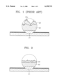
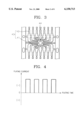
US6150713A - Lead frame for semiconductor package and lead frame plating method - Google Patents
Lead frame for semiconductor package and lead frame plating method Download PDFInfo
- Publication number
- US6150713A US6150713A US09/260,471 US26047199A US6150713A US 6150713 A US6150713 A US 6150713A US 26047199 A US26047199 A US 26047199A US 6150713 A US6150713 A US 6150713A
- Authority
- US
- United States
- Prior art keywords
- lead frame
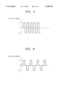
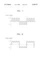
- modulated current
- metal substrate
- intermediate layer
- plating method
- Prior art date
- Legal status (The legal status is an assumption and is not a legal conclusion. Google has not performed a legal analysis and makes no representation as to the accuracy of the status listed.)
- Expired - Lifetime
Links
Images
Classifications
-
- H—ELECTRICITY
- H01—ELECTRIC ELEMENTS
- H01L—SEMICONDUCTOR DEVICES NOT COVERED BY CLASS H10
- H01L23/00—Details of semiconductor or other solid state devices
- H01L23/48—Arrangements for conducting electric current to or from the solid state body in operation, e.g. leads, terminal arrangements ; Selection of materials therefor
- H01L23/50—Arrangements for conducting electric current to or from the solid state body in operation, e.g. leads, terminal arrangements ; Selection of materials therefor for integrated circuit devices, e.g. power bus, number of leads
-
- H—ELECTRICITY
- H01—ELECTRIC ELEMENTS
- H01L—SEMICONDUCTOR DEVICES NOT COVERED BY CLASS H10
- H01L23/00—Details of semiconductor or other solid state devices
- H01L23/48—Arrangements for conducting electric current to or from the solid state body in operation, e.g. leads, terminal arrangements ; Selection of materials therefor
- H01L23/488—Arrangements for conducting electric current to or from the solid state body in operation, e.g. leads, terminal arrangements ; Selection of materials therefor consisting of soldered or bonded constructions
- H01L23/495—Lead-frames or other flat leads
- H01L23/49579—Lead-frames or other flat leads characterised by the materials of the lead frames or layers thereon
- H01L23/49582—Metallic layers on lead frames
-
- C—CHEMISTRY; METALLURGY
- C25—ELECTROLYTIC OR ELECTROPHORETIC PROCESSES; APPARATUS THEREFOR
- C25D—PROCESSES FOR THE ELECTROLYTIC OR ELECTROPHORETIC PRODUCTION OF COATINGS; ELECTROFORMING; APPARATUS THEREFOR
- C25D5/00—Electroplating characterised by the process; Pretreatment or after-treatment of workpieces
- C25D5/18—Electroplating using modulated, pulsed or reversing current
-
- C—CHEMISTRY; METALLURGY
- C25—ELECTROLYTIC OR ELECTROPHORETIC PROCESSES; APPARATUS THEREFOR
- C25D—PROCESSES FOR THE ELECTROLYTIC OR ELECTROPHORETIC PRODUCTION OF COATINGS; ELECTROFORMING; APPARATUS THEREFOR
- C25D5/00—Electroplating characterised by the process; Pretreatment or after-treatment of workpieces
- C25D5/60—Electroplating characterised by the structure or texture of the layers
- C25D5/605—Surface topography of the layers, e.g. rough, dendritic or nodular layers
- C25D5/611—Smooth layers
-
- H—ELECTRICITY
- H01—ELECTRIC ELEMENTS
- H01L—SEMICONDUCTOR DEVICES NOT COVERED BY CLASS H10
- H01L21/00—Processes or apparatus adapted for the manufacture or treatment of semiconductor or solid state devices or of parts thereof
- H01L21/02—Manufacture or treatment of semiconductor devices or of parts thereof
- H01L21/04—Manufacture or treatment of semiconductor devices or of parts thereof the devices having at least one potential-jump barrier or surface barrier, e.g. PN junction, depletion layer or carrier concentration layer
- H01L21/48—Manufacture or treatment of parts, e.g. containers, prior to assembly of the devices, using processes not provided for in a single one of the subgroups H01L21/06 - H01L21/326
- H01L21/4814—Conductive parts
- H01L21/4821—Flat leads, e.g. lead frames with or without insulating supports
-
- H—ELECTRICITY
- H01—ELECTRIC ELEMENTS
- H01L—SEMICONDUCTOR DEVICES NOT COVERED BY CLASS H10
- H01L2224/00—Indexing scheme for arrangements for connecting or disconnecting semiconductor or solid-state bodies and methods related thereto as covered by H01L24/00
- H01L2224/01—Means for bonding being attached to, or being formed on, the surface to be connected, e.g. chip-to-package, die-attach, "first-level" interconnects; Manufacturing methods related thereto
- H01L2224/42—Wire connectors; Manufacturing methods related thereto
- H01L2224/47—Structure, shape, material or disposition of the wire connectors after the connecting process
- H01L2224/48—Structure, shape, material or disposition of the wire connectors after the connecting process of an individual wire connector
- H01L2224/481—Disposition
- H01L2224/48151—Connecting between a semiconductor or solid-state body and an item not being a semiconductor or solid-state body, e.g. chip-to-substrate, chip-to-passive
- H01L2224/48221—Connecting between a semiconductor or solid-state body and an item not being a semiconductor or solid-state body, e.g. chip-to-substrate, chip-to-passive the body and the item being stacked
- H01L2224/48245—Connecting between a semiconductor or solid-state body and an item not being a semiconductor or solid-state body, e.g. chip-to-substrate, chip-to-passive the body and the item being stacked the item being metallic
- H01L2224/48247—Connecting between a semiconductor or solid-state body and an item not being a semiconductor or solid-state body, e.g. chip-to-substrate, chip-to-passive the body and the item being stacked the item being metallic connecting the wire to a bond pad of the item
-
- H—ELECTRICITY
- H01—ELECTRIC ELEMENTS
- H01L—SEMICONDUCTOR DEVICES NOT COVERED BY CLASS H10
- H01L2224/00—Indexing scheme for arrangements for connecting or disconnecting semiconductor or solid-state bodies and methods related thereto as covered by H01L24/00
- H01L2224/80—Methods for connecting semiconductor or other solid state bodies using means for bonding being attached to, or being formed on, the surface to be connected
- H01L2224/85—Methods for connecting semiconductor or other solid state bodies using means for bonding being attached to, or being formed on, the surface to be connected using a wire connector
- H01L2224/8538—Bonding interfaces outside the semiconductor or solid-state body
- H01L2224/85399—Material
- H01L2224/854—Material with a principal constituent of the material being a metal or a metalloid, e.g. boron (B), silicon (Si), germanium (Ge), arsenic (As), antimony (Sb), tellurium (Te) and polonium (Po), and alloys thereof
- H01L2224/85463—Material with a principal constituent of the material being a metal or a metalloid, e.g. boron (B), silicon (Si), germanium (Ge), arsenic (As), antimony (Sb), tellurium (Te) and polonium (Po), and alloys thereof the principal constituent melting at a temperature of greater than 1550°C
- H01L2224/85464—Palladium (Pd) as principal constituent
-
- H—ELECTRICITY
- H01—ELECTRIC ELEMENTS
- H01L—SEMICONDUCTOR DEVICES NOT COVERED BY CLASS H10
- H01L24/00—Arrangements for connecting or disconnecting semiconductor or solid-state bodies; Methods or apparatus related thereto
- H01L24/01—Means for bonding being attached to, or being formed on, the surface to be connected, e.g. chip-to-package, die-attach, "first-level" interconnects; Manufacturing methods related thereto
- H01L24/42—Wire connectors; Manufacturing methods related thereto
- H01L24/47—Structure, shape, material or disposition of the wire connectors after the connecting process
- H01L24/48—Structure, shape, material or disposition of the wire connectors after the connecting process of an individual wire connector
-
- H—ELECTRICITY
- H01—ELECTRIC ELEMENTS
- H01L—SEMICONDUCTOR DEVICES NOT COVERED BY CLASS H10
- H01L2924/00—Indexing scheme for arrangements or methods for connecting or disconnecting semiconductor or solid-state bodies as covered by H01L24/00
- H01L2924/0001—Technical content checked by a classifier
- H01L2924/00014—Technical content checked by a classifier the subject-matter covered by the group, the symbol of which is combined with the symbol of this group, being disclosed without further technical details
-
- H—ELECTRICITY
- H01—ELECTRIC ELEMENTS
- H01L—SEMICONDUCTOR DEVICES NOT COVERED BY CLASS H10
- H01L2924/00—Indexing scheme for arrangements or methods for connecting or disconnecting semiconductor or solid-state bodies as covered by H01L24/00
- H01L2924/01—Chemical elements
- H01L2924/01046—Palladium [Pd]
-
- H—ELECTRICITY
- H01—ELECTRIC ELEMENTS
- H01L—SEMICONDUCTOR DEVICES NOT COVERED BY CLASS H10
- H01L2924/00—Indexing scheme for arrangements or methods for connecting or disconnecting semiconductor or solid-state bodies as covered by H01L24/00
- H01L2924/01—Chemical elements
- H01L2924/01078—Platinum [Pt]
-
- H—ELECTRICITY
- H01—ELECTRIC ELEMENTS
- H01L—SEMICONDUCTOR DEVICES NOT COVERED BY CLASS H10
- H01L2924/00—Indexing scheme for arrangements or methods for connecting or disconnecting semiconductor or solid-state bodies as covered by H01L24/00
- H01L2924/01—Chemical elements
- H01L2924/01079—Gold [Au]
-
- H—ELECTRICITY
- H01—ELECTRIC ELEMENTS
- H01L—SEMICONDUCTOR DEVICES NOT COVERED BY CLASS H10
- H01L2924/00—Indexing scheme for arrangements or methods for connecting or disconnecting semiconductor or solid-state bodies as covered by H01L24/00
- H01L2924/10—Details of semiconductor or other solid state devices to be connected
- H01L2924/11—Device type
- H01L2924/14—Integrated circuits
Abstract
Description
Claims (17)
Applications Claiming Priority (2)
| Application Number | Priority Date | Filing Date | Title |
|---|---|---|---|
| KR1019980013927A KR100275381B1 (en) | 1998-04-18 | 1998-04-18 | Lead frame for semiconductor package and method for plating lead frame |
| KR98-13927 | 1998-04-18 |
Publications (1)
| Publication Number | Publication Date |
|---|---|
| US6150713A true US6150713A (en) | 2000-11-21 |
Family
ID=19536430
Family Applications (1)
| Application Number | Title | Priority Date | Filing Date |
|---|---|---|---|
| US09/260,471 Expired - Lifetime US6150713A (en) | 1998-04-18 | 1999-03-02 | Lead frame for semiconductor package and lead frame plating method |
Country Status (3)
| Country | Link |
|---|---|
| US (1) | US6150713A (en) |
| JP (1) | JP3502781B2 (en) |
| KR (1) | KR100275381B1 (en) |
Cited By (11)
| Publication number | Priority date | Publication date | Assignee | Title |
|---|---|---|---|---|
| US6352634B1 (en) * | 1998-06-10 | 2002-03-05 | W. C. Heraeus Gmbh & Co. Kg | Method for producing a lead-free substrate |
| US6469386B1 (en) * | 1999-10-01 | 2002-10-22 | Samsung Aerospace Industries, Ltd. | Lead frame and method for plating the same |
| US20030141567A1 (en) * | 1999-06-14 | 2003-07-31 | Salman Akram | Method of improving copper interconnects of semiconductor devices for bonding |
| EP1480270A2 (en) | 2003-05-22 | 2004-11-24 | Shinko Electric Industries Co., Ltd. | Packaging component and semiconductor package |
| US20060231931A1 (en) * | 2005-04-15 | 2006-10-19 | Samsung Techwin Co., Ltd. | Lead frame for semiconductor package |
| US20080176095A1 (en) * | 2003-02-19 | 2008-07-24 | Mark Fery | Thermal interconnect systems methods of production and uses thereof |
| US20110272184A1 (en) * | 2008-09-05 | 2011-11-10 | Lg Innotek Co., Ltd. | Lead frame and manufacturing method thereof |
| US20120001307A1 (en) * | 2009-03-12 | 2012-01-05 | Lg Innotek Co., Ltd. | Lead Frame and Method For Manufacturing the Same |
| CN103617969A (en) * | 2013-12-04 | 2014-03-05 | 广州先艺电子科技有限公司 | Heat sink welded with gold and tin alloy thin film and manufacturing method of heat sink |
| WO2015188971A1 (en) * | 2014-06-13 | 2015-12-17 | Robert Bosch Gmbh | Substrate with a surface coating and method for coating a surface of a substrate |
| CN110192268A (en) * | 2016-10-20 | 2019-08-30 | Ih知识产权控股有限公司 | Method of the plating metal substrate to obtain required surface roughness |
Families Citing this family (2)
| Publication number | Priority date | Publication date | Assignee | Title |
|---|---|---|---|---|
| KR20020094965A (en) * | 2001-06-12 | 2002-12-20 | 앰코 테크놀로지 코리아 주식회사 | Lead frame and semiconductor package using it |
| KR101021600B1 (en) * | 2001-07-09 | 2011-03-17 | 스미토모 긴조쿠 고잔 가부시키가이샤 | Lead frame and its manufacturing method |
Citations (12)
| Publication number | Priority date | Publication date | Assignee | Title |
|---|---|---|---|---|
| JPH07326702A (en) * | 1994-06-02 | 1995-12-12 | Hitachi Cable Ltd | Manufacturing method of leadframe for semiconductor device |
| US5510197A (en) * | 1993-04-28 | 1996-04-23 | Mitsubishi Shindoh Co., Ltd. | Lead frame material and lead frame for semiconductor device |
| JPH0929865A (en) * | 1995-07-20 | 1997-02-04 | Nippon Dennetsu Co Ltd | Corrugated board paper, housing box using the paper, and corrugated board paper cutting jig |
| US5650661A (en) * | 1993-12-27 | 1997-07-22 | National Semiconductor Corporation | Protective coating combination for lead frames |
| US5760468A (en) * | 1994-09-14 | 1998-06-02 | Micron Technology, Inc. | Adhesion enhanced semiconductor die for mold compound packaging |
| US5767574A (en) * | 1996-03-26 | 1998-06-16 | Samsung Aerospace Industries, Ltd. | Semiconductor lead frame |
| US5801436A (en) * | 1995-12-20 | 1998-09-01 | Serizawa; Seiichi | Lead frame for semiconductor device and process for producing the same |
| US5914532A (en) * | 1996-04-30 | 1999-06-22 | Sony Corporation | Lead frame, method for manufacturing the same, and semiconductor device employing the same |
| US5977620A (en) * | 1997-05-20 | 1999-11-02 | Samsung Aerospace Industries, Ltd. | Lead frame having a Ni-Mn alloy layer and a Pd layer |
| US5994767A (en) * | 1997-04-09 | 1999-11-30 | Sitron Precision Co., Ltd. | Leadframe for integrated circuit package and method of manufacturing the same |
| US6034422A (en) * | 1995-09-29 | 2000-03-07 | Dai Nippon Printing Co., Ltd. | Lead frame, method for partial noble plating of said lead frame and semiconductor device having said lead frame |
| US6037653A (en) * | 1997-03-25 | 2000-03-14 | Samsung Aerospace Industries, Ltd. | Semiconductor lead frame having multi-layered plating layer including copper-nickel plating layer |
-
1998
- 1998-04-18 KR KR1019980013927A patent/KR100275381B1/en not_active IP Right Cessation
-
1999
- 1999-03-01 JP JP05236299A patent/JP3502781B2/en not_active Expired - Lifetime
- 1999-03-02 US US09/260,471 patent/US6150713A/en not_active Expired - Lifetime
Patent Citations (12)
| Publication number | Priority date | Publication date | Assignee | Title |
|---|---|---|---|---|
| US5510197A (en) * | 1993-04-28 | 1996-04-23 | Mitsubishi Shindoh Co., Ltd. | Lead frame material and lead frame for semiconductor device |
| US5650661A (en) * | 1993-12-27 | 1997-07-22 | National Semiconductor Corporation | Protective coating combination for lead frames |
| JPH07326702A (en) * | 1994-06-02 | 1995-12-12 | Hitachi Cable Ltd | Manufacturing method of leadframe for semiconductor device |
| US5760468A (en) * | 1994-09-14 | 1998-06-02 | Micron Technology, Inc. | Adhesion enhanced semiconductor die for mold compound packaging |
| JPH0929865A (en) * | 1995-07-20 | 1997-02-04 | Nippon Dennetsu Co Ltd | Corrugated board paper, housing box using the paper, and corrugated board paper cutting jig |
| US6034422A (en) * | 1995-09-29 | 2000-03-07 | Dai Nippon Printing Co., Ltd. | Lead frame, method for partial noble plating of said lead frame and semiconductor device having said lead frame |
| US5801436A (en) * | 1995-12-20 | 1998-09-01 | Serizawa; Seiichi | Lead frame for semiconductor device and process for producing the same |
| US5767574A (en) * | 1996-03-26 | 1998-06-16 | Samsung Aerospace Industries, Ltd. | Semiconductor lead frame |
| US5914532A (en) * | 1996-04-30 | 1999-06-22 | Sony Corporation | Lead frame, method for manufacturing the same, and semiconductor device employing the same |
| US6037653A (en) * | 1997-03-25 | 2000-03-14 | Samsung Aerospace Industries, Ltd. | Semiconductor lead frame having multi-layered plating layer including copper-nickel plating layer |
| US5994767A (en) * | 1997-04-09 | 1999-11-30 | Sitron Precision Co., Ltd. | Leadframe for integrated circuit package and method of manufacturing the same |
| US5977620A (en) * | 1997-05-20 | 1999-11-02 | Samsung Aerospace Industries, Ltd. | Lead frame having a Ni-Mn alloy layer and a Pd layer |
Cited By (36)
| Publication number | Priority date | Publication date | Assignee | Title |
|---|---|---|---|---|
| US6352634B1 (en) * | 1998-06-10 | 2002-03-05 | W. C. Heraeus Gmbh & Co. Kg | Method for producing a lead-free substrate |
| US7338889B2 (en) | 1999-06-14 | 2008-03-04 | Micron Technology, Inc. | Method of improving copper interconnects of semiconductor devices for bonding |
| US20060055057A1 (en) * | 1999-06-14 | 2006-03-16 | Salman Akram | Copper interconnect |
| US20040171246A1 (en) * | 1999-06-14 | 2004-09-02 | Salman Akram | Method of improving copper interconnect of semiconductor devices for bonding |
| US7511363B2 (en) * | 1999-06-14 | 2009-03-31 | Micron Technology, Inc. | Copper interconnect |
| US8759970B2 (en) | 1999-06-14 | 2014-06-24 | Round Rock Research, Llc | Semiconductor device having copper interconnect for bonding |
| US7345358B2 (en) | 1999-06-14 | 2008-03-18 | Micron Technology, Inc. | Copper interconnect for semiconductor device |
| US20050212128A1 (en) * | 1999-06-14 | 2005-09-29 | Salman Akram | Copper interconnect |
| US20050218483A1 (en) * | 1999-06-14 | 2005-10-06 | Salman Akram | Method and semiconductor device having copper interconnect for bonding |
| US20060055059A1 (en) * | 1999-06-14 | 2006-03-16 | Salman Akram | Copper interconnect |
| US7489041B2 (en) | 1999-06-14 | 2009-02-10 | Micron Technology, Inc. | Copper interconnect |
| US20060055060A1 (en) * | 1999-06-14 | 2006-03-16 | Salman Akram | Copper interconnect |
| US20060055058A1 (en) * | 1999-06-14 | 2006-03-16 | Salman Akram | Copper interconnect |
| US20060071336A1 (en) * | 1999-06-14 | 2006-04-06 | Salman Akram | Copper interconnect |
| US20060138660A1 (en) * | 1999-06-14 | 2006-06-29 | Salman Akram | Copper interconnect |
| US20030141567A1 (en) * | 1999-06-14 | 2003-07-31 | Salman Akram | Method of improving copper interconnects of semiconductor devices for bonding |
| US7592246B2 (en) | 1999-06-14 | 2009-09-22 | Micron Technology, Inc. | Method and semiconductor device having copper interconnect for bonding |
| US7569934B2 (en) | 1999-06-14 | 2009-08-04 | Micron Technology, Inc. | Copper interconnect |
| US6469386B1 (en) * | 1999-10-01 | 2002-10-22 | Samsung Aerospace Industries, Ltd. | Lead frame and method for plating the same |
| US7897437B2 (en) | 2003-02-19 | 2011-03-01 | Honeywell International Inc. | Thermal interconnect systems methods of production and uses thereof |
| US20080176095A1 (en) * | 2003-02-19 | 2008-07-24 | Mark Fery | Thermal interconnect systems methods of production and uses thereof |
| US20040232534A1 (en) * | 2003-05-22 | 2004-11-25 | Shinko Electric Industries, Co., Ltd. | Packaging component and semiconductor package |
| CN100433300C (en) * | 2003-05-22 | 2008-11-12 | 新光电气工业株式会社 | Packaging component and semiconductor package |
| EP1480270A3 (en) * | 2003-05-22 | 2005-07-13 | Shinko Electric Industries Co., Ltd. | Packaging component and semiconductor package |
| EP1480270A2 (en) | 2003-05-22 | 2004-11-24 | Shinko Electric Industries Co., Ltd. | Packaging component and semiconductor package |
| US7190057B2 (en) | 2003-05-22 | 2007-03-13 | Shinko Electric Industries Co., Ltd. | Packaging component and semiconductor package |
| US7285845B2 (en) | 2005-04-15 | 2007-10-23 | Samsung Techwin Co., Ltd. | Lead frame for semiconductor package |
| US20060231931A1 (en) * | 2005-04-15 | 2006-10-19 | Samsung Techwin Co., Ltd. | Lead frame for semiconductor package |
| US20110272184A1 (en) * | 2008-09-05 | 2011-11-10 | Lg Innotek Co., Ltd. | Lead frame and manufacturing method thereof |
| US8945951B2 (en) * | 2008-09-05 | 2015-02-03 | Lg Innotek Co., Ltd. | Lead frame and manufacturing method thereof |
| US20120001307A1 (en) * | 2009-03-12 | 2012-01-05 | Lg Innotek Co., Ltd. | Lead Frame and Method For Manufacturing the Same |
| US8564107B2 (en) * | 2009-03-12 | 2013-10-22 | Lg Innotek Co., Ltd. | Lead frame and method for manufacturing the same |
| CN103617969A (en) * | 2013-12-04 | 2014-03-05 | 广州先艺电子科技有限公司 | Heat sink welded with gold and tin alloy thin film and manufacturing method of heat sink |
| CN103617969B (en) * | 2013-12-04 | 2016-06-29 | 广州先艺电子科技有限公司 | A kind of weld the heat sink and preparation method thereof of gold-tin alloy thin film |
| WO2015188971A1 (en) * | 2014-06-13 | 2015-12-17 | Robert Bosch Gmbh | Substrate with a surface coating and method for coating a surface of a substrate |
| CN110192268A (en) * | 2016-10-20 | 2019-08-30 | Ih知识产权控股有限公司 | Method of the plating metal substrate to obtain required surface roughness |
Also Published As
| Publication number | Publication date |
|---|---|
| JPH11307711A (en) | 1999-11-05 |
| JP3502781B2 (en) | 2004-03-02 |
| KR100275381B1 (en) | 2000-12-15 |
| KR19990080573A (en) | 1999-11-15 |
Similar Documents
| Publication | Publication Date | Title |
|---|---|---|
| KR100371567B1 (en) | Ag pre-plated lead frame for semiconductor package | |
| US5906312A (en) | Solder bump for flip chip assembly and method of its fabrication | |
| JP3760075B2 (en) | Lead frame for semiconductor packages | |
| EP1480270B1 (en) | Packaging component and semiconductor package | |
| KR960002495B1 (en) | Semiconductor device having improved leads | |
| US6150713A (en) | Lead frame for semiconductor package and lead frame plating method | |
| US7245006B2 (en) | Palladium-spot leadframes for high adhesion semiconductor devices and method of fabrication | |
| US6713852B2 (en) | Semiconductor leadframes plated with thick nickel, minimum palladium, and pure tin | |
| US7148085B2 (en) | Gold spot plated leadframes for semiconductor devices and method of fabrication | |
| CA2118758C (en) | Lead frame for integrated circuits | |
| US6376901B1 (en) | Palladium-spot leadframes for solder plated semiconductor devices and method of fabrication | |
| US6995042B2 (en) | Method for fabricating preplated nickel/palladium and tin leadframes | |
| US6545344B2 (en) | Semiconductor leadframes plated with lead-free solder and minimum palladium | |
| JP2002076229A (en) | Lead frame for semiconductor containing silver-plated part and its manufacturing method | |
| US5780931A (en) | Surface mounting semiconductor device and semiconductor mounting component | |
| US5935719A (en) | Lead-free, nickel-free and cyanide-free plating finish for semiconductor leadframes | |
| KR100378489B1 (en) | Ag or Ag-alloy plated Lead frame for semiconductor package and the method of manufacturing the same | |
| JP2001060649A (en) | Manufacture of plating electronic termination | |
| US6323544B1 (en) | Plated leadframes with cantilevered leads | |
| KR100231832B1 (en) | Semiconductor lead frame with multi-plating layer | |
| KR100209264B1 (en) | Semiconductor lead frame | |
| KR100203334B1 (en) | Multi-layer plateded lead frame | |
| KR100450090B1 (en) | Lead frame of semiconductor package and method of plating the same | |
| JPH04174546A (en) | Manufacture of semiconductor lead frame | |
| JPH08316394A (en) | Semiconductor device |
Legal Events
| Date | Code | Title | Description |
|---|---|---|---|
| AS | Assignment |
Owner name: SAMSUNG AEROSPACE INDUSTRIES, LTD., KOREA, REPUBLI Free format text: ASSIGNMENT OF ASSIGNORS INTEREST;ASSIGNORS:PARK, SE-CHUL;LEE, KYU-HAN;KIM, JU-BONG;AND OTHERS;REEL/FRAME:009807/0459 Effective date: 19990225 |
|
| STCF | Information on status: patent grant |
Free format text: PATENTED CASE |
|
| FEPP | Fee payment procedure |
Free format text: PAYOR NUMBER ASSIGNED (ORIGINAL EVENT CODE: ASPN); ENTITY STATUS OF PATENT OWNER: LARGE ENTITY |
|
| FPAY | Fee payment |
Year of fee payment: 4 |
|
| FPAY | Fee payment |
Year of fee payment: 8 |
|
| FEPP | Fee payment procedure |
Free format text: PAYOR NUMBER ASSIGNED (ORIGINAL EVENT CODE: ASPN); ENTITY STATUS OF PATENT OWNER: LARGE ENTITY Free format text: PAYER NUMBER DE-ASSIGNED (ORIGINAL EVENT CODE: RMPN); ENTITY STATUS OF PATENT OWNER: LARGE ENTITY |
|
| FPAY | Fee payment |
Year of fee payment: 12 |
|
| AS | Assignment |
Owner name: MDS CO. LTD., KOREA, REPUBLIC OF Free format text: ASSIGNMENT OF ASSIGNORS INTEREST;ASSIGNOR:SAMSUNG TECHWIN CO., LTD.;REEL/FRAME:033327/0442 Effective date: 20140430 |
|
| AS | Assignment |
Owner name: HAESUNG DS CO., LTD., KOREA, REPUBLIC OF Free format text: CHANGE OF NAME;ASSIGNOR:MDS CO. LTD.;REEL/FRAME:035475/0415 Effective date: 20140901 |