US6149817A - Shell-less hollow fiber membrane fluid contactor - Google Patents
Shell-less hollow fiber membrane fluid contactor Download PDFInfo
- Publication number
- US6149817A US6149817A US09/265,064 US26506499A US6149817A US 6149817 A US6149817 A US 6149817A US 26506499 A US26506499 A US 26506499A US 6149817 A US6149817 A US 6149817A
- Authority
- US
- United States
- Prior art keywords
- fluid
- shell
- hollow fiber
- contactor
- fiber membrane
- Prior art date
- Legal status (The legal status is an assumption and is not a legal conclusion. Google has not performed a legal analysis and makes no representation as to the accuracy of the status listed.)
- Expired - Lifetime
Links
- 239000012530 fluid Substances 0.000 title claims abstract description 358
- 239000012528 membrane Substances 0.000 title claims abstract description 127
- 239000012510 hollow fiber Substances 0.000 title claims abstract description 109
- 238000009826 distribution Methods 0.000 claims abstract description 69
- 238000000034 method Methods 0.000 claims abstract description 27
- 230000008569 process Effects 0.000 claims abstract description 21
- 238000009792 diffusion process Methods 0.000 claims abstract description 13
- 238000012545 processing Methods 0.000 claims abstract description 9
- 239000000835 fiber Substances 0.000 claims description 25
- 238000012546 transfer Methods 0.000 claims description 23
- 238000007599 discharging Methods 0.000 claims description 18
- 238000007789 sealing Methods 0.000 claims description 16
- 230000004888 barrier function Effects 0.000 claims description 14
- 238000004891 communication Methods 0.000 claims description 11
- 230000000694 effects Effects 0.000 claims description 5
- 239000007788 liquid Substances 0.000 description 25
- 239000007789 gas Substances 0.000 description 20
- XLYOFNOQVPJJNP-UHFFFAOYSA-N water Substances O XLYOFNOQVPJJNP-UHFFFAOYSA-N 0.000 description 13
- 239000000463 material Substances 0.000 description 12
- 238000000926 separation method Methods 0.000 description 10
- 239000000356 contaminant Substances 0.000 description 9
- 239000011148 porous material Substances 0.000 description 8
- 230000002745 absorbent Effects 0.000 description 5
- 239000002250 absorbent Substances 0.000 description 5
- 239000003960 organic solvent Substances 0.000 description 5
- 238000004382 potting Methods 0.000 description 5
- 239000011347 resin Substances 0.000 description 5
- 229920005989 resin Polymers 0.000 description 5
- 230000008878 coupling Effects 0.000 description 4
- 238000010168 coupling process Methods 0.000 description 4
- 238000005859 coupling reaction Methods 0.000 description 4
- 238000000605 extraction Methods 0.000 description 4
- 239000012071 phase Substances 0.000 description 4
- 238000007872 degassing Methods 0.000 description 3
- 230000002209 hydrophobic effect Effects 0.000 description 3
- 239000012535 impurity Substances 0.000 description 3
- 239000000126 substance Substances 0.000 description 3
- 239000002699 waste material Substances 0.000 description 3
- IJGRMHOSHXDMSA-UHFFFAOYSA-N Atomic nitrogen Chemical compound N#N IJGRMHOSHXDMSA-UHFFFAOYSA-N 0.000 description 2
- QVGXLLKOCUKJST-UHFFFAOYSA-N atomic oxygen Chemical compound [O] QVGXLLKOCUKJST-UHFFFAOYSA-N 0.000 description 2
- 238000010276 construction Methods 0.000 description 2
- 230000007613 environmental effect Effects 0.000 description 2
- 239000003344 environmental pollutant Substances 0.000 description 2
- 229910017053 inorganic salt Inorganic materials 0.000 description 2
- 238000004519 manufacturing process Methods 0.000 description 2
- 239000001301 oxygen Substances 0.000 description 2
- 229910052760 oxygen Inorganic materials 0.000 description 2
- 231100000719 pollutant Toxicity 0.000 description 2
- 150000003839 salts Chemical class 0.000 description 2
- 231100000331 toxic Toxicity 0.000 description 2
- 230000002588 toxic effect Effects 0.000 description 2
- 239000004743 Polypropylene Substances 0.000 description 1
- 238000007792 addition Methods 0.000 description 1
- 230000000903 blocking effect Effects 0.000 description 1
- 239000006227 byproduct Substances 0.000 description 1
- 238000004140 cleaning Methods 0.000 description 1
- 239000002131 composite material Substances 0.000 description 1
- 230000003247 decreasing effect Effects 0.000 description 1
- 238000012217 deletion Methods 0.000 description 1
- 230000037430 deletion Effects 0.000 description 1
- 238000013461 design Methods 0.000 description 1
- 230000009699 differential effect Effects 0.000 description 1
- 239000006185 dispersion Substances 0.000 description 1
- 230000008030 elimination Effects 0.000 description 1
- 238000003379 elimination reaction Methods 0.000 description 1
- 230000007717 exclusion Effects 0.000 description 1
- 238000003780 insertion Methods 0.000 description 1
- 230000037431 insertion Effects 0.000 description 1
- 238000009434 installation Methods 0.000 description 1
- 239000007791 liquid phase Substances 0.000 description 1
- 238000012423 maintenance Methods 0.000 description 1
- 239000002184 metal Substances 0.000 description 1
- 229910052751 metal Inorganic materials 0.000 description 1
- 150000002739 metals Chemical class 0.000 description 1
- 239000000203 mixture Substances 0.000 description 1
- 238000012986 modification Methods 0.000 description 1
- 230000004048 modification Effects 0.000 description 1
- 229910052757 nitrogen Inorganic materials 0.000 description 1
- 231100000252 nontoxic Toxicity 0.000 description 1
- 230000003000 nontoxic effect Effects 0.000 description 1
- 238000012856 packing Methods 0.000 description 1
- 239000002245 particle Substances 0.000 description 1
- 239000013618 particulate matter Substances 0.000 description 1
- 230000035699 permeability Effects 0.000 description 1
- 239000004033 plastic Substances 0.000 description 1
- 229920003023 plastic Polymers 0.000 description 1
- 229920000098 polyolefin Polymers 0.000 description 1
- -1 polypropylene Polymers 0.000 description 1
- 229920001155 polypropylene Polymers 0.000 description 1
- 230000008439 repair process Effects 0.000 description 1
- 239000007787 solid Substances 0.000 description 1
- 239000002904 solvent Substances 0.000 description 1
- 229920001169 thermoplastic Polymers 0.000 description 1
- 229920001187 thermosetting polymer Polymers 0.000 description 1
- 239000004416 thermosoftening plastic Substances 0.000 description 1
- 239000003053 toxin Substances 0.000 description 1
- 231100000765 toxin Toxicity 0.000 description 1
- 108700012359 toxins Proteins 0.000 description 1
Images


Classifications
-
- B—PERFORMING OPERATIONS; TRANSPORTING
- B01—PHYSICAL OR CHEMICAL PROCESSES OR APPARATUS IN GENERAL
- B01D—SEPARATION
- B01D63/00—Apparatus in general for separation processes using semi-permeable membranes
- B01D63/02—Hollow fibre modules
- B01D63/04—Hollow fibre modules comprising multiple hollow fibre assemblies
- B01D63/043—Hollow fibre modules comprising multiple hollow fibre assemblies with separate tube sheets
-
- B—PERFORMING OPERATIONS; TRANSPORTING
- B01—PHYSICAL OR CHEMICAL PROCESSES OR APPARATUS IN GENERAL
- B01D—SEPARATION
- B01D19/00—Degasification of liquids
- B01D19/0031—Degasification of liquids by filtration
-
- B—PERFORMING OPERATIONS; TRANSPORTING
- B01—PHYSICAL OR CHEMICAL PROCESSES OR APPARATUS IN GENERAL
- B01D—SEPARATION
- B01D53/00—Separation of gases or vapours; Recovering vapours of volatile solvents from gases; Chemical or biological purification of waste gases, e.g. engine exhaust gases, smoke, fumes, flue gases, aerosols
- B01D53/22—Separation of gases or vapours; Recovering vapours of volatile solvents from gases; Chemical or biological purification of waste gases, e.g. engine exhaust gases, smoke, fumes, flue gases, aerosols by diffusion
-
- B—PERFORMING OPERATIONS; TRANSPORTING
- B01—PHYSICAL OR CHEMICAL PROCESSES OR APPARATUS IN GENERAL
- B01D—SEPARATION
- B01D61/00—Processes of separation using semi-permeable membranes, e.g. dialysis, osmosis or ultrafiltration; Apparatus, accessories or auxiliary operations specially adapted therefor
- B01D61/24—Dialysis ; Membrane extraction
- B01D61/28—Apparatus therefor
-
- B—PERFORMING OPERATIONS; TRANSPORTING
- B01—PHYSICAL OR CHEMICAL PROCESSES OR APPARATUS IN GENERAL
- B01D—SEPARATION
- B01D63/00—Apparatus in general for separation processes using semi-permeable membranes
- B01D63/02—Hollow fibre modules
-
- B—PERFORMING OPERATIONS; TRANSPORTING
- B01—PHYSICAL OR CHEMICAL PROCESSES OR APPARATUS IN GENERAL
- B01D—SEPARATION
- B01D2313/00—Details relating to membrane modules or apparatus
- B01D2313/10—Specific supply elements
Definitions
- the present invention relates generally to membrane contactors for fluid separation and processing, and more particularly to shell-less hollow fiber membrane contactors and methods of fluid processing utilizing shell-less hollow fiber membrane contactors.
- Membrane contactors provide a means of accomplishing gas/liquid, and liquid/liquid (which can encompass liquid/dissolved solid) separations.
- Membrane contactors typically are used to bring two immiscible fluid phases-for example, a first liquid and a second liquid, or a gas and a liquid-into contact with one another to effect separation and/or transfer of one or more components from one fluid to the other.
- a membrane contactor is a modular device, commonly including a bundle of microporous hollow fibers.
- Membrane contactors typically include a rigid shell or housing enclosing the fiber bundle.
- the shell typically is provided with four fluid ports: an inlet for introducing the first fluid, an outlet for discharging the first fluid, an inlet for introducing the second fluid, and an outlet for discharging the second fluid.
- the hollow fibers are potted on both ends, within the housing, to form polymeric tube sheets with the fiber bores opening on each end into common first and second end cap portions of the shell.
- the first end cap contains the inlet for the first fluid, which is designated the "tube-side” or "lumen-side” fluid because it is the fluid that passes through the internal lumens of the fibers.
- the second end cap contains the outlet for discharging the lumen-side fluid.
- the second fluid designated the "shell-side” fluid
- the shell-side fluid typically enters and exits the housing through inlet and outlet ports arranged between the tube sheets, whereby the shell-side fluid contacts the external surfaces of the fibers.
- the shell-side fluid flows through the interstices between fibers of the fiber bundle, and may be directed to flow parallel or perpendicular to the fiber length.
- the tube sheets separate the lumen-side fluid from the shell-side fluid, the lumen-side fluid does not mix with the shell-side fluid, and the only transfer between the lumen-side fluid and the shell-side fluid occurs through the walls of the fibers.
- the fine pores in the fiber wall are normally filled with a stationary layer of one of the two fluids, the other fluid being excluded from the pores due to surface tension and/or pressure differential effects. Mass transfer and separation are caused by diffusion, which is driven by the difference in concentration of the transferring species between the two phases. Typically, no convective or bulk flow occurs across the membrane.
- membrane contactors are typically fabricated with hydrophobic hollow fiber microporous membranes. Since the membranes are hydrophobic and have very small pores, liquid will not easily pass through the pores. The membranes act as an inert support that brings the liquid and gas phases into direct contact, without dispersion. The mass transfer between the two phases is governed by the difference in partial pressure of the gas species being transferred.
- the liquid/liquid interface at each pore is typically immobilized by the appropriate selection of membrane and liquid phase pressures.
- the membrane also acts as an inert support to facilitate direct contacting of two immiscible phases without mixing.
- Membrane contactors can be utilized for a variety of applications, including the separation of a component from a fluid or transferring a component of one fluid to another.
- a membrane contactor can be used in removal of contaminants from an effluent stream.
- a contaminated effluent stream is generated as a by-product.
- Existing industrial processes frequently must be upgraded to reduce environmental emissions and/or increase efficiency. Therefore, a need often arises for a process and system that can be economically retrofit to an existing plant to reduce emissions.
- membrane contactors Several factors are important in the design of membrane contactors, including separation characteristics, cost, pressure drop, weight, and efficiency.
- the pressure drop across a contactor should be low to reduce the need for more expensive high pressure equipment. Low pressure drop is of particular importance in retrofit projects where a membrane contactor is to be added at the discharge point of an effluent process stream, as the process pressure at this point is typically at or near atmospheric pressure. High efficiency of mass transfer is desirable for reducing the size of the contactor. Low weight is desirable for decreasing installation and maintenance costs, and is of particular importance in offshore applications.
- Existing membrane contactors have been found less than fully satisfactory in meeting these goals. For example, the shell portion of typical membrane contactors adds considerably to their weight and expense. Shell-type contactors also typically must operate at elevated pressures. Accordingly, a need exists for a membrane contactor having improved characteristics over known membrane contactors.
- the present invention provides a simple, low cost, efficient membrane contactor having no outer shell or housing.
- the absence of a shell allows the contactor of the present invention to be readily added at or near the discharge point of an effluent stream to remove contaminant or otherwise process the stream by membrane-aided diffusion.
- the membrane contactor of the present invention generates little or no back-pressure in operation, thereby minimizing any associated pressure drop and reducing the need for additional pumps, fans or other motive means. Absence of a shell also reduces weight and material cost.
- a shell-side fluid from an external source enters the contactor through a fluid distribution element around which at least one and preferably a bundle of hollow fiber membranes is assembled.
- the shell-side fluid is discharged from the fluid distribution element into contact with the external surfaces of the hollow fiber membranes.
- the hollow fibers can be open on one end into a single common end cap; or alternatively, open at both ends into two separate end caps, one end cap provided at each end of the fibers.
- the hollow fibers can be arranged in a generally U-shaped array, with their inlets adjacent their outlets.
- a tube sheet or other barrier provides a fluid-tight seal separating the shell-side fluid from the lumen-side fluid carried within the lumens of the hollow fiber membranes.
- the tube sheets preferably are permanently attached to the fluid distribution element, which serves to support the tube sheets rigidly in position.
- One or more end caps can be permanently attached to the fluid distribution element and/or tube sheets, thereby forming a part of the membrane contactor.
- the membrane contactor can take the form of a replaceable cartridge, releasably connectable to external end cap(s) or other external structure of a fluid delivery system, through fluid-tight releasable sealing means, such as for example, a gasket or O-ring and a releasable clamp or connector.
- fluid-tight releasable sealing means such as for example, a gasket or O-ring and a releasable clamp or connector.
- the membrane contactor of the present invention is applicable to a variety of uses, including without limitation: the separation of one or more components from a fluid; transferring a component of one fluid to another fluid; separation of impurities or toxins from contaminated process water, waste gasses or other fluids; degassing liquids by vacuum or sweep fluid; selective extraction of organics from aqueous fluids; and extraction of dissolved inorganic salts from organic solvents.
- one aspect of the present invention provides a shell-less fluid contactor including a fluid distribution element having at least one inlet for receiving a shell-side fluid, and at least one outlet for discharging the shell-side fluid.
- the contactor preferably further includes at least one hollow fiber membrane having a microporous wall, the microporous wall having an internal surface defining a lumen and an external surface exposed to contact with the shell-side fluid, each hollow fiber membrane further comprising a first port in fluid communication with the lumen.
- the contactor preferably further includes a barrier for separating the first port of each hollow fiber membrane from the shell-side fluid.
- the present invention provides a fluid contactor for transferring at least one component of a shell-side fluid to a lumen-side fluid.
- the fluid contactor preferably includes a substantially rigid fluid distribution tube having a wall defining an external surface and an internal passage, an open first end in fluid communication with the internal passage and forming an inlet for receiving a shell-side fluid, and a closed second end opposite the first end.
- the wall of the fluid distribution tube preferably includes a perforated wall section having a plurality of discharge openings for discharging the shell-side fluid from the internal passage.
- the fluid contactor preferably also includes a tube sheet mounted in sealing engagement with the external surface of the fluid distribution tube between the first end of the fluid distribution tube and the perforated wall section, and a support member mounted to the fluid distribution tube adjacent the second end thereof.
- the fluid contactor preferably also includes a plurality of hollow fiber membranes surrounding the fluid distribution tube, each hollow fiber membrane having a first end, a second end, an internal lumen for transmitting a lumen-side fluid, and an external surface.
- the first end of each hollow fiber membrane preferably extends sealingly through the tube sheet, the second end of each hollow fiber membrane is attached to said support member, and at least a portion of the external surface of each hollow fiber membrane is exposed to the ambient.
- the support member comprises a closure block for closing the second ends of the hollow fiber membranes to passage of the lumen-side fluid.
- the support member comprises a second tube sheet providing passage of the lumen-side fluid through ports in the second ends of the hollow fiber membranes.
- the present invention provides a multi-stage assembly for fluid processing.
- the assembly includes a first stage comprising a first shell-less fluid contactor having a fluid distribution element with at least one inlet for receiving a shell-side fluid, and at least one outlet for discharging the shell-side fluid.
- the first shell-less fluid contactor also includes at least one hollow fiber membrane having a microporous wall with an internal surface defining a lumen and an external surface exposed to contact with the shell-side fluid. Each hollow fiber membrane has a first port in fluid communication with the lumen.
- the first shell-less fluid contactor also includes a barrier for separating the first port of each said at least one hollow fiber membrane from the shell-side fluid.
- the assembly preferably also includes a second stage comprising a second fluid contactor.
- the second fluid contactor includes a fluid distribution element having at least one inlet for receiving a shell-side fluid, and at least one outlet for discharging the shell-side fluid.
- the second fluid contactor also includes at least one hollow fiber membrane with a microporous wall, the microporous wall having an internal surface defining a lumen and an external surface exposed to contact with the shell-side fluid. Each hollow fiber membrane also has a first port in fluid communication with the lumen.
- the second fluid contactor also includes a barrier for separating the first port of each hollow fiber membrane from the shell-side fluid.
- the assembly preferably also includes collection and transfer means for collecting the shell-side fluid discharged from the at least one outlet of the first fluid contactor, and transferring the collected shell-side fluid to the at least one inlet of the second fluid contactor.
- collection and transfer means for collecting the shell-side fluid discharged from the at least one outlet of the first fluid contactor, and transferring the collected shell-side fluid to the at least one inlet of the second fluid contactor.
- three or more stages may be provided.
- the present invention provides a process for transferring a fluid component between a shell-side fluid and a lumen-side fluid.
- the process includes the steps of introducing a shell-side fluid into a fluid distribution element of a shell-less fluid contactor; introducing a lumen-side fluid into a lumen of at least one hollow fiber membrane external of the fluid distribution element; and discharging the shell-side fluid from the fluid distribution element into contact with the at least one hollow fiber membrane to effect a transfer of a fluid component between the shell-side fluid and the lumen-side fluid.
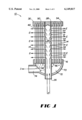
- FIG. 1 shows a membrane contactor, in partial cross-sectional view, according to a preferred form of the present invention.
- FIG. 2 shows a membrane contactor, in partial cross-sectional view, according to another preferred form of the present invention.
- FIG. 3 shows a membrane contactor, in partial cross-sectional view, according to another preferred form of the present invention.
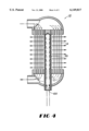
- FIG. 4 shows a membrane contactor, in partial cross-sectional view, and including a filter element, according to another preferred form of the present invention.
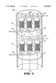
- FIG. 5 shows a multi-stage assembly according to a preferred form of the present invention.
- FIGS. 1-4 show example embodiments of a shell-less membrane contactor 10 according to preferred forms of the present invention.
- the membrane contactor 10 generally comprises a fluid distribution element 12, at least one hollow fiber membrane 14, and a barrier 16.
- a fluid distribution element 12 generally comprises a fluid distribution element 12, at least one hollow fiber membrane 14, and a barrier 16.
- the fluid distribution element of the present invention comprises a substantially rigid fluid distribution tube 20 having a wall defining an external surface 22 and an internal passage 24.
- the fluid distribution tube 20 is preferably a generally cylindrical element fabricated from plastics, polyolefins, polypropylene, metals, or other material(s) that are inert, or non-reactive with the materials in the fluid streams or contaminants intended to be processed.
- the fluid distribution tube 20 can comprise a tube of generally square or otherwise shaped cross-section.
- a first end 26 of the fluid distribution tube 20 is open to form an inlet for receiving a shell-side fluid E from an external source, and communicates the shell-side fluid E to the internal passage 24.
- the first end 26 can be provided with threads or other couplings for attachment to piping or tubing associated with the external source.
- a second end 28 of the fluid distribution tube 20, generally opposite the first end 26 is preferably closed to flow of the shell-side fluid E.
- the second end 28 is closed by mounting a support member 30 on or adjacent the second end 28.
- the second end 28 may be closed by forming the fluid distribution tube 20 as a closed cylinder, by deforming the fluid distribution tube 20, by means of a plug, or by other closure means.
- the fluid distribution tube 20 preferably includes a perforated wall section 32, comprising one or more discharge openings or outlets 34 for discharging the shell-side fluid E from the internal passage 24.
- a plurality of discharge openings 34 are provided generally evenly distributed over the perforated wall section 32.
- the discharge openings 34 preferably extend generally radially outwardly from the internal passage 24 to the external surface 22.
- One or more hollow fiber membranes 14 are also provided.
- a plurality of hollow fiber membranes 14 are provided, forming a fiber bundle 40.
- the fiber bundle 40 preferably generally surrounds at least a portion of the perforated wall section 32.
- the hollow fiber membranes 14 can take any of a number of forms, depending upon the desired application.
- the hollow fiber membranes 14 can be homogenous or asymmetric in terms of pore morphology, may or may not have a non-porous dense outside skin or a composite structure, and may or may not be permselective (having a higher permeability to one species or component than to another) to any of the process fluid components.
- hollow fiber membranes examples include permselective fiber membranes commercially available from Celgard, LLC, of Charlotte, N.C. under the name of Celgard Hollow Fiber Membranes; from Dainippon Ink and Chemicals, Inc. of Japan; or from Akzo-Nobel, of the Netherlands.
- Each hollow fiber membrane 14 preferably comprises a microporous wall having a multiplicity of micropores therethrough, an internal surface defining an internal lumen, and an external surface.
- Each hollow fiber membrane 14 has a first end 44 extending through and having its external surface in sealing contact with the barrier 16, whereby the barrier functions as a tube sheet.
- the first ends 44 are preferably cut off or otherwise terminate approximately flush with an outer surface 46 of the tube sheet 16, the outer surface 46 lying opposite the tube sheet from the perforated wall section 32 of the fluid distribution tube 20.
- the open first ends 44 form ports communicating a lumen-side fluid I to and/or from the lumens of the hollow fiber membranes 14.
- the tube sheet 16 is preferably formed from a polymeric potting resin (as used herein, a "polymeric" potting resin refers to any thermoplastic or thermoset potting resin).
- the tube sheet 16 is preferably formed around or otherwise mounted in sealing engagement with the external surface 22 of the fluid distribution tube 20, between the first end 26 and the perforated wall section 32.
- Example materials and methods of construction of the various components of the present invention not specifically described herein will be readily apparent to those skilled in the art. The reader is also directed to U.S. Pat. No. 4,220,535 to Leonard; U.S. Pat. No. 5,284,584 to Huang et al.; and U.S. Pat. No. 5,352,361 Prasad et al., all of which are incorporated herein by reference in their entireties, for additional background information regarding materials and methods of construction applicable to the present invention.
- Second ends 50 of the hollow fiber membranes 14 are preferably supported by a support member 30 mounted adjacent the second end 28 of the fluid distribution tube 20.
- the hollow fiber membranes 14 are maintained in an extended configuration, with their first ends sealingly engaged by the tube sheet 16 and their second ends sealingly engaged by the support member 30, and with at least a portion of their external surfaces between the tube sheet 16 and the support member 30 exposed to contact with shell-side fluid E discharged from the perforated wall section 32 of the fluid distribution tube 20.
- the support member 30 can take the form of a closure block 54, serving to close the second end 28 of the fluid distribution tube 20 against passage of shell-side fluid E, and serving to encapsulate or otherwise close the second ends 50 of the hollow fiber membranes 14 to prevent passage of lumen-side fluid I.
- the closure block is preferably formed from a polymeric potting resin similar to the material of the tube sheet 16.
- the support member 30 can comprise a second tube sheet 56.
- the second tube sheet 56 sealingly engages the external surfaces of the second ends 50 of the hollow fiber membranes 14.
- the second ends 50 extend through the second tube sheet 56, and are preferably cut off or otherwise terminated approximately flush with an outer surface 58 of the second tube sheet 56, the outer surface 58 lying opposite the second tube sheet 56 from the perforated wall section 32 of the fluid distribution tube 20.
- the open second ends 50 form second ports communicating a lumen-side fluid I to and/or from the lumens of the hollow fiber membranes 14.
- the lumen-side fluid I can traverse the contactor 10 through the lumens of the hollow fiber membranes 14, entering at one of the first or second ports and discharging from the other.
- the first and second tube sheets 16, 56 segregate the lumen-side fluid I from the shell-side fluid E.
- the second tube sheet 56 is preferably formed in substantially the same manner as the first tube sheet 16, from a polymeric potting resin.
- the second tube sheet 56 is preferably formed around or otherwise mounted in sealing engagement with the external surface 22 of the fluid distribution tube 20, adjacent its second end 28.
- the fluid contactor 10 of the present invention can optionally also comprise one or more end caps.
- a first end cap 70 can be provided in sealing engagement with the first tube sheet 16, to form a first chamber 72, open to fluid communication with the first ports of the hollow fiber membranes 14.
- the first end cap 70 may be a generally hemispherical or other hollow casing having a rim surface in connection with the outer periphery of the outer surface 46 of the first tube sheet 16.
- the first end cap 70 preferably comprises a first lumen-side fluid port 74 for receiving and/or discharging a flow of lumen-side fluid I.
- the first lumen-side fluid port 74 can be provided with threads or other couplings or fittings for attachment to an external fluid system.
- the first end 26 of the fluid distribution tube 20 extends through the first chamber 72, to provide a shell-side fluid port external of the first end cap 70.
- the first end 26 of the fluid distribution tube 20 can be provided with threads or other couplings or fittings for attachment to an external fluid system.
- the first end cap 70 can be integrally formed with the fluid distribution tube 20 as a unitary element, or the two can be formed as separate elements and joined or sealed to prevent the passage of fluid therebetween.
- the fluid contactor 10 of the present invention can optionally further comprise a second end cap 80.
- the second end cap 80 is preferably provided in sealing engagement with the second tube sheet 56, to form a second chamber 82, open to fluid communication with the second ports of the hollow fiber membranes 14.
- the second end cap 80 may be substantially similar or identical to the first end cap 70, comprising a generally hemispherical or other hollow casing having a rim surface in fluid-tight connection with the outer periphery of the outer surface 58 of the second tube sheet 56.
- the second end cap 80 preferably comprises a second lumen-side fluid port 84 for receiving and/or discharging a flow of lumen-side fluid I.
- the second lumen-side fluid port 84 can be provided with threads or other couplings or fittings for attachment to an external fluid system. It will be understood that embodiments of the present invention incorporating a closure block as the support member 30, such as the embodiment depicted in FIG. 1, will typically not require the provision of a second end cap 80, as the hollow fiber membranes 14 do not extend through the closure block to present ports allowing communication of lumen-side fluid into a second chamber 82.
- the fluid contactor 10 of the present invention can also comprise a removable and replaceable contactor cartridge for insertion in an external fluid delivery system incorporating endcaps or other components for fluid delivery to the fluid contactor 10.
- the fluid contactor 10 according to this embodiment of the present invention does not include first or second end caps 70, 80.
- sealing elements 90 such as O-rings or gaskets, can be provided between the tube sheet(s) 16, 56 and the cooperating components of the external housing, and between the first end 26 of the fluid distribution tube 20 and the cooperating components of the external housing.
- the sealing elements prevent loss of the lumen-side fluid I and the shell-side fluid E from the points of engagement between the fluid contactor 10 and the external housing, and maintain separation of the lumen-side fluid I from the shell-side fluid E.
- Clamps or other attachment means 92 can be provided for connecting the fluid contactor 10 to the external housing.
- the fluid contactor 10 of the present invention can optionally also include a bag filter 100, or other filter means, mounted within the internal passage 24 of the fluid distribution tube 20.
- the bag filter 100 is preferably fabricated from an inert material, which is unreactive with the particular fluids or contaminants likely to be encountered during intended use.
- the bag filter 100 may or may not be removable for repair or replacement.
- the filter 100 assists in removal of particulate matter from the shell-side fluid E, which otherwise could clog the fiber bundle 40 and reduce the efficiency of the contactor 10.
- the particulate size rating of the filter 100 is preferably selected depending upon the closeness of packing of the hollow fiber membranes 14 in the fiber bundle 40.
- the filter 100 is not removable (i.e., permanently attached within the internal passage 24 of the fluid distribution tube 20), the filter can be "back-flushed” periodically by reversing the flow direction within the fluid distribution tube 20 to dislodge and remove captured particles. If the filter 100 is removable, it can be periodically replaced or removed for cleaning.
- the fluid contactor 10 of the present invention advantageously eliminates the need for a surrounding shell, and is therefore designated a "shell-less" fluid contactor. Elimination of a surrounding shell reduces weight and expense, and results in minimal pressure drop across the contactor.
- Structural support for the contactor 10 is primarily provided by the fluid distribution tube 20, which retains the barrier or first tube sheet 16 and the support member 30 in their intended configurations. Larger diameter fluid contactors may require additional support, which can be provided through the provision of one or more support rods (unshown) extending between the barrier or first tube sheet 16 and the support member 30.
- the hollow fiber membranes 14 are generally exposed to the ambient surroundings between the barrier or first tube sheet 16 and the support member 30.
- the present invention also includes the provision of a multi-stage contactor assembly 105 for fluid processing.
- the assembly 105 preferably includes at least two stages, each stage comprising one or more fluid contactors 110.
- the assembly will be described with reference to the depicted two-stage contactor assembly 105, comprising a first stage 112 and a second stage 114. It will be understood that additional stages can be added to the system in substantially like manner, depending upon the desired system characteristics.
- At least one, and preferably all of the contactors 110 included in the assembly 105 comprise shell-less fluid contactors substantially as described above.
- Each stage 112, 114 preferably comprises a support base 116, 118, upon which the contactors 110 of the respective stages are mounted.
- Each support base 116, 118 can comprise, for example, a substantially rigid sheet or plate formed from an inert material. Each support base 116, 118 can be provided with one or more openings to accommodate passage of fluid conduits communicating lumen-side fluid and/or shell-side fluid to the contactors 110. The support bases 116, 118 can also serve as barriers to fluid passage between adjacent stages of the assembly 105, permitting fluid flow from one stage to the next only through the contactors 110.
- the assembly 105 preferably further comprises collection and transfer means for collecting the shell-side fluid E discharged from one stage, and transferring the collected shell-side fluid E to the second stage.
- the collection and transfer means comprises the wall(s) 120 of a portion of a stack, discharge pipe or other conduit for an effluent process stream.
- the collection and transfer means can comprise any fluid-tight enclosure surrounding one or more stages of the assembly.
- Inlet manifolds 122 and outlet manifolds 124 for the lumen-side fluid I can be provided.
- the inlet manifolds 122 communicate fluid from an external source into the first lumen-side fluid ports 74 of each contactor 110, and the outlet manifolds 122 communicate fluid from the second lumen-side fluid ports 84 of each contactor 110 to an outlet.
- the fluid contactor 10 of the present invention enables a process for transferring one or more fluid components between a shell-side fluid E and a lumen-side fluid I.
- the shell-side fluid E is introduced into the fluid distribution element of the shell-less fluid contactor from an external source.
- the shell-side fluid E enters the first end 26 of the fluid distribution tube 20, and passes into the internal passage 24.
- the lumen-side fluid I is introduced into a lumen of at least one hollow fiber membrane external of the fluid distribution element.
- the lumen-side fluid I enters through the first and/or the second lumen-side fluid port 74, 84.
- the lumen-side fluid I is communicated through a lumen-side fluid port 74, 84, into the first and/or the second chamber 72, 82 within the respective endcap 70, 80, and is introduced into the lumens of the hollow fiber membranes through the first and/or second port of the hollow fiber membranes.
- the shell-side fluid E and the lumen-side fluid I can flow in generally opposite directions (counter-current flow).
- the shell-side fluid E and the lumen-side fluid I can flow in generally the same direction (parallel flow).
- the shell-side fluid E is discharged from the fluid distribution element into contact with the external surface(s) of the at least one hollow fiber membrane to effect a transfer of a fluid component between the shell-side fluid and the lumen-side fluid.
- the shell-side fluid E is discharged from the openings or outlets 34 of the perforated wall section 32 into contact with the external surface(s) of the at least one hollow fiber membrane. Diffusion of one or more fluid components occurs across the microporous walls of the hollow fiber membranes, thereby providing a transfer of the component(s) between the shell-side fluid E and the lumen-side fluid I.
- the hollow fiber membranes 14 are selected for particular applications to prevent a fluid flow across the hollow fiber wall, thereby limiting transfer to diffusion across the hollow fiber wall, and enabling selective control of the transferred component(s).
- the driving force for the diffusion across the hollow fiber wall preferably is provided by a difference in concentration, partial pressure or, more generally, chemical potential, of the transferring component(s) between the shell-side fluid E and the lumen-side fluid I.
- the transfer can be selectively controlled by appropriate selection of the shell-side fluid E, the lumen-side fluid I, the material and thickness of the hollow fiber membrane, and/or the pressures or other conditions or characteristics of the fluids.
- the fluid component is transferred from the shell-side fluid E to the lumen-side fluid I.
- the fluid component can be transferred from the lumen-side fluid I to the shell-side fluid E.
- the shell-side fluid E is preferably discharged from the fluid distribution tube 20 generally radially outwardly from a plurality of generally radial openings 34 extending from the internal passage 24 through the wall of the fluid distribution tube 20.
- the at least one hollow fiber membrane preferably comprises a plurality of hollow fiber membranes 14 forming a fiber bundle surrounding the plurality of generally radial openings 34.
- the shell-side fluid E preferably is distributed generally radially outwardly through the interstices between the plurality of hollow fiber membranes 14.
- the shell-side fluid E can be collected from the shell-less fluid contactor after contacting the external surface(s) of the at least one hollow fiber membrane to effect the transfer of the component(s) between the shell-side fluid E and the lumen-side fluid I. As discussed above with reference to FIG. 5, the collected shell-side fluid E can then be transferred to a second, and possibly further additional stages of fluid contactors for further processing, as desired.
- One example application of the present invention provides for degassing of water or other liquids through the application of a partial vacuum (i.e., a negative pressure differential) to the lumens of the hollow fiber membranes.
- a partial vacuum i.e., a negative pressure differential
- This application can be practiced using a fluid contactor having hollow fiber membranes open at a first end thereof, and closed at a second end, such as by a closure block as shown in FIG. 1, by applying vacuum to the single lumen-side fluid port.
- this application can be practiced using a fluid contactor having hollow fiber membranes open at both ends, as shown in FIGS. 2-4, by applying vacuum to both lumen-side fluid ports, or by blocking one lumen-side fluid port and applying vacuum to the other.
- Water or other liquid to be degassed enters the contactor as the shell-side fluid through the first end of the fluid distribution tube, and is discharged outwardly from the perforated wall section into contact with the fiber bed.
- the contactor can be submerged in a plenum from which water is continuously discharged, or a plurality of contactors can be installed in a single container.
- the hollow fibers are preferably hydrophobic, or have a gas-permeable dense skin on their external surfaces, thereby preventing water transfer across the wall of the hollow fibers.
- An external vacuum source applies a vacuum to the lumens of the hollow fibers. Dissolved gasses are stripped from the liquid, diffusing across the fiber walls and into the lumens of the hollow fibers.
- the gasses are removed from the lumens through the lumen-side fluid ports, and can be discharged to the atmosphere, or collected.
- the degassed liquid exits the contactor through the fiber bundle, and can be collected, and optionally can be transferred to additional stages for further processing.
- Another example application of the present invention provides transfer of a fluid component from the shell-side fluid to a lumen-side sweep gas.
- This application is preferably practiced using a fluid contactor having hollow fiber membranes open at both ends, as shown in FIGS. 2-4, by introducing the lumen-side sweep gas into one lumen-side fluid port and discharging the lumen-side sweep gas from the other lumen-side fluid port.
- vacuum can be simultaneously applied to the discharge port.
- End caps can be provided at either or both ends of the contactor, as desired.
- the transferred component diffuses through the wall of the hollow fiber membrane from the shell-side fluid into the lumen-side sweep gas.
- the sweep gas is thereby enriched with the transferred component, and the shell-side fluid is depleted of the transferred component.
- This method of application can be coupled with the method of Example 1 above.
- water can be first degassed by vacuum according to Example 1, to remove a substantial portion of dissolved gasses, including oxygen.
- the degassed water discharged from the vacuum contactor of Example 1 is then collected and transferred to a sweep gas contactor.
- the level of dissolved oxygen in the water is further reduced by diffusion into a sweep gas, such as nitrogen, in the sweep gas contactor.
- the fluid contactor of the present invention can be used to process a gas or waste air stream, prior to discharge to the atmosphere, by removal and transfer of toxic or harmful components from the gas stream into a suitable liquid absorbent.
- This application is preferably practiced using a fluid contactor having hollow fiber membranes open at both ends, as shown in FIGS. 2-4.
- the gas stream to be processed is introduced as the shell-side fluid through the fluid distribution tube and flows radially outward and transversely over the fiber bed before being discharged directly into the atmosphere.
- a suitable liquid absorbent is provided as the lumen-side fluid.
- the liquid absorbent is prevented from entering the pores of the hollow fiber wall either by the surface exclusion property of the fine pores or due to the presence of a highly gas-permeable, thin, dense skin on the inside surface of the fiber wall. Toxic or harmful components from the gas stream diffuse through the wall of the hollow fiber membranes, from the gas stream into the liquid absorbent.
- the fluid contactor of the present invention can be used to extract organic contaminants or pollutants from aqueous streams, such as waste streams, prior to discharge to the environment or recycle use.
- a fluid contactor having hollow fiber membranes open at both ends, as shown in FIGS. 2-4.
- the lumen-side fluid is any suitable non-toxic organic solvent which serves as an extractant to selectively remove the target organic contaminants from water or aqueous fluids.
- the aqueous stream is the shell-side fluid. Organic contaminants or pollutants diffuse through the wall of the hollow fiber membranes, from the water or aqueous fluid into the organic extractant.
- the fluid contactor of the present invention can be used to extract dissolved inorganic salt impurities from an organic solvent. This can be achieved by contacting the organic solvent, through the walls of the hollow fiber membranes, with water or other aqueous material, which selectively leaches the salt from the solvent.
- This application is preferably practiced using a fluid contactor having hollow fiber membranes open at both ends, as shown in FIGS. 2-4.
- the organic liquid to be processed serves as the shell-side fluid
- the wash water or other aqueous material serves as the lumen-side fluid.
- Inorganic salt impurities diffuse through the wall of the hollow fiber membranes, from the organic liquid into the wash water or other aqueous material.
Abstract
Description
Claims (20)
Priority Applications (5)
| Application Number | Priority Date | Filing Date | Title |
|---|---|---|---|
| US09/265,064 US6149817A (en) | 1999-03-08 | 1999-03-08 | Shell-less hollow fiber membrane fluid contactor |
| CA002298393A CA2298393C (en) | 1999-03-08 | 2000-02-14 | Shell-less hollow fiber membrane fluid contactor |
| DE60037356T DE60037356T2 (en) | 1999-03-08 | 2000-03-01 | Caseless Hollow Fiber Membrane Device |
| EP00103489A EP1034834B1 (en) | 1999-03-08 | 2000-03-01 | Shell-less h?llow fiber membrane fluid contactor |
| JP2000063421A JP4593719B2 (en) | 1999-03-08 | 2000-03-08 | Shellless hollow fiber membrane fluid contactor |
Applications Claiming Priority (1)
| Application Number | Priority Date | Filing Date | Title |
|---|---|---|---|
| US09/265,064 US6149817A (en) | 1999-03-08 | 1999-03-08 | Shell-less hollow fiber membrane fluid contactor |
Publications (1)
| Publication Number | Publication Date |
|---|---|
| US6149817A true US6149817A (en) | 2000-11-21 |
Family
ID=23008809
Family Applications (1)
| Application Number | Title | Priority Date | Filing Date |
|---|---|---|---|
| US09/265,064 Expired - Lifetime US6149817A (en) | 1999-03-08 | 1999-03-08 | Shell-less hollow fiber membrane fluid contactor |
Country Status (5)
| Country | Link |
|---|---|
| US (1) | US6149817A (en) |
| EP (1) | EP1034834B1 (en) |
| JP (1) | JP4593719B2 (en) |
| CA (1) | CA2298393C (en) |
| DE (1) | DE60037356T2 (en) |
Cited By (63)
| Publication number | Priority date | Publication date | Assignee | Title |
|---|---|---|---|---|
| US20040045893A1 (en) * | 2000-07-10 | 2004-03-11 | Akihiro Watanabe | Hollow thread film cartridge, hollow thread film module using the cartridge, and tank type filter |
| US20050284293A1 (en) * | 2002-12-19 | 2005-12-29 | Rubas Paul J | Membrane module for separation of fluids |
| US20060151375A1 (en) * | 2003-08-05 | 2006-07-13 | Katsushige Marui | Hollow fiber membrane submodule and module including the same |
| US20060191838A1 (en) * | 1999-12-17 | 2006-08-31 | Millipore Corporation | Spiral wound hollow fiber potting |
| US20070185527A1 (en) * | 2005-10-18 | 2007-08-09 | Ab Ortho, Llc | Apparatus and method for treating soft tissue injuries |
| US20090017541A1 (en) * | 2004-08-17 | 2009-01-15 | Kyushu Institute Of Technology | Porous Sheet-Form Material For Cell Culture, And Bioreactor And Culturing Method Utilizing Same |
| US7591950B2 (en) * | 2004-11-02 | 2009-09-22 | Siemens Water Technologies Corp. | Submerged cross-flow filtration |
| US20090272684A1 (en) * | 2008-04-30 | 2009-11-05 | Celgard Llc | Contained liquid membrane contactor and a method of manufacturing the same |
| US20090321332A1 (en) * | 2006-07-26 | 2009-12-31 | Vlaamse Instelliing Voor Technologisch Onderzoek N .V. (VITO) | Capillary membrane filtration module |
| US7718057B2 (en) | 2005-10-05 | 2010-05-18 | Siemens Water Technologies Corp. | Wastewater treatment system |
| US7718065B2 (en) | 2004-04-22 | 2010-05-18 | Siemens Water Technologies Corp. | Filtration method and apparatus |
| EP2211233A2 (en) | 2003-07-21 | 2010-07-28 | Entegris, Inc. | Lithographic projection apparatus and gas purging method |
| US20100230366A1 (en) * | 2008-09-25 | 2010-09-16 | Otv Sa | Seawater treatment method for the production of injection water for undersea oil drilling and corresponding installation |
| US7862719B2 (en) | 2004-08-20 | 2011-01-04 | Siemens Water Technologies Corp. | Square membrane manifold system |
| US7931463B2 (en) | 2001-04-04 | 2011-04-26 | Siemens Water Technologies Corp. | Apparatus for potting membranes |
| US7938966B2 (en) | 2002-10-10 | 2011-05-10 | Siemens Water Technologies Corp. | Backwash method |
| EP2361660A1 (en) * | 2003-11-05 | 2011-08-31 | Rheodyne, LLC | Axial transfer line degassing |
| US8048306B2 (en) | 1996-12-20 | 2011-11-01 | Siemens Industry, Inc. | Scouring method |
| US8182687B2 (en) | 2002-06-18 | 2012-05-22 | Siemens Industry, Inc. | Methods of minimising the effect of integrity loss in hollow fibre membrane modules |
| US8268176B2 (en) | 2003-08-29 | 2012-09-18 | Siemens Industry, Inc. | Backwash |
| US8287743B2 (en) | 2007-05-29 | 2012-10-16 | Siemens Industry, Inc. | Membrane cleaning with pulsed airlift pump |
| US8293098B2 (en) | 2006-10-24 | 2012-10-23 | Siemens Industry, Inc. | Infiltration/inflow control for membrane bioreactor |
| US8318028B2 (en) | 2007-04-02 | 2012-11-27 | Siemens Industry, Inc. | Infiltration/inflow control for membrane bioreactor |
| US20130020250A1 (en) * | 2011-07-18 | 2013-01-24 | Fresenius Medical Care Duetschland Gmbh | Filter module |
| US8372282B2 (en) | 2002-12-05 | 2013-02-12 | Siemens Industry, Inc. | Mixing chamber |
| US8377305B2 (en) | 2004-09-15 | 2013-02-19 | Siemens Industry, Inc. | Continuously variable aeration |
| US8382981B2 (en) | 2008-07-24 | 2013-02-26 | Siemens Industry, Inc. | Frame system for membrane filtration modules |
| US8496828B2 (en) | 2004-12-24 | 2013-07-30 | Siemens Industry, Inc. | Cleaning in membrane filtration systems |
| US8506806B2 (en) | 2004-09-14 | 2013-08-13 | Siemens Industry, Inc. | Methods and apparatus for removing solids from a membrane module |
| US8512568B2 (en) | 2001-08-09 | 2013-08-20 | Siemens Industry, Inc. | Method of cleaning membrane modules |
| US8652331B2 (en) | 2008-08-20 | 2014-02-18 | Siemens Water Technologies Llc | Membrane system backwash energy efficiency |
| US8758621B2 (en) | 2004-03-26 | 2014-06-24 | Evoqua Water Technologies Llc | Process and apparatus for purifying impure water using microfiltration or ultrafiltration in combination with reverse osmosis |
| US8758622B2 (en) | 2004-12-24 | 2014-06-24 | Evoqua Water Technologies Llc | Simple gas scouring method and apparatus |
| US8790515B2 (en) | 2004-09-07 | 2014-07-29 | Evoqua Water Technologies Llc | Reduction of backwash liquid waste |
| US8808540B2 (en) | 2003-11-14 | 2014-08-19 | Evoqua Water Technologies Llc | Module cleaning method |
| US8858796B2 (en) | 2005-08-22 | 2014-10-14 | Evoqua Water Technologies Llc | Assembly for water filtration using a tube manifold to minimise backwash |
| US8956464B2 (en) | 2009-06-11 | 2015-02-17 | Evoqua Water Technologies Llc | Method of cleaning membranes |
| US9022224B2 (en) | 2010-09-24 | 2015-05-05 | Evoqua Water Technologies Llc | Fluid control manifold for membrane filtration system |
| US20150343330A1 (en) * | 2014-05-28 | 2015-12-03 | Chemetics Inc. | Membrane separation at high temperature differential |
| US9339768B2 (en) | 2013-08-23 | 2016-05-17 | 3M Innovative Properties Company | Multi-cartridge membrane contactors, modules, systems, and related methods |
| WO2016209755A1 (en) * | 2015-06-22 | 2016-12-29 | 3M Innovative Properties Company | Compact cross-flow contactor |
| US9533261B2 (en) | 2012-06-28 | 2017-01-03 | Evoqua Water Technologies Llc | Potting method |
| US9604166B2 (en) | 2011-09-30 | 2017-03-28 | Evoqua Water Technologies Llc | Manifold arrangement |
| US9675938B2 (en) | 2005-04-29 | 2017-06-13 | Evoqua Water Technologies Llc | Chemical clean for membrane filter |
| US9764288B2 (en) | 2007-04-04 | 2017-09-19 | Evoqua Water Technologies Llc | Membrane module protection |
| US9764289B2 (en) | 2012-09-26 | 2017-09-19 | Evoqua Water Technologies Llc | Membrane securement device |
| US9815027B2 (en) | 2012-09-27 | 2017-11-14 | Evoqua Water Technologies Llc | Gas scouring apparatus for immersed membranes |
| US9914097B2 (en) | 2010-04-30 | 2018-03-13 | Evoqua Water Technologies Llc | Fluid flow distribution device |
| US9925499B2 (en) | 2011-09-30 | 2018-03-27 | Evoqua Water Technologies Llc | Isolation valve with seal for end cap of a filtration system |
| US9962865B2 (en) | 2012-09-26 | 2018-05-08 | Evoqua Water Technologies Llc | Membrane potting methods |
| US10322375B2 (en) | 2015-07-14 | 2019-06-18 | Evoqua Water Technologies Llc | Aeration device for filtration system |
| US10369515B2 (en) * | 2010-11-04 | 2019-08-06 | Ube Industries, Ltd. | Gas separation membrane module and method for gas separation |
| US10369263B2 (en) | 2014-03-29 | 2019-08-06 | Novaflux Inc. | Blood processing cartridges and systems, and methods for extracorporeal blood therapies |
| US10399040B2 (en) | 2015-09-24 | 2019-09-03 | Novaflux Inc. | Cartridges and systems for membrane-based therapies |
| WO2019178281A1 (en) * | 2018-03-15 | 2019-09-19 | Biotherm Hydronic, Inc. | Modular devices and systems for infusing gas into a liquid and methods of manufacture and use thereof |
| US10427102B2 (en) | 2013-10-02 | 2019-10-01 | Evoqua Water Technologies Llc | Method and device for repairing a membrane filtration module |
| US10426884B2 (en) | 2015-06-26 | 2019-10-01 | Novaflux Inc. | Cartridges and systems for outside-in flow in membrane-based therapies |
| US20190329158A1 (en) * | 2018-04-25 | 2019-10-31 | Hamilton Sundstrand Corporation | Oxygen removal unit with tortuous path |
| US11045747B2 (en) | 2016-08-17 | 2021-06-29 | Mitsubishi Chemical Cleansui Corporation | Hollow fiber membrane module, degassing and gas supplying device, inkjet printer, and device for manufacturing carbonated spring |
| CN113226507A (en) * | 2018-12-28 | 2021-08-06 | Dic株式会社 | Degassing system, method for degassing liquid, degassing unit, degassing module, method for manufacturing degassing system, and method for producing natural resource |
| EP3858452A4 (en) * | 2018-09-27 | 2022-05-11 | DIC Corporation | Degasification system, liquid degasification method, degasification module, method for manufacturing degasification system, and method for producing natural resources |
| US11331629B2 (en) * | 2019-06-03 | 2022-05-17 | Hamilton Sundstrand Corporation | Modular liquid degassing systems |
| US11944934B2 (en) | 2021-12-22 | 2024-04-02 | Mojave Energy Systems, Inc. | Electrochemically regenerated liquid desiccant dehumidification system using a secondary heat pump |
Families Citing this family (8)
| Publication number | Priority date | Publication date | Assignee | Title |
|---|---|---|---|---|
| US6402818B1 (en) * | 2000-06-02 | 2002-06-11 | Celgard Inc. | Degassing a liquid with a membrane contactor |
| WO2009012597A1 (en) * | 2007-07-26 | 2009-01-29 | Fpinnovations | Process for treating pulp mill condensates using a hollow fiber contactor |
| EP2055368A1 (en) | 2007-10-30 | 2009-05-06 | Membrana GmbH | Shell-less hollow fibre module |
| US8945276B2 (en) | 2013-06-07 | 2015-02-03 | Membrane Technology And Research, Inc. | Parallel feed gas separation membrane element assembly |
| DE102013108709A1 (en) * | 2013-08-12 | 2015-02-12 | Bauer-Verfahrenstechnik-GmbH | Device for degassing a fluid |
| WO2016143920A1 (en) * | 2015-03-09 | 2016-09-15 | 주식회사 세프라텍 | Separation membrane contactor module and membrane contact system and membrane contact method for purifying bio-gas using same |
| JP6615969B1 (en) | 2018-09-26 | 2019-12-04 | 日東電工株式会社 | Hollow fiber membrane module |
| CN115253598B (en) * | 2022-07-12 | 2023-04-28 | 青岛海湾化工设计研究院有限公司 | For CO 2 Trapped tower absorption membrane contactor |
Citations (15)
| Publication number | Priority date | Publication date | Assignee | Title |
|---|---|---|---|---|
| US4220535A (en) * | 1978-08-04 | 1980-09-02 | Monsanto Company | Multi-zoned hollow fiber permeator |
| US4622143A (en) * | 1985-07-02 | 1986-11-11 | E. I. Du Pont De Nemours And Company | Double-ended hollow fiber permeator |
| US4675109A (en) * | 1985-05-08 | 1987-06-23 | E. I. Du Pont De Nemours And Company | Reverse osmosis permeator |
| US4752305A (en) * | 1986-10-30 | 1988-06-21 | The Dow Chemical Company | Device and method for separating individual fluids from a mixture of fluids |
| US5137631A (en) * | 1991-10-22 | 1992-08-11 | E. I. Du Pont De Nemours And Company | Multiple bundle permeator |
| US5248424A (en) * | 1990-08-17 | 1993-09-28 | Zenon Environmental Inc. | Frameless array of hollow fiber membranes and method of maintaining clean fiber surfaces while filtering a substrate to withdraw a permeate |
| US5284584A (en) * | 1992-12-31 | 1994-02-08 | Hoechst Celanese Corporation | Hollow fiber membrane fabric - containing cartridges and modules having solvent-resistant thermoplastic tube sheets, and methods for making the same |
| US5352361A (en) * | 1991-12-31 | 1994-10-04 | Hoechst Celanese Corporation | Spiral-wound hollow fiber membrane fabric cartridges and modules having flow-directing baffles |
| US5470469A (en) * | 1994-09-16 | 1995-11-28 | E. I. Du Pont De Nemours And Company | Hollow fiber cartridge |
| US5607593A (en) * | 1993-11-30 | 1997-03-04 | Otv Omnium De Trajtements Et De Valorisation S.A. | Installation for making water potable with submerged filtering membranes |
| US5643455A (en) * | 1991-08-07 | 1997-07-01 | Memtel Limited | Concentration of solids in a suspension using hollow fibre membranes |
| US5783083A (en) * | 1995-08-11 | 1998-07-21 | Zenon Environmental Inc. | Vertical cylindrical skein of hollow fiber membranes and method of maintaining clean fiber surfaces |
| US5922201A (en) * | 1992-02-12 | 1999-07-13 | Mitsubishi Rayon Co., Ltd. | Hollow fiber membrane module |
| US5944997A (en) * | 1995-08-11 | 1999-08-31 | Zenon Environmental Inc. | System for maintaining a clean skein of hollow fibers while filtering suspended solids |
| US5958243A (en) * | 1996-07-11 | 1999-09-28 | Zenon Environmental Inc. | Apparatus and method for membrane filtration with enhanced net flux |
Family Cites Families (11)
| Publication number | Priority date | Publication date | Assignee | Title |
|---|---|---|---|---|
| JPS59207827A (en) * | 1983-05-10 | 1984-11-26 | Ube Ind Ltd | Method for separating gas from gas mixture |
| JPS60261508A (en) * | 1984-06-08 | 1985-12-24 | Ube Ind Ltd | Separating device for fluid |
| JPS61103520A (en) * | 1984-10-26 | 1986-05-22 | Asahi Glass Co Ltd | Operation of hollow yarn membrane module for production of oxygen-enriched air |
| JPS62160105A (en) * | 1986-01-08 | 1987-07-16 | Mitsubishi Rayon Eng Co Ltd | Cleaning method for hollow yarn filter module |
| US4871379A (en) * | 1987-12-22 | 1989-10-03 | E. I. Du Pont De Nemours And Company | Modular, shell-less, air permeator |
| US5013331A (en) * | 1989-06-30 | 1991-05-07 | E. I. Du Pont De Nemours And Company | Permeator with selectable flow rates |
| US5332498A (en) * | 1992-10-13 | 1994-07-26 | Transfair Corporation | Integrated hollow fiber membrane permeators and method of fabricating integrated permeators |
| JP3161654B2 (en) * | 1993-06-10 | 2001-04-25 | 宇部興産株式会社 | Hollow fiber membrane module and filtration device using the same |
| JPH0768103A (en) * | 1993-09-06 | 1995-03-14 | Toray Ind Inc | Membrane deaerating method |
| JPH0947762A (en) * | 1995-05-29 | 1997-02-18 | Toto Ltd | Membrane module for waste water treatment and waste water treatment device and waste water treatment using the same |
| JP3677858B2 (en) * | 1996-03-22 | 2005-08-03 | 栗田工業株式会社 | Membrane deaerator |
-
1999
- 1999-03-08 US US09/265,064 patent/US6149817A/en not_active Expired - Lifetime
-
2000
- 2000-02-14 CA CA002298393A patent/CA2298393C/en not_active Expired - Fee Related
- 2000-03-01 DE DE60037356T patent/DE60037356T2/en not_active Expired - Lifetime
- 2000-03-01 EP EP00103489A patent/EP1034834B1/en not_active Expired - Lifetime
- 2000-03-08 JP JP2000063421A patent/JP4593719B2/en not_active Expired - Fee Related
Patent Citations (15)
| Publication number | Priority date | Publication date | Assignee | Title |
|---|---|---|---|---|
| US4220535A (en) * | 1978-08-04 | 1980-09-02 | Monsanto Company | Multi-zoned hollow fiber permeator |
| US4675109A (en) * | 1985-05-08 | 1987-06-23 | E. I. Du Pont De Nemours And Company | Reverse osmosis permeator |
| US4622143A (en) * | 1985-07-02 | 1986-11-11 | E. I. Du Pont De Nemours And Company | Double-ended hollow fiber permeator |
| US4752305A (en) * | 1986-10-30 | 1988-06-21 | The Dow Chemical Company | Device and method for separating individual fluids from a mixture of fluids |
| US5248424A (en) * | 1990-08-17 | 1993-09-28 | Zenon Environmental Inc. | Frameless array of hollow fiber membranes and method of maintaining clean fiber surfaces while filtering a substrate to withdraw a permeate |
| US5643455A (en) * | 1991-08-07 | 1997-07-01 | Memtel Limited | Concentration of solids in a suspension using hollow fibre membranes |
| US5137631A (en) * | 1991-10-22 | 1992-08-11 | E. I. Du Pont De Nemours And Company | Multiple bundle permeator |
| US5352361A (en) * | 1991-12-31 | 1994-10-04 | Hoechst Celanese Corporation | Spiral-wound hollow fiber membrane fabric cartridges and modules having flow-directing baffles |
| US5922201A (en) * | 1992-02-12 | 1999-07-13 | Mitsubishi Rayon Co., Ltd. | Hollow fiber membrane module |
| US5284584A (en) * | 1992-12-31 | 1994-02-08 | Hoechst Celanese Corporation | Hollow fiber membrane fabric - containing cartridges and modules having solvent-resistant thermoplastic tube sheets, and methods for making the same |
| US5607593A (en) * | 1993-11-30 | 1997-03-04 | Otv Omnium De Trajtements Et De Valorisation S.A. | Installation for making water potable with submerged filtering membranes |
| US5470469A (en) * | 1994-09-16 | 1995-11-28 | E. I. Du Pont De Nemours And Company | Hollow fiber cartridge |
| US5783083A (en) * | 1995-08-11 | 1998-07-21 | Zenon Environmental Inc. | Vertical cylindrical skein of hollow fiber membranes and method of maintaining clean fiber surfaces |
| US5944997A (en) * | 1995-08-11 | 1999-08-31 | Zenon Environmental Inc. | System for maintaining a clean skein of hollow fibers while filtering suspended solids |
| US5958243A (en) * | 1996-07-11 | 1999-09-28 | Zenon Environmental Inc. | Apparatus and method for membrane filtration with enhanced net flux |
Cited By (95)
| Publication number | Priority date | Publication date | Assignee | Title |
|---|---|---|---|---|
| US8048306B2 (en) | 1996-12-20 | 2011-11-01 | Siemens Industry, Inc. | Scouring method |
| US20060191838A1 (en) * | 1999-12-17 | 2006-08-31 | Millipore Corporation | Spiral wound hollow fiber potting |
| US7083726B2 (en) * | 2000-07-10 | 2006-08-01 | Asahi Kasei Kabushiki Kaisha | Hollow thread film cartridge, hollow thread film module using the cartridge, and tank type filter |
| US20040045893A1 (en) * | 2000-07-10 | 2004-03-11 | Akihiro Watanabe | Hollow thread film cartridge, hollow thread film module using the cartridge, and tank type filter |
| US7931463B2 (en) | 2001-04-04 | 2011-04-26 | Siemens Water Technologies Corp. | Apparatus for potting membranes |
| US8518256B2 (en) | 2001-04-04 | 2013-08-27 | Siemens Industry, Inc. | Membrane module |
| US8512568B2 (en) | 2001-08-09 | 2013-08-20 | Siemens Industry, Inc. | Method of cleaning membrane modules |
| US8182687B2 (en) | 2002-06-18 | 2012-05-22 | Siemens Industry, Inc. | Methods of minimising the effect of integrity loss in hollow fibre membrane modules |
| US7938966B2 (en) | 2002-10-10 | 2011-05-10 | Siemens Water Technologies Corp. | Backwash method |
| US8372282B2 (en) | 2002-12-05 | 2013-02-12 | Siemens Industry, Inc. | Mixing chamber |
| US20050284293A1 (en) * | 2002-12-19 | 2005-12-29 | Rubas Paul J | Membrane module for separation of fluids |
| US7686868B2 (en) * | 2002-12-19 | 2010-03-30 | Exxonmobil Upstream Research Company | Membrane module for separation of fluids |
| EP2211233A2 (en) | 2003-07-21 | 2010-07-28 | Entegris, Inc. | Lithographic projection apparatus and gas purging method |
| US7635428B2 (en) | 2003-08-05 | 2009-12-22 | Toyo Boseki Kabushiki Kaisha | Hollow fiber membrane submodule and module including the same |
| US20060151375A1 (en) * | 2003-08-05 | 2006-07-13 | Katsushige Marui | Hollow fiber membrane submodule and module including the same |
| US8268176B2 (en) | 2003-08-29 | 2012-09-18 | Siemens Industry, Inc. | Backwash |
| EP2361660A1 (en) * | 2003-11-05 | 2011-08-31 | Rheodyne, LLC | Axial transfer line degassing |
| US8808540B2 (en) | 2003-11-14 | 2014-08-19 | Evoqua Water Technologies Llc | Module cleaning method |
| US8758621B2 (en) | 2004-03-26 | 2014-06-24 | Evoqua Water Technologies Llc | Process and apparatus for purifying impure water using microfiltration or ultrafiltration in combination with reverse osmosis |
| US7718065B2 (en) | 2004-04-22 | 2010-05-18 | Siemens Water Technologies Corp. | Filtration method and apparatus |
| US8435781B2 (en) * | 2004-08-17 | 2013-05-07 | Kyushu Institute Of Technology | Porous sheet-form material for cell culture, and bioreactor and culturing method utilizing same |
| US20090017541A1 (en) * | 2004-08-17 | 2009-01-15 | Kyushu Institute Of Technology | Porous Sheet-Form Material For Cell Culture, And Bioreactor And Culturing Method Utilizing Same |
| US7862719B2 (en) | 2004-08-20 | 2011-01-04 | Siemens Water Technologies Corp. | Square membrane manifold system |
| US8790515B2 (en) | 2004-09-07 | 2014-07-29 | Evoqua Water Technologies Llc | Reduction of backwash liquid waste |
| US8506806B2 (en) | 2004-09-14 | 2013-08-13 | Siemens Industry, Inc. | Methods and apparatus for removing solids from a membrane module |
| US8377305B2 (en) | 2004-09-15 | 2013-02-19 | Siemens Industry, Inc. | Continuously variable aeration |
| US7591950B2 (en) * | 2004-11-02 | 2009-09-22 | Siemens Water Technologies Corp. | Submerged cross-flow filtration |
| US8496828B2 (en) | 2004-12-24 | 2013-07-30 | Siemens Industry, Inc. | Cleaning in membrane filtration systems |
| US8758622B2 (en) | 2004-12-24 | 2014-06-24 | Evoqua Water Technologies Llc | Simple gas scouring method and apparatus |
| US9675938B2 (en) | 2005-04-29 | 2017-06-13 | Evoqua Water Technologies Llc | Chemical clean for membrane filter |
| US8894858B1 (en) | 2005-08-22 | 2014-11-25 | Evoqua Water Technologies Llc | Method and assembly for water filtration using a tube manifold to minimize backwash |
| US8858796B2 (en) | 2005-08-22 | 2014-10-14 | Evoqua Water Technologies Llc | Assembly for water filtration using a tube manifold to minimise backwash |
| US7718057B2 (en) | 2005-10-05 | 2010-05-18 | Siemens Water Technologies Corp. | Wastewater treatment system |
| US7722769B2 (en) | 2005-10-05 | 2010-05-25 | Siemens Water Technologies Corp. | Method for treating wastewater |
| US20070185527A1 (en) * | 2005-10-18 | 2007-08-09 | Ab Ortho, Llc | Apparatus and method for treating soft tissue injuries |
| US20090321332A1 (en) * | 2006-07-26 | 2009-12-31 | Vlaamse Instelliing Voor Technologisch Onderzoek N .V. (VITO) | Capillary membrane filtration module |
| US8293098B2 (en) | 2006-10-24 | 2012-10-23 | Siemens Industry, Inc. | Infiltration/inflow control for membrane bioreactor |
| US8623202B2 (en) | 2007-04-02 | 2014-01-07 | Siemens Water Technologies Llc | Infiltration/inflow control for membrane bioreactor |
| US8318028B2 (en) | 2007-04-02 | 2012-11-27 | Siemens Industry, Inc. | Infiltration/inflow control for membrane bioreactor |
| US9764288B2 (en) | 2007-04-04 | 2017-09-19 | Evoqua Water Technologies Llc | Membrane module protection |
| US8287743B2 (en) | 2007-05-29 | 2012-10-16 | Siemens Industry, Inc. | Membrane cleaning with pulsed airlift pump |
| US8622222B2 (en) | 2007-05-29 | 2014-01-07 | Siemens Water Technologies Llc | Membrane cleaning with pulsed airlift pump |
| US9206057B2 (en) | 2007-05-29 | 2015-12-08 | Evoqua Water Technologies Llc | Membrane cleaning with pulsed airlift pump |
| US10507431B2 (en) | 2007-05-29 | 2019-12-17 | Evoqua Water Technologies Llc | Membrane cleaning with pulsed airlift pump |
| US8372276B2 (en) | 2007-05-29 | 2013-02-12 | Siemens Industry, Inc. | Membrane cleaning with pulsed airlift pump |
| US8840783B2 (en) | 2007-05-29 | 2014-09-23 | Evoqua Water Technologies Llc | Water treatment membrane cleaning with pulsed airlift pump |
| US9573824B2 (en) | 2007-05-29 | 2017-02-21 | Evoqua Water Technologies Llc | Membrane cleaning with pulsed airlift pump |
| US7803274B2 (en) * | 2008-04-30 | 2010-09-28 | Celgard Llc | Contained liquid membrane contactor and a method of manufacturing the same |
| US20090272684A1 (en) * | 2008-04-30 | 2009-11-05 | Celgard Llc | Contained liquid membrane contactor and a method of manufacturing the same |
| US9023206B2 (en) | 2008-07-24 | 2015-05-05 | Evoqua Water Technologies Llc | Frame system for membrane filtration modules |
| US8382981B2 (en) | 2008-07-24 | 2013-02-26 | Siemens Industry, Inc. | Frame system for membrane filtration modules |
| US8652331B2 (en) | 2008-08-20 | 2014-02-18 | Siemens Water Technologies Llc | Membrane system backwash energy efficiency |
| US20100230366A1 (en) * | 2008-09-25 | 2010-09-16 | Otv Sa | Seawater treatment method for the production of injection water for undersea oil drilling and corresponding installation |
| US8956464B2 (en) | 2009-06-11 | 2015-02-17 | Evoqua Water Technologies Llc | Method of cleaning membranes |
| US10441920B2 (en) | 2010-04-30 | 2019-10-15 | Evoqua Water Technologies Llc | Fluid flow distribution device |
| US9914097B2 (en) | 2010-04-30 | 2018-03-13 | Evoqua Water Technologies Llc | Fluid flow distribution device |
| US9022224B2 (en) | 2010-09-24 | 2015-05-05 | Evoqua Water Technologies Llc | Fluid control manifold for membrane filtration system |
| US9630147B2 (en) | 2010-09-24 | 2017-04-25 | Evoqua Water Technologies Llc | Fluid control manifold for membrane filtration system |
| US10765992B2 (en) | 2010-11-04 | 2020-09-08 | Ube Industries, Ltd. | Gas separation membrane module and method for gas separation |
| US10369515B2 (en) * | 2010-11-04 | 2019-08-06 | Ube Industries, Ltd. | Gas separation membrane module and method for gas separation |
| US20130020250A1 (en) * | 2011-07-18 | 2013-01-24 | Fresenius Medical Care Duetschland Gmbh | Filter module |
| US9254464B2 (en) * | 2011-07-18 | 2016-02-09 | Fresenius Medical Care Deutschland Gmbh | Filter module |
| US9604166B2 (en) | 2011-09-30 | 2017-03-28 | Evoqua Water Technologies Llc | Manifold arrangement |
| US11065569B2 (en) | 2011-09-30 | 2021-07-20 | Rohm And Haas Electronic Materials Singapore Pte. Ltd. | Manifold arrangement |
| US10391432B2 (en) | 2011-09-30 | 2019-08-27 | Evoqua Water Technologies Llc | Manifold arrangement |
| US9925499B2 (en) | 2011-09-30 | 2018-03-27 | Evoqua Water Technologies Llc | Isolation valve with seal for end cap of a filtration system |
| US9533261B2 (en) | 2012-06-28 | 2017-01-03 | Evoqua Water Technologies Llc | Potting method |
| US9962865B2 (en) | 2012-09-26 | 2018-05-08 | Evoqua Water Technologies Llc | Membrane potting methods |
| US9764289B2 (en) | 2012-09-26 | 2017-09-19 | Evoqua Water Technologies Llc | Membrane securement device |
| US9815027B2 (en) | 2012-09-27 | 2017-11-14 | Evoqua Water Technologies Llc | Gas scouring apparatus for immersed membranes |
| US9339768B2 (en) | 2013-08-23 | 2016-05-17 | 3M Innovative Properties Company | Multi-cartridge membrane contactors, modules, systems, and related methods |
| US10427102B2 (en) | 2013-10-02 | 2019-10-01 | Evoqua Water Technologies Llc | Method and device for repairing a membrane filtration module |
| US11173453B2 (en) | 2013-10-02 | 2021-11-16 | Rohm And Haas Electronic Materials Singapores | Method and device for repairing a membrane filtration module |
| US11446419B2 (en) | 2014-03-29 | 2022-09-20 | Novaflux Inc. | Blood processing cartridges and systems, and methods for extracorporeal blood therapies |
| US10369263B2 (en) | 2014-03-29 | 2019-08-06 | Novaflux Inc. | Blood processing cartridges and systems, and methods for extracorporeal blood therapies |
| US9795899B2 (en) * | 2014-05-28 | 2017-10-24 | Chemetics Inc. | Membrane separation at high temperature differential |
| US20150343330A1 (en) * | 2014-05-28 | 2015-12-03 | Chemetics Inc. | Membrane separation at high temperature differential |
| WO2016209755A1 (en) * | 2015-06-22 | 2016-12-29 | 3M Innovative Properties Company | Compact cross-flow contactor |
| US10729991B2 (en) | 2015-06-22 | 2020-08-04 | 3M Innovative Properties Company | Compact cross-flow contactor |
| US11648341B2 (en) | 2015-06-26 | 2023-05-16 | Novaflux Inc. | Cartridges and systems for outside-in flow in membrane-based therapies |
| US10426884B2 (en) | 2015-06-26 | 2019-10-01 | Novaflux Inc. | Cartridges and systems for outside-in flow in membrane-based therapies |
| US10322375B2 (en) | 2015-07-14 | 2019-06-18 | Evoqua Water Technologies Llc | Aeration device for filtration system |
| US11701622B2 (en) | 2015-09-24 | 2023-07-18 | Novaflux Inc. | Cartridges and systems for membrane-based therapies |
| US10399040B2 (en) | 2015-09-24 | 2019-09-03 | Novaflux Inc. | Cartridges and systems for membrane-based therapies |
| US11045747B2 (en) | 2016-08-17 | 2021-06-29 | Mitsubishi Chemical Cleansui Corporation | Hollow fiber membrane module, degassing and gas supplying device, inkjet printer, and device for manufacturing carbonated spring |
| WO2019178281A1 (en) * | 2018-03-15 | 2019-09-19 | Biotherm Hydronic, Inc. | Modular devices and systems for infusing gas into a liquid and methods of manufacture and use thereof |
| US20190329158A1 (en) * | 2018-04-25 | 2019-10-31 | Hamilton Sundstrand Corporation | Oxygen removal unit with tortuous path |
| US10792591B2 (en) * | 2018-04-25 | 2020-10-06 | Hamilton Sundstrand Corporation | Oxygen removal unit with tortuous path |
| EP3858452A4 (en) * | 2018-09-27 | 2022-05-11 | DIC Corporation | Degasification system, liquid degasification method, degasification module, method for manufacturing degasification system, and method for producing natural resources |
| AU2019346723B2 (en) * | 2018-09-27 | 2023-02-02 | Dic Corporation | Degasification system, liquid degasification method, degasification module, method for manufacturing degasification system, and method for producing natural resources |
| US11602703B2 (en) | 2018-09-27 | 2023-03-14 | Dic Corporation | Degasification system, liquid degasification method, degasification module, method for manufacturing degasification system, and method for producing natural resources |
| EP3903899A4 (en) * | 2018-12-28 | 2022-05-11 | DIC Corporation | Degassing system, method for degassing liquids, degassing unit, degassing module, and degassing-system manufacturing method and method of production from natural resources |
| CN113226507A (en) * | 2018-12-28 | 2021-08-06 | Dic株式会社 | Degassing system, method for degassing liquid, degassing unit, degassing module, method for manufacturing degassing system, and method for producing natural resource |
| US11331629B2 (en) * | 2019-06-03 | 2022-05-17 | Hamilton Sundstrand Corporation | Modular liquid degassing systems |
| US11944934B2 (en) | 2021-12-22 | 2024-04-02 | Mojave Energy Systems, Inc. | Electrochemically regenerated liquid desiccant dehumidification system using a secondary heat pump |
Also Published As
| Publication number | Publication date |
|---|---|
| DE60037356D1 (en) | 2008-01-24 |
| JP2000262870A (en) | 2000-09-26 |
| EP1034834A3 (en) | 2000-09-27 |
| EP1034834B1 (en) | 2007-12-12 |
| EP1034834A2 (en) | 2000-09-13 |
| DE60037356T2 (en) | 2008-12-04 |
| CA2298393A1 (en) | 2000-09-08 |
| JP4593719B2 (en) | 2010-12-08 |
| CA2298393C (en) | 2008-07-29 |
Similar Documents
| Publication | Publication Date | Title |
|---|---|---|
| US6149817A (en) | Shell-less hollow fiber membrane fluid contactor | |
| JP4014094B2 (en) | Hollow fiber membrane gas separation cartridge and gas purification assembly | |
| US5470469A (en) | Hollow fiber cartridge | |
| US9339768B2 (en) | Multi-cartridge membrane contactors, modules, systems, and related methods | |
| US6224763B1 (en) | Hollow-fiber membrane device including a split disk tube sheet support | |
| AU2011293757B2 (en) | Fluid filter module including end cap with sealed boss | |
| JP3008886B2 (en) | Hollow fiber type selectively permeable membrane module | |
| KR20010087356A (en) | Fluid treatment elements, methods for cleaning fluid treatment elements and methods for treating fluids | |
| US6645381B2 (en) | Modular assembly for hollow membrane fiber cartridges | |
| JPH1066836A (en) | Disposable membrane module reduced in dead volume | |
| JPH07500281A (en) | Multi-bundle transmission device | |
| US20070131604A1 (en) | Filter unit with deaerating mechanism | |
| US20020162451A1 (en) | Hollow fiber membrane gas separation cartridge and gas purification assembly | |
| CA2313304C (en) | Apparatus for filtering and separating particularly biologically organic fluids | |
| AU2011293758B2 (en) | Fluid filter module including handle | |
| US20130043187A1 (en) | Hollow fiber membrane module for use in a tubular pressure vessel | |
| JP2593853B2 (en) | Liquid treatment equipment | |
| AU2002236864B2 (en) | Hollow fiber membrane cassette | |
| JP7290208B2 (en) | Hollow fiber membrane module | |
| JPH09117641A (en) | Cartridge-type hollow fiber membrane module | |
| JPH0796148A (en) | Separation membrane device | |
| CZ20033082A3 (en) | Submersed, general-purpose modular membrane module |
Legal Events
| Date | Code | Title | Description |
|---|---|---|---|
| AS | Assignment |
Owner name: CELGARD LLC, NORTH CAROLINA Free format text: ASSIGNMENT OF ASSIGNORS INTEREST;ASSIGNORS:PETERSON, P.A.;RUNKLE, C.J.;SENGUPTA, A.;AND OTHERS;REEL/FRAME:009816/0736 Effective date: 19990305 |
|
| AS | Assignment |
Owner name: CELGARD, INC., A CORP. OF DELAWARE, MASSACHUSETTS Free format text: ASSIGNMENT OF ASSIGNORS INTEREST;ASSIGNOR:CELGARD LLC;REEL/FRAME:010506/0869 Effective date: 19991214 |
|
| STCF | Information on status: patent grant |
Free format text: PATENTED CASE |
|
| AS | Assignment |
Owner name: CHASE MANHATTAN BANK, AS ADMINISTRATIVE AGENT, THE Free format text: SECURITY AGREEMENT;ASSIGNOR:CELGARD, INC.;REEL/FRAME:013964/0538 Effective date: 19991215 |
|
| FPAY | Fee payment |
Year of fee payment: 4 |
|
| AS | Assignment |
Owner name: CELGARD, LLC, SOUTH CAROLINA Free format text: CHANGE OF NAME;ASSIGNOR:CELGARD, INC.;REEL/FRAME:014822/0710 Effective date: 20040630 |
|
| AS | Assignment |
Owner name: JPMORGAN CHASE BANK, AS ADMINISTRATIVE AGENT, TEXA Free format text: SECURITY AGREEMENT;ASSIGNOR:CELGARD, LLC;REEL/FRAME:015348/0137 Effective date: 20041109 |
|
| FPAY | Fee payment |
Year of fee payment: 8 |
|
| FPAY | Fee payment |
Year of fee payment: 12 |
|
| AS | Assignment |
Owner name: BANK OF AMERICA, N.A., AS ADMINISTRATIVE AGENT, NORTH CAROLINA Free format text: PATENT SECURITY AGREEMENT;ASSIGNOR:CELGARD, LLC (F/K/A CELGARD, INC.);REEL/FRAME:032631/0655 Effective date: 20140408 Owner name: BANK OF AMERICA, N.A., AS ADMINISTRATIVE AGENT, NO Free format text: PATENT SECURITY AGREEMENT;ASSIGNOR:CELGARD, LLC (F/K/A CELGARD, INC.);REEL/FRAME:032631/0655 Effective date: 20140408 |
|
| AS | Assignment |
Owner name: CELGARD, LLC, NORTH CAROLINA Free format text: RELEASE OF SECURITY AGREEMENTS IN PATENT RIGHTS;ASSIGNOR:JPMORGAN CHASE BANK, N.A., AS ADMINISTRATIVE AGENT;REEL/FRAME:033380/0608 Effective date: 20140408 |
|
| AS | Assignment |
Owner name: CELGARD, LLC (F/K/A/ CELGARD, INC.), NORTH CAROLINA Free format text: TERMINATION AND RELEASE OF SECURITY INTEREST IN UNITED STATES PATENTS;ASSIGNOR:BANK OF AMERICA, N.A., AS ADMINISTRATIVE AGENT;REEL/FRAME:036485/0267 Effective date: 20150826 Owner name: CELGARD, LLC (F/K/A/ CELGARD, INC.), NORTH CAROLIN Free format text: TERMINATION AND RELEASE OF SECURITY INTEREST IN UNITED STATES PATENTS;ASSIGNOR:BANK OF AMERICA, N.A., AS ADMINISTRATIVE AGENT;REEL/FRAME:036485/0267 Effective date: 20150826 |
|
| AS | Assignment |
Owner name: 3M INNOVATIVE PROPERTES COMPANY, MINNESOTA Free format text: ASSIGNMENT OF ASSIGNORS INTEREST;ASSIGNOR:CELGARD, LLC;REEL/FRAME:036947/0478 Effective date: 20150826 |