US6149681A - Radially expanding prostheses and systems for their deployment - Google Patents
Radially expanding prostheses and systems for their deployment Download PDFInfo
- Publication number
- US6149681A US6149681A US08/932,566 US93256697A US6149681A US 6149681 A US6149681 A US 6149681A US 93256697 A US93256697 A US 93256697A US 6149681 A US6149681 A US 6149681A
- Authority
- US
- United States
- Prior art keywords
- graft
- structural layer
- tissue
- prosthesis
- layer
- Prior art date
- Legal status (The legal status is an assumption and is not a legal conclusion. Google has not performed a legal analysis and makes no representation as to the accuracy of the status listed.)
- Expired - Fee Related
Links
Images


Classifications
-
- A—HUMAN NECESSITIES
- A61—MEDICAL OR VETERINARY SCIENCE; HYGIENE
- A61F—FILTERS IMPLANTABLE INTO BLOOD VESSELS; PROSTHESES; DEVICES PROVIDING PATENCY TO, OR PREVENTING COLLAPSING OF, TUBULAR STRUCTURES OF THE BODY, e.g. STENTS; ORTHOPAEDIC, NURSING OR CONTRACEPTIVE DEVICES; FOMENTATION; TREATMENT OR PROTECTION OF EYES OR EARS; BANDAGES, DRESSINGS OR ABSORBENT PADS; FIRST-AID KITS
- A61F2/00—Filters implantable into blood vessels; Prostheses, i.e. artificial substitutes or replacements for parts of the body; Appliances for connecting them with the body; Devices providing patency to, or preventing collapsing of, tubular structures of the body, e.g. stents
- A61F2/02—Prostheses implantable into the body
- A61F2/04—Hollow or tubular parts of organs, e.g. bladders, tracheae, bronchi or bile ducts
- A61F2/06—Blood vessels
- A61F2/07—Stent-grafts
-
- A—HUMAN NECESSITIES
- A61—MEDICAL OR VETERINARY SCIENCE; HYGIENE
- A61F—FILTERS IMPLANTABLE INTO BLOOD VESSELS; PROSTHESES; DEVICES PROVIDING PATENCY TO, OR PREVENTING COLLAPSING OF, TUBULAR STRUCTURES OF THE BODY, e.g. STENTS; ORTHOPAEDIC, NURSING OR CONTRACEPTIVE DEVICES; FOMENTATION; TREATMENT OR PROTECTION OF EYES OR EARS; BANDAGES, DRESSINGS OR ABSORBENT PADS; FIRST-AID KITS
- A61F2/00—Filters implantable into blood vessels; Prostheses, i.e. artificial substitutes or replacements for parts of the body; Appliances for connecting them with the body; Devices providing patency to, or preventing collapsing of, tubular structures of the body, e.g. stents
- A61F2/82—Devices providing patency to, or preventing collapsing of, tubular structures of the body, e.g. stents
- A61F2/86—Stents in a form characterised by the wire-like elements; Stents in the form characterised by a net-like or mesh-like structure
- A61F2/90—Stents in a form characterised by the wire-like elements; Stents in the form characterised by a net-like or mesh-like structure characterised by a net-like or mesh-like structure
-
- A—HUMAN NECESSITIES
- A61—MEDICAL OR VETERINARY SCIENCE; HYGIENE
- A61F—FILTERS IMPLANTABLE INTO BLOOD VESSELS; PROSTHESES; DEVICES PROVIDING PATENCY TO, OR PREVENTING COLLAPSING OF, TUBULAR STRUCTURES OF THE BODY, e.g. STENTS; ORTHOPAEDIC, NURSING OR CONTRACEPTIVE DEVICES; FOMENTATION; TREATMENT OR PROTECTION OF EYES OR EARS; BANDAGES, DRESSINGS OR ABSORBENT PADS; FIRST-AID KITS
- A61F2/00—Filters implantable into blood vessels; Prostheses, i.e. artificial substitutes or replacements for parts of the body; Appliances for connecting them with the body; Devices providing patency to, or preventing collapsing of, tubular structures of the body, e.g. stents
- A61F2/82—Devices providing patency to, or preventing collapsing of, tubular structures of the body, e.g. stents
- A61F2/92—Stents in the form of a rolled-up sheet expanding after insertion into the vessel, e.g. with a spiral shape in cross-section
-
- A—HUMAN NECESSITIES
- A61—MEDICAL OR VETERINARY SCIENCE; HYGIENE
- A61F—FILTERS IMPLANTABLE INTO BLOOD VESSELS; PROSTHESES; DEVICES PROVIDING PATENCY TO, OR PREVENTING COLLAPSING OF, TUBULAR STRUCTURES OF THE BODY, e.g. STENTS; ORTHOPAEDIC, NURSING OR CONTRACEPTIVE DEVICES; FOMENTATION; TREATMENT OR PROTECTION OF EYES OR EARS; BANDAGES, DRESSINGS OR ABSORBENT PADS; FIRST-AID KITS
- A61F2/00—Filters implantable into blood vessels; Prostheses, i.e. artificial substitutes or replacements for parts of the body; Appliances for connecting them with the body; Devices providing patency to, or preventing collapsing of, tubular structures of the body, e.g. stents
- A61F2/95—Instruments specially adapted for placement or removal of stents or stent-grafts
- A61F2/954—Instruments specially adapted for placement or removal of stents or stent-grafts for placing stents or stent-grafts in a bifurcation
-
- A—HUMAN NECESSITIES
- A61—MEDICAL OR VETERINARY SCIENCE; HYGIENE
- A61F—FILTERS IMPLANTABLE INTO BLOOD VESSELS; PROSTHESES; DEVICES PROVIDING PATENCY TO, OR PREVENTING COLLAPSING OF, TUBULAR STRUCTURES OF THE BODY, e.g. STENTS; ORTHOPAEDIC, NURSING OR CONTRACEPTIVE DEVICES; FOMENTATION; TREATMENT OR PROTECTION OF EYES OR EARS; BANDAGES, DRESSINGS OR ABSORBENT PADS; FIRST-AID KITS
- A61F2/00—Filters implantable into blood vessels; Prostheses, i.e. artificial substitutes or replacements for parts of the body; Appliances for connecting them with the body; Devices providing patency to, or preventing collapsing of, tubular structures of the body, e.g. stents
- A61F2/95—Instruments specially adapted for placement or removal of stents or stent-grafts
- A61F2/962—Instruments specially adapted for placement or removal of stents or stent-grafts having an outer sleeve
- A61F2/966—Instruments specially adapted for placement or removal of stents or stent-grafts having an outer sleeve with relative longitudinal movement between outer sleeve and prosthesis, e.g. using a push rod
-
- A—HUMAN NECESSITIES
- A61—MEDICAL OR VETERINARY SCIENCE; HYGIENE
- A61F—FILTERS IMPLANTABLE INTO BLOOD VESSELS; PROSTHESES; DEVICES PROVIDING PATENCY TO, OR PREVENTING COLLAPSING OF, TUBULAR STRUCTURES OF THE BODY, e.g. STENTS; ORTHOPAEDIC, NURSING OR CONTRACEPTIVE DEVICES; FOMENTATION; TREATMENT OR PROTECTION OF EYES OR EARS; BANDAGES, DRESSINGS OR ABSORBENT PADS; FIRST-AID KITS
- A61F2/00—Filters implantable into blood vessels; Prostheses, i.e. artificial substitutes or replacements for parts of the body; Appliances for connecting them with the body; Devices providing patency to, or preventing collapsing of, tubular structures of the body, e.g. stents
- A61F2/02—Prostheses implantable into the body
- A61F2/24—Heart valves ; Vascular valves, e.g. venous valves; Heart implants, e.g. passive devices for improving the function of the native valve or the heart muscle; Transmyocardial revascularisation [TMR] devices; Valves implantable in the body
- A61F2/2412—Heart valves ; Vascular valves, e.g. venous valves; Heart implants, e.g. passive devices for improving the function of the native valve or the heart muscle; Transmyocardial revascularisation [TMR] devices; Valves implantable in the body with soft flexible valve members, e.g. tissue valves shaped like natural valves
-
- A—HUMAN NECESSITIES
- A61—MEDICAL OR VETERINARY SCIENCE; HYGIENE
- A61F—FILTERS IMPLANTABLE INTO BLOOD VESSELS; PROSTHESES; DEVICES PROVIDING PATENCY TO, OR PREVENTING COLLAPSING OF, TUBULAR STRUCTURES OF THE BODY, e.g. STENTS; ORTHOPAEDIC, NURSING OR CONTRACEPTIVE DEVICES; FOMENTATION; TREATMENT OR PROTECTION OF EYES OR EARS; BANDAGES, DRESSINGS OR ABSORBENT PADS; FIRST-AID KITS
- A61F2/00—Filters implantable into blood vessels; Prostheses, i.e. artificial substitutes or replacements for parts of the body; Appliances for connecting them with the body; Devices providing patency to, or preventing collapsing of, tubular structures of the body, e.g. stents
- A61F2/02—Prostheses implantable into the body
- A61F2/30—Joints
- A61F2/3094—Designing or manufacturing processes
-
- A—HUMAN NECESSITIES
- A61—MEDICAL OR VETERINARY SCIENCE; HYGIENE
- A61F—FILTERS IMPLANTABLE INTO BLOOD VESSELS; PROSTHESES; DEVICES PROVIDING PATENCY TO, OR PREVENTING COLLAPSING OF, TUBULAR STRUCTURES OF THE BODY, e.g. STENTS; ORTHOPAEDIC, NURSING OR CONTRACEPTIVE DEVICES; FOMENTATION; TREATMENT OR PROTECTION OF EYES OR EARS; BANDAGES, DRESSINGS OR ABSORBENT PADS; FIRST-AID KITS
- A61F2/00—Filters implantable into blood vessels; Prostheses, i.e. artificial substitutes or replacements for parts of the body; Appliances for connecting them with the body; Devices providing patency to, or preventing collapsing of, tubular structures of the body, e.g. stents
- A61F2/82—Devices providing patency to, or preventing collapsing of, tubular structures of the body, e.g. stents
- A61F2/86—Stents in a form characterised by the wire-like elements; Stents in the form characterised by a net-like or mesh-like structure
- A61F2/88—Stents in a form characterised by the wire-like elements; Stents in the form characterised by a net-like or mesh-like structure the wire-like elements formed as helical or spiral coils
-
- A—HUMAN NECESSITIES
- A61—MEDICAL OR VETERINARY SCIENCE; HYGIENE
- A61F—FILTERS IMPLANTABLE INTO BLOOD VESSELS; PROSTHESES; DEVICES PROVIDING PATENCY TO, OR PREVENTING COLLAPSING OF, TUBULAR STRUCTURES OF THE BODY, e.g. STENTS; ORTHOPAEDIC, NURSING OR CONTRACEPTIVE DEVICES; FOMENTATION; TREATMENT OR PROTECTION OF EYES OR EARS; BANDAGES, DRESSINGS OR ABSORBENT PADS; FIRST-AID KITS
- A61F2/00—Filters implantable into blood vessels; Prostheses, i.e. artificial substitutes or replacements for parts of the body; Appliances for connecting them with the body; Devices providing patency to, or preventing collapsing of, tubular structures of the body, e.g. stents
- A61F2/82—Devices providing patency to, or preventing collapsing of, tubular structures of the body, e.g. stents
- A61F2/94—Stents retaining their form, i.e. not being deformable, after placement in the predetermined place
- A61F2/945—Stents retaining their form, i.e. not being deformable, after placement in the predetermined place hardenable, e.g. stents formed in situ
-
- A—HUMAN NECESSITIES
- A61—MEDICAL OR VETERINARY SCIENCE; HYGIENE
- A61F—FILTERS IMPLANTABLE INTO BLOOD VESSELS; PROSTHESES; DEVICES PROVIDING PATENCY TO, OR PREVENTING COLLAPSING OF, TUBULAR STRUCTURES OF THE BODY, e.g. STENTS; ORTHOPAEDIC, NURSING OR CONTRACEPTIVE DEVICES; FOMENTATION; TREATMENT OR PROTECTION OF EYES OR EARS; BANDAGES, DRESSINGS OR ABSORBENT PADS; FIRST-AID KITS
- A61F2/00—Filters implantable into blood vessels; Prostheses, i.e. artificial substitutes or replacements for parts of the body; Appliances for connecting them with the body; Devices providing patency to, or preventing collapsing of, tubular structures of the body, e.g. stents
- A61F2/95—Instruments specially adapted for placement or removal of stents or stent-grafts
- A61F2/962—Instruments specially adapted for placement or removal of stents or stent-grafts having an outer sleeve
-
- A—HUMAN NECESSITIES
- A61—MEDICAL OR VETERINARY SCIENCE; HYGIENE
- A61F—FILTERS IMPLANTABLE INTO BLOOD VESSELS; PROSTHESES; DEVICES PROVIDING PATENCY TO, OR PREVENTING COLLAPSING OF, TUBULAR STRUCTURES OF THE BODY, e.g. STENTS; ORTHOPAEDIC, NURSING OR CONTRACEPTIVE DEVICES; FOMENTATION; TREATMENT OR PROTECTION OF EYES OR EARS; BANDAGES, DRESSINGS OR ABSORBENT PADS; FIRST-AID KITS
- A61F2/00—Filters implantable into blood vessels; Prostheses, i.e. artificial substitutes or replacements for parts of the body; Appliances for connecting them with the body; Devices providing patency to, or preventing collapsing of, tubular structures of the body, e.g. stents
- A61F2/02—Prostheses implantable into the body
- A61F2/04—Hollow or tubular parts of organs, e.g. bladders, tracheae, bronchi or bile ducts
- A61F2/06—Blood vessels
- A61F2002/065—Y-shaped blood vessels
-
- A—HUMAN NECESSITIES
- A61—MEDICAL OR VETERINARY SCIENCE; HYGIENE
- A61F—FILTERS IMPLANTABLE INTO BLOOD VESSELS; PROSTHESES; DEVICES PROVIDING PATENCY TO, OR PREVENTING COLLAPSING OF, TUBULAR STRUCTURES OF THE BODY, e.g. STENTS; ORTHOPAEDIC, NURSING OR CONTRACEPTIVE DEVICES; FOMENTATION; TREATMENT OR PROTECTION OF EYES OR EARS; BANDAGES, DRESSINGS OR ABSORBENT PADS; FIRST-AID KITS
- A61F2/00—Filters implantable into blood vessels; Prostheses, i.e. artificial substitutes or replacements for parts of the body; Appliances for connecting them with the body; Devices providing patency to, or preventing collapsing of, tubular structures of the body, e.g. stents
- A61F2/02—Prostheses implantable into the body
- A61F2/04—Hollow or tubular parts of organs, e.g. bladders, tracheae, bronchi or bile ducts
- A61F2/06—Blood vessels
- A61F2/07—Stent-grafts
- A61F2002/072—Encapsulated stents, e.g. wire or whole stent embedded in lining
-
- A—HUMAN NECESSITIES
- A61—MEDICAL OR VETERINARY SCIENCE; HYGIENE
- A61F—FILTERS IMPLANTABLE INTO BLOOD VESSELS; PROSTHESES; DEVICES PROVIDING PATENCY TO, OR PREVENTING COLLAPSING OF, TUBULAR STRUCTURES OF THE BODY, e.g. STENTS; ORTHOPAEDIC, NURSING OR CONTRACEPTIVE DEVICES; FOMENTATION; TREATMENT OR PROTECTION OF EYES OR EARS; BANDAGES, DRESSINGS OR ABSORBENT PADS; FIRST-AID KITS
- A61F2/00—Filters implantable into blood vessels; Prostheses, i.e. artificial substitutes or replacements for parts of the body; Appliances for connecting them with the body; Devices providing patency to, or preventing collapsing of, tubular structures of the body, e.g. stents
- A61F2/02—Prostheses implantable into the body
- A61F2/04—Hollow or tubular parts of organs, e.g. bladders, tracheae, bronchi or bile ducts
- A61F2/06—Blood vessels
- A61F2/07—Stent-grafts
- A61F2002/075—Stent-grafts the stent being loosely attached to the graft material, e.g. by stitching
-
- A—HUMAN NECESSITIES
- A61—MEDICAL OR VETERINARY SCIENCE; HYGIENE
- A61F—FILTERS IMPLANTABLE INTO BLOOD VESSELS; PROSTHESES; DEVICES PROVIDING PATENCY TO, OR PREVENTING COLLAPSING OF, TUBULAR STRUCTURES OF THE BODY, e.g. STENTS; ORTHOPAEDIC, NURSING OR CONTRACEPTIVE DEVICES; FOMENTATION; TREATMENT OR PROTECTION OF EYES OR EARS; BANDAGES, DRESSINGS OR ABSORBENT PADS; FIRST-AID KITS
- A61F2/00—Filters implantable into blood vessels; Prostheses, i.e. artificial substitutes or replacements for parts of the body; Appliances for connecting them with the body; Devices providing patency to, or preventing collapsing of, tubular structures of the body, e.g. stents
- A61F2/02—Prostheses implantable into the body
- A61F2/30—Joints
- A61F2002/30001—Additional features of subject-matter classified in A61F2/28, A61F2/30 and subgroups thereof
- A61F2002/30003—Material related properties of the prosthesis or of a coating on the prosthesis
- A61F2002/30004—Material related properties of the prosthesis or of a coating on the prosthesis the prosthesis being made from materials having different values of a given property at different locations within the same prosthesis
- A61F2002/30011—Material related properties of the prosthesis or of a coating on the prosthesis the prosthesis being made from materials having different values of a given property at different locations within the same prosthesis differing in porosity
-
- A—HUMAN NECESSITIES
- A61—MEDICAL OR VETERINARY SCIENCE; HYGIENE
- A61F—FILTERS IMPLANTABLE INTO BLOOD VESSELS; PROSTHESES; DEVICES PROVIDING PATENCY TO, OR PREVENTING COLLAPSING OF, TUBULAR STRUCTURES OF THE BODY, e.g. STENTS; ORTHOPAEDIC, NURSING OR CONTRACEPTIVE DEVICES; FOMENTATION; TREATMENT OR PROTECTION OF EYES OR EARS; BANDAGES, DRESSINGS OR ABSORBENT PADS; FIRST-AID KITS
- A61F2/00—Filters implantable into blood vessels; Prostheses, i.e. artificial substitutes or replacements for parts of the body; Appliances for connecting them with the body; Devices providing patency to, or preventing collapsing of, tubular structures of the body, e.g. stents
- A61F2/02—Prostheses implantable into the body
- A61F2/30—Joints
- A61F2002/30001—Additional features of subject-matter classified in A61F2/28, A61F2/30 and subgroups thereof
- A61F2002/30003—Material related properties of the prosthesis or of a coating on the prosthesis
- A61F2002/3006—Properties of materials and coating materials
- A61F2002/30092—Properties of materials and coating materials using shape memory or superelastic materials, e.g. nitinol
-
- A—HUMAN NECESSITIES
- A61—MEDICAL OR VETERINARY SCIENCE; HYGIENE
- A61F—FILTERS IMPLANTABLE INTO BLOOD VESSELS; PROSTHESES; DEVICES PROVIDING PATENCY TO, OR PREVENTING COLLAPSING OF, TUBULAR STRUCTURES OF THE BODY, e.g. STENTS; ORTHOPAEDIC, NURSING OR CONTRACEPTIVE DEVICES; FOMENTATION; TREATMENT OR PROTECTION OF EYES OR EARS; BANDAGES, DRESSINGS OR ABSORBENT PADS; FIRST-AID KITS
- A61F2/00—Filters implantable into blood vessels; Prostheses, i.e. artificial substitutes or replacements for parts of the body; Appliances for connecting them with the body; Devices providing patency to, or preventing collapsing of, tubular structures of the body, e.g. stents
- A61F2/02—Prostheses implantable into the body
- A61F2/30—Joints
- A61F2002/30001—Additional features of subject-matter classified in A61F2/28, A61F2/30 and subgroups thereof
- A61F2002/30316—The prosthesis having different structural features at different locations within the same prosthesis; Connections between prosthetic parts; Special structural features of bone or joint prostheses not otherwise provided for
- A61F2002/30329—Connections or couplings between prosthetic parts, e.g. between modular parts; Connecting elements
- A61F2002/30448—Connections or couplings between prosthetic parts, e.g. between modular parts; Connecting elements using adhesives
-
- A—HUMAN NECESSITIES
- A61—MEDICAL OR VETERINARY SCIENCE; HYGIENE
- A61F—FILTERS IMPLANTABLE INTO BLOOD VESSELS; PROSTHESES; DEVICES PROVIDING PATENCY TO, OR PREVENTING COLLAPSING OF, TUBULAR STRUCTURES OF THE BODY, e.g. STENTS; ORTHOPAEDIC, NURSING OR CONTRACEPTIVE DEVICES; FOMENTATION; TREATMENT OR PROTECTION OF EYES OR EARS; BANDAGES, DRESSINGS OR ABSORBENT PADS; FIRST-AID KITS
- A61F2/00—Filters implantable into blood vessels; Prostheses, i.e. artificial substitutes or replacements for parts of the body; Appliances for connecting them with the body; Devices providing patency to, or preventing collapsing of, tubular structures of the body, e.g. stents
- A61F2/02—Prostheses implantable into the body
- A61F2/30—Joints
- A61F2002/30001—Additional features of subject-matter classified in A61F2/28, A61F2/30 and subgroups thereof
- A61F2002/30316—The prosthesis having different structural features at different locations within the same prosthesis; Connections between prosthetic parts; Special structural features of bone or joint prostheses not otherwise provided for
- A61F2002/30535—Special structural features of bone or joint prostheses not otherwise provided for
- A61F2002/30581—Special structural features of bone or joint prostheses not otherwise provided for having a pocket filled with fluid, e.g. liquid
- A61F2002/30583—Special structural features of bone or joint prostheses not otherwise provided for having a pocket filled with fluid, e.g. liquid filled with hardenable fluid, e.g. curable in-situ
-
- A—HUMAN NECESSITIES
- A61—MEDICAL OR VETERINARY SCIENCE; HYGIENE
- A61F—FILTERS IMPLANTABLE INTO BLOOD VESSELS; PROSTHESES; DEVICES PROVIDING PATENCY TO, OR PREVENTING COLLAPSING OF, TUBULAR STRUCTURES OF THE BODY, e.g. STENTS; ORTHOPAEDIC, NURSING OR CONTRACEPTIVE DEVICES; FOMENTATION; TREATMENT OR PROTECTION OF EYES OR EARS; BANDAGES, DRESSINGS OR ABSORBENT PADS; FIRST-AID KITS
- A61F2/00—Filters implantable into blood vessels; Prostheses, i.e. artificial substitutes or replacements for parts of the body; Appliances for connecting them with the body; Devices providing patency to, or preventing collapsing of, tubular structures of the body, e.g. stents
- A61F2/02—Prostheses implantable into the body
- A61F2/30—Joints
- A61F2002/30001—Additional features of subject-matter classified in A61F2/28, A61F2/30 and subgroups thereof
- A61F2002/30667—Features concerning an interaction with the environment or a particular use of the prosthesis
- A61F2002/30677—Means for introducing or releasing pharmaceutical products, e.g. antibiotics, into the body
-
- A—HUMAN NECESSITIES
- A61—MEDICAL OR VETERINARY SCIENCE; HYGIENE
- A61F—FILTERS IMPLANTABLE INTO BLOOD VESSELS; PROSTHESES; DEVICES PROVIDING PATENCY TO, OR PREVENTING COLLAPSING OF, TUBULAR STRUCTURES OF THE BODY, e.g. STENTS; ORTHOPAEDIC, NURSING OR CONTRACEPTIVE DEVICES; FOMENTATION; TREATMENT OR PROTECTION OF EYES OR EARS; BANDAGES, DRESSINGS OR ABSORBENT PADS; FIRST-AID KITS
- A61F2/00—Filters implantable into blood vessels; Prostheses, i.e. artificial substitutes or replacements for parts of the body; Appliances for connecting them with the body; Devices providing patency to, or preventing collapsing of, tubular structures of the body, e.g. stents
- A61F2/95—Instruments specially adapted for placement or removal of stents or stent-grafts
- A61F2002/9505—Instruments specially adapted for placement or removal of stents or stent-grafts having retaining means other than an outer sleeve, e.g. male-female connector between stent and instrument
- A61F2002/9511—Instruments specially adapted for placement or removal of stents or stent-grafts having retaining means other than an outer sleeve, e.g. male-female connector between stent and instrument the retaining means being filaments or wires
-
- A—HUMAN NECESSITIES
- A61—MEDICAL OR VETERINARY SCIENCE; HYGIENE
- A61F—FILTERS IMPLANTABLE INTO BLOOD VESSELS; PROSTHESES; DEVICES PROVIDING PATENCY TO, OR PREVENTING COLLAPSING OF, TUBULAR STRUCTURES OF THE BODY, e.g. STENTS; ORTHOPAEDIC, NURSING OR CONTRACEPTIVE DEVICES; FOMENTATION; TREATMENT OR PROTECTION OF EYES OR EARS; BANDAGES, DRESSINGS OR ABSORBENT PADS; FIRST-AID KITS
- A61F2/00—Filters implantable into blood vessels; Prostheses, i.e. artificial substitutes or replacements for parts of the body; Appliances for connecting them with the body; Devices providing patency to, or preventing collapsing of, tubular structures of the body, e.g. stents
- A61F2/95—Instruments specially adapted for placement or removal of stents or stent-grafts
- A61F2002/9528—Instruments specially adapted for placement or removal of stents or stent-grafts for retrieval of stents
-
- A—HUMAN NECESSITIES
- A61—MEDICAL OR VETERINARY SCIENCE; HYGIENE
- A61F—FILTERS IMPLANTABLE INTO BLOOD VESSELS; PROSTHESES; DEVICES PROVIDING PATENCY TO, OR PREVENTING COLLAPSING OF, TUBULAR STRUCTURES OF THE BODY, e.g. STENTS; ORTHOPAEDIC, NURSING OR CONTRACEPTIVE DEVICES; FOMENTATION; TREATMENT OR PROTECTION OF EYES OR EARS; BANDAGES, DRESSINGS OR ABSORBENT PADS; FIRST-AID KITS
- A61F2210/00—Particular material properties of prostheses classified in groups A61F2/00 - A61F2/26 or A61F2/82 or A61F9/00 or A61F11/00 or subgroups thereof
- A61F2210/0014—Particular material properties of prostheses classified in groups A61F2/00 - A61F2/26 or A61F2/82 or A61F9/00 or A61F11/00 or subgroups thereof using shape memory or superelastic materials, e.g. nitinol
- A61F2210/0023—Particular material properties of prostheses classified in groups A61F2/00 - A61F2/26 or A61F2/82 or A61F9/00 or A61F11/00 or subgroups thereof using shape memory or superelastic materials, e.g. nitinol operated at different temperatures whilst inside or touching the human body, heated or cooled by external energy source or cold supply
- A61F2210/0033—Particular material properties of prostheses classified in groups A61F2/00 - A61F2/26 or A61F2/82 or A61F9/00 or A61F11/00 or subgroups thereof using shape memory or superelastic materials, e.g. nitinol operated at different temperatures whilst inside or touching the human body, heated or cooled by external energy source or cold supply electrically, e.g. heated by resistor
-
- A—HUMAN NECESSITIES
- A61—MEDICAL OR VETERINARY SCIENCE; HYGIENE
- A61F—FILTERS IMPLANTABLE INTO BLOOD VESSELS; PROSTHESES; DEVICES PROVIDING PATENCY TO, OR PREVENTING COLLAPSING OF, TUBULAR STRUCTURES OF THE BODY, e.g. STENTS; ORTHOPAEDIC, NURSING OR CONTRACEPTIVE DEVICES; FOMENTATION; TREATMENT OR PROTECTION OF EYES OR EARS; BANDAGES, DRESSINGS OR ABSORBENT PADS; FIRST-AID KITS
- A61F2210/00—Particular material properties of prostheses classified in groups A61F2/00 - A61F2/26 or A61F2/82 or A61F9/00 or A61F11/00 or subgroups thereof
- A61F2210/0076—Particular material properties of prostheses classified in groups A61F2/00 - A61F2/26 or A61F2/82 or A61F9/00 or A61F11/00 or subgroups thereof multilayered, e.g. laminated structures
-
- A—HUMAN NECESSITIES
- A61—MEDICAL OR VETERINARY SCIENCE; HYGIENE
- A61F—FILTERS IMPLANTABLE INTO BLOOD VESSELS; PROSTHESES; DEVICES PROVIDING PATENCY TO, OR PREVENTING COLLAPSING OF, TUBULAR STRUCTURES OF THE BODY, e.g. STENTS; ORTHOPAEDIC, NURSING OR CONTRACEPTIVE DEVICES; FOMENTATION; TREATMENT OR PROTECTION OF EYES OR EARS; BANDAGES, DRESSINGS OR ABSORBENT PADS; FIRST-AID KITS
- A61F2210/00—Particular material properties of prostheses classified in groups A61F2/00 - A61F2/26 or A61F2/82 or A61F9/00 or A61F11/00 or subgroups thereof
- A61F2210/0085—Particular material properties of prostheses classified in groups A61F2/00 - A61F2/26 or A61F2/82 or A61F9/00 or A61F11/00 or subgroups thereof hardenable in situ, e.g. epoxy resins
-
- A—HUMAN NECESSITIES
- A61—MEDICAL OR VETERINARY SCIENCE; HYGIENE
- A61F—FILTERS IMPLANTABLE INTO BLOOD VESSELS; PROSTHESES; DEVICES PROVIDING PATENCY TO, OR PREVENTING COLLAPSING OF, TUBULAR STRUCTURES OF THE BODY, e.g. STENTS; ORTHOPAEDIC, NURSING OR CONTRACEPTIVE DEVICES; FOMENTATION; TREATMENT OR PROTECTION OF EYES OR EARS; BANDAGES, DRESSINGS OR ABSORBENT PADS; FIRST-AID KITS
- A61F2220/00—Fixations or connections for prostheses classified in groups A61F2/00 - A61F2/26 or A61F2/82 or A61F9/00 or A61F11/00 or subgroups thereof
- A61F2220/0008—Fixation appliances for connecting prostheses to the body
-
- A—HUMAN NECESSITIES
- A61—MEDICAL OR VETERINARY SCIENCE; HYGIENE
- A61F—FILTERS IMPLANTABLE INTO BLOOD VESSELS; PROSTHESES; DEVICES PROVIDING PATENCY TO, OR PREVENTING COLLAPSING OF, TUBULAR STRUCTURES OF THE BODY, e.g. STENTS; ORTHOPAEDIC, NURSING OR CONTRACEPTIVE DEVICES; FOMENTATION; TREATMENT OR PROTECTION OF EYES OR EARS; BANDAGES, DRESSINGS OR ABSORBENT PADS; FIRST-AID KITS
- A61F2220/00—Fixations or connections for prostheses classified in groups A61F2/00 - A61F2/26 or A61F2/82 or A61F9/00 or A61F11/00 or subgroups thereof
- A61F2220/0025—Connections or couplings between prosthetic parts, e.g. between modular parts; Connecting elements
- A61F2220/005—Connections or couplings between prosthetic parts, e.g. between modular parts; Connecting elements using adhesives
-
- A—HUMAN NECESSITIES
- A61—MEDICAL OR VETERINARY SCIENCE; HYGIENE
- A61F—FILTERS IMPLANTABLE INTO BLOOD VESSELS; PROSTHESES; DEVICES PROVIDING PATENCY TO, OR PREVENTING COLLAPSING OF, TUBULAR STRUCTURES OF THE BODY, e.g. STENTS; ORTHOPAEDIC, NURSING OR CONTRACEPTIVE DEVICES; FOMENTATION; TREATMENT OR PROTECTION OF EYES OR EARS; BANDAGES, DRESSINGS OR ABSORBENT PADS; FIRST-AID KITS
- A61F2220/00—Fixations or connections for prostheses classified in groups A61F2/00 - A61F2/26 or A61F2/82 or A61F9/00 or A61F11/00 or subgroups thereof
- A61F2220/0025—Connections or couplings between prosthetic parts, e.g. between modular parts; Connecting elements
- A61F2220/0075—Connections or couplings between prosthetic parts, e.g. between modular parts; Connecting elements sutured, ligatured or stitched, retained or tied with a rope, string, thread, wire or cable
-
- A—HUMAN NECESSITIES
- A61—MEDICAL OR VETERINARY SCIENCE; HYGIENE
- A61F—FILTERS IMPLANTABLE INTO BLOOD VESSELS; PROSTHESES; DEVICES PROVIDING PATENCY TO, OR PREVENTING COLLAPSING OF, TUBULAR STRUCTURES OF THE BODY, e.g. STENTS; ORTHOPAEDIC, NURSING OR CONTRACEPTIVE DEVICES; FOMENTATION; TREATMENT OR PROTECTION OF EYES OR EARS; BANDAGES, DRESSINGS OR ABSORBENT PADS; FIRST-AID KITS
- A61F2240/00—Manufacturing or designing of prostheses classified in groups A61F2/00 - A61F2/26 or A61F2/82 or A61F9/00 or A61F11/00 or subgroups thereof
- A61F2240/001—Designing or manufacturing processes
-
- A—HUMAN NECESSITIES
- A61—MEDICAL OR VETERINARY SCIENCE; HYGIENE
- A61F—FILTERS IMPLANTABLE INTO BLOOD VESSELS; PROSTHESES; DEVICES PROVIDING PATENCY TO, OR PREVENTING COLLAPSING OF, TUBULAR STRUCTURES OF THE BODY, e.g. STENTS; ORTHOPAEDIC, NURSING OR CONTRACEPTIVE DEVICES; FOMENTATION; TREATMENT OR PROTECTION OF EYES OR EARS; BANDAGES, DRESSINGS OR ABSORBENT PADS; FIRST-AID KITS
- A61F2250/00—Special features of prostheses classified in groups A61F2/00 - A61F2/26 or A61F2/82 or A61F9/00 or A61F11/00 or subgroups thereof
- A61F2250/0003—Special features of prostheses classified in groups A61F2/00 - A61F2/26 or A61F2/82 or A61F9/00 or A61F11/00 or subgroups thereof having an inflatable pocket filled with fluid, e.g. liquid or gas
-
- A—HUMAN NECESSITIES
- A61—MEDICAL OR VETERINARY SCIENCE; HYGIENE
- A61F—FILTERS IMPLANTABLE INTO BLOOD VESSELS; PROSTHESES; DEVICES PROVIDING PATENCY TO, OR PREVENTING COLLAPSING OF, TUBULAR STRUCTURES OF THE BODY, e.g. STENTS; ORTHOPAEDIC, NURSING OR CONTRACEPTIVE DEVICES; FOMENTATION; TREATMENT OR PROTECTION OF EYES OR EARS; BANDAGES, DRESSINGS OR ABSORBENT PADS; FIRST-AID KITS
- A61F2250/00—Special features of prostheses classified in groups A61F2/00 - A61F2/26 or A61F2/82 or A61F9/00 or A61F11/00 or subgroups thereof
- A61F2250/0014—Special features of prostheses classified in groups A61F2/00 - A61F2/26 or A61F2/82 or A61F9/00 or A61F11/00 or subgroups thereof having different values of a given property or geometrical feature, e.g. mechanical property or material property, at different locations within the same prosthesis
- A61F2250/0023—Special features of prostheses classified in groups A61F2/00 - A61F2/26 or A61F2/82 or A61F9/00 or A61F11/00 or subgroups thereof having different values of a given property or geometrical feature, e.g. mechanical property or material property, at different locations within the same prosthesis differing in porosity
-
- A—HUMAN NECESSITIES
- A61—MEDICAL OR VETERINARY SCIENCE; HYGIENE
- A61F—FILTERS IMPLANTABLE INTO BLOOD VESSELS; PROSTHESES; DEVICES PROVIDING PATENCY TO, OR PREVENTING COLLAPSING OF, TUBULAR STRUCTURES OF THE BODY, e.g. STENTS; ORTHOPAEDIC, NURSING OR CONTRACEPTIVE DEVICES; FOMENTATION; TREATMENT OR PROTECTION OF EYES OR EARS; BANDAGES, DRESSINGS OR ABSORBENT PADS; FIRST-AID KITS
- A61F2250/00—Special features of prostheses classified in groups A61F2/00 - A61F2/26 or A61F2/82 or A61F9/00 or A61F11/00 or subgroups thereof
- A61F2250/0058—Additional features; Implant or prostheses properties not otherwise provided for
- A61F2250/0067—Means for introducing or releasing pharmaceutical products into the body
Definitions
- the present invention relates to vascular prosthetic devices such as grafts and stents, especially of the elastic type that can be compressed to a reduced radius for delivery.
- the invention further concerns systems for delivering the prostheses to their intended intralumenal treatment sites, and means for securing the prostheses at their respective sites.
- the vascular graft is a useful device for treating aneurysms and other blood vessel abnormalities.
- Common aneurysms result from weak blood vessel walls that typically balloon outward from the intrinsic pressure in the vessel. Aneurysms can apply pressure on adjacent anatomic structures producing abnormal functions. Also, the affected vessels have a potential to split and rupture, thus causing internal bleeding and potentially life-threatening conditions.
- dissecting aneurysms involve a fissure in the internal wall of the vessel. Blood flows through the fissure and can collect between the internal wall and the outer wall, causing the vessel wall to swell.
- a vascular graft can isolate an aneurysm or other blood vessel abnormality from the blood pool, reducing pressure on the weak vessel wall.
- the graft also can reduce blood loss, should the vessel rupture.
- the graft provides reinforcement at the weakened part of the vessel, reduces pressure on the vessel wall, and minimizes blood flow into the space between the graft and the aneurysm while allowing blood flow through an internal lumen of the graft without the formation of thrombus.
- the graft should remain secured in place, despite the pulsations of the vessel due to the pumping action of the heart.
- grafts made of an inelastic textile, fixed through the use of hooks or expandable stents.
- Delivering and deploying such grafts typically involves a catheter or other device to carry the graft to the target vessel and to the treatment site within the target vessel. Then, a balloon is inflated to expand the graft and attachment structures.
- the physician must inflate and deflate the balloon repeatedly to expand the graft without continuously occluding the vessel. The inflation/deflation cycles can weaken the balloon.
- Such grafts frequently experience leaks between the graft and the blood vessel wall.
- the attachment structures are susceptible to fatigue failure.
- Such contact is desirable, because the graft textiles are potentially thrombogenic due to their rough weave, and contact thus promotes healing of the aneurysm by forming a thin cellular layer between the vessel and the graft.
- the required delivery systems are cumbersome in their manufacture and use. More particularly, the need for balloons requires assurance that each balloon has an adequate burst strength to withstand pressures required to enlarge the graft and attach the graft support structures to the vessel wall.
- Single chamber balloons occlude the vessel wall when they are expanded.
- balloon inflation has the potential to overexpand the vessel wall, which can cause endothelial cracking, promote restenosis or even rupture the vessel.
- the balloon is deflated before the graft is secured to the vessel wall, there is a risk that blood flow will shift the graft axially away from its intended location.
- conventional grafts must be provided in many different sizes, since each graft is limited as to the range of blood vessel diameters that it can accommodate.
- Another type of intravascular prosthesis is the radially expandable stent, frequently used to counteract restenosis of a vessel following a translumenal angioplasty procedure.
- balloons are used to open the vessel wall and to expand the stent. Size and burst pressure considerations limit the efficacy of balloons in expanding the stent. Often, multiple balloons are required to expand a single stent, due to the tendency of balloons to burst during stent expansion.
- a frequently encountered problem is an aneurysm or other abnormality in a branched vessel.
- Prosthesis with corresponding junctions frequently called "Y" grafts, have been used to isolate such abnormalities from the blood flow.
- Y grafts which typically involve several tubular structures, are difficult to deploy and secure at the intended treatment site, requiring either maneuvering of a preassembled graft in opposite axial directions, insertion of a tubular structure into another after their approximate placement, or both.
- an object of the present invention to provide an implantable prosthesis formable into a reduced-radius profile to facilitate its delivery to a site of intralumenal implantation, then radially enlargeable at the site without balloons or other devices.
- Another object is to provide a more effective fixation of an implantable prosthesis within a body lumen, and in connection with grafts a more effective seal against leakage.
- a further object is to provide an improved system for deploying prostheses, preferably enabling retraction of a partially deployed prosthesis for repositioning along a lumen if desired.
- Yet another object is to provide an implantable prosthesis that is easier to deploy within branched vessels and more effectively fluid-isolates aneurysms and other abnormalities occurring in branched vessels.
- an intralumenally implantable prosthesis has a structural layer including an elongate primary section extended in a longitudinal direction.
- a plurality of secondary sections extend substantially transversally from the primary section and are curved about an axis substantially parallel to the primary section. Consequently the structural layer, when in a relaxed state (i.e., when not subject to external forces), conforms to a cylindrical shape and has a predetermined radius.
- the secondary sections further are adapted to allow a radial compression of the structural layer to a reduced-radius delivery profile responsive to an external force. When the external force is removed, the structural layer tends to return to the relaxed state.
- each of the secondary sections converges, either in its width or in its thickness in a direction from a first end of the segment adjacent to the primary segment toward a second and opposite end. This allows a variance in the amount of restoring force along the length of each secondary segment under radial compression. It likewise allows variance in the restoring force along each secondary section of an implanted prosthesis.
- a particularly preferred arrangement involves secondary sections extending from opposite sides of the primary section, in the manner that ribs extend from the backbone to form the ribcage.
- Opposed sections can have free ends spaced apart from one another as in a rib cage.
- the free ends of opposed secondary sections or "ribs" can overlap one another when the structural layer is in the relaxed state.
- the secondary sections can be staggered, so that they do not contact one another in either the relaxed or radially compressed states, even when long enough to overlap.
- the structural layer supports a substantially continuous and compliant graft layer, which tends to conform to the shape of the structural layer and is substantially impervious to blood and other body fluids.
- the result is a graft suitable for isolating an aneurysm or other vessel abnormality from the blood flow.
- the grafts consistent with the secondary section arrangements just discussed, can be overlapping (i.e., in a closed or tubular form), or open to provide spaced apart axial edges. Usually, the closed grafts are better suited for common aneurysms.
- the open graft structure affords the option of isolating the abnormality and at the same time maintaining patency of an adjacent branch vessel.
- the prostheses can be manufactured by stamping multiple forms--typically one for each prosthesis--from a flat sheet of the structural material.
- Each form incorporates at least an axial primary section and several secondary sections., thus to provide the prosthesis structural layer.
- Each form is wrapped about a cylindrical mandrel with its primary section parallel to the mandrel axis, then heated to a temperature sufficient to set the structural layer in the profile determined by the mandrel, which is the predetermined relaxed-state profile.
- a circular cylindrical mandrel is used to provide a uniform radius for the structural layer.
- the mandrel can be tapered or otherwise modified as desired, to provide non-uniform radii over the prosthesis length.
- the fabrication of a graft involves the additional step of securing at least one layer of graft material to the structural layer, either before or after the structural layer has been shaped. If desired, a second layer of the graft material is secured to the structural layer.
- the pair of graft layers can further insure isolation of the blood vessel abnormality, and can be used in concert to provide pockets for containing a drug solution for diffusion into the tissue wall segment after deployment.
- the pockets also can contain a biocompatible foam that cures and solidifies after deployment of the prosthesis, to provide added structural integrity.
- Another aspect of the present invention is a process for implanting a prosthesis at a selected treatment site within a body lumen, including the following steps:
- heating is accomplished by providing an electrical current to the heating elements.
- One approach involves coupling the heating elements to an radio frequency RF power source.
- a ground electrode also is coupled to power source, and positioned in close, spaced apart relation to heating elements. Providing current then results in ohmic heating of adjacent tissue.
- the electrodes can be resistively heated, thus to heat surrounding tissue for a thermal bond.
- Another aspect of the invention is a system for deploying the prosthesis.
- One suitable option is an elongate catheter with a lumen at least at its distal end for containing the prosthesis in the reduced-radius delivery state. Deployment is accomplished either by moving the prosthesis distally beyond the catheter, or maintaining the prosthesis axially fixed while proximally retracting the catheter.
- two elongate stylets are coupled respectively to opposite ends of the prosthesis.
- Manipulation of the stylets thus can either bring the prosthesis ends axially closer for radial expansion, or axially elongate the prosthesis to radially contract it.
- This option is suited to prostheses that axially elongate as they radially contract.
- an implantable prosthesis can be compressed to a reduced-radius profile to facilitate delivery to a target site, then upon release resiliently radially enlarge into intimate contact with surrounding tissue, to achieve fixation at the site without hooks or other auxiliary fixing devices.
- the backbone-and-rib configuration lends itself well to a tailoring of the secondary sections or ribs, both as to their location and their profiles, facilitating designs that afford non-uniform distributions of elastic restoring force when the prostheses are radially compressed.
- This configuration also results in a unique "Y" graft, more easily implanted along branched vessels and more effectively isolating aneurysms at the junctions of branched vessels.
- the prosthesis structural layer either by its own electrical conductively or by its support of electrically conductive heating elements, enables formation of a thermal bond with tissue surrounding the prosthesis, to provide a more secure fixation of the prosthesis at the treatment site.
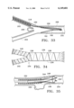
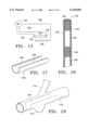
- FIG. 1 is a side elevation, partially sectioned, showing a graft constructed according to the invention and a system for deploying the graft within a blood vessel;
- FIG. 2 is an end view showing the graft constrained within a catheter of the system
- FIG. 3 is an end view showing the graft radially expanded into contact with surrounding tissue of the blood vessel
- FIG. 4 is an end view of the graft in a relaxed state
- FIG. 5 is a plan view of the graft, uncoiled in a planar configuration
- FIG. 6 is a plan view of an alternative embodiment graft, uncoiled to a planar configuration
- FIG. 7 is a plan view of an alternative graft support structure, uncoiled to a planar configuration
- FIG. 8 is a plan view of another alternative graft in a planar configuration
- FIG. 9 is a sectional view taken along the line 9--9 in FIG. 8;
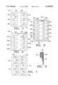
- FIG. 10 is a plan view of another alternative graft, shown uncoiled in a flat configuration to reveal electrical heating elements;
- FIG. 11 is a sectional view taken along the line 11--11 in FIG. 10;
- FIG. 12 is a sectional view similar to that of FIG. 11, showing an alternative construction
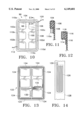
- FIG. 13 is a plan view of another alternative embodiment graft uncoiled in a flat configuration
- FIG. 14 is a more detailed illustration of a portion of FIG. 13;
- FIG. 15 is a schematic illustration of a circuit for providing electrical current to the heating elements
- FIG. 16 is a sectional view showing a portion of a graft with two layers of graft material to provide a pocket
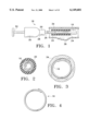
- FIG. 17 is a perspective view of a further alternative graft
- FIG. 18 shows the graft of FIG. 17 deployed in a vessel
- FIG. 19 is a sectional view of the graft and vessel in FIG. 18;
- FIG. 20 is a sectional view of an alternative graft similar to the graft in FIG. 17;
- FIG. 21 is a perspective view of a further alternative graft
- FIG. 22 is an end view of the graft in FIG. 21 illustrating interlocking structural members.
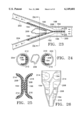
- FIG. 23 is a side elevation of a bifurcated graft, formed according to the present invention, deployed within a vessel;
- FIG. 24 is a sectional view taken along the line 24--24 in FIG. 23;
- FIG. 25 is a sectional view taken along the line 25--25 in FIG. 23;
- FIG. 26 is a plan view of part of the graft
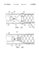
- FIGS. 27 and 28 are side sectional views of an alternative bifurcated graft and system for deploying the graft in a vessel;
- FIG. 29 is a sectional view taken along the line 29--29 in FIG. 27;
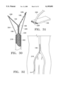
- FIG. 30 is a side sectional view of a further alternative bifurcated graft
- FIG. 31 is a perspective view showing a support member and pull wire of the graft in FIG. 30;
- FIG. 32 illustrates deployment of the graft to FIG. 30 in a branched vessel
- FIG. 33 shows use of an alternative deployment system to position the graft of FIG. 30 in a branched vessel
- FIG. 34 illustrates an alternative embodiment bifurcated graft
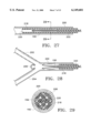
- FIG. 35 illustrates a further alternative graft contained within a catheter distal end and positioned in a vessel
- FIGS. 36-38 illustrate alternative support structures for cylindrical grafts
- FIGS. 39-43 illustrate alternative approaches for securing graft material to a support structure for the graft of FIG. 35;
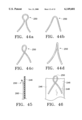
- FIGS. 44a-d illustrate alternative support member end constructions
- FIG. 45 is a sectional view taken along the line 45--45 in FIG. 37;
- FIG. 46 illustrates one of the alternative end constructions and a portion of the graft
- FIGS. 47 and 48 illustrate another embodiment graft and a system for deploying the graft
- FIG. 49 illustrates a further embodiment graft
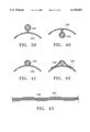
- FIG. 50 is an end view of the graft shown in FIG. 49;
- FIG. 51 illustrates a portion of a system for deploying the graft
- FIGS. 52 and 53 are more detailed views of portions of FIG. 51;
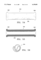
- FIG. 54 illustrates another alternative embodiment graft construction
- FIG. 55 illustrates the graft in section
- FIG. 56 is an end view showing the graft in a collapsed configuration for deployment.
- System 18 includes an elongate flexible catheter 20 with a lumen 22 that runs the length of the catheter.
- Graft 16 is contained within the lumen at a distal end 24 of the catheter.
- a stylet 26 which has bending flexibility but is sufficiently stiff in the axial direction to apply an axial pushing force against the graft.
- catheter 20 is coupled to a housing 30.
- Stylet 26 extends through the housing to a handle 32.
- catheter 20 With the proximal end of the catheter and the housing remaining outside of the body, catheter 20, with graft 16 radially compressed and contained within lumen 22, is guided interlumenally until the catheter distal end and graft are positioned near an intended treatment site, e.g., within a blood vessel 34 where an aneurysm 36 has formed.
- graft 16 When contained in the catheter lumen, graft 16 is coiled or wound in the form of a scroll, in a reduced-radius delivery profile. An elastic restoring force urges the graft to radially expand, but catheter 20 constrains the graft against radial expansion.
- Graft 16 is deployed by moving it axially beyond catheter 20.
- Moving handle 32 moves stylet 26 distally against the graft, moving the graft distally, eventually freeing the graft from catheter 20.
- the graft is substantially uncoiled from its previous scroll-like profile, although a substantial overlap remains.
- FIG. 4 graft 16 is shown in its relaxed state, i.e. with no external radial forces applied to the graft. There is a slight overlapping of the axial end portions, although less than the overlap as shown in FIG. 3. Thus in FIG. 3, there is an equillibrium between an elastic restoring force in the graft (less than when the graft is wound tightly), and a counteracting radial force exerted by the tissue wall of blood vessel 34. These counteracting forces secure graft 16 within vessel 34, so that no hooks or other extraneous securing means are required.
- graft 16 is shown completely unwound to a flat, planar configuration, to more clearly show its two-layered construction.
- the graft includes a structural layer 38, which is the top layer as shown in FIG. 5 and the inside layer when the graft is coiled into its tubular form.
- the other layer is a graft material layer 40.
- the graft material layer is compliant, tending to conform to the shape of structural layer 38.
- the graft layer also is substantially impervious to blood or other body fluids, either being nonporous or of sufficiently low porosity to prevent the passage of blood through it.
- graft 16 shunts blood past the aneurysm, i.e. the graft isolates aneurysm 36 from the blood flow.
- Structural layer 38 is formed as a support frame with a primary section 42 extending longitudinally or axially (vertically as viewed in FIG. 5).
- a plurality of secondary sections 44, 46, 48, 50, 52 and 54 extend transversely from the primary section, arranged in opposed pairs.
- the primary and secondary sections can be likened to a rib cage, with the arcuate secondary "ribs" extending from the primary "backbone.”
- Structural layer 20 may be constructed from memory elastic material (such as nickel titanium), spring stainless steel, thermoset plastic, or other metal or polymeric material.
- the structural layer can be inherently radiopaque as when formed of certain metals, or may be doped with radiopaque materials such as barium or bismuth.
- the primary section and secondary sections can be separate members, bonded together by spot welding or other suitable methods into the desired rib cage configuration. More preferably, the primary and secondary sections are of single-piece construction, stamped from a sheet of the selected structural material. As alternatives, a masking and chemical etching process can be used to form single-piece structural layers; or, a laser or water jet can be employed to mill or cut structural layers from the sheet material, with the water jet being suitable primarily for polymeric sheeting. In any event, multiple structural layers conforming to a predetermined pattern are severed from the sheet of structural material, which can have a thickness of e.g. about 5 miles (0.125 mm).
- the structural layer can be wrapped about a cylindrical mandril having the desired radius, with primary section 42 parallel to the mandril longitudinal axis. Then, with the structural layer wound about the mandril, heat is applied, for example by heating the mandril, in a sufficient amount to thermally set the structural layer. The structural layer, which then tends to assume the relaxed state illustrated in FIG. 4, is allowed to cool, at which point a layer of graft material can be cut to the appropriate size and secured to the structural layer.
- Graft material layer 40 can consist of a woven textile with a porosity (total open area divided by the total surface area) and pore size selected to limit the flow of blood through the graft material. Polyester (DACRON), nylon, and other biocompatible materials whose strands may be woven into a sheet are preferred.
- the graft material layer can be manufactured of extruded, blow molded, or dipped polymers such as PTFE, urethane, polyimide, nylon, silicone, polyethylene, or a combination of these materials.
- the graft material layer is bonded to the structural layer, e.g., using adhesives, thermal bonding, sewing of a folded graft material layer or several layers, or other suitable means. While in some cases the graft material layer can be attached to a flat structural layer before thermal shaping, it frequently is necessary to thermally shape the structural layer before attaching the graft material, due to the high temperatures required for thermal shaping, particularly in the case of metal structural layers.
- Certain vascular treatments do not require a prosthesis impervious to body fluids, although they do require maintaining the patency of a vessel. Stents are frequently suited for such applications.
- the above-described graft fabrication method is suitable for forming prostheses to meet these applications, more particularly by forming structural layers without attaching graft material layers. The result is a rib cage "stent" suitable for and maintaining vessel patency.
- a graft 56 (FIG. 6) is formed with a structural layer 58 with a primary section 60 and transverse secondary sections 62a-62h that are staggered rather than in opposed pairs.
- a graft material layer 64 is secured to the structural layer. Due to the staggering of the secondary sections, there is no overlap of secondary sections, although opposed portions of the graft material do overlap.
- the structural layer can be fabricated in different forms to meet a variety of needs for stents and graphs.
- FIG. 7 shows a structural layer 66 including an axially extending primary section 68, secondary sections 70a-70h extending in opposite directions from the primary section, and opposed axially extending end sections 72 and 74.
- End sections 72 and 74 joined to what in previous embodiments are the free ends of the secondary sections, lends stability and more positively causes the secondary sections to conform to one another in their curvature.
- Structural layer 66 can be thermally shaped to a desired tubular profile as previously described to provide a stent, or shaped and joined with one or more layers of graft material to provide a graft.
- FIG. 8 shows a graft 76 composed of a structural layer 78 and an attached graft material layer 80.
- the structural layer includes an axial primary section 82, and tapered secondary sections or ribs 84a-84j arranged in opposed pairs of ribs. Each rib converges in its width in the transversely outward direction, i.e. in the direction from a base 86 at the primary section to an outward end 88.
- the structural layer further includes a rectangular outer frame 90 including a pair of outward axial sections and an opposed pair of nontapered transverse sections.
- Graft material layer 80 generally behind the structural layer as viewed in FIG. 8, includes a portion 92 that is folded over and covers rectangular frame 90. Portion 92 is secured to the remainder of the graft material layer, to facilitate securing the graft material to the structural layer. As seen in FIG. 9, portion 92 can be bonded with an adhesive as indicated at 94. Thermal bonding and stitching of the graft fabric are suitable alternatives for attaching the graft material.
- secondary sections 84 can be tapered in thickness, in lieu of or in addition to the taper in width. In either event, the result is that the restoring force in the secondary members is not uniform, but rather behaves according to a force gradient determined by the change in the profile of the secondary member. For example, in the graft of FIG. 8, in which the secondary sections converge in the direction away from the primary section, the elastic restoring force is diminished in that direction.
- the secondary sections of the structural layer do not extend linearly in the transverse direction
- the secondary sections or ribs can be parallel to one another, each including a first segment next to the primary section and extended from the primary section at an inclined angle, and a second segment extended from the first segment at an opposite inclined angle, each rib thereby resembling the letter "V.”
- the ribs can have curves or other nonlinear features, so long as there is at least a general transverse extension away from the primary section.
- FIG. 10 illustrates a graft 96 including a structural layer 98 with a longitudinal primary section 100, several untapered secondary sections 102a-102d, and a rectangular frame 104 surrounding the primary and secondary sections.
- An adjacent graft material layer 106 includes a portion 108 folded over and surrounding the rectangular frame and secured to the remaining graft material as previously described.
- Graft 96 also includes a rectangular heating element in the form of a series of elongate electrode strips 110a-110d bonded to the graft material.
- a conductive wire 112 couples the heating element to an RF current source (not shown).
- the current source provides an electrical current to the heating element, which in conjunction with a ground or indifferent electrode (not shown) enables ohmic heating of tissue adjacent the heating element.
- the electrode strips are positioned inside the structural layer, and when the graft is formed into its tubular shape, are flush with the side of the structural layer facing the vessel wall.
- the heating element is positioned to prevent loss of coagulun or thrombi outside the graft into the vessel lumen as the graft is secured. This position also enhances contact between the electrode strips and the vessel wall.
- FIG. 12 An alternative position for the electrode strips is shown in FIG. 12, a sectional view similar to FIG. 11.
- the electrode strips 114 are contained between the graft material 116 and an outer rectangular frame 118 of the structural layer facing the vessel wall.
- This location is preferred when the heating element is a resistive wire, which heats surrounding tissue when current is transmitted through the element. Resistive heating requires an additional signal wire, shown at 120 in FIG. 10.
- Signal wires 112 and 120 may be spot welded or secured with an interference fit to provide an electrical circuit to deliver RF or direct current (DC) energy.
- DC direct current
- the purpose of the heating element is to thermally secure graft 96 to the vessel wall after its deployment.
- the electrode strips may be formed of platinum, platinum-iridium, stainless steel, or gold, and may be threaded through the graft material radially, with a larger surface area exposed to the exterior surface of the graft. Alternatively, the electrode strips are bonded to the graft material on the exterior surface. Regardless of whether RF energy or a direct current is provided, the heating element heats surrounding and adjacent tissue of the blood vessel, thus thermally fusing the graft edges to the vessel walls. As a result, the fixation of the graft is improved, and the graft is better able to withstand pressure fluctuations due to pumping of the heart without becoming dislodged from the implant site.
- Thermal bonding is accompanied by an increase in impedance as a result of the formation of coagulum on the electrode which tends to attach the electrode to the vessel wall.
- the impedance increase can be used to detect such coagulation, and thus to detect thermal bonding of the graft to the vessel wall.
- a threshold amount e.g. 100 ohms above baseline
- temperature sensors can be employed to detect sealing. This is accomplished by forming a thermocouple junction near the signal wire.
- the signal wire can be fabricated of two dissimilar metals to provide a thermocouple junction.
- the RF signal may be pulsed rather than continuous, to provide time for recording thermocouple temperatures.
- a resistive heating element can be caused to produce heat when a direct or RF current is transmitted.
- FIG. 13 shows a split wall graft 122 (planar configuration) with a heating element composed of several thin film resistive heaters 124 in strip form.
- the thin film heaters can be configured by depositing metal conductive lines 126 on a polyimide or another dielectric substrate 128, with signal wires 130 also deposited on the graft and routed to a connector 132 for connection to an energy source. If desired, the thin film resistive strips are segmented to enable selective application of heat to specific regions of the graft.
- the application of heat also increases the kinetics of thrombus formation in the region between the graft and vessel wall. This is thought to promote a more rapid healing of the aneurysm.
- the application of heat also enhances drug delivery or genetic infusion.
- the signal wires are removed from the graft by delivering a direct current through the wires of sufficient amplitude to cause a breakdown of each wire.
- the breakdown location can be selected by producing a weak point of decreased signal wire diameter.
- signal wires may be cleaved by a sharp edge supported by the delivery catheter, near the distal end. After severance, the signal wires are removed from the vasculature.
- a sufficiently thin neck portion can allow a mechanical severance of the signal wire. In any event, since severance exposes the signal wire to the blood stream, the wire must be formed of a biocompatible material.
- FIG. 15 schematically illustrates a circuit for administering RF energy.
- An RF current source 134 located outside the patient, is coupled to a pair of signal wires 136 and 138, each of which is coupled to one of the two heating elements 140 and 142 at opposite ends of a graft 144.
- An indifferent or ground electrode 146 is coupled to the power source through a conductive line 148. The potential difference between the heating elements and the indifferent electrode causes ohmic heating of tissue adjacent to the heating elements.
- FIG. 16 is a sectional view showing a graft 150 in which two graft material layers, indicated at 152 and 154, are provided on opposite sides of a structural layer 156. This construction forms a pocket 158 between spaced apart sections 160 and 162 of the structural layer. The pocket can be loaded with a drug solution, which after implantation is allowed to diffuse into the target vessel over time.
- Suitable drug solutions are fibrinogen adhesives to aid bonding to the vessel wall, heparin to decrease the acute thrombogenisity of the graft material, pharmacological agents (urokinase, TPA, or streptokinase) to lyse thrombi, collagen to promote formation of an endothelial layer, glycerol to increase the radiopacity of the graft material, and tissue plasminogen activators.
- a radiopaque contrast material can be provided for better visualization of the graft.
- outer graft layer 152 can be constructed of a material having a high porosity, while inner graft layer 154 can be fabricated of a relatively nonporous material.
- Different pockets may contain different solutions with different functions.
- a drug solution may be introduced into the graft through piercing with a small gauge needle through the graft material and injecting the drug solution directly into the pockets.
- a homeostatic valve constructed of silicone or other elastomer may be included in the inside graft material layer.
- the graft material also may be impregnated or filled with drug solutions using a vacuum process. While the graft is submerged in a drug solution, a vacuum is applied to draw the drug solution into the graft.
- heating elements to seal the graft also increases diffusion kinetics by causing reversible poration of the cell membranes, to enhance introduction of a drug or genetic solution into the vessel wall or blood stream.
- Relatively large amplitude pulses of d.c. or RF energy can be used to cause electroporation of cell membranes within the vessel wall. Delivery can be highly localized, significantly reducing required amounts as compared to a systemic dosing.
- the pockets facilitate an alternative approach to maintaining an implanted graft in a desired radially-enlarged profile.
- biocompatible foam or adhesives can be provided in the pockets between the graft material layers. These foams or adhesives solidify as they cure, and tend to maintain the graft shape. This facilitates the forming of non-uniform graft shapes as the graft is positioned at the treatment site, and is particularly useful when the graft is positioned in a branching vessel.
- the graft can be heated to reduce curing time.
- ultraviolet light or other light can be used to cure the adhesives.
- FIG. 17 shows an implantable graft 164 formed with a layer and a graft material layer and thermally shaped into a generally tubular shape.
- Graft 164 differs from previously described grafts in that it does not form a complete circumferential closure when in the relaxed state, nor when implanted. Rather, the graft has two axial edges 166 and 168 that remain spaced apart.
- graft 164 is implanted within a vessel 170 having an aneurysm 172 that is localized in the sense that it does not circumferentially surround the vessel.
- a side branch 174 is open to vessel 170, circumferentially spaced apart from the aneurysm.
- the split wall graft is positioned to isolate the aneurysm from the blood flow, while at the same time the gap between axial edges 166 and 168 is aligned with side branch 174, to maintain its patency.
- This graft is suitable for treating dissecting aneurysms where a target fissure may be located.
- the graft when expanded radially to the relaxed state, should have a circumferential extent greater than 180 degrees to insure intimate contact with the vessel wall.
- the ends of this type of graft can be provided with hooks 176 to enhance graft fixation, and particular to prevent circumferential shifting. Further, heating elements can be provided for thermal bonding.
- FIGS. 21 and 22 Another alternative embodiment graft 178, shown in FIGS. 21 and 22, includes a graft material layer 180 secured to a support structure that includes axial members 182 along the axial edges and at intermediate locations, and circumferential members 184. Graft 178, like the previously discussed grafts, is radially collapsed by winding it into a tighter coil or scroll. The opposed axial ends can overlap one another as previously described. Alternatively, as seen in FIG. 22, circumferential support members 186 near the axial ends can be shaped to provide an interlocking of the graft in a selected profile, to augment the elastic restoring force.
- FIG. 23 shows a further embodiment, namely a bifurcated graft 190 implanted in a branched vessel 192, e.g., where the abdominal aorta branches into the iliac arteries.
- Graft 190 includes two structural layers with respective primary sections 194 and 196. Over a portion of their lengths, the primary sections are joined together to provide a main stem 198 of the support structure implanted in a main vessel 200. Over the rest of their lengths, the primary sections are separated from one another at an angle, so that the structural layers in section resemble the letter "Y.” Each primary section extends into a different one of branching vessels 202 and 204.
- FIGS. 24 and 25 are sectional views, taken along the graft stem portion and branching portions, respectively, illustrating the extension of secondary sections 210-216 from their respective primary sections.
- the angle between primary sections 194 and 196 when graft 190 is in the relaxed state can be configured to provide an elastic restoring force against branching vessels 202 and 204, to help maintain the graft in place.
- Each of the structural layers can be fabricated initially by stamping them from a flat sheet for a planar configuration as seen in FIG. 26, then later thermally shaping them to the desired radius.
- graft material layer 208 is secured to the free ends of the secondary sections and can be bonded to the support structure at other locations if desired. Suitable modifications include providing branching portions of the graft with unequal lengths to account for non-uniform branching vessels or to limit advancement of one of the branching legs. The angle between branching legs in the relaxed state also can be selected to fit different vessels.
- the ribs or secondary sections can be tapered as shown to vary the restoring force against the vessel wall, and rib thickness likewise can be varied.
- FIGS. 27 through 29 show a system for deploying graft 190, including a catheter 218 with a lumen 220 for containing the graft and a stylet 222 axially movable within the lumen, to abut a proximal end of the graft and advance the graft distally beyond the catheter, allowing the branching legs to separate from one another and also allowing radial expansion along the branches and the proximal stem where the primary sections are connected.
- FIGS. 30 and 31 show an alternative deployment system in which catheter lumen 220 also contains a pair of wires 224 and 226 coupled to the distal ends of primary sections 194 and 196, respectively.
- the wires are anchored by hooks or rivets 228 inserted through the graft material layer.
- FIGS. 32 and 33 illustrate another alternative deployment approach in which the catheter is advanced through one of the branching vessels toward the main vessel.
- a stylet 230 includes a hooked end 232 for moving the graft proximally, i.e., toward the branching vessels as viewed in FIG. 33, as the stylet is moved proximally.
- FIG. 34 illustrates an alternative bifurcated graft 234 in which a graft material layer 236 is supported by coiled support members 238, 240 and 242.
- FIG. 35 shows an implantable graft 244 of continuous rather than split end form, including a graft material layer 246 and a support structure 248 with looped terminal ends 250 that extend beyond the graft material.
- the graft is shown partially deployed from a catheter 252 within a vessel 254 having an aneurysm 256.
- FIGS. 36-38 show alternative support structure arrangements, including a series of elliptical loops 258 in FIG. 36, a continuous strand forming longitudinal extensions 260 and loops 262 joining adjacent longitudinal members in FIG. 37, and a helical or coiled arrangement of a single strand 264 in FIG. 38.
- the pitch between adjacent helical windings varies, with substantially closer spacing between adjacent turns of the coil near the graft ends, to provide more positive support (elastic radial expansion) against the vessel wall.
- FIGS. 39-43 illustrate a variety of approaches to joining the support structure and graft material, including bonding the graft material 246 to itself when it surrounds the supporting strand 258 as in FIGS. 39 and 40.
- the support members 262 can be laminated in the graft material, as shown in FIG. 41.
- Support strands wound about in initial graft layer can be dipped in future graft material to achieve this result.
- Separate layers of graft material can be bonded together about a support strand, as shown in FIG. 42.
- the graft material 246 and strands 262 can be interwoven, as shown in FIG. 43.
- the terminal ends 250 of the support strands can be shaped in a variety of ways, as seen in FIGS. 44a-d.
- the longitudinal strand arrangement of FIG. 37 can have outwardly flared end loops, as indicated in FIG. 45.
- FIG. 46 shows the loop of FIG. 44c partially extended beyond the graft material.
- FIGS. 47 and 48 show a system for deploying graft 244, including a catheter 266 having a lumen 268, a stylet 270 contained within the lumen and moveable axially relative to the catheter, and a suture 272, contained within the stylet and further threaded through the terminal ends 250 of the graft. As indicated, pulling the suture proximally brings the terminal ends together, thus radially reducing graft 244 at least near its proximal end. This feature enables a radial reduction and repositioning of a partially deployed graft.
- FIGS. 49-51 show a further alternative embodiment graft 274 and a mechanism for deploying the graft.
- Graft 274 includes a cylindrical graft material layer 276, and four generally axial and circumferentially spaced apart elongate support members 278-284.
- the support members are flat and have a sinusoidal curvature as seen in connection with members 278 and 282 in FIG. 49. As best seen in FIG. 50, the curvature is reduced when opposite ends of the graft are pulled further axially apart from one another.
- stylets 286 and 288 The axial distance between the opposite graft ends is controlled by a pair of stylets 286 and 288. As seen in FIGS. 52 and 53, interior stylet 286 is coupled to the distal end of the graft through hooks 290, and outer stylet 288 is coupled to the proximal graft end through hooks 292. Stylet 286 is moveable axially relative to stylet 288, to adjust the distance between the opposite graft ends, and thus also adjust the graft radius.
- FIGS. 54-56 show a graft 294 consisting of a graft material layer 296, i.e., having no rib cage or other support structure.
- Graft 294 is formed of a resilient elastomer, woven or otherwise formed into walls sufficiently thick to provide a residual force that radially expands the graft into intimate contact with surrounding blood vessel tissue. At the same time, porosily is sufficiently low to isolate an aneurysm or other vessel abnormality.
- the opposite ends of the graft can be flared radially outward as indicated at 298, to more positively prevent leakage between the graft and vessel wall, and to prevent axial motion of the implanted graft.
- the elastic graft is readily collapsed by folding and stretching, into the reduced profile shown in FIG. 56.
- the graft can be deployed by one of the previously described systems.
- a prosthesis is formable elastically into a reduced-radius profile, and expands radially at the implant site to establish firm contact against tissue.
- the grafts have support structures of primary and secondary sections that can be shaped to accommodate irregular vessels or to provide residual force gradients. Grafts constructed of resilient material, and not requiring separate support structures, can accommodate narrower vessels.
Abstract
Description
Claims (42)
Priority Applications (2)
| Application Number | Priority Date | Filing Date | Title |
|---|---|---|---|
| US08/932,566 US6149681A (en) | 1996-09-20 | 1997-09-19 | Radially expanding prostheses and systems for their deployment |
| US09/415,776 US6293955B1 (en) | 1996-09-20 | 1999-10-08 | Percutaneous bypass graft and securing system |
Applications Claiming Priority (3)
| Application Number | Priority Date | Filing Date | Title |
|---|---|---|---|
| US2659296P | 1996-09-20 | 1996-09-20 | |
| US4462597P | 1997-04-18 | 1997-04-18 | |
| US08/932,566 US6149681A (en) | 1996-09-20 | 1997-09-19 | Radially expanding prostheses and systems for their deployment |
Related Parent Applications (1)
| Application Number | Title | Priority Date | Filing Date |
|---|---|---|---|
| US08/966,003 Continuation US5989276A (en) | 1996-09-20 | 1997-11-07 | Percutaneous bypass graft and securing system |
Related Child Applications (1)
| Application Number | Title | Priority Date | Filing Date |
|---|---|---|---|
| US64408400A Continuation | 1996-09-20 | 2000-08-22 |
Publications (1)
| Publication Number | Publication Date |
|---|---|
| US6149681A true US6149681A (en) | 2000-11-21 |
Family
ID=26701427
Family Applications (1)
| Application Number | Title | Priority Date | Filing Date |
|---|---|---|---|
| US08/932,566 Expired - Fee Related US6149681A (en) | 1996-09-20 | 1997-09-19 | Radially expanding prostheses and systems for their deployment |
Country Status (4)
| Country | Link |
|---|---|
| US (1) | US6149681A (en) |
| EP (1) | EP1011524A4 (en) |
| AU (1) | AU4489197A (en) |
| WO (1) | WO1998011847A1 (en) |
Cited By (123)
| Publication number | Priority date | Publication date | Assignee | Title |
|---|---|---|---|---|
| US6347247B1 (en) | 1998-05-08 | 2002-02-12 | Genetronics Inc. | Electrically induced vessel vasodilation |
| US6371964B1 (en) | 1999-05-18 | 2002-04-16 | Vascular Innovations, Inc. | Trocar for use in deploying an anastomosis device and method of performing anastomosis |
| US20020077693A1 (en) * | 2000-12-19 | 2002-06-20 | Barclay Bruce J. | Covered, coiled drug delivery stent and method |
| US20020099394A1 (en) * | 1998-06-10 | 2002-07-25 | Houser Russell A. | Sutureless anastomosis systems |
| US6461320B1 (en) | 1998-08-12 | 2002-10-08 | Cardica, Inc. | Method and system for attaching a graft to a blood vessel |
| US6471713B1 (en) | 2000-11-13 | 2002-10-29 | Cardica, Inc. | System for deploying an anastomosis device and method of performing anastomosis |
| WO2002094081A2 (en) * | 2001-05-18 | 2002-11-28 | Frazier Howard O M D | Method and apparatus for surgically restoring coronary blood vessels |
| US6494889B1 (en) | 1999-09-01 | 2002-12-17 | Converge Medical, Inc. | Additional sutureless anastomosis embodiments |
| US20020193785A1 (en) * | 1998-12-31 | 2002-12-19 | Morteza Naghavi | Method and apparatus for heating inflammed tissue |
| US6497710B2 (en) | 1998-08-12 | 2002-12-24 | Cardica, Inc. | Method and system for attaching a graft to a blood vessel |
| US6506437B1 (en) | 2000-10-17 | 2003-01-14 | Advanced Cardiovascular Systems, Inc. | Methods of coating an implantable device having depots formed in a surface thereof |
| US20030014063A1 (en) * | 1996-11-08 | 2003-01-16 | Houser Russell A. | Percutaneous bypass graft and securing system |
| US6537288B2 (en) | 1999-05-18 | 2003-03-25 | Cardica, Inc. | Implantable medical device such as an anastomosis device |
| US6544582B1 (en) * | 2001-01-05 | 2003-04-08 | Advanced Cardiovascular Systems, Inc. | Method and apparatus for coating an implantable device |
| US20030093095A1 (en) * | 2001-07-05 | 2003-05-15 | Whayne James G. | Distal anastomosis system |
| US20030167064A1 (en) * | 1999-09-01 | 2003-09-04 | Whayne James G. | Advanced anastomosis systems (II) |
| US6626920B2 (en) | 2001-07-05 | 2003-09-30 | Converge Medical, Inc. | Distal anastomosis system |
| US6641607B1 (en) | 2000-12-29 | 2003-11-04 | Advanced Cardiovascular Systems, Inc. | Double tube stent |
| US20030229365A1 (en) * | 2002-06-10 | 2003-12-11 | Whayne James G. | Angled vascular anastomosis system |
| US6669624B2 (en) | 2002-03-26 | 2003-12-30 | O. Howard Frazier | Temporary heart-assist system |
| US6673088B1 (en) | 1999-05-18 | 2004-01-06 | Cardica, Inc. | Tissue punch |
| US20040068278A1 (en) * | 1999-12-06 | 2004-04-08 | Converge Medical Inc. | Anastomosis systems |
| US6719769B2 (en) | 1999-11-15 | 2004-04-13 | Cardica, Inc. | Integrated anastomosis tool with graft vessel attachment device and cutting device |
| US20040092989A1 (en) * | 2002-08-28 | 2004-05-13 | Heart Leaflet Technologies, Inc | Delivery device for leaflet valve |
| US20040106989A1 (en) * | 2002-07-03 | 2004-06-03 | Wilson Robert F. | Leaflet reinforcement for regurgitant valves |
| US6764512B2 (en) * | 2000-04-04 | 2004-07-20 | Link Spine Group, Inc. | Plastic implant with channel for radiographic contrast wire |
| US6776785B1 (en) | 2000-10-12 | 2004-08-17 | Cardica, Inc. | Implantable superelastic anastomosis device |
| US6776604B1 (en) | 2001-12-20 | 2004-08-17 | Trivascular, Inc. | Method and apparatus for shape forming endovascular graft material |
| US20040225373A1 (en) * | 2003-05-05 | 2004-11-11 | Scimed Life Systems, Inc. | Tissue patches and related delivery systems and methods |
| US20040225247A1 (en) * | 2003-05-05 | 2004-11-11 | Scimed Life Systems, Inc. | Tissue patches and related delivery systems and methods |
| US6858035B2 (en) | 2001-07-05 | 2005-02-22 | Converge Medical, Inc. | Distal anastomosis system |
| US20050060020A1 (en) * | 2003-09-17 | 2005-03-17 | Scimed Life Systems, Inc. | Covered stent with biologically active material |
| US20050090888A1 (en) * | 2003-10-28 | 2005-04-28 | Hines Richard A. | Pleated stent assembly |
| US20050251163A1 (en) * | 2001-07-05 | 2005-11-10 | Converge Medical, Inc. | Vascular anastomosis systems |
| US6974473B2 (en) | 2000-06-30 | 2005-12-13 | Vascular Architects, Inc. | Function-enhanced thrombolytic AV fistula and method |
| US20060047218A1 (en) * | 2002-04-17 | 2006-03-02 | Matthew Bloom | User-retainable temperature and impedance monitoring methods and devices |
| US20060058870A1 (en) * | 2004-09-14 | 2006-03-16 | Vascular Architects, Inc., A Delaware Corporation | Covered stent with controlled therapeutic agent diffusion |
| US20060095124A1 (en) * | 2003-06-13 | 2006-05-04 | Stefan Benz | Suction stent |
| US7074235B1 (en) * | 1999-10-16 | 2006-07-11 | Sumit Roy | Low-profile, non-stented prosthesis for transluminal implantation |
| US7090693B1 (en) * | 2001-12-20 | 2006-08-15 | Boston Scientific Santa Rosa Corp. | Endovascular graft joint and method for manufacture |
| US20060246210A1 (en) * | 2005-04-29 | 2006-11-02 | Vascular Architects Inc., A Delaware Corporation | Method for making a covered drug-eluting stent |
| US20080027531A1 (en) * | 2004-02-12 | 2008-01-31 | Reneker Darrell H | Stent for Use in Cardiac, Cranial, and Other Arteries |
| EP1920724A1 (en) * | 2006-11-07 | 2008-05-14 | Medtronic Vascular, Inc. | Cutting radio frequency catheter for creating fenestrations in graft cloth |
| US20080140181A1 (en) * | 2004-10-25 | 2008-06-12 | Reynolds Jason M | Stent Removal and Repositioning Aid and Associated Method |
| WO2009055615A1 (en) * | 2007-10-23 | 2009-04-30 | Endologix, Inc. | Stent |
| US20090299443A1 (en) * | 2008-05-30 | 2009-12-03 | Boston Scientific Scimed, Inc. | Guide catheter having vasomodulating electrodes |
| JP2009291626A (en) * | 2001-12-20 | 2009-12-17 | Trivascular2 Inc | Method and apparatus for manufacturing endovascular graft section |
| US20100049297A1 (en) * | 2008-08-21 | 2010-02-25 | C.R. Bard, Inc. | Method of loading a stent into a sheath |
| US7678217B2 (en) | 2001-12-20 | 2010-03-16 | Trivascular2, Inc. | Method for manufacturing an endovascular graft section |
| US20100106255A1 (en) * | 2008-10-24 | 2010-04-29 | Dubin Marc G | Self-expanding frontal sinus stent and insertion tool |
| US20100191317A1 (en) * | 1999-11-19 | 2010-07-29 | Advanced Bio Prosthetic Surfaces, Ltd., A Wholly Owned Subsidiary Of Palmaz Scientific, Inc. | Endoluminal implantable stent-grafts |
| US20100249907A1 (en) * | 2007-10-17 | 2010-09-30 | C.R. Band Inc | Delivery system for a self-expanding device for placement in a bodily lumen |
| US20110060397A1 (en) * | 2008-05-09 | 2011-03-10 | C.R. Bard, Inc. | Method of loading a stent into a sheath |
| US20110137396A1 (en) * | 2009-12-03 | 2011-06-09 | C. R. Bard, Inc. | Stent device delivery system with inwardly tapering stent bed |
| US20110137400A1 (en) * | 2009-12-03 | 2011-06-09 | C. R. Bard, Inc. | Stent device delivery system with a varying radial profile pull member |
| US20110137402A1 (en) * | 2009-12-03 | 2011-06-09 | C. R. Bard, Inc. | Stent device delivery system with a heat shrink resistant support member |
| US20110137401A1 (en) * | 2009-12-03 | 2011-06-09 | C. R. Bard, Inc. | Stent device delivery system with an outer sheath polymeric reinforcement layer |
| US8012164B1 (en) | 2002-01-22 | 2011-09-06 | Cardica, Inc. | Method and apparatus for creating an opening in the wall of a tubular vessel |
| US8066755B2 (en) | 2007-09-26 | 2011-11-29 | Trivascular, Inc. | System and method of pivoted stent deployment |
| US8083789B2 (en) | 2007-11-16 | 2011-12-27 | Trivascular, Inc. | Securement assembly and method for expandable endovascular device |
| US8162963B2 (en) | 2004-06-17 | 2012-04-24 | Maquet Cardiovascular Llc | Angled anastomosis device, tools and method of using |
| US8187315B1 (en) * | 2006-12-08 | 2012-05-29 | Cardica, Inc. | Partial stent for treatment of a vascular aneurysm |
| US8196279B2 (en) | 2008-02-27 | 2012-06-12 | C. R. Bard, Inc. | Stent-graft covering process |
| US8221494B2 (en) | 2008-02-22 | 2012-07-17 | Endologix, Inc. | Apparatus and method of placement of a graft or graft system |
| US8226701B2 (en) | 2007-09-26 | 2012-07-24 | Trivascular, Inc. | Stent and delivery system for deployment thereof |
| US8328861B2 (en) | 2007-11-16 | 2012-12-11 | Trivascular, Inc. | Delivery system and method for bifurcated graft |
| US8328860B2 (en) | 2007-03-13 | 2012-12-11 | Covidien Lp | Implant including a coil and a stretch-resistant member |
| US8337650B2 (en) | 1995-03-10 | 2012-12-25 | Bard Peripheral Vascular, Inc. | Methods for making a supported graft |
| US20130006135A1 (en) * | 2010-03-18 | 2013-01-03 | Dixi Microtechniques | Process for manufacturing an electrode for medical use and electrode obtained by the implementation of this process |
| US8361136B2 (en) | 1998-02-09 | 2013-01-29 | Trivascular, Inc. | Endovascular graft |
| US8361092B1 (en) | 2007-06-18 | 2013-01-29 | Wilson T. Asfora | Vascular anastomosis device and method |
| US20130053872A1 (en) * | 2011-08-23 | 2013-02-28 | Cook Medical Technologies Llc | Device and method for preventing blood flow into an aneurysm |
| US8414635B2 (en) | 1999-02-01 | 2013-04-09 | Idev Technologies, Inc. | Plain woven stents |
| US8419788B2 (en) | 2006-10-22 | 2013-04-16 | Idev Technologies, Inc. | Secured strand end devices |
| US8449905B2 (en) | 2001-10-22 | 2013-05-28 | Covidien Lp | Liquid and low melting coatings for stents |
| US20130237929A1 (en) * | 2010-03-09 | 2013-09-12 | Solinas Medical Inc. | Self-closing devices and methods for making and using them |
| US8617441B2 (en) | 1995-03-10 | 2013-12-31 | Bard Peripheral Vascular, Inc. | Methods for making an encapsulated stent |
| US8617337B2 (en) | 1999-02-02 | 2013-12-31 | Bard Peripheral Vascular, Inc. | Partial encapsulation of stents |
| US8663309B2 (en) | 2007-09-26 | 2014-03-04 | Trivascular, Inc. | Asymmetric stent apparatus and method |
| US8690816B2 (en) | 2007-08-02 | 2014-04-08 | Bioconnect Systems, Inc. | Implantable flow connector |
| US8777978B2 (en) | 2006-04-17 | 2014-07-15 | Covidien Lp | System and method for mechanically positioning intravascular implants |
| US8777979B2 (en) | 2006-04-17 | 2014-07-15 | Covidien Lp | System and method for mechanically positioning intravascular implants |
| US8801747B2 (en) | 2007-03-13 | 2014-08-12 | Covidien Lp | Implant, a mandrel, and a method of forming an implant |
| US20140257320A1 (en) * | 2013-03-11 | 2014-09-11 | Microvention, Inc. | Implantable Device With Adhesive Properties |
| US8876881B2 (en) | 2006-10-22 | 2014-11-04 | Idev Technologies, Inc. | Devices for stent advancement |
| US8945202B2 (en) | 2009-04-28 | 2015-02-03 | Endologix, Inc. | Fenestrated prosthesis |
| US8992595B2 (en) | 2012-04-04 | 2015-03-31 | Trivascular, Inc. | Durable stent graft with tapered struts and stable delivery methods and devices |
| US9011480B2 (en) | 2012-01-20 | 2015-04-21 | Covidien Lp | Aneurysm treatment coils |
| US9023095B2 (en) | 2010-05-27 | 2015-05-05 | Idev Technologies, Inc. | Stent delivery system with pusher assembly |
| US9050095B2 (en) | 2004-09-22 | 2015-06-09 | Covidien Lp | Medical implant |
| US9168164B2 (en) | 2010-12-01 | 2015-10-27 | C. R. Bard, Inc. | Device to release a self-expanding implant |
| US9282967B2 (en) | 2007-08-02 | 2016-03-15 | Bioconnect Systems, Inc. | Implantable flow connector |
| US9358140B1 (en) | 2009-11-18 | 2016-06-07 | Aneuclose Llc | Stent with outer member to embolize an aneurysm |
| US20160302909A1 (en) * | 2015-04-16 | 2016-10-20 | Sanford Health | Vessel Filter and Methods for Use |
| US9498363B2 (en) | 2012-04-06 | 2016-11-22 | Trivascular, Inc. | Delivery catheter for endovascular device |
| US9579104B2 (en) | 2011-11-30 | 2017-02-28 | Covidien Lp | Positioning and detaching implants |
| US9585681B2 (en) | 2005-04-04 | 2017-03-07 | Intersect Ent, Inc. | Device and methods for treating paranasal sinus conditions |
| US9687245B2 (en) | 2012-03-23 | 2017-06-27 | Covidien Lp | Occlusive devices and methods of use |
| EP3192466A1 (en) * | 2016-01-15 | 2017-07-19 | Cook Medical Technologies LLC | Medical device |
| US9713475B2 (en) | 2014-04-18 | 2017-07-25 | Covidien Lp | Embolic medical devices |
| EP3210558A1 (en) * | 2016-01-15 | 2017-08-30 | Cook Medical Technologies LLC | Medical device |
| US20170258611A1 (en) * | 2014-05-09 | 2017-09-14 | Mayo Foundation For Medical Education And Research | Devices and methods for forming stents in vivo |
| US9782283B2 (en) | 2008-08-01 | 2017-10-10 | Intersect Ent, Inc. | Methods and devices for crimping self-expanding devices |
| US9907684B2 (en) | 2013-05-08 | 2018-03-06 | Aneuclose Llc | Method of radially-asymmetric stent expansion |
| WO2018089419A1 (en) * | 2016-11-09 | 2018-05-17 | Boston Scientific Scimed, Inc. | Deployable sleeves and related methods |
| US10004507B2 (en) | 2007-06-18 | 2018-06-26 | Asfora Ip, Llc | Vascular anastomosis device and method |
| US10010651B2 (en) | 2007-12-18 | 2018-07-03 | Intersect Ent, Inc. | Self-expanding devices and methods therefor |
| US10028747B2 (en) | 2008-05-01 | 2018-07-24 | Aneuclose Llc | Coils with a series of proximally-and-distally-connected loops for occluding a cerebral aneurysm |
| US10159557B2 (en) | 2007-10-04 | 2018-12-25 | Trivascular, Inc. | Modular vascular graft for low profile percutaneous delivery |
| US10206681B2 (en) | 2007-06-18 | 2019-02-19 | Asfora Ip, Llc | Vascular anastomosis device and method |
| US10232152B2 (en) | 2013-03-14 | 2019-03-19 | Intersect Ent, Inc. | Systems, devices, and method for treating a sinus condition |
| US10271979B2 (en) | 2008-12-31 | 2019-04-30 | C. R . Bard, Inc. | Stent delivery device with rolling stent retaining sheath |
| US10357640B2 (en) | 2009-05-15 | 2019-07-23 | Intersect Ent, Inc. | Expandable devices and methods for treating a nasal or sinus condition |
| US10434293B2 (en) | 2012-04-15 | 2019-10-08 | Tva Medical, Inc. | Implantable flow connector |
| US10596017B2 (en) | 2016-04-25 | 2020-03-24 | Solinas Medical Inc. | Self-sealing tubular grafts, patches, and methods for making and using them |
| US10595888B2 (en) | 2013-04-13 | 2020-03-24 | Solinas Medical Inc. | Self-closing devices and apparatus and methods for making and delivering them |
| US10632293B2 (en) | 2012-04-15 | 2020-04-28 | Tva Medical, Inc. | Delivery system for implantable flow connector |
| US10716573B2 (en) | 2008-05-01 | 2020-07-21 | Aneuclose | Janjua aneurysm net with a resilient neck-bridging portion for occluding a cerebral aneurysm |
| US11129737B2 (en) | 2015-06-30 | 2021-09-28 | Endologix Llc | Locking assembly for coupling guidewire to delivery system |
| US11291812B2 (en) | 2003-03-14 | 2022-04-05 | Intersect Ent, Inc. | Sinus delivery of sustained release therapeutics |
| US11406518B2 (en) | 2010-11-02 | 2022-08-09 | Endologix Llc | Apparatus and method of placement of a graft or graft system |
| US11590008B2 (en) * | 2014-10-02 | 2023-02-28 | Boston Scientific Scimed, Inc. | Controlled ingrowth feature for antimigration |
| WO2023167762A1 (en) * | 2022-03-02 | 2023-09-07 | Covidien Lp | Expandable devices and associated systems and methods |
Families Citing this family (13)
| Publication number | Priority date | Publication date | Assignee | Title |
|---|---|---|---|---|
| US6156064A (en) * | 1998-08-14 | 2000-12-05 | Schneider (Usa) Inc | Stent-graft-membrane and method of making the same |
| US6322585B1 (en) | 1998-11-16 | 2001-11-27 | Endotex Interventional Systems, Inc. | Coiled-sheet stent-graft with slidable exo-skeleton |
| US6325820B1 (en) | 1998-11-16 | 2001-12-04 | Endotex Interventional Systems, Inc. | Coiled-sheet stent-graft with exo-skeleton |
| AU772868C (en) * | 1999-02-01 | 2005-08-11 | Board Of Regents, The University Of Texas System | Woven bifurcated and trifurcated stents and methods for making the same |
| US6312463B1 (en) * | 2000-02-01 | 2001-11-06 | Endotex Interventional Systems, Inc. | Micro-porous mesh stent with hybrid structure |
| EP1326672A4 (en) * | 2000-10-18 | 2007-03-07 | Nmt Medical Inc | Over-the-wire interlock attachment/detachment mechanism |
| NL1017672C2 (en) * | 2001-03-22 | 2002-09-24 | Hendrik Glastra | Implantable assembly with therapeutic effect. |
| US7033389B2 (en) | 2001-10-16 | 2006-04-25 | Scimed Life Systems, Inc. | Tubular prosthesis for external agent delivery |
| US20040034405A1 (en) * | 2002-07-26 | 2004-02-19 | Dickson Andrew M. | Axially expanding polymer stent |
| FR2874812B1 (en) * | 2004-09-07 | 2007-06-15 | Perouse Soc Par Actions Simpli | INTERCHANGEABLE PROTHETIC VALVE |
| US20100131043A1 (en) * | 2008-11-26 | 2010-05-27 | Casas Jesus W | Endoluminal Implants For Bioactive Material Delivery |
| CN109561957B (en) * | 2016-08-05 | 2021-06-15 | W.L.戈尔及同仁股份有限公司 | Integrated medical device of constrained lumen |
| WO2023154563A1 (en) * | 2022-02-14 | 2023-08-17 | Boston Scientific Scimed, Inc. | Sealing device for closing a large bore access opening |
Citations (43)
| Publication number | Priority date | Publication date | Assignee | Title |
|---|---|---|---|---|
| US4877030A (en) * | 1988-02-02 | 1989-10-31 | Andreas Beck | Device for the widening of blood vessels |
| US5078736A (en) * | 1990-05-04 | 1992-01-07 | Interventional Thermodynamics, Inc. | Method and apparatus for maintaining patency in the body passages |
| US5100429A (en) * | 1989-04-28 | 1992-03-31 | C. R. Bard, Inc. | Endovascular stent and delivery system |
| US5123917A (en) * | 1990-04-27 | 1992-06-23 | Lee Peter Y | Expandable intraluminal vascular graft |
| US5306294A (en) * | 1992-08-05 | 1994-04-26 | Ultrasonic Sensing And Monitoring Systems, Inc. | Stent construction of rolled configuration |
| US5354309A (en) * | 1991-10-11 | 1994-10-11 | Angiomed Ag | Apparatus for widening a stenosis in a body cavity |
| US5383926A (en) * | 1992-11-23 | 1995-01-24 | Children's Medical Center Corporation | Re-expandable endoprosthesis |
| US5405322A (en) * | 1993-08-12 | 1995-04-11 | Boston Scientific Corporation | Method for treating aneurysms with a thermal source |
| US5411550A (en) * | 1991-09-16 | 1995-05-02 | Atrium Medical Corporation | Implantable prosthetic device for the delivery of a bioactive material |
| US5433723A (en) * | 1991-10-11 | 1995-07-18 | Angiomed Ag | Apparatus for widening a stenosis |
| US5441515A (en) * | 1993-04-23 | 1995-08-15 | Advanced Cardiovascular Systems, Inc. | Ratcheting stent |
| US5443497A (en) * | 1993-11-22 | 1995-08-22 | The Johns Hopkins University | Percutaneous prosthetic by-pass graft and method of use |
| WO1996022745A1 (en) * | 1995-01-23 | 1996-08-01 | Schneider (Usa) Inc. | Percutaneous stent-graft and method for delivery thereof |
| US5549662A (en) * | 1994-11-07 | 1996-08-27 | Scimed Life Systems, Inc. | Expandable stent using sliding members |
| US5618301A (en) * | 1993-10-07 | 1997-04-08 | Angiomed Ag | Reducing stent, device with reducing stent and use of a reducing stent |
| US5665117A (en) * | 1995-11-27 | 1997-09-09 | Rhodes; Valentine J. | Endovascular prosthesis with improved sealing means for aneurysmal arterial disease and method of use |
| WO1997043961A1 (en) * | 1996-05-17 | 1997-11-27 | Jan Otto Solem | A by-pass graft |
| US5707386A (en) * | 1993-02-04 | 1998-01-13 | Angiomed Gmbh & Company Medizintechnik Kg | Stent and method of making a stent |
| WO1998003118A1 (en) * | 1996-07-24 | 1998-01-29 | Jan Otto Solem | Anastomotic fitting |
| US5716393A (en) * | 1994-05-26 | 1998-02-10 | Angiomed Gmbh & Co. Medizintechnik Kg | Stent with an end of greater diameter than its main body |
| WO1998007399A1 (en) * | 1996-08-23 | 1998-02-26 | Beth Israel Deaconess Medical Center | CATHETER APPARATUS AND METHOD USING A SHAPE-MEMORY ALLOY CUFF FOR CREATING A BYPASS GRAFT $i(IN VIVO) |
| US5733327A (en) * | 1994-10-17 | 1998-03-31 | Igaki; Keiji | Stent for liberating drug |
| WO1998019632A1 (en) * | 1996-11-07 | 1998-05-14 | Vascular Science Inc. | Artificial tubular body organ grafts |
| WO1998019732A1 (en) * | 1996-11-07 | 1998-05-14 | Vascular Science Inc. | Steerable instrument for use in medical procedures |
| WO1998019634A2 (en) * | 1996-11-07 | 1998-05-14 | Vascular Science Inc. | Medical grafting methods and apparatus |
| WO1998019608A1 (en) * | 1996-11-07 | 1998-05-14 | Vascular Science Inc. | Medical instrument with extendable snare |
| WO1998019631A1 (en) * | 1996-11-07 | 1998-05-14 | Vascular Science Inc. | Artificial medical graft methods and apparatus |
| WO1998019635A1 (en) * | 1996-11-07 | 1998-05-14 | Vascular Science Inc. | Methods and apparatus for handling tubing used in medical procedures |
| WO1998019618A1 (en) * | 1996-11-07 | 1998-05-14 | Vascular Science Inc. | Tubular body structure marking methods and apparatus |
| WO1998019629A2 (en) * | 1996-11-07 | 1998-05-14 | Vascular Science Inc. | Medical grafting connectors and fasteners |
| WO1998019636A2 (en) * | 1996-11-07 | 1998-05-14 | Vascular Science Inc. | Medical grafting methods and apparatus |
| WO1998019630A2 (en) * | 1996-11-07 | 1998-05-14 | Vascular Science Inc. | Tubular medical graft connectors |
| US5934286A (en) * | 1991-07-03 | 1999-08-10 | Maginot Vascular Systems | Bypass grafting method which uses a number of balloon catheters to inhibit blood flow to an anastomosis site |
| US5938696A (en) * | 1994-02-09 | 1999-08-17 | Boston Scientific Technology, Inc. | Bifurcated endoluminal prosthesis |
| US5938672A (en) * | 1996-07-26 | 1999-08-17 | Kensey Nash Corporation | System and method of use for revascularizing stenotic bypass grafts and other blood vessels |
| US5944730A (en) * | 1997-05-19 | 1999-08-31 | Cardio Medical Solutions, Inc. | Device and method for assisting end-to-side anastomosis |
| US5944738A (en) * | 1998-02-06 | 1999-08-31 | Aga Medical Corporation | Percutaneous catheter directed constricting occlusion device |
| US5944019A (en) * | 1996-08-13 | 1999-08-31 | Heartstent Corporation | Closed chest coronary bypass |
| US5944750A (en) * | 1997-06-30 | 1999-08-31 | Eva Corporation | Method and apparatus for the surgical repair of aneurysms |
| US5957940A (en) * | 1997-06-30 | 1999-09-28 | Eva Corporation | Fasteners for use in the surgical repair of aneurysms |
| US5968089A (en) * | 1996-08-21 | 1999-10-19 | Krajicek; Milan | Internal shield of an anastomosis in a vascular system |
| US5972017A (en) * | 1997-04-23 | 1999-10-26 | Vascular Science Inc. | Method of installing tubular medical graft connectors |
| US6010529A (en) * | 1996-12-03 | 2000-01-04 | Atrium Medical Corporation | Expandable shielded vessel support |
Family Cites Families (6)
| Publication number | Priority date | Publication date | Assignee | Title |
|---|---|---|---|---|
| US5360443A (en) * | 1990-06-11 | 1994-11-01 | Barone Hector D | Aortic graft for repairing an abdominal aortic aneurysm |
| US5720776A (en) * | 1991-10-25 | 1998-02-24 | Cook Incorporated | Barb and expandable transluminal graft prosthesis for repair of aneurysm |
| US5782904A (en) * | 1993-09-30 | 1998-07-21 | Endogad Research Pty Limited | Intraluminal graft |
| DE69419877T2 (en) * | 1993-11-04 | 1999-12-16 | Bard Inc C R | Fixed vascular prosthesis |
| AU708360B2 (en) * | 1994-09-15 | 1999-08-05 | C.R. Bard Inc. | Hooked endoprosthesis |
| EP0831753B1 (en) * | 1995-06-01 | 2005-12-28 | Meadox Medicals, Inc. | Implantable intraluminal prosthesis |
-
1997
- 1997-09-19 WO PCT/US1997/016737 patent/WO1998011847A1/en not_active Application Discontinuation
- 1997-09-19 AU AU44891/97A patent/AU4489197A/en not_active Abandoned
- 1997-09-19 EP EP97943409A patent/EP1011524A4/en not_active Withdrawn
- 1997-09-19 US US08/932,566 patent/US6149681A/en not_active Expired - Fee Related
Patent Citations (47)
| Publication number | Priority date | Publication date | Assignee | Title |
|---|---|---|---|---|
| US4877030A (en) * | 1988-02-02 | 1989-10-31 | Andreas Beck | Device for the widening of blood vessels |
| US5100429A (en) * | 1989-04-28 | 1992-03-31 | C. R. Bard, Inc. | Endovascular stent and delivery system |
| US5123917A (en) * | 1990-04-27 | 1992-06-23 | Lee Peter Y | Expandable intraluminal vascular graft |
| US5078736A (en) * | 1990-05-04 | 1992-01-07 | Interventional Thermodynamics, Inc. | Method and apparatus for maintaining patency in the body passages |
| US5934286A (en) * | 1991-07-03 | 1999-08-10 | Maginot Vascular Systems | Bypass grafting method which uses a number of balloon catheters to inhibit blood flow to an anastomosis site |
| US5411550A (en) * | 1991-09-16 | 1995-05-02 | Atrium Medical Corporation | Implantable prosthetic device for the delivery of a bioactive material |
| US5540713A (en) * | 1991-10-11 | 1996-07-30 | Angiomed Ag | Apparatus for widening a stenosis in a body cavity |
| US5433723A (en) * | 1991-10-11 | 1995-07-18 | Angiomed Ag | Apparatus for widening a stenosis |
| US5354309A (en) * | 1991-10-11 | 1994-10-11 | Angiomed Ag | Apparatus for widening a stenosis in a body cavity |
| US5306294A (en) * | 1992-08-05 | 1994-04-26 | Ultrasonic Sensing And Monitoring Systems, Inc. | Stent construction of rolled configuration |
| US5383926A (en) * | 1992-11-23 | 1995-01-24 | Children's Medical Center Corporation | Re-expandable endoprosthesis |
| US5707386A (en) * | 1993-02-04 | 1998-01-13 | Angiomed Gmbh & Company Medizintechnik Kg | Stent and method of making a stent |
| US5441515A (en) * | 1993-04-23 | 1995-08-15 | Advanced Cardiovascular Systems, Inc. | Ratcheting stent |
| US5405322A (en) * | 1993-08-12 | 1995-04-11 | Boston Scientific Corporation | Method for treating aneurysms with a thermal source |
| US5618301A (en) * | 1993-10-07 | 1997-04-08 | Angiomed Ag | Reducing stent, device with reducing stent and use of a reducing stent |
| US5443497A (en) * | 1993-11-22 | 1995-08-22 | The Johns Hopkins University | Percutaneous prosthetic by-pass graft and method of use |
| US5938696A (en) * | 1994-02-09 | 1999-08-17 | Boston Scientific Technology, Inc. | Bifurcated endoluminal prosthesis |
| US5716393A (en) * | 1994-05-26 | 1998-02-10 | Angiomed Gmbh & Co. Medizintechnik Kg | Stent with an end of greater diameter than its main body |
| US5733327A (en) * | 1994-10-17 | 1998-03-31 | Igaki; Keiji | Stent for liberating drug |
| US5549662A (en) * | 1994-11-07 | 1996-08-27 | Scimed Life Systems, Inc. | Expandable stent using sliding members |
| US5755775A (en) * | 1995-01-23 | 1998-05-26 | Schneider (Usa) Inc. | Percutaneous stent-graft and method for delivery thereof |
| WO1996022745A1 (en) * | 1995-01-23 | 1996-08-01 | Schneider (Usa) Inc. | Percutaneous stent-graft and method for delivery thereof |
| US5665117A (en) * | 1995-11-27 | 1997-09-09 | Rhodes; Valentine J. | Endovascular prosthesis with improved sealing means for aneurysmal arterial disease and method of use |
| WO1997043961A1 (en) * | 1996-05-17 | 1997-11-27 | Jan Otto Solem | A by-pass graft |
| WO1998003118A1 (en) * | 1996-07-24 | 1998-01-29 | Jan Otto Solem | Anastomotic fitting |
| US5938672A (en) * | 1996-07-26 | 1999-08-17 | Kensey Nash Corporation | System and method of use for revascularizing stenotic bypass grafts and other blood vessels |
| US5944019A (en) * | 1996-08-13 | 1999-08-31 | Heartstent Corporation | Closed chest coronary bypass |
| US5968089A (en) * | 1996-08-21 | 1999-10-19 | Krajicek; Milan | Internal shield of an anastomosis in a vascular system |
| WO1998007399A1 (en) * | 1996-08-23 | 1998-02-26 | Beth Israel Deaconess Medical Center | CATHETER APPARATUS AND METHOD USING A SHAPE-MEMORY ALLOY CUFF FOR CREATING A BYPASS GRAFT $i(IN VIVO) |
| WO1998019632A1 (en) * | 1996-11-07 | 1998-05-14 | Vascular Science Inc. | Artificial tubular body organ grafts |
| WO1998019732A1 (en) * | 1996-11-07 | 1998-05-14 | Vascular Science Inc. | Steerable instrument for use in medical procedures |
| WO1998019636A2 (en) * | 1996-11-07 | 1998-05-14 | Vascular Science Inc. | Medical grafting methods and apparatus |
| WO1998019630A2 (en) * | 1996-11-07 | 1998-05-14 | Vascular Science Inc. | Tubular medical graft connectors |
| WO1998019608A1 (en) * | 1996-11-07 | 1998-05-14 | Vascular Science Inc. | Medical instrument with extendable snare |
| US5931842A (en) * | 1996-11-07 | 1999-08-03 | Vascular Science Inc. | Methods and apparatus for handling tubing used in medical procedures |
| WO1998019634A2 (en) * | 1996-11-07 | 1998-05-14 | Vascular Science Inc. | Medical grafting methods and apparatus |
| WO1998019635A1 (en) * | 1996-11-07 | 1998-05-14 | Vascular Science Inc. | Methods and apparatus for handling tubing used in medical procedures |
| WO1998019631A1 (en) * | 1996-11-07 | 1998-05-14 | Vascular Science Inc. | Artificial medical graft methods and apparatus |
| WO1998019629A2 (en) * | 1996-11-07 | 1998-05-14 | Vascular Science Inc. | Medical grafting connectors and fasteners |
| US5976178A (en) * | 1996-11-07 | 1999-11-02 | Vascular Science Inc. | Medical grafting methods |
| WO1998019618A1 (en) * | 1996-11-07 | 1998-05-14 | Vascular Science Inc. | Tubular body structure marking methods and apparatus |
| US6010529A (en) * | 1996-12-03 | 2000-01-04 | Atrium Medical Corporation | Expandable shielded vessel support |
| US5972017A (en) * | 1997-04-23 | 1999-10-26 | Vascular Science Inc. | Method of installing tubular medical graft connectors |
| US5944730A (en) * | 1997-05-19 | 1999-08-31 | Cardio Medical Solutions, Inc. | Device and method for assisting end-to-side anastomosis |
| US5957940A (en) * | 1997-06-30 | 1999-09-28 | Eva Corporation | Fasteners for use in the surgical repair of aneurysms |
| US5944750A (en) * | 1997-06-30 | 1999-08-31 | Eva Corporation | Method and apparatus for the surgical repair of aneurysms |
| US5944738A (en) * | 1998-02-06 | 1999-08-31 | Aga Medical Corporation | Percutaneous catheter directed constricting occlusion device |
Non-Patent Citations (6)
| Title |
|---|
| Cragg et al. (1982). "Endovascular Diathermic Vessel Occlusion," Radiology. 144: 303-308. |
| Cragg et al. (1982). Endovascular Diathermic Vessel Occlusion, Radiology . 144: 303 308. * |
| Gorisch et al. (1982). "Heat-Induced Contraction of Blood Vessels," Lasers in Surgery and Medicine. 2: 1-13. |
| Gorisch et al. (1982). Heat Induced Contraction of Blood Vessels, Lasers in Surgery and Medicine . 2: 1 13. * |
| Heijmen et al. (1999). "A Novel One-Shot Anastomotic Stapler Prototype for Coronary Bypass Grafting on the Beating Heart: Feasibility in the Pig," J. Thorac Cardiovasc Surg. 117: 117-125. |
| Heijmen et al. (1999). A Novel One Shot Anastomotic Stapler Prototype for Coronary Bypass Grafting on the Beating Heart: Feasibility in the Pig, J. Thorac Cardiovasc Surg . 117: 117 125. * |
Cited By (234)
| Publication number | Priority date | Publication date | Assignee | Title |
|---|---|---|---|---|
| US8337650B2 (en) | 1995-03-10 | 2012-12-25 | Bard Peripheral Vascular, Inc. | Methods for making a supported graft |
| US8617441B2 (en) | 1995-03-10 | 2013-12-31 | Bard Peripheral Vascular, Inc. | Methods for making an encapsulated stent |
| US8647458B2 (en) | 1995-03-10 | 2014-02-11 | Bard Peripheral Vascular, Inc. | Methods for making a supported graft |
| US20030014061A1 (en) * | 1996-11-08 | 2003-01-16 | Houser Russell A. | Percutaneous bypass graft and securing system |
| US20030014063A1 (en) * | 1996-11-08 | 2003-01-16 | Houser Russell A. | Percutaneous bypass graft and securing system |
| US20030014062A1 (en) * | 1996-11-08 | 2003-01-16 | Houser Russell A. | Percutaneous bypass graft and securing system |
| US7083631B2 (en) | 1996-11-08 | 2006-08-01 | Converge Medical, Inc. | Percutaneous bypass graft and securing system |
| US6652544B2 (en) | 1996-11-08 | 2003-11-25 | Converge Medical, Inc. | Percutaneous bypass graft and securing system |
| US10548750B2 (en) | 1998-02-09 | 2020-02-04 | Trivascular, Inc. | Endovascular graft |
| US8801769B2 (en) | 1998-02-09 | 2014-08-12 | Trivascular, Inc. | Endovascular graft |
| US8361136B2 (en) | 1998-02-09 | 2013-01-29 | Trivascular, Inc. | Endovascular graft |
| US9867727B2 (en) | 1998-02-09 | 2018-01-16 | Trivascular, Inc. | Endovascular graft |
| US20050171575A1 (en) * | 1998-05-08 | 2005-08-04 | Dev Nagendu B. | Electrically induced vessel vasodilation |
| US6347247B1 (en) | 1998-05-08 | 2002-02-12 | Genetronics Inc. | Electrically induced vessel vasodilation |
| US6865416B2 (en) | 1998-05-08 | 2005-03-08 | Genetronics, Inc. | Electrically induced vessel vasodilation |
| US6648900B2 (en) | 1998-06-10 | 2003-11-18 | Converge Medical, Inc. | Anastomosis systems |
| US6648901B2 (en) | 1998-06-10 | 2003-11-18 | Converge Medical, Inc. | Anastomosis systems |
| US6887249B1 (en) | 1998-06-10 | 2005-05-03 | Converge Medical Inc. | Positioning systems for sutureless anastomosis systems |
| US6740101B2 (en) | 1998-06-10 | 2004-05-25 | Converge Medical, Inc. | Sutureless anastomosis systems |
| US20020099394A1 (en) * | 1998-06-10 | 2002-07-25 | Houser Russell A. | Sutureless anastomosis systems |
| US6599302B2 (en) | 1998-06-10 | 2003-07-29 | Converge Medical, Inc. | Aortic aneurysm treatment systems |
| US6843795B1 (en) | 1998-06-10 | 2005-01-18 | Converge Medical, Inc. | Anastomotic connector for sutureless anastomosis systems |
| US6497710B2 (en) | 1998-08-12 | 2002-12-24 | Cardica, Inc. | Method and system for attaching a graft to a blood vessel |
| US6461320B1 (en) | 1998-08-12 | 2002-10-08 | Cardica, Inc. | Method and system for attaching a graft to a blood vessel |
| US6805708B1 (en) | 1998-08-12 | 2004-10-19 | Cardica, Inc. | Method and system for attaching a graft to a blood vessel |
| US20020193785A1 (en) * | 1998-12-31 | 2002-12-19 | Morteza Naghavi | Method and apparatus for heating inflammed tissue |
| US8414635B2 (en) | 1999-02-01 | 2013-04-09 | Idev Technologies, Inc. | Plain woven stents |
| US8974516B2 (en) | 1999-02-01 | 2015-03-10 | Board Of Regents, The University Of Texas System | Plain woven stents |
| US9925074B2 (en) | 1999-02-01 | 2018-03-27 | Board Of Regents, The University Of Texas System | Plain woven stents |
| US8876880B2 (en) | 1999-02-01 | 2014-11-04 | Board Of Regents, The University Of Texas System | Plain woven stents |
| US8617337B2 (en) | 1999-02-02 | 2013-12-31 | Bard Peripheral Vascular, Inc. | Partial encapsulation of stents |
| US10213328B2 (en) | 1999-02-02 | 2019-02-26 | Bard Peripheral Vascular, Inc. | Partial encapsulation of stents |
| US6652541B1 (en) | 1999-05-18 | 2003-11-25 | Cardica, Inc | Method of sutureless closure for connecting blood vessels |
| US6673088B1 (en) | 1999-05-18 | 2004-01-06 | Cardica, Inc. | Tissue punch |
| US6419681B1 (en) | 1999-05-18 | 2002-07-16 | Cardica, Inc. | Implantable medical device such as an anastomosis device |
| US6537288B2 (en) | 1999-05-18 | 2003-03-25 | Cardica, Inc. | Implantable medical device such as an anastomosis device |
| US6786914B1 (en) | 1999-05-18 | 2004-09-07 | Cardica, Inc. | Sutureless closure and deployment system for connecting blood vessels |
| US6371964B1 (en) | 1999-05-18 | 2002-04-16 | Vascular Innovations, Inc. | Trocar for use in deploying an anastomosis device and method of performing anastomosis |
| US6428550B1 (en) | 1999-05-18 | 2002-08-06 | Cardica, Inc. | Sutureless closure and deployment system for connecting blood vessels |
| US6494889B1 (en) | 1999-09-01 | 2002-12-17 | Converge Medical, Inc. | Additional sutureless anastomosis embodiments |
| US20030167064A1 (en) * | 1999-09-01 | 2003-09-04 | Whayne James G. | Advanced anastomosis systems (II) |
| US6702828B2 (en) | 1999-09-01 | 2004-03-09 | Converge Medical, Inc. | Anastomosis system |
| US7074235B1 (en) * | 1999-10-16 | 2006-07-11 | Sumit Roy | Low-profile, non-stented prosthesis for transluminal implantation |
| US6719769B2 (en) | 1999-11-15 | 2004-04-13 | Cardica, Inc. | Integrated anastomosis tool with graft vessel attachment device and cutting device |
| US8715335B2 (en) * | 1999-11-19 | 2014-05-06 | Advanced Bio Prosthetic Surfaces, Ltd., A Wholly Owned Subsidiary Of Palmaz Scientific, Inc. | Endoluminal implantable stent-grafts |
| US20100191317A1 (en) * | 1999-11-19 | 2010-07-29 | Advanced Bio Prosthetic Surfaces, Ltd., A Wholly Owned Subsidiary Of Palmaz Scientific, Inc. | Endoluminal implantable stent-grafts |
| US20040068278A1 (en) * | 1999-12-06 | 2004-04-08 | Converge Medical Inc. | Anastomosis systems |
| US6764512B2 (en) * | 2000-04-04 | 2004-07-20 | Link Spine Group, Inc. | Plastic implant with channel for radiographic contrast wire |
| US6974473B2 (en) | 2000-06-30 | 2005-12-13 | Vascular Architects, Inc. | Function-enhanced thrombolytic AV fistula and method |
| US6776785B1 (en) | 2000-10-12 | 2004-08-17 | Cardica, Inc. | Implantable superelastic anastomosis device |
| US6506437B1 (en) | 2000-10-17 | 2003-01-14 | Advanced Cardiovascular Systems, Inc. | Methods of coating an implantable device having depots formed in a surface thereof |
| US6471713B1 (en) | 2000-11-13 | 2002-10-29 | Cardica, Inc. | System for deploying an anastomosis device and method of performing anastomosis |
| US20020077693A1 (en) * | 2000-12-19 | 2002-06-20 | Barclay Bruce J. | Covered, coiled drug delivery stent and method |
| US6641607B1 (en) | 2000-12-29 | 2003-11-04 | Advanced Cardiovascular Systems, Inc. | Double tube stent |
| US20030150380A1 (en) * | 2001-01-05 | 2003-08-14 | Yoe Brandon J. | Method and apparatus for coating an implant device |
| US6991681B2 (en) | 2001-01-05 | 2006-01-31 | Advanced Cardiovascular Systems, Inc. | Method and apparatus for coating an implantable device |
| US6544582B1 (en) * | 2001-01-05 | 2003-04-08 | Advanced Cardiovascular Systems, Inc. | Method and apparatus for coating an implantable device |
| WO2002094081A2 (en) * | 2001-05-18 | 2002-11-28 | Frazier Howard O M D | Method and apparatus for surgically restoring coronary blood vessels |
| WO2002094081A3 (en) * | 2001-05-18 | 2003-05-15 | Howard O M D Frazier | Method and apparatus for surgically restoring coronary blood vessels |
| US20050251163A1 (en) * | 2001-07-05 | 2005-11-10 | Converge Medical, Inc. | Vascular anastomosis systems |
| US6972023B2 (en) | 2001-07-05 | 2005-12-06 | Converge Medical, Inc. | Distal anastomosis system |
| US6858035B2 (en) | 2001-07-05 | 2005-02-22 | Converge Medical, Inc. | Distal anastomosis system |
| US20060064119A9 (en) * | 2001-07-05 | 2006-03-23 | Converge Medical, Inc. | Vascular anastomosis systems |
| US20030093095A1 (en) * | 2001-07-05 | 2003-05-15 | Whayne James G. | Distal anastomosis system |
| US6626920B2 (en) | 2001-07-05 | 2003-09-30 | Converge Medical, Inc. | Distal anastomosis system |
| US8900618B2 (en) | 2001-10-22 | 2014-12-02 | Covidien Lp | Liquid and low melting coatings for stents |
| US9333279B2 (en) | 2001-10-22 | 2016-05-10 | Covidien Lp | Coated stent comprising an HMG-CoA reductase inhibitor |
| US8449905B2 (en) | 2001-10-22 | 2013-05-28 | Covidien Lp | Liquid and low melting coatings for stents |
| US9351858B2 (en) | 2001-12-20 | 2016-05-31 | Trivascular, Inc. | Endovascular graft joint and method for manufacture |
| US20040224047A1 (en) * | 2001-12-20 | 2004-11-11 | Trivascular, Inc. | Method and apparatus for shape forming endovascular graft material |
| US9050754B2 (en) | 2001-12-20 | 2015-06-09 | Trivascular, Inc. | Endovascular graft joint and method for manufacture |
| US6776604B1 (en) | 2001-12-20 | 2004-08-17 | Trivascular, Inc. | Method and apparatus for shape forming endovascular graft material |
| US7090693B1 (en) * | 2001-12-20 | 2006-08-15 | Boston Scientific Santa Rosa Corp. | Endovascular graft joint and method for manufacture |
| US7678217B2 (en) | 2001-12-20 | 2010-03-16 | Trivascular2, Inc. | Method for manufacturing an endovascular graft section |
| US8348989B2 (en) | 2001-12-20 | 2013-01-08 | Trivascular, Inc. | Endovascular graft joint and method for manufacture |
| JP2009291626A (en) * | 2001-12-20 | 2009-12-17 | Trivascular2 Inc | Method and apparatus for manufacturing endovascular graft section |
| US7147455B2 (en) | 2001-12-20 | 2006-12-12 | Boston Scientific Santa Rosa Corp. | Method and apparatus for shape forming endovascular graft material |
| US8012164B1 (en) | 2002-01-22 | 2011-09-06 | Cardica, Inc. | Method and apparatus for creating an opening in the wall of a tubular vessel |
| US6669624B2 (en) | 2002-03-26 | 2003-12-30 | O. Howard Frazier | Temporary heart-assist system |
| US20060047218A1 (en) * | 2002-04-17 | 2006-03-02 | Matthew Bloom | User-retainable temperature and impedance monitoring methods and devices |
| US20030229365A1 (en) * | 2002-06-10 | 2003-12-11 | Whayne James G. | Angled vascular anastomosis system |
| US20040106989A1 (en) * | 2002-07-03 | 2004-06-03 | Wilson Robert F. | Leaflet reinforcement for regurgitant valves |
| US8348963B2 (en) | 2002-07-03 | 2013-01-08 | Hlt, Inc. | Leaflet reinforcement for regurgitant valves |
| US7335218B2 (en) | 2002-08-28 | 2008-02-26 | Heart Leaflet Technologies, Inc. | Delivery device for leaflet valve |
| US20040092989A1 (en) * | 2002-08-28 | 2004-05-13 | Heart Leaflet Technologies, Inc | Delivery device for leaflet valve |
| US20040092858A1 (en) * | 2002-08-28 | 2004-05-13 | Heart Leaflet Technologies, Inc. | Leaflet valve |
| US7217287B2 (en) | 2002-08-28 | 2007-05-15 | Heart Leaflet Technologies, Inc. | Method of treating diseased valve |
| US20040127979A1 (en) * | 2002-08-28 | 2004-07-01 | Heart Leaflet Technologies, Inc | Method of treating diseased valve |
| US8163008B2 (en) | 2002-08-28 | 2012-04-24 | Heart Leaflet Technologies, Inc. | Leaflet valve |
| US11291812B2 (en) | 2003-03-14 | 2022-04-05 | Intersect Ent, Inc. | Sinus delivery of sustained release therapeutics |
| US8545482B2 (en) | 2003-05-05 | 2013-10-01 | Boston Scientific Scimed, Inc. | Tissues patches and related delivery systems and methods |
| US20040225247A1 (en) * | 2003-05-05 | 2004-11-11 | Scimed Life Systems, Inc. | Tissue patches and related delivery systems and methods |
| US7416546B2 (en) * | 2003-05-05 | 2008-08-26 | Boston Scientific Scimed, Inc. | Tissue patches and related delivery systems and methods |
| US8034048B2 (en) | 2003-05-05 | 2011-10-11 | Boston Scientific Scimed, Inc. | Tissue patches and related delivery systems and methods |
| US20040225373A1 (en) * | 2003-05-05 | 2004-11-11 | Scimed Life Systems, Inc. | Tissue patches and related delivery systems and methods |
| US20080312751A1 (en) * | 2003-05-05 | 2008-12-18 | Boston Scientific Scimed, Inc. | Tissue patches and related delivery systems and methods |
| US8137338B2 (en) | 2003-05-05 | 2012-03-20 | Boston Scientific Scimed, Inc, | Tissue patches and related delivery systems and methods |
| US7691153B2 (en) * | 2003-06-13 | 2010-04-06 | Universitatskunikum Freiburg | Suction stent |
| US20060095124A1 (en) * | 2003-06-13 | 2006-05-04 | Stefan Benz | Suction stent |
| US20050060020A1 (en) * | 2003-09-17 | 2005-03-17 | Scimed Life Systems, Inc. | Covered stent with biologically active material |
| JP2007505687A (en) * | 2003-09-17 | 2007-03-15 | ボストン サイエンティフィック リミテッド | Covered stent with biochemically active substance |
| US20050090888A1 (en) * | 2003-10-28 | 2005-04-28 | Hines Richard A. | Pleated stent assembly |
| US20080027531A1 (en) * | 2004-02-12 | 2008-01-31 | Reneker Darrell H | Stent for Use in Cardiac, Cranial, and Other Arteries |
| US8162963B2 (en) | 2004-06-17 | 2012-04-24 | Maquet Cardiovascular Llc | Angled anastomosis device, tools and method of using |
| US7063720B2 (en) | 2004-09-14 | 2006-06-20 | The Wallace Enterprises, Inc. | Covered stent with controlled therapeutic agent diffusion |
| US20060058870A1 (en) * | 2004-09-14 | 2006-03-16 | Vascular Architects, Inc., A Delaware Corporation | Covered stent with controlled therapeutic agent diffusion |
| US9050095B2 (en) | 2004-09-22 | 2015-06-09 | Covidien Lp | Medical implant |
| US20080140181A1 (en) * | 2004-10-25 | 2008-06-12 | Reynolds Jason M | Stent Removal and Repositioning Aid and Associated Method |
| US8142488B2 (en) * | 2004-10-25 | 2012-03-27 | Merit Medical Systems, Inc. | Stent removal and repositioning aid and associated method |
| US11123091B2 (en) | 2005-04-04 | 2021-09-21 | Intersect Ent, Inc. | Device and methods for treating paranasal sinus conditions |
| US9585681B2 (en) | 2005-04-04 | 2017-03-07 | Intersect Ent, Inc. | Device and methods for treating paranasal sinus conditions |
| US20060246210A1 (en) * | 2005-04-29 | 2006-11-02 | Vascular Architects Inc., A Delaware Corporation | Method for making a covered drug-eluting stent |
| US8864790B2 (en) | 2006-04-17 | 2014-10-21 | Covidien Lp | System and method for mechanically positioning intravascular implants |
| US8795320B2 (en) | 2006-04-17 | 2014-08-05 | Covidien Lp | System and method for mechanically positioning intravascular implants |
| US8795321B2 (en) | 2006-04-17 | 2014-08-05 | Covidien Lp | System and method for mechanically positioning intravascular implants |
| US8777979B2 (en) | 2006-04-17 | 2014-07-15 | Covidien Lp | System and method for mechanically positioning intravascular implants |
| US8777978B2 (en) | 2006-04-17 | 2014-07-15 | Covidien Lp | System and method for mechanically positioning intravascular implants |
| US9149374B2 (en) | 2006-10-22 | 2015-10-06 | Idev Technologies, Inc. | Methods for manufacturing secured strand end devices |
| US8966733B2 (en) | 2006-10-22 | 2015-03-03 | Idev Technologies, Inc. | Secured strand end devices |
| US9629736B2 (en) | 2006-10-22 | 2017-04-25 | Idev Technologies, Inc. | Secured strand end devices |
| US9585776B2 (en) | 2006-10-22 | 2017-03-07 | Idev Technologies, Inc. | Secured strand end devices |
| US9408730B2 (en) | 2006-10-22 | 2016-08-09 | Idev Technologies, Inc. | Secured strand end devices |
| US9408729B2 (en) | 2006-10-22 | 2016-08-09 | Idev Technologies, Inc. | Secured strand end devices |
| US9895242B2 (en) | 2006-10-22 | 2018-02-20 | Idev Technologies, Inc. | Secured strand end devices |
| US10470902B2 (en) | 2006-10-22 | 2019-11-12 | Idev Technologies, Inc. | Secured strand end devices |
| US8739382B2 (en) | 2006-10-22 | 2014-06-03 | Idev Technologies, Inc. | Secured strand end devices |
| US8419788B2 (en) | 2006-10-22 | 2013-04-16 | Idev Technologies, Inc. | Secured strand end devices |
| US8876881B2 (en) | 2006-10-22 | 2014-11-04 | Idev Technologies, Inc. | Devices for stent advancement |
| US7963960B2 (en) | 2006-11-07 | 2011-06-21 | Medtronic Vascular, Inc. | Cutting radio frequency catheter for creating fenestrations in graft cloth |
| EP1920724A1 (en) * | 2006-11-07 | 2008-05-14 | Medtronic Vascular, Inc. | Cutting radio frequency catheter for creating fenestrations in graft cloth |
| US8187315B1 (en) * | 2006-12-08 | 2012-05-29 | Cardica, Inc. | Partial stent for treatment of a vascular aneurysm |
| US8328860B2 (en) | 2007-03-13 | 2012-12-11 | Covidien Lp | Implant including a coil and a stretch-resistant member |
| US8801747B2 (en) | 2007-03-13 | 2014-08-12 | Covidien Lp | Implant, a mandrel, and a method of forming an implant |
| US9289215B2 (en) | 2007-03-13 | 2016-03-22 | Covidien Lp | Implant including a coil and a stretch-resistant member |
| US10881406B2 (en) | 2007-06-18 | 2021-01-05 | Asfora Ip, Llc | Vascular anastomosis device and method |
| US10206681B2 (en) | 2007-06-18 | 2019-02-19 | Asfora Ip, Llc | Vascular anastomosis device and method |
| US8361092B1 (en) | 2007-06-18 | 2013-01-29 | Wilson T. Asfora | Vascular anastomosis device and method |
| US10004507B2 (en) | 2007-06-18 | 2018-06-26 | Asfora Ip, Llc | Vascular anastomosis device and method |
| US8961446B2 (en) | 2007-08-02 | 2015-02-24 | Bioconnect Systems Inc. | Implantable flow connector |
| US10987106B2 (en) | 2007-08-02 | 2021-04-27 | Tva Medical, Inc. | Implantable flow connector |
| US9282967B2 (en) | 2007-08-02 | 2016-03-15 | Bioconnect Systems, Inc. | Implantable flow connector |
| US9345485B2 (en) | 2007-08-02 | 2016-05-24 | Bioconnect Systems, Inc. | Implantable flow connector |
| US8690816B2 (en) | 2007-08-02 | 2014-04-08 | Bioconnect Systems, Inc. | Implantable flow connector |
| US8066755B2 (en) | 2007-09-26 | 2011-11-29 | Trivascular, Inc. | System and method of pivoted stent deployment |
| US8663309B2 (en) | 2007-09-26 | 2014-03-04 | Trivascular, Inc. | Asymmetric stent apparatus and method |
| US8226701B2 (en) | 2007-09-26 | 2012-07-24 | Trivascular, Inc. | Stent and delivery system for deployment thereof |
| US10682222B2 (en) | 2007-10-04 | 2020-06-16 | Trivascular, Inc. | Modular vascular graft for low profile percutaneous delivery |
| US10159557B2 (en) | 2007-10-04 | 2018-12-25 | Trivascular, Inc. | Modular vascular graft for low profile percutaneous delivery |
| US20100249907A1 (en) * | 2007-10-17 | 2010-09-30 | C.R. Band Inc | Delivery system for a self-expanding device for placement in a bodily lumen |
| US9387101B2 (en) | 2007-10-17 | 2016-07-12 | C.R. Bard, Inc. | Delivery system for a self-expanding device for placement in a bodily lumen |
| WO2009055615A1 (en) * | 2007-10-23 | 2009-04-30 | Endologix, Inc. | Stent |
| US8083789B2 (en) | 2007-11-16 | 2011-12-27 | Trivascular, Inc. | Securement assembly and method for expandable endovascular device |
| US8328861B2 (en) | 2007-11-16 | 2012-12-11 | Trivascular, Inc. | Delivery system and method for bifurcated graft |
| US11654216B2 (en) | 2007-12-18 | 2023-05-23 | Intersect Ent, Inc. | Self-expanding devices and methods therefor |
| US11497835B2 (en) | 2007-12-18 | 2022-11-15 | Intersect Ent, Inc. | Self-expanding devices and methods therefor |
| US10010651B2 (en) | 2007-12-18 | 2018-07-03 | Intersect Ent, Inc. | Self-expanding devices and methods therefor |
| US11826494B2 (en) | 2007-12-18 | 2023-11-28 | Intersect Ent, Inc. | Self-expanding devices and methods therefor |
| US10471185B2 (en) | 2007-12-18 | 2019-11-12 | Intersect Ent, Inc. | Self-expanding devices and methods therefor |
| US11110210B2 (en) | 2007-12-18 | 2021-09-07 | Intersect Ent, Inc. | Self-expanding devices and methods therefor |
| US8672989B2 (en) | 2008-02-22 | 2014-03-18 | Endologix, Inc. | Apparatus and method of placement of a graft or graft system |
| US8221494B2 (en) | 2008-02-22 | 2012-07-17 | Endologix, Inc. | Apparatus and method of placement of a graft or graft system |
| US9149381B2 (en) | 2008-02-22 | 2015-10-06 | Endologix, Inc. | Apparatus and method of placement of a graft or graft system |
| US10245166B2 (en) | 2008-02-22 | 2019-04-02 | Endologix, Inc. | Apparatus and method of placement of a graft or graft system |
| US8196279B2 (en) | 2008-02-27 | 2012-06-12 | C. R. Bard, Inc. | Stent-graft covering process |
| US10028747B2 (en) | 2008-05-01 | 2018-07-24 | Aneuclose Llc | Coils with a series of proximally-and-distally-connected loops for occluding a cerebral aneurysm |
| US10716573B2 (en) | 2008-05-01 | 2020-07-21 | Aneuclose | Janjua aneurysm net with a resilient neck-bridging portion for occluding a cerebral aneurysm |
| US20110060397A1 (en) * | 2008-05-09 | 2011-03-10 | C.R. Bard, Inc. | Method of loading a stent into a sheath |
| US9687370B2 (en) | 2008-05-09 | 2017-06-27 | C.R. Bard, Inc. | Method of loading a stent into a sheath |
| US20090299443A1 (en) * | 2008-05-30 | 2009-12-03 | Boston Scientific Scimed, Inc. | Guide catheter having vasomodulating electrodes |
| US8849395B2 (en) | 2008-05-30 | 2014-09-30 | Boston Scientific Scimed, Inc. | Guide catheter having vasomodulating electrodes |
| US9289597B2 (en) | 2008-05-30 | 2016-03-22 | Boston Scientific Scimed, Inc. | Guide catheter having vasomodulating electrodes |
| US9782283B2 (en) | 2008-08-01 | 2017-10-10 | Intersect Ent, Inc. | Methods and devices for crimping self-expanding devices |
| US9833349B2 (en) | 2008-08-21 | 2017-12-05 | C. R. Bard, Inc. | Method of loading a stent into a sheath |
| US20100049297A1 (en) * | 2008-08-21 | 2010-02-25 | C.R. Bard, Inc. | Method of loading a stent into a sheath |
| US20100106255A1 (en) * | 2008-10-24 | 2010-04-29 | Dubin Marc G | Self-expanding frontal sinus stent and insertion tool |
| US10271979B2 (en) | 2008-12-31 | 2019-04-30 | C. R . Bard, Inc. | Stent delivery device with rolling stent retaining sheath |
| US10603196B2 (en) | 2009-04-28 | 2020-03-31 | Endologix, Inc. | Fenestrated prosthesis |
| US8945202B2 (en) | 2009-04-28 | 2015-02-03 | Endologix, Inc. | Fenestrated prosthesis |
| US10357640B2 (en) | 2009-05-15 | 2019-07-23 | Intersect Ent, Inc. | Expandable devices and methods for treating a nasal or sinus condition |
| US11484693B2 (en) | 2009-05-15 | 2022-11-01 | Intersect Ent, Inc. | Expandable devices and methods for treating a nasal or sinus condition |
| US9358140B1 (en) | 2009-11-18 | 2016-06-07 | Aneuclose Llc | Stent with outer member to embolize an aneurysm |
| US9687369B2 (en) | 2009-12-03 | 2017-06-27 | C.R. Bard, Inc. | Stent device delivery system with an outer sheath polymeric reinforcement layer |
| US10555824B2 (en) | 2009-12-03 | 2020-02-11 | C. R. Bard, Inc. | Stent device delivery system with inwardly tapering stent bed |
| US20110137402A1 (en) * | 2009-12-03 | 2011-06-09 | C. R. Bard, Inc. | Stent device delivery system with a heat shrink resistant support member |
| US10779975B2 (en) | 2009-12-03 | 2020-09-22 | C. R. Bard, Inc. | Stent device delivery system with a varying radial profile pull member |
| US9717612B2 (en) * | 2009-12-03 | 2017-08-01 | C.R. Bard, Inc. | Stent device delivery system with a varying radial profile pull member |
| US10449072B2 (en) | 2009-12-03 | 2019-10-22 | C.R. Bard, Inc. | Stent device delivery system with an outer sheath polymeric reinforcement layer |
| US9724216B2 (en) | 2009-12-03 | 2017-08-08 | C. R. Bard, Inc. | Stent device delivery system with inwardly tapering stent bed |
| US20110137401A1 (en) * | 2009-12-03 | 2011-06-09 | C. R. Bard, Inc. | Stent device delivery system with an outer sheath polymeric reinforcement layer |
| US20110137400A1 (en) * | 2009-12-03 | 2011-06-09 | C. R. Bard, Inc. | Stent device delivery system with a varying radial profile pull member |
| US10278845B2 (en) | 2009-12-03 | 2019-05-07 | C. R. Bard, Inc. | Stent device delivery system with a heat shrink resistant support member |
| US20110137396A1 (en) * | 2009-12-03 | 2011-06-09 | C. R. Bard, Inc. | Stent device delivery system with inwardly tapering stent bed |
| US9427218B2 (en) * | 2010-03-09 | 2016-08-30 | Solinas Medical Inc. | Self-closing devices and methods for making and using them |
| US10695040B2 (en) * | 2010-03-09 | 2020-06-30 | Solinas Medical Inc. | Self-closing devices and methods for making and using them |
| US20180116646A1 (en) * | 2010-03-09 | 2018-05-03 | Solinas Medical Inc. | Self-closing devices and methods for making and using them |
| US20130237929A1 (en) * | 2010-03-09 | 2013-09-12 | Solinas Medical Inc. | Self-closing devices and methods for making and using them |
| US20130006135A1 (en) * | 2010-03-18 | 2013-01-03 | Dixi Microtechniques | Process for manufacturing an electrode for medical use and electrode obtained by the implementation of this process |
| US9023095B2 (en) | 2010-05-27 | 2015-05-05 | Idev Technologies, Inc. | Stent delivery system with pusher assembly |
| US11406518B2 (en) | 2010-11-02 | 2022-08-09 | Endologix Llc | Apparatus and method of placement of a graft or graft system |
| US9168164B2 (en) | 2010-12-01 | 2015-10-27 | C. R. Bard, Inc. | Device to release a self-expanding implant |
| US10821013B2 (en) | 2010-12-01 | 2020-11-03 | C. R. Bard, Inc. | Device to release a self-expanding implant |
| US20130053872A1 (en) * | 2011-08-23 | 2013-02-28 | Cook Medical Technologies Llc | Device and method for preventing blood flow into an aneurysm |
| US10335155B2 (en) | 2011-11-30 | 2019-07-02 | Covidien Lp | Positioning and detaching implants |
| US9579104B2 (en) | 2011-11-30 | 2017-02-28 | Covidien Lp | Positioning and detaching implants |
| US10893868B2 (en) | 2012-01-20 | 2021-01-19 | Covidien Lp | Aneurysm treatment coils |
| US9011480B2 (en) | 2012-01-20 | 2015-04-21 | Covidien Lp | Aneurysm treatment coils |
| US9687245B2 (en) | 2012-03-23 | 2017-06-27 | Covidien Lp | Occlusive devices and methods of use |
| US8992595B2 (en) | 2012-04-04 | 2015-03-31 | Trivascular, Inc. | Durable stent graft with tapered struts and stable delivery methods and devices |
| US9498363B2 (en) | 2012-04-06 | 2016-11-22 | Trivascular, Inc. | Delivery catheter for endovascular device |
| US11541213B2 (en) | 2012-04-15 | 2023-01-03 | Tva Medical, Inc. | Delivery system for implantable flow connector |
| US10632293B2 (en) | 2012-04-15 | 2020-04-28 | Tva Medical, Inc. | Delivery system for implantable flow connector |
| US10434293B2 (en) | 2012-04-15 | 2019-10-08 | Tva Medical, Inc. | Implantable flow connector |
| US11666737B2 (en) | 2012-04-15 | 2023-06-06 | Tva Medical, Inc. | Implantable flow connector |
| US20140257320A1 (en) * | 2013-03-11 | 2014-09-11 | Microvention, Inc. | Implantable Device With Adhesive Properties |
| US10350094B2 (en) * | 2013-03-11 | 2019-07-16 | Microvention, Inc. | Implantable device with adhesive properties |
| US10232152B2 (en) | 2013-03-14 | 2019-03-19 | Intersect Ent, Inc. | Systems, devices, and method for treating a sinus condition |
| US11672960B2 (en) | 2013-03-14 | 2023-06-13 | Intersect Ent, Inc. | Systems, devices, and method for treating a sinus condition |
| US10406332B2 (en) | 2013-03-14 | 2019-09-10 | Intersect Ent, Inc. | Systems, devices, and method for treating a sinus condition |
| US10595888B2 (en) | 2013-04-13 | 2020-03-24 | Solinas Medical Inc. | Self-closing devices and apparatus and methods for making and delivering them |
| US9907684B2 (en) | 2013-05-08 | 2018-03-06 | Aneuclose Llc | Method of radially-asymmetric stent expansion |
| US9713475B2 (en) | 2014-04-18 | 2017-07-25 | Covidien Lp | Embolic medical devices |
| US20170258611A1 (en) * | 2014-05-09 | 2017-09-14 | Mayo Foundation For Medical Education And Research | Devices and methods for forming stents in vivo |
| US11590008B2 (en) * | 2014-10-02 | 2023-02-28 | Boston Scientific Scimed, Inc. | Controlled ingrowth feature for antimigration |
| US10335261B2 (en) * | 2015-04-16 | 2019-07-02 | Sanford Health | Vessel filter and methods for use |
| US20160302909A1 (en) * | 2015-04-16 | 2016-10-20 | Sanford Health | Vessel Filter and Methods for Use |
| US11554004B2 (en) * | 2015-04-16 | 2023-01-17 | Sanford Health | Vessel filter and methods for use |
| US20190269492A1 (en) * | 2015-04-16 | 2019-09-05 | Sanford Health | Vessel Filter and Methods for Use |
| US11129737B2 (en) | 2015-06-30 | 2021-09-28 | Endologix Llc | Locking assembly for coupling guidewire to delivery system |
| EP3192466A1 (en) * | 2016-01-15 | 2017-07-19 | Cook Medical Technologies LLC | Medical device |
| EP3210558A1 (en) * | 2016-01-15 | 2017-08-30 | Cook Medical Technologies LLC | Medical device |
| US10596017B2 (en) | 2016-04-25 | 2020-03-24 | Solinas Medical Inc. | Self-sealing tubular grafts, patches, and methods for making and using them |
| US11406522B2 (en) | 2016-11-09 | 2022-08-09 | Boston Scientific Scimed, Inc. | Deployable sleeves and related methods |
| WO2018089419A1 (en) * | 2016-11-09 | 2018-05-17 | Boston Scientific Scimed, Inc. | Deployable sleeves and related methods |
| WO2023167762A1 (en) * | 2022-03-02 | 2023-09-07 | Covidien Lp | Expandable devices and associated systems and methods |
Also Published As
| Publication number | Publication date |
|---|---|
| WO1998011847A1 (en) | 1998-03-26 |
| EP1011524A1 (en) | 2000-06-28 |
| EP1011524A4 (en) | 2001-04-25 |
| AU4489197A (en) | 1998-04-14 |
Similar Documents
| Publication | Publication Date | Title |
|---|---|---|
| US6149681A (en) | Radially expanding prostheses and systems for their deployment | |
| EP1275352A2 (en) | Radially expanding prostheses and systems for their deployment | |
| WO1998011847A9 (en) | Radially expanding prostheses and systems for their deployment | |
| EP1177780B1 (en) | Multi-component endoluminal graft assembly | |
| KR100521671B1 (en) | Endovascular prosthetic device, and method of use | |
| US6706064B1 (en) | Expandable device | |
| US6423089B1 (en) | Vascular endoprosthesis and method | |
| US9408688B2 (en) | Devices and methods for treatment of abdominal aortic aneurysm | |
| EP0790810B1 (en) | Kit of delivery catheter and graft for aneurysm repair | |
| US6099558A (en) | Intraluminal grafting of a bifuricated artery | |
| EP0975277B1 (en) | Endolumenal stent-graft with leak-resistant seal | |
| AU693527B2 (en) | Bifurcated endoluminal prosthesis | |
| EP2661286B1 (en) | A stent graft with double eptfe-layered-system with high plasticity and high rigidity | |
| CN107530162B (en) | Stent graft with improved flexibility | |
| US20020193864A1 (en) | Coiled sheet graft for single and bifurcated lumens and methods of making and use | |
| US20040167599A1 (en) | Bifurcated endoluminal prosthesis | |
| US20060206197A1 (en) | Endovascular balloon graft | |
| EP0971645A1 (en) | Coiled sheet graft for single and bifurcated lumens and methods of making and use | |
| EP2152197A1 (en) | Methods and apparatus for treatment of aneurysms adjacent to branch arteries | |
| WO2018089625A2 (en) | Anchor device for vascular anastomosis | |
| US20050033416A1 (en) | Vascular graft and deployment system | |
| AU725720B2 (en) | Bifurcated endoluminal prosthesis | |
| CA2578125C (en) | Delivery catheter and graft for aneurysm repair |
Legal Events
| Date | Code | Title | Description |
|---|---|---|---|
| AS | Assignment |
Owner name: ADVANCED BYPASS TECHNOLOGIES, INC., CALIFORNIA Free format text: ASSIGNMENT OF ASSIGNORS INTEREST;ASSIGNORS:HOUSER, RUSSELL A.;WHAYNE, JAMES G.;FLEISCHMAN, SIDNEY D.;REEL/FRAME:010401/0027 Effective date: 19991109 |
|
| AS | Assignment |
Owner name: IMPERIAL BANK, CALIFORNIA Free format text: SECURITY AGREEMENT;ASSIGNOR:CONVERGE MEDICAL, INC.,FORMERLY KNOWN AS ADVANCED BYPASS TECHNOLOGIES, INC.;REEL/FRAME:011467/0941 Effective date: 20001122 |
|
| AS | Assignment |
Owner name: EDWARDS LIFESCIENCES, LLC, CALIFORNIA Free format text: SECURITY INTEREST;ASSIGNOR:CONVERGE MEDICAL, INC.;REEL/FRAME:014025/0421 Effective date: 20030917 Owner name: FORWARD VENTURES IV B, L.P., CALIFORNIA Free format text: SECURITY INTEREST;ASSIGNOR:CONVERGE MEDICAL, INC.;REEL/FRAME:014025/0421 Effective date: 20030917 Owner name: FORWARD VENTURES IV, L.P., CALIFORNIA Free format text: SECURITY INTEREST;ASSIGNOR:CONVERGE MEDICAL, INC.;REEL/FRAME:014025/0421 Effective date: 20030917 Owner name: HAMILTON TECHNOLOGY VENTURES L.P., CALIFORNIA Free format text: SECURITY INTEREST;ASSIGNOR:CONVERGE MEDICAL, INC.;REEL/FRAME:014025/0421 Effective date: 20030917 Owner name: JAFCO G-8 (A) INVESTMENT ENTERPRISE PARTNERSHIP, J Free format text: SECURITY INTEREST;ASSIGNOR:CONVERGE MEDICAL, INC.;REEL/FRAME:014025/0421 Effective date: 20030917 Owner name: JAFCO G-8 (B) INVESTMENT ENTERPRISE PARTNERSHIP, J Free format text: SECURITY INTEREST;ASSIGNOR:CONVERGE MEDICAL, INC.;REEL/FRAME:014025/0421 Effective date: 20030917 Owner name: JAFCO GC-1 INVESTMENT ENTERPRISE PARTNERSHIP, JAPA Free format text: SECURITY INTEREST;ASSIGNOR:CONVERGE MEDICAL, INC.;REEL/FRAME:014025/0421 Effective date: 20030917 Owner name: ST. PAUL VENTURE CAPITAL VI, LLC, MINNESOTA Free format text: SECURITY INTEREST;ASSIGNOR:CONVERGE MEDICAL, INC.;REEL/FRAME:014025/0421 Effective date: 20030917 |
|
| AS | Assignment |
Owner name: CONVERGE MEDICAL, INC., CALIFORNIA Free format text: RELEASE OF SECURITY AGREEMENT;ASSIGNORS:ST. PAUL VENTURE CAPITAL VI, LLC;FORWARD VENTURES IV, LP;FORWARD VENTURES IV B, LP;AND OTHERS;REEL/FRAME:014128/0591 Effective date: 20031022 |
|
| FPAY | Fee payment |
Year of fee payment: 4 |
|
| REMI | Maintenance fee reminder mailed | ||
| LAPS | Lapse for failure to pay maintenance fees | ||
| STCH | Information on status: patent discontinuation |
Free format text: PATENT EXPIRED DUE TO NONPAYMENT OF MAINTENANCE FEES UNDER 37 CFR 1.362 |
|
| FP | Lapsed due to failure to pay maintenance fee |
Effective date: 20081121 |