US6149577A - Apparatus and method for creating a substantially contained, finite magnetic field useful for relieving the symptoms pain and discomfort associated with degenerative diseases and disorders in mammals - Google Patents
Apparatus and method for creating a substantially contained, finite magnetic field useful for relieving the symptoms pain and discomfort associated with degenerative diseases and disorders in mammals Download PDFInfo
- Publication number
- US6149577A US6149577A US09/271,884 US27188499A US6149577A US 6149577 A US6149577 A US 6149577A US 27188499 A US27188499 A US 27188499A US 6149577 A US6149577 A US 6149577A
- Authority
- US
- United States
- Prior art keywords
- coil
- frame
- magnetic field
- pain
- wire
- Prior art date
- Legal status (The legal status is an assumption and is not a legal conclusion. Google has not performed a legal analysis and makes no representation as to the accuracy of the status listed.)
- Expired - Lifetime
Links
Images
Classifications
-
- A—HUMAN NECESSITIES
- A61—MEDICAL OR VETERINARY SCIENCE; HYGIENE
- A61N—ELECTROTHERAPY; MAGNETOTHERAPY; RADIATION THERAPY; ULTRASOUND THERAPY
- A61N2/00—Magnetotherapy
- A61N2/004—Magnetotherapy specially adapted for a specific therapy
- A61N2/008—Magnetotherapy specially adapted for a specific therapy for pain treatment or analgesia
-
- A—HUMAN NECESSITIES
- A61—MEDICAL OR VETERINARY SCIENCE; HYGIENE
- A61N—ELECTROTHERAPY; MAGNETOTHERAPY; RADIATION THERAPY; ULTRASOUND THERAPY
- A61N2/00—Magnetotherapy
- A61N2/02—Magnetotherapy using magnetic fields produced by coils, including single turn loops or electromagnets
-
- A—HUMAN NECESSITIES
- A61—MEDICAL OR VETERINARY SCIENCE; HYGIENE
- A61N—ELECTROTHERAPY; MAGNETOTHERAPY; RADIATION THERAPY; ULTRASOUND THERAPY
- A61N2/00—Magnetotherapy
- A61N2/06—Magnetotherapy using magnetic fields produced by permanent magnets
Definitions
- the present inventive discovery is directed to the use of a device capable of producing a finite or substantially contained magnetic field or flux field.
- the inventive device and related discovery uses a magnetic flux field which has been determined to be capable of relieving pain associated with degenerative diseases and disorders in mammals such as humans.
- Pain is considered an unpleasant sensory and emotional experience associated with actual or potential tissue damage or described in terms of such damage.
- This definition formulated in 1980 by the International Association for the Study of Pain, emphasizes the psychological contribution to the experience of pain. (The same group has also used the term nociception--from the word noxious--for the experiencing of a stimulus that is tissue damaging.) Thus, the definition is primarily applicable to humans. Pain is also the single most common complaint for which people visit doctors.
- Acute pain starts with the stimulation of one or more of the many special sense receptors, called nociceptors, in the skin or internal organs. These receptors receive information about intense heat, extreme pressure, sharp pricks or cuts, or other events that can cause body damage.
- Two types of nerve fibers carry this information from the nociceptors to the spinal cord: A-delta fibers, which transmit information quickly and appear to be responsible for the acute sense of pain; and C-type fibers, which transmit impulses more slowly and may cause the nagging sense of pain.
- messages from nociceptors may be modulated by other spinal nerves that enhance or, more frequently, diminish the intensity of the pain stimulus.
- the impulse then travels to several parts of the brain. Some brain areas determine where the pain is and what is causing it, while other areas integrate the sensory information with the total state of the organism and produce the emotional sensation called pain. These same brain centers can activate long nerve fibers that descend to the place in the spinal cord where the pain signal originates and decrease the signal.
- analgesic drugs which can range from aspirin to morphine.
- combinations of painkilling drugs may be used, including psychotropic medication such as a tranquilizer or an antidepressant.
- pain is effectively relieved by a nerve block: the injection of an anesthetic into the regional nerve center through which the nerves from the surgery site pass. With certain types of back pain, surgery can correct the problem causing it.
- chronic pain In this syndrome, patients may complain of pain for years, without having any apparent organic injury as cause.
- chronic pain Of the many millions of Americans who suffer from chronic pain, one-third have back pain and another third arthritis. Many of these patients are dependent on strong painkilling medicines, and they usually have fallen into a cycle of pain, depression, and inactivity.
- a number of special clinics have been formed to treat people who suffer from chronic pain. Such clinics emphasize reduction of drug dosages, along with exercise, activity therapy, and relaxation techniques such as hypnosis and biofeedback. Some include psychological counseling, and many attempt to change learned pain behaviors by enlisting the patient's family. In other cases, patients are helped by an electronic device, called a transcutaneous electronic nerve stimulator, that can be activated to send an electronic current up the spinal cord. How this device works is not known, but it may stimulate the brain to send pain-inhibiting impulses down the spine.
- TMD Temporomandibular Disorder
- TMJ temporomandibular joint syndrome
- TMD The chief symptom of TMD is pain, typically in the jaw muscles, the region in front of the ear, and the temporomandibular joint. Limitations in using the jaw comfortably and joint sounds (clicking, popping, or grating noises) when the jaw is being used are also commonly present. However, many people (approximately 25 percent) normally have such joint sounds in the absence of pain. Pain can spread to the muscles of the shoulders and neck. Much more rarely, TMD can cause disturbances of vision and balance.
- TMD chronic pain disorder
- causes are only poorly understood; they may include trauma to the face, grinding of the teeth (bruxism), and arthritis. "Bad bite,” or malocclusion of the teeth, is no longer considered a cause of TMD. Stress and other emotional factors appear to play an important role in TMD but are probably more a reaction to the painful condition than a cause of it.
- Magnetism is a property of charge in motion and is related to electrical theory. Each individual atom of magnetic substance is, in effect, a tiny magnet with a north pole and a south pole. Magnetic properties of materials may be classified as diamagnetic, paramagnetic, and ferromagnetic. Their classification relates to the manner in which materials react in a magnetic field. For example, certain solids such as iron are strongly attracted to magnets. Such materials are called ferromagnetic.
- Magnetism is also related to current flowing in a conductor.
- a magnetic field surrounds a current carrying conductor according to the well known "right hand rule”. Conversely, it is also known that a magnetic field of flux can induce current flow in circuits.
- An embodiment of the present invention is directed to a device for establishing or otherwise creating a substantially contained finite, preferably planar, magnetic field comprised of magnetic and/or electro-magnetic components.
- the preferred embodiments of the present invention are devices found capable of generating a magnetic field to relieve the symptoms associated with degenerative diseases and disorders, including, pain, swelling, stiffness, etc.
- the devices may be configured to include permanent magnets, a coil or plurality of coils of conductor to create magnetism, or both (hereinafter "three phase" capability).
- a magnetic field produced by a permanent magnet source can be said to constitute a first phase.
- a magnetic field produced solely by a current carrying coil or plurality of coils of wire can be said to constitute a second phase.
- a magnetic field created from a current carrying wire in conjunction with the magnetic field associated with the permanent magnetic source can be said to constitute a third phase.
- the third phase can be further described as "additive” or “opposing". Additive means the direction of the field lines for the permanent magnetic field source and the current carrying coil source are similarly oriented in direction. Opposing refers to the situation where the aforementioned field lines are in opposing direction.
- the embodiments of the apparatus of the present invention include: (1) permanent magnets, (2) a current carrying wire for producing a magnetic field around it where the lines of magnetic flux are clockwise or counterclockwise around the wire when viewed from a hypothetical common cross-sectional face, or (3) a combination of (1) and (2), so long as a substantially planar magnetic field is produced therefrom.
- the embodiments of the present invention were found useful for relieving pain associated with degenerative diseases and disorders including TMJ pain by establishing a contained magnetic field and exposing the pain region to the field.
- One of the embodiments includes a plurality of permanent magnets oriented in a side by side axis parallel orientation such that the longitudinal axis and poles of a first magnet are placed adjacent to and parallel with the longitudinal axis of an adjacent or second magnet of similar but not necessarily identical configuration or properties.
- Another of the embodiments includes a coil of conductor such as a length of wire with a voltage drop applied to its opposing ends.
- the planar or confined finite nature of the field is attributable, for the most part, to a frame onto which the coil(s) is/are wound or the permanent magnets attached.
- the coil is supported by a frame onto which it is wound and the frame may also hold permanent magnets.
- Symptomatic relief e.g., pain, swelling, etc.
- the apparatus of the present invention is believed to be most prominent within the central passage way of the frame and preferably through coil(s), and/or the belt of permanent magnets, where the field can be said to be finite, and substantially planar in nature because it is bounded by the frame.
- Further studies, however, may also reveal that the magnetic field emanating from the front or rear face (i.e., the spaced apart sides of the frame) is also effective.
- the preferred number of coil wire turns may vary but is believed to be optimal from between two hundred (200) and one thousand six hundred (1600) turns of insulated copper wire, because of the heat generated in the coil due to the inherent resistance of the wire to carry a current.
- the preferred frame is shaped to form a circle, rectangle, square or other shape, such as the preferred ellipse having a central passageway or opening.
- An enclosed shape is believed highly preferred in order to establish the desired confined or finite field.
- Other means of establishing a contained, finite, preferably planar magnetic field, for example a magnetic field generator have a field emitting face or plate, are believed to be more difficult to create and thus less desirable than the frames and geometries of the present invention.
- the terms “finite” and “planar”, as well as “contained” are used in a relative sense. That is, the magnetic filed established within the area bounded by the frame (i.e., the passageway) will have a magnetic field which may vary in flux density depending upon the location sampled, but remain confined, finite, and planar with respect to the physical boundary of the frame which defines the size and shape of the treatment passageway.
- At least one optional thermal sensor of either the resistance or thermocouple type.
- the sensor(s) measure and indicate the coil temperature at various points, and allow the operator of the device to monitor the potential decay of the permanent magnets, if any, which may be weakened by the generated heat of the device depending upon their composition.
- the preferred power supply incorporates a transformer capable of delivering current within the preferred amperage range of 0-15 amps of current, the corresponding voltage for which would depend upon the number of turns of wire used to form the coil.
- the voltage difference applied to the coil is passed through a voltage regulating device preferably in the nature of a full-wave rectifier set.
- a voltage regulating device preferably in the nature of a full-wave rectifier set.
- the rectifier converts the applied alternating current to a direct current (DC) with a resulting ripple frequency of 120 pulses per second.
- DC direct current
- the nature of the wave form is, therefore, best described as a modified one half sine wave formation, because the portion of the wave below the base line dividing the wave form is inverted upward above thereby resulting in the 120 pulses a second.
- the 120 pulses a second presumes a 60 cycle supply voltage common in the United States, but may also be a 50 cycle supply voltage which is common in Europe thereby giving rise to 100 pulses per second frequency or other supply voltage that proves useful. In fact, it is believed by some that frequency modulation will enhance the beneficial results of the inventive method and apparatus.
- At least one magnet is removed from the plurality in order to create a gap in the elliptical string thereof. Physically leaving out magnets during the assembly process and replacing them with non-magnetic material or simply providing an air space insures the magnets themselves do not become current carrying conductors and destroy or unnecessarily affect their integrity during operation of the device.
- a cover is attached to the frame to shield the coil.
- the cover for example, may be a cooperating cover and frame sized to establish a passage between the coil and the cover to form at least one duct enabling gaseous flow into and out of the passage from a location outside of the passage.
- the method of the present invention may be summarized in a variety of ways, one of which is the following: a method of relieving pain associated with degenerative diseases and disorders comprising the steps of: providing a DC magnetic field generating device having three phase magnetic field generating capability including a magnetic field component generated by a current carrying coil; energizing the current carrying coil enabling the DC magnetic field to be concentrated within a substantially planar area defined by a central passageway of a device frame; and placing a biological subject in the DC magnetic field and exposing the biological subject to said DC magnetic field.
- the method has been found useful for relieving pain associated with degenerative diseases and disorders categorized within the pain group consisting of: myofacial pain, plantar fascitis, back, leg and neck pain.
- the preferred method also includes providing a combined DC magnetic field generating device with a plurality of turns of wire and a plurality of permanent magnets; applying an electrical voltage drop across the ends of the wire with the current being greater than 1 amp and less than 15 amps, but preferably between 5 amps and 10 amps.
- an apparatus for relieving pain associated with degenerative diseases and disorders in humans comprising means for producing a magnetic field, wherein the means includes a frame having a continuous sidewall and a central passageway extending therethrough, a coil made of electrically conducting material wrapped about the frame and the central passageway; and a source of DC electrical energy operably connected to the coil for supplying DC electrical current to the coil and establishing a DC magnetic field concentrated within a substantially planar area defined by the central passageway and bounded by the frame.
- a cover is attached to the frame to shield the coil.
- An optional switch capable of regulating the direction of the current flow through the wire is also preferred, and the frame is substantially elliptical.
- a plurality of coils may be used.
- the at least one coil has preferably between 200 and 800 turns of wire.
- the apparatus may also be summarized as an apparatus for relieving pain associated with degenerative diseases and disorders in biological subjects comprising a means for producing a DC magnetic field concentrated within a substantially confined area, wherein the means includes: a frame having spaced apart sides and a central passageway extending therethrough; a coil made of electrically conducting material wrapped about the frame to overlie the central passageway; and a source of DC electrical energy operably connected to the coil for supplying DC electrical current to the coil to establish a DC magnetic field concentrated within a substantially planar area defined by the central passageway and bounded by the frame.
- a plurality of optional magnets are positioned adjacent the coil and constrained from movement by the frame, wherein each of the plurality of magnets has a north pole and a south pole and a longitudinal axis passing therethrough, the plurality of magnets are positioned in a side by side axis parallel orientation and are partially held in place by the frame.
- the plurality of magnets are positioned to enable the like poles of a majority of the plurality of magnets to be adjacent one another.
- the present invention also includes a means for producing a substantially planar, contained, magnetic field capable of relieving pain associated with degenerative diseases and disorders in humans, comprising: a frame having spaced apart sides, a central passageway formed through, and bounded by, each of the spaced apart sides of the frame to define a substantially planar area within the frame; a coil made of electrically conducting material wrapped about the frame and contained within the spaced apart sides; and a source of DC electrical energy operably connected to the coil for supplying DC electrical current to the coil to establish a DC magnetic field concentrated within the substantially planar area.
- a device for relieving pain associated with degenerative diseases and disorders such as myofacial pain, plantar fascitis, back, leg and neck pain
- a frame having spaced apart side defining a central passageway and a substantially planar area thereof confined within the frame and bounded by an inside edges of each of the spaced apart sides
- coil means including a source of DC electrical energy operably connected to at least one coil of electrically conducting wire enabling a DC electrical current to be applied to the wire for establishing a DC magnetic field concentrated within the substantially planar area defined by the central passageway and bounded by the frame.
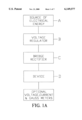
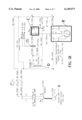
- FIGS. 1A and 1B are schematic block diagrams of the electrical components of the present invention.
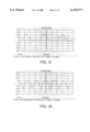
- FIG. 1C is a graph illustrating the half rectified wave form produced by an embodiment of the present invention.
- FIG. 1D is a graph illustrating the fully rectified wave form produced by an embodiment of the present invention.
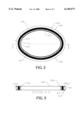
- FIG. 2 is a side view of an embodiment of the present invention showing the relative orientation of the magnetic components and coil component and having a portion of the frame removed for clarity;
- FIG. 3 is a cross-sectional view taken along line A--A of FIG. 2;
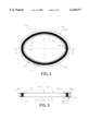
- FIG. 4 is side view of the preferred embodiment of the present invention showing the relative orientation of the coil component and having a portion of the frame removed for clarity;
- FIG. 5 is a cross-sectional view of the preferred embodiment taken along line A--A of FIG. 4;
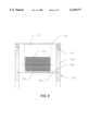
- FIG. 6 is an enlarged sectional view of the portion of the preferred embodiment bounded by the viewing circle of FIG. 5 and further including a cover component;
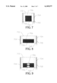
- FIGS. 7-9 are alternate embodiments of the present invention shown in FIG. 6.
- a source of electrical energy preferably 110 or 220 volts in the United States
- An AC transformer designated generally by the reference letter B and labeled "VOLTAGE REGULATOR"
- VOLTAGE REGULATOR is electrically connected to the source A by a conventional power cord preferably rated to handle the input voltage of the source.
- the transformer varies the AC input voltage.
- the AC output is then passed through a single or series of bridge rectifiers C (i.e., labeled as "BRIDGE RECTIFIER").
- the bridge rectifier(s) preferably provide either a full wave or half wave rectification of the wave form to a 60 or 120 cycles per second DC "positive” (i.e., above the reference line on a sinusoidal oscilloscope) wave form.
- the fully rectified wave form from the bridge rectifier(s) is then passed to the free ends of the coil designated generally by the reference letter D and labeled "DEVICE" for convenience.
- FIGS. 1C and 1D are graphs illustrating the half rectified and fully rectified, respectively, wave form produced by an eight hundred (800) winding embodiment of the present invention.
- the sample graphs were taken when the field strength within the confines of the embodiment tested was set to produce 7.5 amps of current.
- an embodiment of the device component of the present invention is designated generally by the reference number 600.
- a portion of the device frame 602 has been partially removed from FIG. 2 in order to show the permanent magnets 604 and the interiorly wrapped coil 606 in their preferred orientation.
- the coil winding 606 overlies the belt or annular layer of permanent magnets 604.
- a cover 610 is provided as a means of protecting and shielding the coil 606 during operation.
- thermocouple type which measure and indicate the coil temperature at various points.
- Cover 610 can be a section of raceway cover which includes a cooperating tongue and groove snap connection 612 so that the cover may be removed to service the interior magnetic and/or coil components of the device.
- the existence of the cover attached to the device frame 602 and the disposition of the magnet and/or coil establish an air space 614 (FIG. 3) between the frame 602, coil 606 and cover 610.
- the air space 614 provides a means of convective heat transfer such that if an air flow in the air space 614 were created, the flow of air would have a tendency to cool the coil 606 and magnets 604 when they become heated after the coil 606 in energized in the manner described below.
- Cross-section line A--A which also serves as a vertical axis and horizontal line L, which serves as a horizontal axis, define the centroid of the interior channel 620 of the device.
- Embodiment 700 includes a frame component 702.
- the side plates 704 cover the coil 706 as it is wrapped around the frame 702.
- One of the side plates has been removed from FIG. 2 for visual clarity of the coil 706 but the side plates 704 are preferably rigidly attached to the frame 702 in a working embodiment of the invention.
- thermocouple 704 Within the coil assembly 704 are a plurality of optional thermal sensors 708, of either the resistance or thermocouple type.
- the sensors are provided as a way of measuring the coil temperature at various points but do not affect the operation of the invention and its useful effect (i.e., angiogenesis and growth retardation of cancerous tumors).
- a cover 710 is preferably rigidly secured to the frame. Attachment of the cover 710 to the frame 702 in the manner shown in the figures creates an air space 714 between the coil 706 and cover 710.
- the cover 710 may be snapped in place by a snap fit cooperation of the cover and the frame 712, or in the alternative the cover may be rigidly and securely attached by numerous others means of securement.
- the air space 714 allows for convective heat transfer from the coil 706 to the air within the air space 714. If an air flow is induced in the air space 714, the flow of air would have a tendency to cool the coil 706 if it heats up during use.
- Cross-section line A--A of FIG. 4 which also serves as a vertical axis V intersects the horizontal axis H to define an approximate interior centroid of the interior 716 of the device (FIG. 4).
- FIGS. 7-9 illustrate a variety of device profiles in order to demonstrate the various configurations the coil 706 may have depending upon the width of the frame. As shown in FIGS. 6 and 9, the device may also multiple coils 706 in a stacked or adjacent relationship as denoted by the hypothetical dashed dividing line of those figures. An optimum coil thickness with respect to width is believed to help establish a more uniform minimum heat generation within the coil 706.
- the following example provides actual data obtained from three (3) independent tests in human to determine if the inventive device and method are useful for relieving pain associated with degenerative diseases and disorders.
- the summary of the data and results is set forth below.
- the data illustrates a before and after pain rating for the various study participants. Some of the twenty nine (29) participants indicated having pain in more than one location of their body. Each participant completed the baseline (i.e., pre-treatment) tests, treatment, and follow-up phases of the study.
- the magnetic field exposure data and pain relief data was systematically collected, tabulated and is set forth below in the tables.
- the apparatus and method of the present invention were found to be useful for relieving pain associated with degenerative diseases and disorders.
Abstract
Description
                                  TABLE 1
__________________________________________________________________________
Estimated Cumulative Magnetic Field Strength Exposure Over 4 to 6 Days
CHIEF    TOTAL #    % Relief
COMPLAINT
         OF    % Relief
                    Evening
                         % Relief
                              % Relief
                                   % Relief
                                        % Relief
CATEGORY SUBJECTS
               After Exp.
                    After Exp.
                         Follow-up
                              0%   <30% >30%
__________________________________________________________________________
Back     7     6    6    4    0    3    4
Leg      8     5    5    5    0    2    6
Knee     3     3    3    3    0    1    2
Neck and Shoulder
         3     3    3    3    0    1    2
TMJ Disorder
         3     3    3    3    0    0    3
Plantar Fascitis
         2     2    2    2    0    1    1
Fibromyalgia Gp. 1
         6     2    2    3    2    3    1
Fibromyalgia Gp. 2
         2     2    2    2    0    0    2
__________________________________________________________________________
                                  TABLE 2
__________________________________________________________________________
Summary of the Results from % Pain Relief - Treatment and Follow-up
Phases of the Study
CHIEF                   Exposure
                             Exposure
                                  Cumulative
COMPLAINT
         Total # of
              Exposures
                   Number of
                        Time Level
                                  Exposure
CATEGORY Subjects
              Per Day
                   Days (minutes)
                             (Gauss)
                                  (Gauss)
__________________________________________________________________________
Back     7    6    4    30   160  19,200
Leg      8    5    4    30   160  19,200
Knee     3    3    4    30   160  19,200
Neck and Shoulder
         3    3    4    30   160  19,200
TMJ Disorder
         3    3    4    30   160  19,200
Plantar Fascitis
         2    2    4    30   160  19,200
Fibromyalgia Gp. 1
         6    2    6    30   110  19,800
Fibromyalgia Gp. 2
         2    2    6    30   160  28,800
__________________________________________________________________________
Claims (20)
Priority Applications (1)
| Application Number | Priority Date | Filing Date | Title |
|---|---|---|---|
| US09/271,884 US6149577A (en) | 1999-03-18 | 1999-03-18 | Apparatus and method for creating a substantially contained, finite magnetic field useful for relieving the symptoms pain and discomfort associated with degenerative diseases and disorders in mammals |
Applications Claiming Priority (1)
| Application Number | Priority Date | Filing Date | Title |
|---|---|---|---|
| US09/271,884 US6149577A (en) | 1999-03-18 | 1999-03-18 | Apparatus and method for creating a substantially contained, finite magnetic field useful for relieving the symptoms pain and discomfort associated with degenerative diseases and disorders in mammals |
Publications (1)
| Publication Number | Publication Date |
|---|---|
| US6149577A true US6149577A (en) | 2000-11-21 |
Family
ID=23037497
Family Applications (1)
| Application Number | Title | Priority Date | Filing Date |
|---|---|---|---|
| US09/271,884 Expired - Lifetime US6149577A (en) | 1999-03-18 | 1999-03-18 | Apparatus and method for creating a substantially contained, finite magnetic field useful for relieving the symptoms pain and discomfort associated with degenerative diseases and disorders in mammals |
Country Status (1)
| Country | Link |
|---|---|
| US (1) | US6149577A (en) |
Cited By (38)
| Publication number | Priority date | Publication date | Assignee | Title |
|---|---|---|---|---|
| US6443882B1 (en) * | 1998-07-08 | 2002-09-03 | Emf Therapeutics, Inc. | Apparatus and method for creating a biologically useful magnetic field |
| US6638241B2 (en) * | 2002-01-03 | 2003-10-28 | Israel Yerushalmy | Apparatus for treating bruxism |
| WO2004016316A1 (en) * | 2002-08-16 | 2004-02-26 | Admetec Co., Ltd. | Heating method and heating apparatus therefor |
| US20050159638A1 (en) * | 2000-09-29 | 2005-07-21 | Delisle Clarence A. | Method and device for treating body ailments |
| US20050267355A1 (en) * | 2004-05-27 | 2005-12-01 | Parker Richard F | Method and apparatus for generating a therapeutic magetic field |
| US20060187607A1 (en) * | 2003-03-31 | 2006-08-24 | Seung-Kee Mo | Apparatus and method for creating pulse magnetic stimulation having modulation function |
| US20070015951A1 (en) * | 2005-07-14 | 2007-01-18 | Culhane Jeffrey J | Bone growth stimulator |
| AU2003207944B2 (en) * | 2002-01-03 | 2007-04-05 | Israel Yerushalmy | Apparatus for treating bruxism |
| US20070078292A1 (en) * | 2005-10-05 | 2007-04-05 | Electromagnetic Resources, Inc. | Electromagnetic fields for systemic effect in therapy |
| US20070083237A1 (en) * | 2005-10-12 | 2007-04-12 | Teruel Elberto B | Magnetic therapeutic device and method of using the same |
| US20070204811A1 (en) * | 2006-03-06 | 2007-09-06 | Agee George S | Therapeutic pet collar |
| US20080097141A1 (en) * | 2006-10-19 | 2008-04-24 | Stanley Kolt | K-ring electromagnetic treatment apparatus, system and method for tumors, arthritis and other ailments |
| US20090234243A1 (en) * | 2004-04-09 | 2009-09-17 | Schneider M Bret | Robotic apparatus for targeting and producing deep, focused transcranial magnetic stimulation |
| US20100185042A1 (en) * | 2007-08-05 | 2010-07-22 | Schneider M Bret | Control and coordination of transcranial magnetic stimulation electromagnets for modulation of deep brain targets |
| US20100286468A1 (en) * | 2007-10-26 | 2010-11-11 | David J Mishelevich | Transcranial magnetic stimulation with protection of magnet-adjacent structures |
| US20110077452A1 (en) * | 2006-10-19 | 2011-03-31 | Stanley Kolt | K-ring electromagnetic treatment apparatus, system and method for tumors, arthritis and other ailments |
| US20110082326A1 (en) * | 2004-04-09 | 2011-04-07 | Mishelevich David J | Treatment of clinical applications with neuromodulation |
| US8343027B1 (en) | 2012-01-30 | 2013-01-01 | Ivivi Health Sciences, Llc | Methods and devices for providing electromagnetic treatment in the presence of a metal-containing implant |
| US8415123B2 (en) | 2004-04-19 | 2013-04-09 | Ivivi Health Sciences, Llc | Electromagnetic treatment apparatus and method for angiogenesis modulation of living tissues and cells |
| US8523753B2 (en) | 2007-11-27 | 2013-09-03 | Cervel Neurotech, Inc. | Transcranial magnet stimulation of deep brain targets |
| US8723628B2 (en) | 2009-01-07 | 2014-05-13 | Cervel Neurotech, Inc. | Shaped coils for transcranial magnetic stimulation |
| US8795148B2 (en) | 2009-10-26 | 2014-08-05 | Cervel Neurotech, Inc. | Sub-motor-threshold stimulation of deep brain targets using transcranial magnetic stimulation |
| US8956274B2 (en) | 2007-08-05 | 2015-02-17 | Cervel Neurotech, Inc. | Transcranial magnetic stimulation field shaping |
| US8956273B2 (en) | 2007-08-20 | 2015-02-17 | Cervel Neurotech, Inc. | Firing patterns for deep brain transcranial magnetic stimulation |
| US8961385B2 (en) | 2003-12-05 | 2015-02-24 | Ivivi Health Sciences, Llc | Devices and method for treatment of degenerative joint diseases with electromagnetic fields |
| US9259343B2 (en) | 2012-07-06 | 2016-02-16 | Newman Technologies LLC | Device for mitigating plantar fasciitis |
| US9320913B2 (en) | 2014-04-16 | 2016-04-26 | Rio Grande Neurosciences, Inc. | Two-part pulsed electromagnetic field applicator for application of therapeutic energy |
| US9352167B2 (en) | 2006-05-05 | 2016-05-31 | Rio Grande Neurosciences, Inc. | Enhanced spatial summation for deep-brain transcranial magnetic stimulation |
| US9415233B2 (en) | 2003-12-05 | 2016-08-16 | Rio Grande Neurosciences, Inc. | Apparatus and method for electromagnetic treatment of neurological pain |
| US9427598B2 (en) | 2010-10-01 | 2016-08-30 | Rio Grande Neurosciences, Inc. | Method and apparatus for electromagnetic treatment of head, cerebral and neural injury in animals and humans |
| US9433797B2 (en) | 2003-12-05 | 2016-09-06 | Rio Grande Neurosciences, Inc. | Apparatus and method for electromagnetic treatment of neurodegenerative conditions |
| US9440089B2 (en) | 2003-12-05 | 2016-09-13 | Rio Grande Neurosciences, Inc. | Apparatus and method for electromagnetic treatment of neurological injury or condition caused by a stroke |
| US9486639B2 (en) | 2006-05-05 | 2016-11-08 | The Board Of Trustees Of The Leland Stanford Junior University | Trajectory-based deep-brain stereotactic transcranial magnetic stimulation |
| US9492679B2 (en) | 2010-07-16 | 2016-11-15 | Rio Grande Neurosciences, Inc. | Transcranial magnetic stimulation for altering susceptibility of tissue to pharmaceuticals and radiation |
| US9656096B2 (en) | 2003-12-05 | 2017-05-23 | Rio Grande Neurosciences, Inc. | Method and apparatus for electromagnetic enhancement of biochemical signaling pathways for therapeutics and prophylaxis in plants, animals and humans |
| US10350428B2 (en) | 2014-11-04 | 2019-07-16 | Endonovo Therapetics, Inc. | Method and apparatus for electromagnetic treatment of living systems |
| US10806942B2 (en) | 2016-11-10 | 2020-10-20 | Qoravita LLC | System and method for applying a low frequency magnetic field to biological tissues |
| US10967194B2 (en) | 2018-05-02 | 2021-04-06 | Shealy-Sorin Wellness, Llc | Pulsed electromagnetic field device and methods of use |
Citations (81)
| Publication number | Priority date | Publication date | Assignee | Title |
|---|---|---|---|---|
| US32947A (en) * | 1861-07-30 | Machine for bending fifth-wheels fob | ||
| US96044A (en) * | 1869-10-19 | Improvement in galvanic apparatus | ||
| US703989A (en) * | 1900-05-08 | 1902-07-08 | Max Wyler | Magneto-therapeutic apparatus. |
| US770433A (en) * | 1904-09-20 | Thermal inductor | ||
| US781448A (en) * | 1904-10-29 | 1905-01-31 | John Mcintyre | Electromagnetic apparatus. |
| US2102790A (en) * | 1934-08-20 | 1937-12-21 | Howard B Drollinger | Therapeutic apparatus |
| US3570476A (en) * | 1968-11-18 | 1971-03-16 | David Paul Gregg | Magnetostrictive medical instrument |
| US3890953A (en) * | 1971-04-06 | 1975-06-24 | Werner Kraus | Electrical apparatus generating a low frequency, alternating magnetic field for promoting the growth of bone and other body tissues |
| US3915151A (en) * | 1973-03-23 | 1975-10-28 | Werner Kraus | Apparatus for promoting healing processes |
| US4066065A (en) * | 1974-07-04 | 1978-01-03 | Werner Kraus | Coil structure for electromagnetic therapy |
| US4134395A (en) * | 1976-12-29 | 1979-01-16 | Biomagnetics International, Inc. | Method of using magnetic fields to conduct a screening diagnostic examination |
| US4233965A (en) * | 1978-01-16 | 1980-11-18 | Cas Products, Inc. | Method and apparatus for the therapeutic treatment of living tissue |
| US4303636A (en) * | 1974-08-20 | 1981-12-01 | Gordon Robert T | Cancer treatment |
| EP0048451A1 (en) * | 1980-09-24 | 1982-03-31 | 121873 Canada Inc. | Electro-magnetic therapeutic system and method |
| US4402309A (en) * | 1981-10-22 | 1983-09-06 | Donald L. Morton & Associates | Therapeutic magnetic electrode |
| EP0181053A2 (en) * | 1984-09-12 | 1986-05-14 | Irt, Inc. | Pulse electro-magnetic field therapy device with auto biased circuit and method for use |
| US4622952A (en) * | 1983-01-13 | 1986-11-18 | Gordon Robert T | Cancer treatment method |
| US4626792A (en) * | 1984-01-10 | 1986-12-02 | Cornell Research Foundation, Inc. | Pure crystal exciton laser amplifier and method of operation |
| US4641633A (en) * | 1982-03-16 | 1987-02-10 | Delgado Jose M R | Electronic system for the activation, inhibition and/or modification of the development and functioning of cells, organs and organisms of living beings |
| US4674482A (en) * | 1984-09-12 | 1987-06-23 | Irt, Inc. | Pulse electro-magnetic field therapy device with auto bias circuit |
| US4765310A (en) * | 1985-11-01 | 1988-08-23 | Dynatens Research Corporation | Electrical and magnetic pain treatment device |
| US4818697A (en) * | 1986-10-27 | 1989-04-04 | Life Resonances, Inc. | Techniques for enhancing the permeability of ions through membranes |
| USRE32947E (en) | 1980-09-30 | 1989-06-13 | Baptist Medical Center Of Oklahoma, Inc. | Magnetic transcutaneous mount for external device of an associated implant |
| US4838850A (en) * | 1980-10-03 | 1989-06-13 | Henning Rosengart | Electromedical treatment apparatus |
| US4889526A (en) * | 1984-08-27 | 1989-12-26 | Magtech Laboratories, Inc. | Non-invasive method and apparatus for modulating brain signals through an external magnetic or electric field to reduce pain |
| EP0371504A2 (en) * | 1988-11-30 | 1990-06-06 | Jerry I. Jacobson | Therapeutic treatment of mammals |
| US4932951A (en) * | 1988-03-23 | 1990-06-12 | Life Resonances, Inc. | Method and apparatus for controlling tissue growth and an applied fluctuating magnetic field |
| US4940453A (en) * | 1987-01-28 | 1990-07-10 | Cadwell Industries, Inc. | Method and apparatus for magnetically stimulating neurons |
| US4993413A (en) * | 1988-09-22 | 1991-02-19 | The Research Foundation Of State University Of New York | Method and apparatus for inducing a current and voltage in living tissue |
| US4994015A (en) * | 1987-09-14 | 1991-02-19 | Cadwell Industries, Inc. | Magnetic stimulator coils |
| US5000178A (en) * | 1986-05-23 | 1991-03-19 | Lti Biomedical, Inc. | Shielded electromagnetic transducer |
| US5010897A (en) * | 1989-04-26 | 1991-04-30 | Leveen Harry H | Apparatus for deep heating of cancer |
| US5014699A (en) * | 1986-05-23 | 1991-05-14 | Trustees Of The University Of Pennsylvania | Electromagnetic method and apparatus for healing living tissue |
| US5030196A (en) * | 1980-04-23 | 1991-07-09 | Inoue-Japax Research Incorporated | Magnetic treatment device |
| US5045050A (en) * | 1989-11-15 | 1991-09-03 | Life Resonances | Method and apparatus for the treatment of cancer |
| US5047005A (en) * | 1987-01-28 | 1991-09-10 | Cadwell Industries, Inc. | Method and apparatus for magnetically stimulating neurons |
| US5061234A (en) * | 1989-09-25 | 1991-10-29 | Corteks, Inc. | Magnetic neural stimulator for neurophysiology |
| US5066272A (en) * | 1990-06-29 | 1991-11-19 | The Johns Hopkins University | Magnetic nerve stimulator |
| US5067940A (en) * | 1988-03-23 | 1991-11-26 | Life Resonances, Inc. | Method and apparatus for controlling the growth of cartilage |
| US5077934A (en) * | 1989-09-22 | 1992-01-07 | Life Resonances, Inc. | Method and apparatus for controlling plant growth |
| US5078674A (en) * | 1989-02-10 | 1992-01-07 | Cadwll Industries, Inc. | Magnetic stimulator coils |
| US5084003A (en) * | 1989-11-24 | 1992-01-28 | Dragan Susic | Magnetic massage therapy device |
| US5085626A (en) * | 1988-12-06 | 1992-02-04 | Alsthom International S.A. | Physiotherapeutic apparatus provided for producing a magnetic field to be used as a therapeutic means |
| US5085627A (en) * | 1988-08-18 | 1992-02-04 | Mezhotraslevoi Nauchno-Tekhnichesky Komplex "Mikrokhirurgia Glaza" | Method for treatment of diseases of the optic tract |
| US5087336A (en) * | 1989-01-09 | 1992-02-11 | Life Resonances, Inc. | Methods and apparatus for regulating transmembrane ion movement utilizing selective harmonic frequencies and simultaneous multiple ion regulation |
| US5088976A (en) * | 1988-03-23 | 1992-02-18 | Life Resonances, Inc. | Deformable magnetic field aiding coils for use in controlling tissue growth |
| US5090423A (en) * | 1988-02-18 | 1992-02-25 | Omron Corporation | Local heating apparatus and cavity resonator for local heating |
| US5100373A (en) * | 1989-01-09 | 1992-03-31 | Life Resonances, Inc. | Techniques for controlling osteoporosis using non-invasive magnetic fields |
| US5106361A (en) * | 1988-03-23 | 1992-04-21 | Life Resonances, Inc. | Method and apparatus for controlling the growth of non-osseous non-cartilaginous solid connective tissue |
| US5116304A (en) * | 1987-01-28 | 1992-05-26 | Cadwell Industries, Inc. | Magnetic stimulator with skullcap-shaped coil |
| US5123898A (en) * | 1988-03-23 | 1992-06-23 | Life Resonances, Inc. | Method and apparatus for controlling tissue growth with an applied fluctuating magnetic field |
| US5131904A (en) * | 1990-05-04 | 1992-07-21 | Richard Markoll | Treatment of arthritis with magnetic field therapy and apparatus therefor |
| US5143588A (en) * | 1986-10-27 | 1992-09-01 | Life Resonances, Inc. | Techniques for enhancing the permeability of ions through membranes |
| US5156587A (en) * | 1983-09-01 | 1992-10-20 | Montone Liber J | Method for treating malignant cells |
| US5160591A (en) * | 1986-10-27 | 1992-11-03 | Life Resonances, Inc. | Methods and apparatus for regulating transmembrane ion movement utilizing selective harmonic frequencies and simultaneous multiple ion regulation |
| US5183456A (en) * | 1989-11-15 | 1993-02-02 | Life Resonances, Inc. | Method and apparatus for the treatment of cancer |
| US5195940A (en) * | 1991-06-20 | 1993-03-23 | Iatromed, Inc. | Method for increased production of growth factor in living tissue using an applied fluctuating magnetic field |
| US5211622A (en) * | 1989-11-15 | 1993-05-18 | Life Resonances, Inc. | Method and apparatus for the treatment of cancer |
| US5215642A (en) * | 1986-10-27 | 1993-06-01 | Life Resonances, Inc. | Improved method and apparatus for regulating transmembrane ion movement |
| US5215633A (en) * | 1986-10-27 | 1993-06-01 | Life Resonances, Inc. | Techniques for enhancing the permeability of ions through membranes |
| US5224922A (en) * | 1988-05-19 | 1993-07-06 | Kurtz Warren H | Quasistatic biological cell and tissue modifier |
| US5267939A (en) * | 1989-01-09 | 1993-12-07 | Life Resonances, Inc. | Techniques for controlling osteoporosis using non-invasive magnetic fields |
| US5269746A (en) * | 1982-12-20 | 1993-12-14 | Jacobson Jerry I | Therapeutic treatment of mammals for epilepsy and Parkinson's disease |
| US5269745A (en) * | 1988-03-23 | 1993-12-14 | Life Resonances, Inc. | Method and apparatus for controlling tissue growth with an applied fluctuating magnetic field |
| US5290409A (en) * | 1986-10-27 | 1994-03-01 | Life Resonances, Inc. | Methods and apparatus for regulating transmembrane ion movement utilizing selective harmonic frequencies and simultaneous multiple ion regulation |
| US5312321A (en) * | 1986-11-21 | 1994-05-17 | Holcomb Technology, Inc. | Method and apparatus for suppressing neuron action potential firings |
| US5314400A (en) * | 1988-04-25 | 1994-05-24 | Tsyb Anatoly F | Device for magnotherapy |
| US5318561A (en) * | 1988-03-23 | 1994-06-07 | Life Resonances Inc. | Deformable magnetic field aiding coils for use in controlling tissue growth |
| US5344384A (en) * | 1992-12-11 | 1994-09-06 | Electromagnetic Bracing Systems, Inc. | Magnetotherapy apparatus |
| US5357958A (en) * | 1993-03-18 | 1994-10-25 | The Regents Of The University Of California | Interventional MRI system and RF coils therefore |
| US5366435A (en) * | 1982-12-20 | 1994-11-22 | Jacobson Jerry I | Therapeutic treatment of mammals |
| US5368544A (en) * | 1990-10-04 | 1994-11-29 | Tn Bio-Electronics Pty. Ltd. | Treatment of living bodies |
| US5415617A (en) * | 1990-05-29 | 1995-05-16 | Kraus; Werner | Applicator coil for magnetic field therapy |
| US5441495A (en) * | 1989-08-17 | 1995-08-15 | Life Resonances, Inc. | Electromagnetic treatment therapy for stroke victim |
| US5476438A (en) * | 1993-03-11 | 1995-12-19 | Zentralinstitut Fur Biomedizinische Technik Universitat Ulm | Method and apparatus for neuromagnetic stimulation |
| US5518495A (en) * | 1994-08-29 | 1996-05-21 | Magnetherapy, Inc. | Magnetic field therapy apparatus |
| US5525949A (en) * | 1991-06-19 | 1996-06-11 | Oxford Instruments (Uk) Ltd. | Energy storage device |
| US5541563A (en) * | 1995-01-11 | 1996-07-30 | The United States Of America As Represented By The Secretary Of The Army | Magnet iron structure |
| US5658234A (en) * | 1995-07-24 | 1997-08-19 | J. D. Technologies, Inc. | Method for treating tumors |
| US5880661A (en) * | 1996-04-01 | 1999-03-09 | Emf Therapeutics, Inc. | Complex magnetic field generating device |
| US6007476A (en) * | 1997-10-22 | 1999-12-28 | Emf Therapeutics, Inc. | Non-particle, non-photonic device and method for affecting angiogenesis |
-
1999
- 1999-03-18 US US09/271,884 patent/US6149577A/en not_active Expired - Lifetime
Patent Citations (92)
| Publication number | Priority date | Publication date | Assignee | Title |
|---|---|---|---|---|
| US32947A (en) * | 1861-07-30 | Machine for bending fifth-wheels fob | ||
| US96044A (en) * | 1869-10-19 | Improvement in galvanic apparatus | ||
| US770433A (en) * | 1904-09-20 | Thermal inductor | ||
| US703989A (en) * | 1900-05-08 | 1902-07-08 | Max Wyler | Magneto-therapeutic apparatus. |
| US781448A (en) * | 1904-10-29 | 1905-01-31 | John Mcintyre | Electromagnetic apparatus. |
| US2102790A (en) * | 1934-08-20 | 1937-12-21 | Howard B Drollinger | Therapeutic apparatus |
| US3570476A (en) * | 1968-11-18 | 1971-03-16 | David Paul Gregg | Magnetostrictive medical instrument |
| US3890953A (en) * | 1971-04-06 | 1975-06-24 | Werner Kraus | Electrical apparatus generating a low frequency, alternating magnetic field for promoting the growth of bone and other body tissues |
| US3915151A (en) * | 1973-03-23 | 1975-10-28 | Werner Kraus | Apparatus for promoting healing processes |
| US4066065A (en) * | 1974-07-04 | 1978-01-03 | Werner Kraus | Coil structure for electromagnetic therapy |
| US4303636A (en) * | 1974-08-20 | 1981-12-01 | Gordon Robert T | Cancer treatment |
| US4134395A (en) * | 1976-12-29 | 1979-01-16 | Biomagnetics International, Inc. | Method of using magnetic fields to conduct a screening diagnostic examination |
| US4233965A (en) * | 1978-01-16 | 1980-11-18 | Cas Products, Inc. | Method and apparatus for the therapeutic treatment of living tissue |
| US5030196A (en) * | 1980-04-23 | 1991-07-09 | Inoue-Japax Research Incorporated | Magnetic treatment device |
| EP0048451A1 (en) * | 1980-09-24 | 1982-03-31 | 121873 Canada Inc. | Electro-magnetic therapeutic system and method |
| USRE32947E (en) | 1980-09-30 | 1989-06-13 | Baptist Medical Center Of Oklahoma, Inc. | Magnetic transcutaneous mount for external device of an associated implant |
| US4838850A (en) * | 1980-10-03 | 1989-06-13 | Henning Rosengart | Electromedical treatment apparatus |
| US4402309A (en) * | 1981-10-22 | 1983-09-06 | Donald L. Morton & Associates | Therapeutic magnetic electrode |
| US4641633A (en) * | 1982-03-16 | 1987-02-10 | Delgado Jose M R | Electronic system for the activation, inhibition and/or modification of the development and functioning of cells, organs and organisms of living beings |
| US5366435A (en) * | 1982-12-20 | 1994-11-22 | Jacobson Jerry I | Therapeutic treatment of mammals |
| US5269746A (en) * | 1982-12-20 | 1993-12-14 | Jacobson Jerry I | Therapeutic treatment of mammals for epilepsy and Parkinson's disease |
| US4622952A (en) * | 1983-01-13 | 1986-11-18 | Gordon Robert T | Cancer treatment method |
| US5156587A (en) * | 1983-09-01 | 1992-10-20 | Montone Liber J | Method for treating malignant cells |
| US4626792A (en) * | 1984-01-10 | 1986-12-02 | Cornell Research Foundation, Inc. | Pure crystal exciton laser amplifier and method of operation |
| US4889526A (en) * | 1984-08-27 | 1989-12-26 | Magtech Laboratories, Inc. | Non-invasive method and apparatus for modulating brain signals through an external magnetic or electric field to reduce pain |
| US4674482A (en) * | 1984-09-12 | 1987-06-23 | Irt, Inc. | Pulse electro-magnetic field therapy device with auto bias circuit |
| EP0181053A2 (en) * | 1984-09-12 | 1986-05-14 | Irt, Inc. | Pulse electro-magnetic field therapy device with auto biased circuit and method for use |
| US4765310A (en) * | 1985-11-01 | 1988-08-23 | Dynatens Research Corporation | Electrical and magnetic pain treatment device |
| US5000178A (en) * | 1986-05-23 | 1991-03-19 | Lti Biomedical, Inc. | Shielded electromagnetic transducer |
| US5014699A (en) * | 1986-05-23 | 1991-05-14 | Trustees Of The University Of Pennsylvania | Electromagnetic method and apparatus for healing living tissue |
| US5312534A (en) * | 1986-10-27 | 1994-05-17 | Liboff Abraham R | Techniques for enhancing the permeability of ions through membranes |
| US4818697A (en) * | 1986-10-27 | 1989-04-04 | Life Resonances, Inc. | Techniques for enhancing the permeability of ions through membranes |
| US5143588A (en) * | 1986-10-27 | 1992-09-01 | Life Resonances, Inc. | Techniques for enhancing the permeability of ions through membranes |
| US5290409A (en) * | 1986-10-27 | 1994-03-01 | Life Resonances, Inc. | Methods and apparatus for regulating transmembrane ion movement utilizing selective harmonic frequencies and simultaneous multiple ion regulation |
| US5160591A (en) * | 1986-10-27 | 1992-11-03 | Life Resonances, Inc. | Methods and apparatus for regulating transmembrane ion movement utilizing selective harmonic frequencies and simultaneous multiple ion regulation |
| US5215642A (en) * | 1986-10-27 | 1993-06-01 | Life Resonances, Inc. | Improved method and apparatus for regulating transmembrane ion movement |
| US5059298A (en) * | 1986-10-27 | 1991-10-22 | Life Resonances, Inc. | Method and apparatus for regulating transmembrane ion movement |
| US5215633A (en) * | 1986-10-27 | 1993-06-01 | Life Resonances, Inc. | Techniques for enhancing the permeability of ions through membranes |
| US5312321A (en) * | 1986-11-21 | 1994-05-17 | Holcomb Technology, Inc. | Method and apparatus for suppressing neuron action potential firings |
| US5047005A (en) * | 1987-01-28 | 1991-09-10 | Cadwell Industries, Inc. | Method and apparatus for magnetically stimulating neurons |
| US4940453A (en) * | 1987-01-28 | 1990-07-10 | Cadwell Industries, Inc. | Method and apparatus for magnetically stimulating neurons |
| US5116304A (en) * | 1987-01-28 | 1992-05-26 | Cadwell Industries, Inc. | Magnetic stimulator with skullcap-shaped coil |
| US4994015A (en) * | 1987-09-14 | 1991-02-19 | Cadwell Industries, Inc. | Magnetic stimulator coils |
| US5090423A (en) * | 1988-02-18 | 1992-02-25 | Omron Corporation | Local heating apparatus and cavity resonator for local heating |
| US5088976A (en) * | 1988-03-23 | 1992-02-18 | Life Resonances, Inc. | Deformable magnetic field aiding coils for use in controlling tissue growth |
| US5318561A (en) * | 1988-03-23 | 1994-06-07 | Life Resonances Inc. | Deformable magnetic field aiding coils for use in controlling tissue growth |
| US4932951A (en) * | 1988-03-23 | 1990-06-12 | Life Resonances, Inc. | Method and apparatus for controlling tissue growth and an applied fluctuating magnetic field |
| US5269745A (en) * | 1988-03-23 | 1993-12-14 | Life Resonances, Inc. | Method and apparatus for controlling tissue growth with an applied fluctuating magnetic field |
| US5067940A (en) * | 1988-03-23 | 1991-11-26 | Life Resonances, Inc. | Method and apparatus for controlling the growth of cartilage |
| US5106361A (en) * | 1988-03-23 | 1992-04-21 | Life Resonances, Inc. | Method and apparatus for controlling the growth of non-osseous non-cartilaginous solid connective tissue |
| US5518496A (en) * | 1988-03-23 | 1996-05-21 | Life Resonances, Inc. | Deformable magnetic field aiding coils for use in controlling tissue growth |
| US5123898A (en) * | 1988-03-23 | 1992-06-23 | Life Resonances, Inc. | Method and apparatus for controlling tissue growth with an applied fluctuating magnetic field |
| US5458558A (en) * | 1988-03-23 | 1995-10-17 | Life Resonances, Inc. | Method for controlling tissue growth with an applied fluctuating magnetic field |
| US5314400A (en) * | 1988-04-25 | 1994-05-24 | Tsyb Anatoly F | Device for magnotherapy |
| US5224922A (en) * | 1988-05-19 | 1993-07-06 | Kurtz Warren H | Quasistatic biological cell and tissue modifier |
| US5085627A (en) * | 1988-08-18 | 1992-02-04 | Mezhotraslevoi Nauchno-Tekhnichesky Komplex "Mikrokhirurgia Glaza" | Method for treatment of diseases of the optic tract |
| US4993413A (en) * | 1988-09-22 | 1991-02-19 | The Research Foundation Of State University Of New York | Method and apparatus for inducing a current and voltage in living tissue |
| EP0371504A2 (en) * | 1988-11-30 | 1990-06-06 | Jerry I. Jacobson | Therapeutic treatment of mammals |
| US5085626A (en) * | 1988-12-06 | 1992-02-04 | Alsthom International S.A. | Physiotherapeutic apparatus provided for producing a magnetic field to be used as a therapeutic means |
| US5087336A (en) * | 1989-01-09 | 1992-02-11 | Life Resonances, Inc. | Methods and apparatus for regulating transmembrane ion movement utilizing selective harmonic frequencies and simultaneous multiple ion regulation |
| US5100373A (en) * | 1989-01-09 | 1992-03-31 | Life Resonances, Inc. | Techniques for controlling osteoporosis using non-invasive magnetic fields |
| US5267939A (en) * | 1989-01-09 | 1993-12-07 | Life Resonances, Inc. | Techniques for controlling osteoporosis using non-invasive magnetic fields |
| US5078674A (en) * | 1989-02-10 | 1992-01-07 | Cadwll Industries, Inc. | Magnetic stimulator coils |
| US5010897A (en) * | 1989-04-26 | 1991-04-30 | Leveen Harry H | Apparatus for deep heating of cancer |
| US5441495A (en) * | 1989-08-17 | 1995-08-15 | Life Resonances, Inc. | Electromagnetic treatment therapy for stroke victim |
| US5077934A (en) * | 1989-09-22 | 1992-01-07 | Life Resonances, Inc. | Method and apparatus for controlling plant growth |
| US5061234A (en) * | 1989-09-25 | 1991-10-29 | Corteks, Inc. | Magnetic neural stimulator for neurophysiology |
| US5183456A (en) * | 1989-11-15 | 1993-02-02 | Life Resonances, Inc. | Method and apparatus for the treatment of cancer |
| US5045050A (en) * | 1989-11-15 | 1991-09-03 | Life Resonances | Method and apparatus for the treatment of cancer |
| US5211622A (en) * | 1989-11-15 | 1993-05-18 | Life Resonances, Inc. | Method and apparatus for the treatment of cancer |
| US5437600A (en) * | 1989-11-15 | 1995-08-01 | Life Resonances, Inc. | Method and apparatus for the treatment of cancer |
| US5084003A (en) * | 1989-11-24 | 1992-01-28 | Dragan Susic | Magnetic massage therapy device |
| US5842966A (en) * | 1990-05-04 | 1998-12-01 | Bio-Magnetic Therapy Systems, Inc. | Treatment of arthritis with magnetic field therapy |
| US5387176A (en) * | 1990-05-04 | 1995-02-07 | Bio-Magnetic Therapy Systems Inc. | Treatment of acute diseases as caused by the sports-type injuries of the musculoskeletal system excluding fractures with magnetic field therapy |
| US5669868A (en) * | 1990-05-04 | 1997-09-23 | Bio-Magnetic Therapy Systems | Treatment of wrinkled discolored or aging skin with magnetic field therapy |
| US5665049A (en) * | 1990-05-04 | 1997-09-09 | Bio-Magnetic Field Therapy Systems Inc. | Treatment of acute diseases as caused by the sports-type injuries of the musculoskeletal system (excluding fractures) with magnetic field therapy |
| US5453073A (en) * | 1990-05-04 | 1995-09-26 | Bio Magnetic Therapy Sys Inc | Apparatus for treatment of diseased body organs with magnetic field therapy |
| US5131904A (en) * | 1990-05-04 | 1992-07-21 | Richard Markoll | Treatment of arthritis with magnetic field therapy and apparatus therefor |
| US5415617A (en) * | 1990-05-29 | 1995-05-16 | Kraus; Werner | Applicator coil for magnetic field therapy |
| US5066272A (en) * | 1990-06-29 | 1991-11-19 | The Johns Hopkins University | Magnetic nerve stimulator |
| US5368544A (en) * | 1990-10-04 | 1994-11-29 | Tn Bio-Electronics Pty. Ltd. | Treatment of living bodies |
| US5525949A (en) * | 1991-06-19 | 1996-06-11 | Oxford Instruments (Uk) Ltd. | Energy storage device |
| US5330410A (en) * | 1991-06-20 | 1994-07-19 | Iatromed, Inc. | Method for increased production of growth factor in living tissue using an applied fluctuating magnetic field |
| US5195940A (en) * | 1991-06-20 | 1993-03-23 | Iatromed, Inc. | Method for increased production of growth factor in living tissue using an applied fluctuating magnetic field |
| US5344384A (en) * | 1992-12-11 | 1994-09-06 | Electromagnetic Bracing Systems, Inc. | Magnetotherapy apparatus |
| US5476438A (en) * | 1993-03-11 | 1995-12-19 | Zentralinstitut Fur Biomedizinische Technik Universitat Ulm | Method and apparatus for neuromagnetic stimulation |
| US5357958A (en) * | 1993-03-18 | 1994-10-25 | The Regents Of The University Of California | Interventional MRI system and RF coils therefore |
| US5518495A (en) * | 1994-08-29 | 1996-05-21 | Magnetherapy, Inc. | Magnetic field therapy apparatus |
| US5541563A (en) * | 1995-01-11 | 1996-07-30 | The United States Of America As Represented By The Secretary Of The Army | Magnet iron structure |
| US5658234A (en) * | 1995-07-24 | 1997-08-19 | J. D. Technologies, Inc. | Method for treating tumors |
| US5880661A (en) * | 1996-04-01 | 1999-03-09 | Emf Therapeutics, Inc. | Complex magnetic field generating device |
| US6007476A (en) * | 1997-10-22 | 1999-12-28 | Emf Therapeutics, Inc. | Non-particle, non-photonic device and method for affecting angiogenesis |
Non-Patent Citations (14)
| Title |
|---|
| Abstract and Article: Journal of Cellular Physiology 134:37 45 (1988); Yen Patton, et al., Endothelial Cell Response to Pulsed Electromagnetic Fields: Stimulation of Growth Rate and Angiogenesis in Vitro . * |
| Abstract and Article: Journal of Cellular Physiology 134:37-45 (1988); Yen-Patton, et al., "Endothelial Cell Response to Pulsed Electromagnetic Fields: Stimulation of Growth Rate and Angiogenesis in Vitro". |
| Bone, vol. 19, No. 1 Supplement, Jul. 1996, pp. 39S 57S, by H. Winet, The Role of Microvasculature in Normal and Perturbed Bone Healing as Revealed by Intravital Microscopy . * |
| Bone, vol. 19, No. 1 Supplement, Jul. 1996, pp. 39S-57S, by H. Winet, "The Role of Microvasculature in Normal and Perturbed Bone Healing as Revealed by Intravital Microscopy". |
| Chemical Abstracts, vol. 124, No. 3, Jan. 15, 1996, Robins, H. Ian et al.; "Cytokine induction by 41.8 degree C whole body hyperthermia". |
| Chemical Abstracts, vol. 124, No. 3, Jan. 15, 1996, Robins, H. Ian et al.; Cytokine induction by 41.8 degree C whole body hyperthermia . * |
| Chemical Abstracts, vol. 128, No. 14 Apr. 6, 1998, Ikeda, Shigeki et al.; "Enhancement of the effect of an angiogenesis inhibitor on murine tumors by hypothermia". |
| Chemical Abstracts, vol. 128, No. 14 Apr. 6, 1998, Ikeda, Shigeki et al.; Enhancement of the effect of an angiogenesis inhibitor on murine tumors by hypothermia . * |
| Guterl, Fred; "Beauty and Magnets"; Discover Magazine, Mar. 1997 pp. 38-43. |
| Guterl, Fred; Beauty and Magnets ; Discover Magazine, Mar. 1997 pp. 38 43. * |
| O Brien, Jim; Revolutionary New Magnetic Therapy Kos Arthritis Pain , Your Health Magazine, Apr. 6, 1993, pp. 17 18. * |
| O'Brien, Jim; "Revolutionary New Magnetic Therapy Kos Arthritis Pain", Your Health Magazine, Apr. 6, 1993, pp. 17-18. |
| Proceeding Abstract of the 4 th EBEA Congress, Zagreb, Croatia, Nov. 19 21, 1998; G. Sersa et al., Tumour Blood Flow Changes Induced by Application of Electric Pulses . * |
| Proceeding Abstract of the 4th EBEA Congress, Zagreb, Croatia, Nov. 19-21, 1998; G. Sersa et al., "Tumour Blood Flow Changes Induced by Application of Electric Pulses". |
Cited By (53)
| Publication number | Priority date | Publication date | Assignee | Title |
|---|---|---|---|---|
| US6443882B1 (en) * | 1998-07-08 | 2002-09-03 | Emf Therapeutics, Inc. | Apparatus and method for creating a biologically useful magnetic field |
| US20050159638A1 (en) * | 2000-09-29 | 2005-07-21 | Delisle Clarence A. | Method and device for treating body ailments |
| US7963904B2 (en) * | 2000-09-29 | 2011-06-21 | Delisle Clarence A | Method and device for treating body ailments |
| US6638241B2 (en) * | 2002-01-03 | 2003-10-28 | Israel Yerushalmy | Apparatus for treating bruxism |
| AU2003207944B2 (en) * | 2002-01-03 | 2007-04-05 | Israel Yerushalmy | Apparatus for treating bruxism |
| WO2004016316A1 (en) * | 2002-08-16 | 2004-02-26 | Admetec Co., Ltd. | Heating method and heating apparatus therefor |
| US20060187607A1 (en) * | 2003-03-31 | 2006-08-24 | Seung-Kee Mo | Apparatus and method for creating pulse magnetic stimulation having modulation function |
| US10207122B2 (en) | 2003-12-05 | 2019-02-19 | Endonovo Therapeutics, Inc. | Method and apparatus for electromagnetic enhancement of biochemical signaling pathways for therapeutics and prophylaxis in plants, animals and humans |
| US9415233B2 (en) | 2003-12-05 | 2016-08-16 | Rio Grande Neurosciences, Inc. | Apparatus and method for electromagnetic treatment of neurological pain |
| US9433797B2 (en) | 2003-12-05 | 2016-09-06 | Rio Grande Neurosciences, Inc. | Apparatus and method for electromagnetic treatment of neurodegenerative conditions |
| US9440089B2 (en) | 2003-12-05 | 2016-09-13 | Rio Grande Neurosciences, Inc. | Apparatus and method for electromagnetic treatment of neurological injury or condition caused by a stroke |
| US8961385B2 (en) | 2003-12-05 | 2015-02-24 | Ivivi Health Sciences, Llc | Devices and method for treatment of degenerative joint diseases with electromagnetic fields |
| US10226640B2 (en) | 2003-12-05 | 2019-03-12 | Endonovo Therapeutics, Inc. | Devices and method for treatment of degenerative joint diseases with electromagnetic fields |
| US9656096B2 (en) | 2003-12-05 | 2017-05-23 | Rio Grande Neurosciences, Inc. | Method and apparatus for electromagnetic enhancement of biochemical signaling pathways for therapeutics and prophylaxis in plants, animals and humans |
| US20110082326A1 (en) * | 2004-04-09 | 2011-04-07 | Mishelevich David J | Treatment of clinical applications with neuromodulation |
| US20090234243A1 (en) * | 2004-04-09 | 2009-09-17 | Schneider M Bret | Robotic apparatus for targeting and producing deep, focused transcranial magnetic stimulation |
| US8845508B2 (en) | 2004-04-09 | 2014-09-30 | The Board Of Trustees Of The Leland Stanford Junior University | Robotic apparatus for targeting and producing deep, focused transcranial magnetic stimulation |
| US8415123B2 (en) | 2004-04-19 | 2013-04-09 | Ivivi Health Sciences, Llc | Electromagnetic treatment apparatus and method for angiogenesis modulation of living tissues and cells |
| US20050267355A1 (en) * | 2004-05-27 | 2005-12-01 | Parker Richard F | Method and apparatus for generating a therapeutic magetic field |
| US7361136B2 (en) | 2004-05-27 | 2008-04-22 | Parker Richard F | Method and apparatus for generating a therapeutic magnetic field |
| US7465269B2 (en) | 2005-07-14 | 2008-12-16 | Djo, Llc | Bone growth stimulator |
| US20090163761A1 (en) * | 2005-07-14 | 2009-06-25 | Djo, Llc | Bone growth stimulator |
| US20070015951A1 (en) * | 2005-07-14 | 2007-01-18 | Culhane Jeffrey J | Bone growth stimulator |
| US8496570B2 (en) | 2005-07-14 | 2013-07-30 | Djo, Llc | Bone growth stimulator |
| EP1945295A4 (en) * | 2005-10-05 | 2010-12-01 | Electromagnetic Resources Inc | Electromagnetic fields for systemic effect in therapy |
| US20070078292A1 (en) * | 2005-10-05 | 2007-04-05 | Electromagnetic Resources, Inc. | Electromagnetic fields for systemic effect in therapy |
| EP1945295A2 (en) * | 2005-10-05 | 2008-07-23 | Electromagnetic Resources Inc. | Electromagnetic fields for systemic effect in therapy |
| US20070083237A1 (en) * | 2005-10-12 | 2007-04-12 | Teruel Elberto B | Magnetic therapeutic device and method of using the same |
| US20070204811A1 (en) * | 2006-03-06 | 2007-09-06 | Agee George S | Therapeutic pet collar |
| US9486639B2 (en) | 2006-05-05 | 2016-11-08 | The Board Of Trustees Of The Leland Stanford Junior University | Trajectory-based deep-brain stereotactic transcranial magnetic stimulation |
| US9352167B2 (en) | 2006-05-05 | 2016-05-31 | Rio Grande Neurosciences, Inc. | Enhanced spatial summation for deep-brain transcranial magnetic stimulation |
| US8602960B2 (en) * | 2006-10-19 | 2013-12-10 | Stanley Kolt | K-Ring electromagnetic treatment apparatus, system and method for tumors, arthritis and other ailments |
| US20110077452A1 (en) * | 2006-10-19 | 2011-03-31 | Stanley Kolt | K-ring electromagnetic treatment apparatus, system and method for tumors, arthritis and other ailments |
| US20080097141A1 (en) * | 2006-10-19 | 2008-04-24 | Stanley Kolt | K-ring electromagnetic treatment apparatus, system and method for tumors, arthritis and other ailments |
| US8956274B2 (en) | 2007-08-05 | 2015-02-17 | Cervel Neurotech, Inc. | Transcranial magnetic stimulation field shaping |
| US20100185042A1 (en) * | 2007-08-05 | 2010-07-22 | Schneider M Bret | Control and coordination of transcranial magnetic stimulation electromagnets for modulation of deep brain targets |
| US8956273B2 (en) | 2007-08-20 | 2015-02-17 | Cervel Neurotech, Inc. | Firing patterns for deep brain transcranial magnetic stimulation |
| US20100286468A1 (en) * | 2007-10-26 | 2010-11-11 | David J Mishelevich | Transcranial magnetic stimulation with protection of magnet-adjacent structures |
| US8523753B2 (en) | 2007-11-27 | 2013-09-03 | Cervel Neurotech, Inc. | Transcranial magnet stimulation of deep brain targets |
| US9132277B2 (en) | 2009-01-07 | 2015-09-15 | Cerval Neurotech, Inc. | Shaped coils for transcranial magnetic stimulation |
| US9381374B2 (en) | 2009-01-07 | 2016-07-05 | Rio Grande Neurosciences, Inc. | Shaped coils for transcranial magnetic stimulation |
| US8723628B2 (en) | 2009-01-07 | 2014-05-13 | Cervel Neurotech, Inc. | Shaped coils for transcranial magnetic stimulation |
| US8795148B2 (en) | 2009-10-26 | 2014-08-05 | Cervel Neurotech, Inc. | Sub-motor-threshold stimulation of deep brain targets using transcranial magnetic stimulation |
| US9492679B2 (en) | 2010-07-16 | 2016-11-15 | Rio Grande Neurosciences, Inc. | Transcranial magnetic stimulation for altering susceptibility of tissue to pharmaceuticals and radiation |
| US9427598B2 (en) | 2010-10-01 | 2016-08-30 | Rio Grande Neurosciences, Inc. | Method and apparatus for electromagnetic treatment of head, cerebral and neural injury in animals and humans |
| US8343027B1 (en) | 2012-01-30 | 2013-01-01 | Ivivi Health Sciences, Llc | Methods and devices for providing electromagnetic treatment in the presence of a metal-containing implant |
| US9259343B2 (en) | 2012-07-06 | 2016-02-16 | Newman Technologies LLC | Device for mitigating plantar fasciitis |
| US9320913B2 (en) | 2014-04-16 | 2016-04-26 | Rio Grande Neurosciences, Inc. | Two-part pulsed electromagnetic field applicator for application of therapeutic energy |
| US10350428B2 (en) | 2014-11-04 | 2019-07-16 | Endonovo Therapetics, Inc. | Method and apparatus for electromagnetic treatment of living systems |
| US10806942B2 (en) | 2016-11-10 | 2020-10-20 | Qoravita LLC | System and method for applying a low frequency magnetic field to biological tissues |
| US11344741B2 (en) | 2016-11-10 | 2022-05-31 | Qoravita LLC | System and method for applying a low frequency magnetic field to biological tissues |
| US11826579B2 (en) | 2016-11-10 | 2023-11-28 | Mannavibes Inc. | System and method for applying a low frequency magnetic field to biological tissues |
| US10967194B2 (en) | 2018-05-02 | 2021-04-06 | Shealy-Sorin Wellness, Llc | Pulsed electromagnetic field device and methods of use |
Similar Documents
| Publication | Publication Date | Title |
|---|---|---|
| US6149577A (en) | Apparatus and method for creating a substantially contained, finite magnetic field useful for relieving the symptoms pain and discomfort associated with degenerative diseases and disorders in mammals | |
| US6443882B1 (en) | Apparatus and method for creating a biologically useful magnetic field | |
| US9919161B2 (en) | Method of neural structure stimulation by magnetic field | |
| Höflich et al. | Application of transcranial magnetic stimulation in treatment of drug‐resistant major depression—a report of two cases | |
| Hummel et al. | Drivers of brain plasticity | |
| Lazzaro et al. | Descending spinal cord volleys evoked by transcranial magnetic and electrical stimulation of the motor cortex leg area in conscious humans | |
| Guleyupoglu et al. | Classification of methods in transcranial electrical stimulation (tES) and evolving strategy from historical approaches to contemporary innovations | |
| Mennemeier et al. | Sham transcranial magnetic stimulation using electrical stimulation of the scalp | |
| Wassermann et al. | Use and safety of a new repetitive transcranial magnetic stimulator | |
| Antal et al. | Towards unravelling task‐related modulations of neuroplastic changes induced in the human motor cortex | |
| Monte-Silva et al. | Shaping the optimal repetition interval for cathodal transcranial direct current stimulation (tDCS) | |
| US6701185B2 (en) | Method and apparatus for electromagnetic stimulation of nerve, muscle, and body tissues | |
| DK1807154T3 (en) | System and method to reduce discomfort by using nerve stimulation | |
| EP2399215B1 (en) | Sequentially programmed magnetic field therapeutic system (spmf) | |
| US7297100B2 (en) | Device for magnetic and electric field shielding | |
| DE202016009130U1 (en) | aesthetic treatment device | |
| Arana et al. | Focal electrical stimulation as a sham control for repetitive transcranial magnetic stimulation: Does it truly mimic the cutaneous sensation and pain of active prefrontal repetitive transcranial magnetic stimulation? | |
| Sudbrack-Oliveira et al. | Non-invasive cortical stimulation: Transcranial direct current stimulation (tDCS) | |
| Danilov et al. | Emerging noninvasive neurostimulation technologies: CN-NINM and SYMPATOCORECTION | |
| Daniel et al. | Autobiographical amnesia with ECT: An analysis of the roles of stimulus waveform, electrode placement, stimulus energy, and seizure length | |
| Zoghi et al. | Cathodal transcranial direct‐current stimulation for treatment of drug‐resistant temporal lobe epilepsy: a pilot randomized controlled trial | |
| Zunhammer et al. | rTMS over the cerebellum modulates temperature detection and pain thresholds through peripheral mechanisms | |
| Sommer et al. | Transcranial magnetic stimulation—a sandwich coil design for a better sham | |
| US20090163976A1 (en) | Methods and Devices for the Study and Treatment of Surgical and Chronic Pain with Transcranial Magnetic Stimulation (TMS) | |
| Inamdar et al. | A review on transcutaneous electrical nerve stimulation and its applications |
Legal Events
| Date | Code | Title | Description |
|---|---|---|---|
| STCF | Information on status: patent grant |
Free format text: PATENTED CASE |
|
| AS | Assignment |
Owner name: BOULDIN, FLOYD E., TENNESSEE Free format text: SECURITY AGREEMENT;ASSIGNOR:EMF THERAPEUTICS, INC.;REEL/FRAME:014845/0739 Effective date: 20030101 |
|
| FPAY | Fee payment |
Year of fee payment: 4 |
|
| FEPP | Fee payment procedure |
Free format text: PAYOR NUMBER ASSIGNED (ORIGINAL EVENT CODE: ASPN); ENTITY STATUS OF PATENT OWNER: SMALL ENTITY |
|
| REMI | Maintenance fee reminder mailed | ||
| FPAY | Fee payment |
Year of fee payment: 8 |
|
| SULP | Surcharge for late payment |
Year of fee payment: 7 |
|
| REMI | Maintenance fee reminder mailed | ||
| FPAY | Fee payment |
Year of fee payment: 12 |
|
| SULP | Surcharge for late payment |
Year of fee payment: 11 |