US6149313A - Gender selectable fiber optic connector and associated fabrication method - Google Patents
Gender selectable fiber optic connector and associated fabrication method Download PDFInfo
- Publication number
- US6149313A US6149313A US09/223,908 US22390898A US6149313A US 6149313 A US6149313 A US 6149313A US 22390898 A US22390898 A US 22390898A US 6149313 A US6149313 A US 6149313A
- Authority
- US
- United States
- Prior art keywords
- ferrule
- shroud
- fiber optic
- optic connector
- housing
- Prior art date
- Legal status (The legal status is an assumption and is not a legal conclusion. Google has not performed a legal analysis and makes no representation as to the accuracy of the status listed.)
- Expired - Fee Related
Links
Images

Classifications
-
- G—PHYSICS
- G02—OPTICS
- G02B—OPTICAL ELEMENTS, SYSTEMS OR APPARATUS
- G02B6/00—Light guides; Structural details of arrangements comprising light guides and other optical elements, e.g. couplings
- G02B6/24—Coupling light guides
- G02B6/36—Mechanical coupling means
- G02B6/38—Mechanical coupling means having fibre to fibre mating means
- G02B6/3807—Dismountable connectors, i.e. comprising plugs
- G02B6/381—Dismountable connectors, i.e. comprising plugs of the ferrule type, e.g. fibre ends embedded in ferrules, connecting a pair of fibres
- G02B6/3825—Dismountable connectors, i.e. comprising plugs of the ferrule type, e.g. fibre ends embedded in ferrules, connecting a pair of fibres with an intermediate part, e.g. adapter, receptacle, linking two plugs
-
- G—PHYSICS
- G02—OPTICS
- G02B—OPTICAL ELEMENTS, SYSTEMS OR APPARATUS
- G02B6/00—Light guides; Structural details of arrangements comprising light guides and other optical elements, e.g. couplings
- G02B6/24—Coupling light guides
- G02B6/36—Mechanical coupling means
- G02B6/38—Mechanical coupling means having fibre to fibre mating means
- G02B6/3807—Dismountable connectors, i.e. comprising plugs
- G02B6/3873—Connectors using guide surfaces for aligning ferrule ends, e.g. tubes, sleeves, V-grooves, rods, pins, balls
- G02B6/3885—Multicore or multichannel optical connectors, i.e. one single ferrule containing more than one fibre, e.g. ribbon type
-
- G—PHYSICS
- G02—OPTICS
- G02B—OPTICAL ELEMENTS, SYSTEMS OR APPARATUS
- G02B6/00—Light guides; Structural details of arrangements comprising light guides and other optical elements, e.g. couplings
- G02B6/24—Coupling light guides
- G02B6/36—Mechanical coupling means
- G02B6/38—Mechanical coupling means having fibre to fibre mating means
- G02B6/3807—Dismountable connectors, i.e. comprising plugs
- G02B6/3873—Connectors using guide surfaces for aligning ferrule ends, e.g. tubes, sleeves, V-grooves, rods, pins, balls
- G02B6/3882—Connectors using guide surfaces for aligning ferrule ends, e.g. tubes, sleeves, V-grooves, rods, pins, balls using rods, pins or balls to align a pair of ferrule ends
-
- G—PHYSICS
- G02—OPTICS
- G02B—OPTICAL ELEMENTS, SYSTEMS OR APPARATUS
- G02B6/00—Light guides; Structural details of arrangements comprising light guides and other optical elements, e.g. couplings
- G02B6/24—Coupling light guides
- G02B6/36—Mechanical coupling means
- G02B6/38—Mechanical coupling means having fibre to fibre mating means
- G02B6/3807—Dismountable connectors, i.e. comprising plugs
- G02B6/389—Dismountable connectors, i.e. comprising plugs characterised by the method of fastening connecting plugs and sockets, e.g. screw- or nut-lock, snap-in, bayonet type
- G02B6/3893—Push-pull type, e.g. snap-in, push-on
Definitions
- the present invention relates generally to fiber optic connectors and associated fabrication methods and, more particularly, to multi-fiber connectors having male and female configurations and associated fabrication methods.
- Multi-fiber cables or ribbons are being increasingly employed in a wide variety of applications.
- several standard multi-fiber connectors have been developed and are commonly employed.
- Perhaps one of the most common multi-fiber connectors is the MT RJ connector having a rectangularly-shaped MT ferrule developed by Nippon Telegraph & Telephone Corporation of Tokyo, Japan.
- another common multi-fiber connector is the SC DC connector having a substantially cylindrical DC ferrule developed by Siecor Corporation of Hickory, N.C.
- the SC DC connector does not include guide pins that would extend beyond the end surface of the DC ferrule, the SC DC connector can be advantageously assembled prior to polishing the end surface of the DC ferrule.
- the post-assembly polishing of an SC DC connector is facilitated by the accessibility of the cylindrical exterior surface of the DC ferrule which is formed to within extremely tight tolerances and which serves as a polishing datum or point of reference during polishing operations.
- the MT RJ connector In contrast to the SC DC connector, which has a single configuration, the MT RJ connector has two configurations, namely, a male configuration, which includes a pair of guide pins extending outwardly beyond the forward end of the MT ferrule, and a female configuration, which does not include guide pins but defines a pair of guide pin holes.
- the two configurations are necessary since in order to mate a pair of MT RJ connectors, the guide pins of a male MT RJ connector are inserted into the guide pin holes of a female MT RJ connector.
- each MT RJ connector In order to retain the guide pins in the male configuration of the MT RJ connector, each MT RJ connector generally includes a pin keeper.
- the pin keeper is typically positioned immediately rearward of the MT ferrule within the connector housing such that the guide pins extend through the guide pin holes defined by the MT ferrule and outwardly beyond the forward end of the MT ferrule.
- the guide pins of the male configuration of an MT RJ connector must be inserted during the factory assembly process and cannot be inserted in the field once the remainder of the MT RJ connector has been assembled.
- the female configuration of an MT RJ connector cannot be converted to a male configuration in the field by merely inserting guide pins through the guide pins holes defined by the MT ferrule since the guide pins will not be appropriately grasped by the pin keeper. Field technicians must therefore maintain an inventory of MT RJ connectors in both the male configuration and the female configuration since the MT RJ connectors cannot be converted or otherwise altered in the field.
- the end surface of an MT ferrule must be polished prior to assembling the MT RJ connector since the shoulder defined by the enlarged rear portion of the MT ferrule is used as a point of reference during the polishing process and is inaccessible once the MT RJ connector, including the connector housing and the other components, has been assembled.
- the insertion of the guide pins through the guide pin holes defined by the MT ferrule during the assembly process would also serve to prevent the forward end of the MT ferrule from being polished following the assembly process since the guide pins would extend therebeyond. Since the forward end of the MT ferrule is polished prior to the assembly process, the assembly process must be carefully monitored to prevent inadvertent contact or damage to the forward end of the MT ferrule which could damage or otherwise disadvantageously affect the polished surface.
- MT RJ connectors are inserted into an outlet or other receptacle in order to optically interconnect the optical fibers upon which the MT RJ connector is mounted with other optical fibers or optical components disposed within the outlet or other receptacle.
- conventional outlets that are adapted to receive MT RJ connectors engage the exterior surface of the MT ferrule as the MT RJ connector is inserted into the outlet in order to position the MT ferrule within the outlet.
- the exterior surface of an MT ferrule is not as precisely defined with respect to the positions of the optical fibers at the forward end of the ferrule as other features of the MT ferrule, such as the shoulder defined by the enlarged rear portion of the ferrule.
- an MT ferrule has a relatively loose relationship with respect to the locations of the guide pin holes defined by the MT ferrule.
- the guide pin holes defined by a conventional MT ferrule are generally slightly oversized such that the guide pins that extend therethrough are permitted limited lateral movement with respect to the remainder of the MT ferrule.
- an MT RJ connector and, more particularly, the optical fibers upon which the MT RJ connector is mounted may not be appropriately aligned with the optical fibers or optical components disposed within the outlet, particularly in instances in which single mode optical fibers must be aligned with great precision.
- the guide pins of an MT RJ connector inserted into a conventional outlet may be somewhat misaligned relative to the corresponding guide pin holes and may therefore be stubbed and require reinsertion into the outlet in order to properly engage the corresponding guide pin holes.
- multi-fiber connectors As described above, several conventional multi-fiber connectors have been designed. Although these multi-fiber connectors are widely employed, a need still exists for a multi-fiber connector that is capable of being converted between male and female configurations in the field in order to reduce the inventory that must be carried by field technicians. In addition, a need exists for a multi-fiber connector that can be assembled prior to polishing and prior to the insertion of guide pins in order to facilitate the fabrication process. Moreover, a need exists for a multi-fiber connector and an associated outlet that provides improved alignment of the multi-fiber connector and, more particularly, the plurality of optical fibers upon which the multi-fiber connector is mounted with the optical fibers or optical components disposed within the outlet.
- a gender selectable fiber optic connector that can be readily converted between male and female configurations following assembly and polishing of the connector.
- the fiber optic connector of the present invention can be converted between male and female configurations in the field such that a technician need not maintain an inventory of two entirely different connector configurations.
- the gender selectable fiber optic connector includes a housing, a ferrule operably connected to the housing such that a forward portion of the ferrule extends beyond the housing, and a shroud adapted to be mounted upon the forward portion of the ferrule such that the forward portion of the ferrule extends through a passageway defined by the shroud.
- the shroud can have either a male configuration or a female configuration.
- the male configuration of the shroud includes at least one guide pin extending lengthwise through the passageway defined by the shroud for engaging a lengthwise extending alignment groove defined by the ferrule in order to produce a male fiber optic connector.
- the female configuration of the shroud is free of guide pins such that mounting the female configuration of the shroud upon the ferrule produces a female fiber optic connector.
- the shroud of this embodiment need not be mounted upon the ferrule until after: (1) the ferrule and the housing have been assembled, (2) the ferrule has been mounted upon a plurality of optical fibers, and (3) the forward end of the ferrule and the exposed end portions of the optical fibers have been polished.
- the shroud can be mounted during field installation of the fiber optic connector in order to configure the connector as either a male connector or a female connector.
- the shroud typically includes a shroud body defining a lengthwise extending passageway.
- the shroud also includes at least one guide pin partially embedded within the shroud body and extending lengthwise through the passageway defined by the shroud body such that the guide pin extends beyond at least one end of the shroud body.
- the male configuration of the shroud also includes a pair of guide pins extending lengthwise through the passageway for engaging respective alignment grooves as the shroud is mounted upon the forward portion of the ferrule. Since the alignment grooves defined by the ferrule are generally diametrically opposed, the pair of guide pins of this embodiment also typically extends through diametrically opposed portions of the passageway to permit engagement with respective alignment grooves.
- the male configuration of the shroud includes a pin carrier adapted to be mounted upon the ferrule proximate the shroud body.
- the pin carrier can be a carrier ring that encircles the ferrule so as to facilitate mounting of the pin carrier upon the ferrule.
- the male configuration of the shroud of this embodiment also includes at least one guide pin connected to the pin carrier and extending through the passageway defined by the shroud body.
- the male configuration of this embodiment of the shroud includes a pair of guide pins connected to the pin carrier and extending through the passageway defined by the shroud body so as to engage respective alignment grooves of the ferrule as the shroud is mounted upon the forward portion of the ferrule.
- the fiber optic connector of the present invention can adapt a ferrule that is typically utilized in conjunction with a first type of fiber optic connector, such as a DC or QC ferrule (a 2 fiber and a 4 fiber ferrule, respectively, from Siecor Corporation), for use or interconnection with a second type of fiber optic connector, such as an MT connector.
- a first type of fiber optic connector such as a DC or QC ferrule (a 2 fiber and a 4 fiber ferrule, respectively, from Siecor Corporation)
- a second type of fiber optic connector such as an MT connector.
- the ferrule and the passageway defined by the shroud body both preferably have a substantially circular shape in lateral cross-section.
- at least a portion of the exterior surface of the shroud body preferably has a rectangular shape in lateral cross-section.
- the ferrule is at least partially mounted within the housing such that a rear portion of the ferrule is disposed within the housing and a forward portion of the ferrule extends beyond the housing.
- the ferrule is then mounted upon a plurality of optical fibers such that the end portions of the optical fibers are exposed at a forward end of the ferrule.
- the forward end of the ferrule and the exposed end portions of the fibers are then polished. In this regard, the polishing of the forward end of the ferrule and the exposed end portions of the optical fibers is facilitated since the exterior surface of the ferrule which serves as a polishing datum is readily accessible even after assembly of the ferrule and the housing.
- the ferrule and the housing can be assembled, the ferrule can be mounted upon the optical fibers and the forward end of the ferrule can be polished during factory assembly of the fiber optic connector.
- the particular type of shroud either the male or female configuration, can be selected and mounted upon the ferrule in order to produce a male or female fiber optic connector, respectively.
- the gender selectable fiber optic connector of the present invention is efficiently fabricated since the connector is assembled prior to polishing the connector, which, in turn, is completed prior to adding guide pins to the male configuration.
- an outlet assembly is also provided for receiving a fiber optic connector having a rectangular shape in lateral cross-section, such as an MT connector or the gender selectable fiber optic connector having a rectangularly-shaped shroud.
- the outlet assembly includes an outlet housing having a first and second portions. The first portion defines a lengthwise extending passageway adjacent one end of the outlet housing for receiving the rectangularly-shaped fiber optic connector.
- the second portion of the outlet housing defines a substantially circular aperture opening into the passageway defined by the first portion of the outlet housing.
- the outlet assembly of this embodiment also includes a substantially cylindrical ferrule, such as a DC or QC ferrule, extending through the aperture defined by the second portion of the outlet housing such that the forward end of the ferrule is exposed within the passageway defined by the first portion of the outlet housing.
- a substantially cylindrical ferrule such as a DC or QC ferrule
- the exterior surface of the ferrule does define at least one and, more commonly, a pair of lengthwise extending alignment grooves.
- the outlet of this embodiment also includes at least one and, more typically, a pair of alignment members extending lengthwise through the aperture for engaging the respective alignment grooves defined by the ferrule in order to align the ferrule and the outlet housing.
- each alignment member is generally a guide pin extending lengthwise through the aperture for engaging a respective alignment groove defined by the ferrule.
- each alignment member can be an alignment rib that is integral with the second portion of the outlet housing and that extends lengthwise through the aperture for engaging a respective alignment groove.
- the passageway defined by the first portion of the outlet housing is adapted to receive a fiber optic connector having a rectangular shape in lateral cross-section.
- the outlet assembly is adapted to maintain the rectangularly-shaped fiber optic connector in an aligned relationship with the substantially cylindrical ferrule.
- the rectangularly shaped fiber optic connector such as an MT connector or the gender selectable fiber optic connector having a rectangularly-shaped shroud, can be plugged into the outlet and mated with a substantially cylindrical ferrule, such as a DC or QC ferrule, thereby increasing the flexibility with which different types of connectors and/or ferrules can be interconnected.
- the alignment accuracy provided by the outlet of this aspect of the present invention is quite high since the alignment member which positions the substantially cylindrical ferrule relative to the rectangularly-shaped fiber optic connector engage the exterior surface of the substantially cylindrical ferrule which serves as the polishing datum and is therefore precisely defined with respect to the positions of the optical fibers at the forward end of the ferrule.
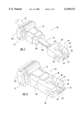
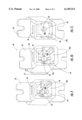
- FIG. 1 is an exploded perspective view of a gender selectable fiber optic connector of one embodiment of the present invention that includes a male configuration of the shroud.
- FIG. 2 is an exploded perspective view of the embodiment of the gender selectable fiber optic connector illustrated in FIG. 1 taken from another angle.
- FIG. 3 is a perspective view of the embodiment of the gender selectable fiber optic connector illustrated in FIGS. 1 and 2 following assembly of the connector.
- FIG. 4 is a perspective view of a male configuration of a shroud according to one embodiment of the present invention.
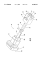
- FIG. 5 is an exploded perspective view of a gender selectable fiber optic connector having a male configuration of a shroud according to another embodiment of the present invention.
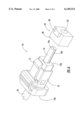
- FIG. 6 is an exploded perspective view of a gender selectable fiber optic connector of one embodiment of the present invention that includes a female configuration of the shroud.
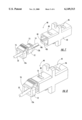
- FIG. 7 is an exploded perspective view of an outlet assembly including a connector according to one embodiment of the present invention.
- FIG. 8 is a perspective view of the embodiment of the outlet assembly illustrated in FIG. 7 following insertion of the housing and the ferrule into one end of the sleeve.
- FIG. 9 is a perspective view of an outlet housing according to one embodiment of the present invention prior to insertion of the ferrule that illustrates a pair of guide pins extending lengthwise through the aperture for aligning the ferrule and the outlet housing.
- FIG. 10 is a perspective view of the embodiment of the outlet assembly illustrated in FIG. 9 following insertion of a ferrule into the aperture defined by the outlet housing.
- FIG. 11 is a perspective view of an outlet housing according to another embodiment of the present invention prior to insertion of the ferrule which illustrates a pair of integral alignment ribs extending lengthwise through the aperture for aligning the ferrule and the outlet housing.
- the gender selectable fiber optic connector includes a housing 12 and a ferrule 14 operably connected to the housing.
- the housing is generally formed of a plastic material so as to define a lengthwise extending passageway 16 having a cross-sectional size which decreases from the rear end 12a of the housing toward the front end 12b of the housing, typically in a step-wise fashion.
- the housing also includes a latch 13, such as an RJ latch depicted in the illustrated embodiment, for mechanically engaging an alignment sleeve, outlet or other receptacle, as described in more detail hereinbelow.
- the ferrule 14 is typically formed of heavy glass filled thermoset materials, while, in multi-mode applications, the ferrule is typically formed of heavy glass filled thermoplastic materials.
- the gender selectable fiber optic connector 10 of the present invention can include a variety of ferrules
- the ferrule of one advantageous embodiment is a multi-fiber ferrule that has a substantially cylindrical shape, such as a DC or QC ferrule.
- the ferrule typically has an enlarged rear portion and an elongate, substantially cylindrical forward portion.
- the ferrule In order to assemble the ferrule and the housing 12, the ferrule is inserted through the rear end 12a of the housing such that the forward portion of the ferrule extends through an opening defined by the front end 12b of the housing and outwardly beyond the housing, while the enlarged rear portion of the ferrule is retained within the housing.
- the forward portion of the ferrule 14 also preferably defines at least one and, more typically, a pair of lengthwise extending grooves 14b opening outwardly through the exterior surface of the ferrule.
- the alignment grooves typically extend lengthwise along diametrically opposed sides of the ferrule.
- the ferrule can define alignment grooves that are positioned differently and can define different numbers of alignment groove if so desired.
- the gender selectable fiber optic connector 10 of the present invention also includes a shroud 18.
- the shroud has either a male configuration as shown in FIGS. 1-5 or a female configuration as shown in FIG. 6.
- the shroud includes a shroud body 20 that is typically formed of plastic and defines a lengthwise extending passageway 22.
- the shroud is adapted to be mounted upon the forward portion of the ferrule 14 such that the forward portion of the ferrule extends through the passageway defined by the shroud body. See FIG. 3.
- the shroud is also adapted to be operably connected, such as by mechanical engagement, to the housing 12. In the embodiment illustrated in FIG.
- the rear portion of the passageway defined by the shroud body is sized and shaped to snugly receive the front end 12b of the housing.
- the shroud body can be operably connected to the housing by means of frictional engagement of the front end of the housing within the rear portion of the passageway defined by the shroud body.
- the shroud and/or the housing can include various latch mechanisms for mechanically engaging the shroud body and the housing. Still further, other techniques, such as an adhesive or the like, can be employed to couple the shroud body and the housing.
- the rear portion of the passageway 22 defined by the housing preferably has a shape and size that corresponds to the shape and size of the front end of the housing.
- the forward portion of the passageway defined by the shroud 18 preferably has a shape and size that corresponds to the shape and size of the forward portion of the ferrule 14 which is inserted therethrough.
- the forward portion of the passageway defined by the shroud body is also generally cylindrical and is sized to snugly receive the forward portion of the ferrule.
- the ferrule could have other cross-sectional shapes (e.g., oval, rectangular, square, etc.) with a corresponding shroud body.
- the shroud 18 can be formed in either male or female configurations.
- the male configuration of the shroud also includes at least one guide pin 24 extending lengthwise through the passageway 22 defined by the shroud body 20 for engaging a respective alignment groove 14b defined by the ferrule 14 to therefore produce a male fiber optic connector 10. See FIG. 3.
- the shroud includes the same number of guide pins as alignment grooves defined by the ferrule. Since the ferrule defines a pair of diametrically opposed alignment grooves, the shroud also generally includes a pair of guide pins extending lengthwise along diametrically opposed portions of the passageway defined by the shroud body.
- the guide pins 24 are partially embedded within the shroud body 20 so as to extend lengthwise through the passageway 22 and outwardly beyond at least one end of the shroud body, that is, beyond the forward end of the shroud body. While the guide pins generally extend beyond the forward end of the shroud body, the guide pins preferably do not extend beyond the rear end of the shroud body so as not to interfere with the mounting of the shroud body upon the front end 12b of the housing 12.
- the guide pins can be embedded to different depths within the shroud body, the guide pins of one embodiment are embedded to a depth that is approximately equal to the radius of the guide pins, such that about one-half of each guide pin is embedded within the shroud body and about one-half of each guide pin extends into the passageway defined by the shroud body.
- the portion of each guide pin which extends into the passageway defined by the shroud body is approximately equal in size and shape of the respective alignment groove 14b defined by the ferrule 14 such that the guide pins will be snugly received within the respective alignment grooves.
- the shroud body of one embodiment is injection molded.
- the mold can be designed to receive and hold the guide pins such that the shroud body can be injection molded around the guide pins.
- the mold can define a pair of grooves extending lengthwise through the forward portion of the passageway 22 defined by the shroud body. After removing the shroud body from the mold of this alternate embodiment, the guide pins can be inserted into respective grooves and secured by means of an adhesive or the like.
- the shroud body 20 and guide pins 24 can be a monolithic piece, the guide pins having been injection molded with the remainder of the shroud body 20.
- the male configuration of the shroud 18 illustrated in FIGS. 1-4 and described above can be reliably mounted upon the front end 12b of the housing 12 in order to create a male connector 10
- the male configuration of the shroud can be constructed in a variety of other manners without departing from the spirit and scope of the present invention.
- the male configuration of the shroud can include multiple components that are assembled upon the forward portion of the ferrule 14 in order to appropriately configure the connector.
- the shroud body 20 in addition to defining a lengthwise extending passageway, can define at least one and, more commonly, a pair of alignment grooves 21 that extend lengthwise through the shroud body and which open into the passageway defined thereby.
- the shroud of this embodiment also includes a pin carrier 25 adapted to be mounted upon said ferrule proximate the shroud body.
- the pin carrier can be embodied as a carrier ring that is preferably sized so as to snugly encircle the ferrule.
- the shroud further includes at least one and, more commonly, a pair of guide pins 24 connected to the pin carrier and extending through the passageway defined by the shroud body. More particularly, the guide pins generally extend outwardly from the pin carrier so as to extend through the guide pin openings defined by the respective alignment grooves of the shroud body and the ferrule.
- the guide pins 24 Upon mounting either embodiment of the male configuration of the shroud 18 upon the forward portion of the ferrule 14, the guide pins 24 will engage respective alignment grooves 14b defined by the ferrule in order to align the shroud and the ferrule.
- the shroud body 20 will engage the front end 12b of the housing 12 in order to mechanically couple the shroud and the housing.
- a male fiber optic connector 10 can be produced in which the forward end of the ferrule and the guide pins extend beyond the shroud body.
- the ferrule and the passageway 22 defined by the shroud body are substantially cylindrical so as to have a substantially circular shape in lateral cross-section.
- the shroud of these embodiments of the present invention can be used on a first type of fiber optic connector, such as a DC ferrule secured in a rectangularly shaped housing rather than a square housing of the SC-DC connector, that is to be mated with a second type of fiber optic connector, such as an MT connector, thereby increasing the flexibility and accuracy with which different types of connectors and/or ferrules can be mated.
- a first type of fiber optic connector such as a DC ferrule secured in a rectangularly shaped housing rather than a square housing of the SC-DC connector
- a second type of fiber optic connector such as an MT connector
- the shroud 18 can also include various alignment features for aligning the resulting fiber optic connector 10 with another fiber optic connector or with an alignment sleeve, an outlet or other receptacle.
- the shroud body 20 can include an outwardly extending alignment key 28 and the forward end of the shroud body can define several cut-outs 30 that are sized and shaped to mate with corresponding features within an alignment sleeve, an outlet or other receptacle.
- the alignment key and cut-out portions of the shroud bodies illustrated in FIGS. 1-5 are adapted to engage corresponding alignment features within a conventional sleeve, outlet or receptacle that has been designed to receive MT connectors.
- the shroud can include other alignment features, if so desired, without departing from the spirit and scope of the present invention.
- the gender selectable fiber optic connector 10 of the present invention also includes a female configuration of the shroud 18 which, unlike the male configuration of the shroud, does not include guide pins 24.
- the female configuration of the shroud does include a shroud body 20 having the same general size and external shape as the shroud body of the male configuration.
- the shroud body of the female configuration defines a lengthwise extending passageway 22 having a rear portion that is sized and shaped to be mounted upon the front end 12b of the housing 12 and a forward portion through which the forward portion of the ferrule 14 extends.
- the forward portion of the passageway defined by the female configuration of the shroud can be a smooth-walled, cylindrical passageway since the shroud does not include guide pins.
- the passageway 22 defined by the female configuration of the shroud body 18 can include one or more lengthwise extending grooves opening into the passageway at locations corresponding to the relative locations of the alignment grooves 14b defined by the ferrule 14.
- the grooves defined by the ferrule and the shroud body can cooperate to define substantially cylindrical holes once the ferrule is inserted through the passageway defined by the shroud body.
- the resulting female fiber optic connector can therefore be aligned with a male fiber optic connector by inserting the guide pins of the male fiber optic connector into respective ones of the holes defined by the female fiber optic connector of this embodiment.
- the passageway defined by the forward portion of the shroud body can include lengthwise extending alignment ribs that extend into the passageway at locations corresponding to the relative locations of the alignment grooves defined by the ferrule.
- the alignment ribs can engage corresponding alignment grooves defined by the ferrule as the ferrule is inserted into the passageway defined by the shroud body, thereby aligning the shroud body and the ferrule.
- the female configuration of the shroud body 20 can also include various alignment features.
- the female configuration of the shroud body can include an alignment key 28 and can define cut-out portions 30 in order to align the resulting female fiber optic connector within an alignment sleeve, outlet or other receptacle.
- the multi-fiber ferrule 14 is initially mounted at least partially within the housing 12.
- the ferrule is mounted at least partially within the housing such that the enlarged rear portion of the ferrule is disposed within the housing while the forward portion of the ferrule extends through an opening defined by the front end 12b of the housing and outwardly beyond the housing.
- the ferrule is mounted upon a plurality of optical fibers 32 such that the end portions of the optical fibers are exposed through the forward end 14a of the ferrule.
- the forward end 14a of the ferrule 14 and the exposed end portions of the optical fibers 32 are thereafter polished.
- the polishing can be conducted after assembling the ferrule and the housing 12 for at least two reasons. First the polishing datum or point of reference during polishing operations is generally accessible even after the ferrule and the housing have been assembled since the cylindrical exterior surface of the forward portion of the ferrule which serves as the polishing datum extends beyond the housing and is exposed following the assembly process.
- the forward end of the ferrule and the exposed end portions of the optical fibers can be polished following assembly of the ferrule and the housing since the fiber optic connector does not yet include guide pins 24 which would generally extend beyond the forward end of the ferrule so as to obstruct polishing operations.
- a shroud 18 having either a male configuration or a female configuration is selected and is thereafter mounted upon the ferrule. Since the shroud is not mounted upon the ferrule until after the assembly and polishing operations are complete, the shroud can be selectively mounted upon the ferrule during field installation of the fiber optic connector 10. As such, both male and female fiber optic connectors need not be assembled in the factory and maintained in inventory. Instead, the ferrule and the housing 12 can be assembled and, in some instances, the ferrule and the end portions of the optical fibers can be polished during factory assembly. A technician can therefore maintain an inventory of the generic ferrule and housing subassemblies as well as male and female configurations of the shroud that can be mounted upon the ferrule in the field once the technician has determined the particular installation requirements.
- an outlet assembly 40 is also provided according to one aspect of the present invention in order to align a substantially cylindrical ferrule 14, such as a DC or QC ferrule, with a fiber optic connector having a rectangular shape in lateral cross-section, such as an MT connector or the gender selectable fiber optic connector 10 having a rectangularly-shaped shroud.
- a substantially cylindrical ferrule 14 such as a DC or QC ferrule
- a fiber optic connector having a rectangular shape in lateral cross-section such as an MT connector or the gender selectable fiber optic connector 10 having a rectangularly-shaped shroud.
- an outlet assembly is intended to include not only wall outlets, but also other receptacles or alignment sleeves that are adapted to receive a fiber optic connector having a rectangular shape in lateral cross-section.
- the outlet assembly 40 includes an outlet housing 42 extending between opposed first and second ends and having a first portion 42a defining a lengthwise extending passageway adjacent the first end of the outlet housing. Since the outlet assembly is generally designed to receive a fiber optic connector having a generally rectangular shape in lateral cross-section, the passageway defined by the first portion of the outlet housing is preferably adapted to receive a fiber optic connector having a generally rectangular shape in lateral cross-section, such as an MT connector or the gender selectable fiber optic connector 10 having a rectangularly-shaped shroud.
- the first portion of the outlet housing preferably includes L-shaped corner portions 44 for engaging corresponding corner portions of the fiber optic connector in order to appropriately receive and guide the fiber optic connector into the outlet.
- the first portion of the outlet housing also generally includes one or more windows 46 for engaging corresponding latch members of the fiber optic connector in order to mechanically couple the fiber optic connector and the outlet housing.
- the outlet assembly can include other mechanisms for mechanically coupling the outlet housing and the fiber optic connector, if so desired.
- the outlet housing 42 also includes a second portion 42b that defines a substantially circular aperture opening into the passageway defined by the first portion 42a of the outlet housing.
- the outlet assembly 40 of this aspect of the present invention also includes a substantially cylindrical ferrule 14, such as a DC or QC ferrule, that extends into the aperture defined by the second portion of the outlet housing such that a forward end 14a of the ferrule is exposed within the passageway defined by the first portion of the outlet housing.
- the ferrule can be operably connected to a housing 12 such that the forward portion of the ferrule extends outwardly beyond the housing.
- the outlet housing of one advantageous embodiment further includes a third portion 42c adjacent the second end of the outlet housing which also defines a lengthwise extending passageway for receiving the ferrule and the housing.
- the housing can be inserted into the passageway defined by the third portion of the outlet housing such that the forward portion of the ferrule that extends beyond the housing is inserted into the substantially circular aperture defined by the second portion of the outlet housing.
- the third portion of the outlet housing preferably defines a passageway having a shape and size corresponding to the shape and size of the housing to be inserted therein.
- the third portion of the outlet housing preferably defines a window 48 for engaging the housing latch 13 as the housing is inserted into the passageway.
- the outlet can include other mechanisms, including frictional or adhesive engagement, for mechanically engaging the ferrule and/or the housing.
- the forward end 14a of the ferrule 14 preferably extends through the substantially circular aperture defined by the second portion 42b of the outlet housing and into the passageway defined by the first portion 42a of the outlet housing. While the ferrule can protrude into the passageway defined by the first portion of the outlet housing by different amounts, the ferrule typically protrudes into the passageway defined by the first portion of the outlet housing by about 0.25 to about 0.5 mm.
- the ferrule 14 typically defines at least one and, more commonly, a pair of lengthwise extending alignment grooves 14b.
- the outlet assembly 40 of this aspect of the present invention also preferably includes at least one alignment member 50 extending lengthwise through the aperture for engaging the respective alignment groove defined by the ferrule such that the ferrule and the outlet housing 42 are thereby aligned.
- the outlet assembly includes the same number of alignment members as the number of alignment grooves defined by the ferrule. Since the ferrule typically defines a pair of diametrically opposed alignment grooves, the outlet also typically includes a pair of alignment members positioned in a diametrically opposed relationship and extending lengthwise through the aperture. See FIGS. 9-11.
- the alignment members 50 can include guide pins that are at least partially embedded within the outlet housing 42 and, more particularly, within the second portion 42b of the outlet housing.
- the guide pins can be embedded within the outlet housing in a variety of manners.
- the guide pins can be secured, such as by adhesive or the like, in respective grooves which are formed during the molding of the outlet housing so as to extend lengthwise through the aperture.
- the guide pins can be secured within the mold and the outlet housing can be injection molded around the guide pins.
- guide pins can be embedded at different depths within the outlet housing as also described above in conjunction with the male configuration of the shroud, the guide pins are commonly embedded in the second portion of the outlet housing such that about half of each guide pin is embedded within the outlet housing and about half each guide pin protrudes into the substantially circular aperture. See FIGS. 9 and 10.
- the alignment members 50 need not be guide pins. Instead, the alignment members can be alignment ribs that are formed integrally with the outlet housing 42, such as during an injection molding process. As described above in conjunction with the guide pins, the alignment ribs extend lengthwise through the aperture, in order to engage the corresponding alignment grooves 14b defined by the ferrule 14 in order to align the ferrule and the outlet housing.
- guide pins are utilized as the alignment members in single mode applications, while alignment ribs are utilized as the alignment members in multi-mode applications.
- the outlet assembly 40 of this aspect of the present invention can be mounted, such as within a wall or within the housing of an optical device such as a transceiver, such that the passageway defined by the first portion 42a of the outlet housing 42 opens outwardly in order to receive a fiber optic connector.
- the ferrule 14 Prior to insertion of the fiber optic connector, the ferrule 14 has therefore generally already been mounted within the outlet housing such that the forward 14a of the ferrule extends through the substantially circular aperture and protrudes in the passageway defined by the first portion of the outlet housing.
- a fiber optic connector having a rectangular shape in lateral cross-section such as an MT connector or the gender selectable fiber optic connector 10 having a rectangularly-shaped shroud, can then be inserted into the passageway defined by the first portion of the outlet housing which brings the fiber optic connector into an aligned relationship with the substantially cylindrical ferrule mounted within the outlet.
- the outlet assembly 40 of this aspect of the present invention further improves the alignment accuracy of the optical fibers upon which the respective ferrules are mounted.
- the alignment of the outlet housing 42 and the ferrule is primarily based upon the engagement of the alignment members 50 and the exterior surface of the substantially cylindrical ferrule.
- the alignment of the outlet housing and the substantially cylindrical ferrule is based upon the engagement of the alignment members of the outlet with the alignment grooves 14b defied by the exterior surface of the ferrule.
- the exterior surface of the substantially cylindrical ferrule typically serves as the polishing datum and is therefore precisely defined with respect to the positions of the optical fibers at the forward end 14a of the ferrule.
- the outlet assembly of this aspect of the present invention should provide improved alignment accuracy between the optical fibers terminated by the substantially cylindrical ferrule and the rectangularly-shaped fiber optic connector that is inserted into the passageway defined by the first portion 42a of the outlet housing. This improved alignment accuracy is particularly important in those applications in which the ferrules are mounted upon multiple single mode fibers which must be positioned and aligned in an extremely precise manner.
Abstract
Description
Claims (16)
Priority Applications (3)
| Application Number | Priority Date | Filing Date | Title |
|---|---|---|---|
| US09/223,908 US6149313A (en) | 1998-12-31 | 1998-12-31 | Gender selectable fiber optic connector and associated fabrication method |
| CA002288249A CA2288249A1 (en) | 1998-12-31 | 1999-11-02 | Gender selectable fiber optic connector and associated fabrication method |
| EP99310242A EP1016885A1 (en) | 1998-12-31 | 1999-12-20 | Gender selectable fiber optic connector |
Applications Claiming Priority (1)
| Application Number | Priority Date | Filing Date | Title |
|---|---|---|---|
| US09/223,908 US6149313A (en) | 1998-12-31 | 1998-12-31 | Gender selectable fiber optic connector and associated fabrication method |
Publications (1)
| Publication Number | Publication Date |
|---|---|
| US6149313A true US6149313A (en) | 2000-11-21 |
Family
ID=22838479
Family Applications (1)
| Application Number | Title | Priority Date | Filing Date |
|---|---|---|---|
| US09/223,908 Expired - Fee Related US6149313A (en) | 1998-12-31 | 1998-12-31 | Gender selectable fiber optic connector and associated fabrication method |
Country Status (3)
| Country | Link |
|---|---|
| US (1) | US6149313A (en) |
| EP (1) | EP1016885A1 (en) |
| CA (1) | CA2288249A1 (en) |
Cited By (95)
| Publication number | Priority date | Publication date | Assignee | Title |
|---|---|---|---|---|
| US6364685B1 (en) * | 2000-11-03 | 2002-04-02 | Randy Marshall Manning | Connector with articulated latch |
| US6412988B1 (en) * | 1999-12-30 | 2002-07-02 | Corning Cable Systems Llc | Ferrule and fiber optic connector housing having enlarged shoulders |
| US6419400B1 (en) * | 2000-04-07 | 2002-07-16 | Panduit Corp. | Fiber optic sleeve with drafted corner-wall sections |
| US6439776B1 (en) * | 2000-05-15 | 2002-08-27 | Joseph C. Harrison | Fiber optic loop support |
| US20020126960A1 (en) * | 2000-07-17 | 2002-09-12 | Michael Gurreri | Connector and receptacle containing a physical security feature |
| US20020168149A1 (en) * | 2001-05-08 | 2002-11-14 | Autonetworks Technologies, Ltd. | Optical junction connector device and optical junction connector |
| US6623172B1 (en) * | 1999-05-12 | 2003-09-23 | Corning Cable Systems Llc | Removably mounted fiber optic connector and associated adapter |
| US6648520B2 (en) * | 2001-09-28 | 2003-11-18 | Corning Cable Systems Llc | Fiber optic plug |
| US6688782B1 (en) * | 1999-08-23 | 2004-02-10 | Corning Cable Systems Llc | Universal ferrule |
| US6711440B2 (en) | 2002-04-11 | 2004-03-23 | Biophan Technologies, Inc. | MRI-compatible medical device with passive generation of optical sensing signals |
| US6718207B2 (en) | 2001-02-20 | 2004-04-06 | Biophan Technologies, Inc. | Electromagnetic interference immune tissue invasive system |
| US6725092B2 (en) | 2002-04-25 | 2004-04-20 | Biophan Technologies, Inc. | Electromagnetic radiation immune medical assist device adapter |
| US6731979B2 (en) | 2001-08-30 | 2004-05-04 | Biophan Technologies Inc. | Pulse width cardiac pacing apparatus |
| US20040105239A1 (en) * | 2002-11-29 | 2004-06-03 | Chiang Tu Kuo | Optical transceiver connection module |
| US6814499B2 (en) | 2002-11-13 | 2004-11-09 | Itt Manufacturing Enterprises, Inc. | Optical fiber connector latching mechanism |
| US6829509B1 (en) | 2001-02-20 | 2004-12-07 | Biophan Technologies, Inc. | Electromagnetic interference immune tissue invasive system |
| US6830382B1 (en) * | 2001-12-20 | 2004-12-14 | National Semiconductor Corporation | Miniature form-factor connecter for fiber optic modules |
| US20070093114A1 (en) * | 2005-10-26 | 2007-04-26 | Yi-Yu Chang | Resilient latching device |
| US20070300278A1 (en) * | 2006-06-27 | 2007-12-27 | Carey John L | Plug and play fiber distribution hub |
| US20080044137A1 (en) * | 2006-08-15 | 2008-02-21 | Luther James P | Ruggedized fiber optic connector assembly |
| US20080131055A1 (en) * | 2006-12-04 | 2008-06-05 | Parkman L Edward | Keyed push-pull type fiber optic connection system |
| US20080226234A1 (en) * | 2007-03-13 | 2008-09-18 | Scott Droege | Fiber Optic Connector with Protective Cap |
| US7540667B2 (en) | 2007-08-01 | 2009-06-02 | Ortronics, Inc. | Positional differentiating connector assembly |
| US7572065B2 (en) | 2007-01-24 | 2009-08-11 | Adc Telecommunications, Inc. | Hardened fiber optic connector |
| US7591595B2 (en) | 2007-01-24 | 2009-09-22 | Adc Telelcommunications, Inc. | Hardened fiber optic adapter |
| US7614797B2 (en) | 2007-01-24 | 2009-11-10 | Adc Telecommunications, Inc. | Fiber optic connector mechanical interface converter |
| US20090310928A1 (en) * | 2008-06-12 | 2009-12-17 | Wolf Kluwe | Universal cable bracket |
| US7677814B2 (en) | 2007-05-06 | 2010-03-16 | Adc Telecommunications, Inc. | Mechanical interface converter for making non-ruggedized fiber optic connectors compatible with a ruggedized fiber optic adapter |
| US7686519B2 (en) | 2007-06-18 | 2010-03-30 | Adc Telecommunications, Inc. | Hardened fiber optic housing and cable assembly |
| US20100080516A1 (en) * | 2008-09-30 | 2010-04-01 | Coleman Casey A | Retention Bodies for Fiber Optic Cable Assemblies |
| US20100080525A1 (en) * | 2008-09-30 | 2010-04-01 | Coleman Casey A | Retention Bodies for Fiber Optic Cable Assemblies |
| US7722258B2 (en) | 2007-05-06 | 2010-05-25 | Adc Telecommunications, Inc. | Interface converter for SC fiber optic connectors |
| US20100158447A1 (en) * | 2008-12-19 | 2010-06-24 | The Furukawa Electric Co., Ltd. | Optical connector |
| US7744286B2 (en) | 2007-12-11 | 2010-06-29 | Adc Telecommunications, Inc. | Hardened fiber optic connection system with multiple configurations |
| USRE42522E1 (en) | 2003-09-08 | 2011-07-05 | Adc Telecommunications, Inc. | Ruggedized fiber optic connection |
| US8285096B2 (en) | 2008-09-30 | 2012-10-09 | Corning Cable Systems Llc | Fiber optic cable assemblies and securing methods |
| US8348686B1 (en) * | 2011-10-11 | 2013-01-08 | Li-Ping Huang | Plug security structure for electrical connector |
| US8433171B2 (en) | 2009-06-19 | 2013-04-30 | Corning Cable Systems Llc | High fiber optic cable packing density apparatus |
| US8527046B2 (en) | 2000-04-20 | 2013-09-03 | Medtronic, Inc. | MRI-compatible implantable device |
| US8538226B2 (en) | 2009-05-21 | 2013-09-17 | Corning Cable Systems Llc | Fiber optic equipment guides and rails configured with stopping position(s), and related equipment and methods |
| US8542973B2 (en) | 2010-04-23 | 2013-09-24 | Ccs Technology, Inc. | Fiber optic distribution device |
| US8593828B2 (en) | 2010-02-04 | 2013-11-26 | Corning Cable Systems Llc | Communications equipment housings, assemblies, and related alignment features and methods |
| US8625950B2 (en) | 2009-12-18 | 2014-01-07 | Corning Cable Systems Llc | Rotary locking apparatus for fiber optic equipment trays and related methods |
| US8636424B2 (en) | 2010-10-22 | 2014-01-28 | Panduit Corp. | Optical communication connector |
| US8660397B2 (en) | 2010-04-30 | 2014-02-25 | Corning Cable Systems Llc | Multi-layer module |
| US8662760B2 (en) | 2010-10-29 | 2014-03-04 | Corning Cable Systems Llc | Fiber optic connector employing optical fiber guide member |
| US8699838B2 (en) | 2009-05-14 | 2014-04-15 | Ccs Technology, Inc. | Fiber optic furcation module |
| US8705926B2 (en) | 2010-04-30 | 2014-04-22 | Corning Optical Communications LLC | Fiber optic housings having a removable top, and related components and methods |
| US8712206B2 (en) | 2009-06-19 | 2014-04-29 | Corning Cable Systems Llc | High-density fiber optic modules and module housings and related equipment |
| US8708573B2 (en) | 2000-07-17 | 2014-04-29 | Tyco Electronics Corporation | Connector system with physical security feature |
| US8718436B2 (en) | 2010-08-30 | 2014-05-06 | Corning Cable Systems Llc | Methods, apparatuses for providing secure fiber optic connections |
| US8807843B2 (en) | 2000-07-17 | 2014-08-19 | Tyco Electronics Corporation | Connector system with physical security feature |
| US20140314377A1 (en) * | 2013-04-17 | 2014-10-23 | Hon Hai Precision Industry Co., Ltd. | Optical connector having high coupling precision |
| US8879881B2 (en) | 2010-04-30 | 2014-11-04 | Corning Cable Systems Llc | Rotatable routing guide and assembly |
| US8913866B2 (en) | 2010-03-26 | 2014-12-16 | Corning Cable Systems Llc | Movable adapter panel |
| US8953924B2 (en) | 2011-09-02 | 2015-02-10 | Corning Cable Systems Llc | Removable strain relief brackets for securing fiber optic cables and/or optical fibers to fiber optic equipment, and related assemblies and methods |
| US8985862B2 (en) | 2013-02-28 | 2015-03-24 | Corning Cable Systems Llc | High-density multi-fiber adapter housings |
| US8989547B2 (en) | 2011-06-30 | 2015-03-24 | Corning Cable Systems Llc | Fiber optic equipment assemblies employing non-U-width-sized housings and related methods |
| US8995812B2 (en) | 2012-10-26 | 2015-03-31 | Ccs Technology, Inc. | Fiber optic management unit and fiber optic distribution device |
| US9008485B2 (en) | 2011-05-09 | 2015-04-14 | Corning Cable Systems Llc | Attachment mechanisms employed to attach a rear housing section to a fiber optic housing, and related assemblies and methods |
| US9020320B2 (en) | 2008-08-29 | 2015-04-28 | Corning Cable Systems Llc | High density and bandwidth fiber optic apparatuses and related equipment and methods |
| US9022814B2 (en) | 2010-04-16 | 2015-05-05 | Ccs Technology, Inc. | Sealing and strain relief device for data cables |
| US9038832B2 (en) | 2011-11-30 | 2015-05-26 | Corning Cable Systems Llc | Adapter panel support assembly |
| US9042702B2 (en) | 2012-09-18 | 2015-05-26 | Corning Cable Systems Llc | Platforms and systems for fiber optic cable attachment |
| US9059578B2 (en) | 2009-02-24 | 2015-06-16 | Ccs Technology, Inc. | Holding device for a cable or an assembly for use with a cable |
| US9075216B2 (en) | 2009-05-21 | 2015-07-07 | Corning Cable Systems Llc | Fiber optic housings configured to accommodate fiber optic modules/cassettes and fiber optic panels, and related components and methods |
| US9075217B2 (en) | 2010-04-30 | 2015-07-07 | Corning Cable Systems Llc | Apparatuses and related components and methods for expanding capacity of fiber optic housings |
| US9116324B2 (en) | 2010-10-29 | 2015-08-25 | Corning Cable Systems Llc | Stacked fiber optic modules and fiber optic equipment configured to support stacked fiber optic modules |
| US9213161B2 (en) | 2010-11-05 | 2015-12-15 | Corning Cable Systems Llc | Fiber body holder and strain relief device |
| US9250409B2 (en) | 2012-07-02 | 2016-02-02 | Corning Cable Systems Llc | Fiber-optic-module trays and drawers for fiber-optic equipment |
| US9279951B2 (en) | 2010-10-27 | 2016-03-08 | Corning Cable Systems Llc | Fiber optic module for limited space applications having a partially sealed module sub-assembly |
| US9310569B2 (en) * | 2014-02-21 | 2016-04-12 | Alliance Fiber Optic Products, Inc. | Reconfigurable fiber optic adapter |
| US9519118B2 (en) | 2010-04-30 | 2016-12-13 | Corning Optical Communications LLC | Removable fiber management sections for fiber optic housings, and related components and methods |
| US9632270B2 (en) | 2010-04-30 | 2017-04-25 | Corning Optical Communications LLC | Fiber optic housings configured for tool-less assembly, and related components and methods |
| US9645317B2 (en) | 2011-02-02 | 2017-05-09 | Corning Optical Communications LLC | Optical backplane extension modules, and related assemblies suitable for establishing optical connections to information processing modules disposed in equipment racks |
| US9720195B2 (en) | 2010-04-30 | 2017-08-01 | Corning Optical Communications LLC | Apparatuses and related components and methods for attachment and release of fiber optic housings to and from an equipment rack |
| US10094996B2 (en) | 2008-08-29 | 2018-10-09 | Corning Optical Communications, Llc | Independently translatable modules and fiber optic equipment trays in fiber optic equipment |
| US10114176B2 (en) | 2000-05-26 | 2018-10-30 | Corning Optical Communications LLC | Fiber optic drop cables and preconnectorized assemblies |
| US10359577B2 (en) | 2017-06-28 | 2019-07-23 | Corning Research & Development Corporation | Multiports and optical connectors with rotationally discrete locking and keying features |
| US10379298B2 (en) | 2017-06-28 | 2019-08-13 | Corning Research & Development Corporation | Fiber optic connectors and multiport assemblies including retention features |
| US10444443B2 (en) | 2013-06-27 | 2019-10-15 | CommScope Connectivity Belgium BVBA | Fiber optic cable anchoring device for use with fiber optic connectors and methods of using the same |
| US10564367B1 (en) * | 2018-10-18 | 2020-02-18 | Benchmark Electronics, Inc. | MT connector assembly and method therefor |
| US10768377B2 (en) | 2016-11-02 | 2020-09-08 | Us Conec, Ltd. | Fiber optic guide pin changer and field tool with adapter |
| CN111971601A (en) * | 2018-04-06 | 2020-11-20 | 美国康涅克有限公司 | Flexible push-pull boot sleeve and press-fit body for optical fiber connector |
| CN112352175A (en) * | 2018-05-15 | 2021-02-09 | 扇港元器件股份有限公司 | Optical fiber connector |
| US11187859B2 (en) | 2017-06-28 | 2021-11-30 | Corning Research & Development Corporation | Fiber optic connectors and methods of making the same |
| US11294133B2 (en) | 2019-07-31 | 2022-04-05 | Corning Research & Development Corporation | Fiber optic networks using multiports and cable assemblies with cable-to-connector orientation |
| US11294135B2 (en) | 2008-08-29 | 2022-04-05 | Corning Optical Communications LLC | High density and bandwidth fiber optic apparatuses and related equipment and methods |
| US11422312B2 (en) * | 2019-05-09 | 2022-08-23 | Commscope Technologies Llc | Fiber optic converter |
| US11493701B2 (en) | 2010-10-22 | 2022-11-08 | Panduit Corp. | Optical communications connectors |
| US11536921B2 (en) | 2020-02-11 | 2022-12-27 | Corning Research & Development Corporation | Fiber optic terminals having one or more loopback assemblies |
| US11604320B2 (en) | 2020-09-30 | 2023-03-14 | Corning Research & Development Corporation | Connector assemblies for telecommunication enclosures |
| US11686913B2 (en) | 2020-11-30 | 2023-06-27 | Corning Research & Development Corporation | Fiber optic cable assemblies and connector assemblies having a crimp ring and crimp body and methods of fabricating the same |
| US11880076B2 (en) | 2020-11-30 | 2024-01-23 | Corning Research & Development Corporation | Fiber optic adapter assemblies including a conversion housing and a release housing |
| US11927810B2 (en) | 2020-11-30 | 2024-03-12 | Corning Research & Development Corporation | Fiber optic adapter assemblies including a conversion housing and a release member |
Families Citing this family (7)
| Publication number | Priority date | Publication date | Assignee | Title |
|---|---|---|---|---|
| US20100106146A1 (en) * | 2008-10-24 | 2010-04-29 | Boitor Mihai I A | Hand-held portable laser surgical device |
| US8224185B2 (en) * | 2008-12-11 | 2012-07-17 | Kaist | USB compatible apparatus for connecting between optical USB device and electrical USB device |
| EP2207053B1 (en) * | 2009-01-07 | 2013-03-20 | The Furukawa Electric Co., Ltd. | Multiple optical fiber connector |
| US8500339B2 (en) * | 2011-01-11 | 2013-08-06 | Avago Technologies General Ip (Singapore) Pte. Ltd. | Locking device and method for use with a multi-fiber push on (MPO) connector module to prevent the MPO connector module from being decoupled from a receptacle |
| US9417406B2 (en) | 2012-08-31 | 2016-08-16 | Corning Cable Systems Llc | Cable assemblies and optical connector assemblies employing a unitary alignment pin and translating element |
| US10139573B2 (en) | 2012-08-31 | 2018-11-27 | Corning Optical Communications LLC | Cable assemblies, optical connector assemblies, and optical connector subassemblies employing a unitary alignment pin and cover |
| CN208140982U (en) * | 2014-10-03 | 2018-11-23 | 康宁光电通信有限责任公司 | Hood assembly, optical fiber connector and fiber optical cable assembly for optical fiber connector |
Citations (9)
| Publication number | Priority date | Publication date | Assignee | Title |
|---|---|---|---|---|
| EP0105589A1 (en) * | 1982-09-07 | 1984-04-18 | AMP INCORPORATED (a New Jersey corporation) | Gender change connector |
| US4907852A (en) * | 1988-02-05 | 1990-03-13 | Tokai Rubber Industries, Ltd. | Optical fiber connector and method for producing the same |
| US5093881A (en) * | 1989-10-17 | 1992-03-03 | Societa' Cavi Pirelli S.P.A. | Connector for interconnecting optical fiber cable ribbons |
| US5214730A (en) * | 1991-05-13 | 1993-05-25 | Nippon Telegraph And Telephone Corporation | Multifiber optical connector plug with low reflection and low insertion loss |
| US5519799A (en) * | 1994-03-08 | 1996-05-21 | Hitachi Cable, Ltd. | Optical fiber array structure |
| EP0819960A2 (en) * | 1996-07-15 | 1998-01-21 | Seiko Instruments Inc. | Universal optical fiber connectors and basic plugs thereof |
| US5727102A (en) * | 1995-11-09 | 1998-03-10 | Electronics And Telecommunications Research Institute | Multifiber optical connector for optical ribbon cable |
| US5727101A (en) * | 1995-10-06 | 1998-03-10 | Siecor Corporation | Monolithic ferrule for receiving and positioning multiple optical fibers and an optical fiber connector incorporating same |
| US5940561A (en) * | 1997-04-23 | 1999-08-17 | Siecor Corporation | Adapter assembly for precise alignment of fiber optic connectors |
-
1998
- 1998-12-31 US US09/223,908 patent/US6149313A/en not_active Expired - Fee Related
-
1999
- 1999-11-02 CA CA002288249A patent/CA2288249A1/en not_active Abandoned
- 1999-12-20 EP EP99310242A patent/EP1016885A1/en not_active Withdrawn
Patent Citations (9)
| Publication number | Priority date | Publication date | Assignee | Title |
|---|---|---|---|---|
| EP0105589A1 (en) * | 1982-09-07 | 1984-04-18 | AMP INCORPORATED (a New Jersey corporation) | Gender change connector |
| US4907852A (en) * | 1988-02-05 | 1990-03-13 | Tokai Rubber Industries, Ltd. | Optical fiber connector and method for producing the same |
| US5093881A (en) * | 1989-10-17 | 1992-03-03 | Societa' Cavi Pirelli S.P.A. | Connector for interconnecting optical fiber cable ribbons |
| US5214730A (en) * | 1991-05-13 | 1993-05-25 | Nippon Telegraph And Telephone Corporation | Multifiber optical connector plug with low reflection and low insertion loss |
| US5519799A (en) * | 1994-03-08 | 1996-05-21 | Hitachi Cable, Ltd. | Optical fiber array structure |
| US5727101A (en) * | 1995-10-06 | 1998-03-10 | Siecor Corporation | Monolithic ferrule for receiving and positioning multiple optical fibers and an optical fiber connector incorporating same |
| US5727102A (en) * | 1995-11-09 | 1998-03-10 | Electronics And Telecommunications Research Institute | Multifiber optical connector for optical ribbon cable |
| EP0819960A2 (en) * | 1996-07-15 | 1998-01-21 | Seiko Instruments Inc. | Universal optical fiber connectors and basic plugs thereof |
| US5940561A (en) * | 1997-04-23 | 1999-08-17 | Siecor Corporation | Adapter assembly for precise alignment of fiber optic connectors |
Cited By (199)
| Publication number | Priority date | Publication date | Assignee | Title |
|---|---|---|---|---|
| US6623172B1 (en) * | 1999-05-12 | 2003-09-23 | Corning Cable Systems Llc | Removably mounted fiber optic connector and associated adapter |
| US6688782B1 (en) * | 1999-08-23 | 2004-02-10 | Corning Cable Systems Llc | Universal ferrule |
| US6412988B1 (en) * | 1999-12-30 | 2002-07-02 | Corning Cable Systems Llc | Ferrule and fiber optic connector housing having enlarged shoulders |
| US6485195B2 (en) | 1999-12-30 | 2002-11-26 | Corning Cable Systems Llc | Ferrule and fiber optic connector housing having enlarged shoulders |
| US6419400B1 (en) * | 2000-04-07 | 2002-07-16 | Panduit Corp. | Fiber optic sleeve with drafted corner-wall sections |
| US8527046B2 (en) | 2000-04-20 | 2013-09-03 | Medtronic, Inc. | MRI-compatible implantable device |
| US6439776B1 (en) * | 2000-05-15 | 2002-08-27 | Joseph C. Harrison | Fiber optic loop support |
| US10114176B2 (en) | 2000-05-26 | 2018-10-30 | Corning Optical Communications LLC | Fiber optic drop cables and preconnectorized assemblies |
| US8794849B2 (en) | 2000-07-17 | 2014-08-05 | Tyco Electronics Corporation | Connector system with physical security features |
| US8708573B2 (en) | 2000-07-17 | 2014-04-29 | Tyco Electronics Corporation | Connector system with physical security feature |
| US6960025B2 (en) * | 2000-07-17 | 2005-11-01 | Tyco Electronics Corporation | Connector and receptacle containing a physical security feature |
| US8807843B2 (en) | 2000-07-17 | 2014-08-19 | Tyco Electronics Corporation | Connector system with physical security feature |
| US8905647B2 (en) | 2000-07-17 | 2014-12-09 | Tyco Electronics Corporation | Connector system with physical security feature |
| US8961031B2 (en) | 2000-07-17 | 2015-02-24 | Tyco Electronics Corporation | Connector system with physical security feature |
| US20150131944A1 (en) * | 2000-07-17 | 2015-05-14 | Tyco Electronics Corporation | Connector system with physical security feature |
| US9625649B2 (en) | 2000-07-17 | 2017-04-18 | Commscope Technologies Llc | Connector system with physical security feature |
| US9791625B2 (en) * | 2000-07-17 | 2017-10-17 | Commscope Technologies Llc | Connector system with physical security feature |
| US20020126960A1 (en) * | 2000-07-17 | 2002-09-12 | Michael Gurreri | Connector and receptacle containing a physical security feature |
| US10495817B2 (en) | 2000-07-17 | 2019-12-03 | Commscope Technologies Llc | Connector system with physical security feature |
| US6364685B1 (en) * | 2000-11-03 | 2002-04-02 | Randy Marshall Manning | Connector with articulated latch |
| US6760628B2 (en) | 2001-02-20 | 2004-07-06 | Biophan Technologies, Inc. | Electromagnetic interference immune tissue invasive system |
| US6778856B2 (en) | 2001-02-20 | 2004-08-17 | Biophan Technologies, Inc. | Electromagnetic interference immune tissue invasive system |
| US6799069B2 (en) | 2001-02-20 | 2004-09-28 | Biophan Technologies, Inc. | Electromagnetic interference immune tissue invasive system |
| US6757566B2 (en) | 2001-02-20 | 2004-06-29 | Biophan Technologies, Inc. | Electromagnetic interference immune tissue invasive system |
| US6819954B2 (en) | 2001-02-20 | 2004-11-16 | Biophan Technologies, Inc. | Electromagnetic interference immune tissue invasive system |
| US6819958B2 (en) | 2001-02-20 | 2004-11-16 | Biophan Technologies, Inc. | Electromagnetic interference immune tissue invasive system |
| US6829509B1 (en) | 2001-02-20 | 2004-12-07 | Biophan Technologies, Inc. | Electromagnetic interference immune tissue invasive system |
| US6763268B2 (en) | 2001-02-20 | 2004-07-13 | Biophan Technologies, Inc. | Electromagnetic interference immune tissue invasive system |
| US6718203B2 (en) | 2001-02-20 | 2004-04-06 | Biophan Technologies, Inc. | Electromagnetic interference immune tissue invasive system |
| US6718207B2 (en) | 2001-02-20 | 2004-04-06 | Biophan Technologies, Inc. | Electromagnetic interference immune tissue invasive system |
| US6795736B2 (en) | 2001-02-20 | 2004-09-21 | Biophan Technologies, Inc. | Electromagnetic interference immune tissue invasive system |
| US20020168149A1 (en) * | 2001-05-08 | 2002-11-14 | Autonetworks Technologies, Ltd. | Optical junction connector device and optical junction connector |
| US6731979B2 (en) | 2001-08-30 | 2004-05-04 | Biophan Technologies Inc. | Pulse width cardiac pacing apparatus |
| EP2772778B1 (en) | 2001-09-28 | 2016-01-06 | Corning Optical Communications LLC | Fiber optic plug |
| US6899467B2 (en) | 2001-09-28 | 2005-05-31 | Corning Cable Systems Llc | Fiber optic plug and receptacle assembly |
| EP2772778B2 (en) † | 2001-09-28 | 2020-08-26 | Corning Optical Communications LLC | Fiber optic plug |
| US20040047566A1 (en) * | 2001-09-28 | 2004-03-11 | Mcdonald A. John | Fiber optic plug |
| US6648520B2 (en) * | 2001-09-28 | 2003-11-18 | Corning Cable Systems Llc | Fiber optic plug |
| US6830382B1 (en) * | 2001-12-20 | 2004-12-14 | National Semiconductor Corporation | Miniature form-factor connecter for fiber optic modules |
| US6711440B2 (en) | 2002-04-11 | 2004-03-23 | Biophan Technologies, Inc. | MRI-compatible medical device with passive generation of optical sensing signals |
| US6725092B2 (en) | 2002-04-25 | 2004-04-20 | Biophan Technologies, Inc. | Electromagnetic radiation immune medical assist device adapter |
| US6814499B2 (en) | 2002-11-13 | 2004-11-09 | Itt Manufacturing Enterprises, Inc. | Optical fiber connector latching mechanism |
| US20040105239A1 (en) * | 2002-11-29 | 2004-06-03 | Chiang Tu Kuo | Optical transceiver connection module |
| USRE42522E1 (en) | 2003-09-08 | 2011-07-05 | Adc Telecommunications, Inc. | Ruggedized fiber optic connection |
| US20070093114A1 (en) * | 2005-10-26 | 2007-04-26 | Yi-Yu Chang | Resilient latching device |
| US20070300278A1 (en) * | 2006-06-27 | 2007-12-27 | Carey John L | Plug and play fiber distribution hub |
| US8776162B2 (en) * | 2006-06-27 | 2014-07-08 | Verizon Services Organization Inc. | Plug and play fiber distribution hub |
| US7568844B2 (en) | 2006-08-15 | 2009-08-04 | Corning Cable Systems Llc | Ruggedized fiber optic connector assembly |
| US20080044137A1 (en) * | 2006-08-15 | 2008-02-21 | Luther James P | Ruggedized fiber optic connector assembly |
| US8523455B2 (en) | 2006-08-15 | 2013-09-03 | Corning Cable Systems Llc | Ruggedized fiber optic connector assembly |
| US20090310916A1 (en) * | 2006-08-15 | 2009-12-17 | Luther James P | Ruggedized Fiber Optic Connector Assembly |
| US20080131055A1 (en) * | 2006-12-04 | 2008-06-05 | Parkman L Edward | Keyed push-pull type fiber optic connection system |
| US9664862B2 (en) | 2007-01-24 | 2017-05-30 | Commscope Technologies Llc | Hardened fiber optic connector |
| US7591595B2 (en) | 2007-01-24 | 2009-09-22 | Adc Telelcommunications, Inc. | Hardened fiber optic adapter |
| US8770862B2 (en) | 2007-01-24 | 2014-07-08 | Adc Telecommunications, Inc. | Hardened fiber optic connector |
| US7572065B2 (en) | 2007-01-24 | 2009-08-11 | Adc Telecommunications, Inc. | Hardened fiber optic connector |
| US10877224B2 (en) | 2007-01-24 | 2020-12-29 | Commscope Technologies Llc | Fiber optic adapter |
| US7614797B2 (en) | 2007-01-24 | 2009-11-10 | Adc Telecommunications, Inc. | Fiber optic connector mechanical interface converter |
| US11409057B2 (en) | 2007-01-24 | 2022-08-09 | Commscope Technologies Llc | Hardened fiber optic connector |
| US7556437B2 (en) | 2007-03-13 | 2009-07-07 | Adc Telecommunications, Inc. | Fiber optic connector with protective cap |
| US20080226234A1 (en) * | 2007-03-13 | 2008-09-18 | Scott Droege | Fiber Optic Connector with Protective Cap |
| US7677814B2 (en) | 2007-05-06 | 2010-03-16 | Adc Telecommunications, Inc. | Mechanical interface converter for making non-ruggedized fiber optic connectors compatible with a ruggedized fiber optic adapter |
| US8137002B2 (en) | 2007-05-06 | 2012-03-20 | Adc Telecommunications, Inc. | Mechanical interface converter for making non-ruggedized fiber optic connectors compatible with a ruggedized fiber optic adapter |
| US8128294B2 (en) | 2007-05-06 | 2012-03-06 | Adc Telecommunications, Inc. | Interface converter for SC fiber optic connectors |
| US7722258B2 (en) | 2007-05-06 | 2010-05-25 | Adc Telecommunications, Inc. | Interface converter for SC fiber optic connectors |
| US7686519B2 (en) | 2007-06-18 | 2010-03-30 | Adc Telecommunications, Inc. | Hardened fiber optic housing and cable assembly |
| US7850370B2 (en) | 2007-08-01 | 2010-12-14 | Ortronics, Inc. | Positional differentiating connector assembly |
| US7540667B2 (en) | 2007-08-01 | 2009-06-02 | Ortronics, Inc. | Positional differentiating connector assembly |
| US10746939B2 (en) | 2007-12-11 | 2020-08-18 | Commscope Technologies Llc | Hardened fiber optic connector compatible with hardened and non-hardened fiber optic adapters |
| US7942590B2 (en) | 2007-12-11 | 2011-05-17 | Adc Telecommunications, Inc. | Hardened fiber optic connector and cable assembly with multiple configurations |
| US7762726B2 (en) | 2007-12-11 | 2010-07-27 | Adc Telecommunications, Inc. | Hardened fiber optic connection system |
| US10101538B2 (en) | 2007-12-11 | 2018-10-16 | Commscope Technologies Llc | Hardened fiber optic connector compatible with hardened and non-hardened fiber optic adapters |
| US7744288B2 (en) | 2007-12-11 | 2010-06-29 | Adc Telecommunications, Inc. | Hardened fiber optic connector compatible with hardened and non-hardened fiber optic adapters |
| US9482829B2 (en) | 2007-12-11 | 2016-11-01 | Commscope Technologies Llc | Hardened fiber optic connector compatible with hardened and non-hardened fiber optic adapters |
| US7744286B2 (en) | 2007-12-11 | 2010-06-29 | Adc Telecommunications, Inc. | Hardened fiber optic connection system with multiple configurations |
| US8414196B2 (en) | 2007-12-11 | 2013-04-09 | Adc Telecommunications, Inc. | Optical fiber connection system with locking member |
| US7959361B2 (en) | 2007-12-11 | 2011-06-14 | Adc Telecommunications, Inc. | Hardened fiber optic connection system |
| US11275220B2 (en) | 2007-12-11 | 2022-03-15 | Commscope Technologies Llc | Hardened fiber optic connector compatible with hardened and non-hardened fiber optic adapters |
| US8202008B2 (en) | 2007-12-11 | 2012-06-19 | Adc Telecommunications, Inc. | Hardened fiber optic connection system with multiple configurations |
| US11867950B2 (en) | 2007-12-11 | 2024-01-09 | Commscope Technologies Llc | Hardened fiber optic connector compatible with hardened and non-hardened fiber optic adapters |
| US7787740B2 (en) | 2008-06-12 | 2010-08-31 | Corning Cable Systems Llc | Universal cable bracket |
| US20090310928A1 (en) * | 2008-06-12 | 2009-12-17 | Wolf Kluwe | Universal cable bracket |
| US11086089B2 (en) | 2008-08-29 | 2021-08-10 | Corning Optical Communications LLC | High density and bandwidth fiber optic apparatuses and related equipment and methods |
| US10444456B2 (en) | 2008-08-29 | 2019-10-15 | Corning Optical Communications LLC | High density and bandwidth fiber optic apparatuses and related equipment and methods |
| US11294136B2 (en) | 2008-08-29 | 2022-04-05 | Corning Optical Communications LLC | High density and bandwidth fiber optic apparatuses and related equipment and methods |
| US11294135B2 (en) | 2008-08-29 | 2022-04-05 | Corning Optical Communications LLC | High density and bandwidth fiber optic apparatuses and related equipment and methods |
| US9910236B2 (en) | 2008-08-29 | 2018-03-06 | Corning Optical Communications LLC | High density and bandwidth fiber optic apparatuses and related equipment and methods |
| US10852499B2 (en) | 2008-08-29 | 2020-12-01 | Corning Optical Communications LLC | High density and bandwidth fiber optic apparatuses and related equipment and methods |
| US10459184B2 (en) | 2008-08-29 | 2019-10-29 | Corning Optical Communications LLC | High density and bandwidth fiber optic apparatuses and related equipment and methods |
| US10222570B2 (en) | 2008-08-29 | 2019-03-05 | Corning Optical Communications LLC | Independently translatable modules and fiber optic equipment trays in fiber optic equipment |
| US10094996B2 (en) | 2008-08-29 | 2018-10-09 | Corning Optical Communications, Llc | Independently translatable modules and fiber optic equipment trays in fiber optic equipment |
| US10564378B2 (en) | 2008-08-29 | 2020-02-18 | Corning Optical Communications LLC | High density and bandwidth fiber optic apparatuses and related equipment and methods |
| US10416405B2 (en) | 2008-08-29 | 2019-09-17 | Corning Optical Communications LLC | Independently translatable modules and fiber optic equipment trays in fiber optic equipment |
| US11092767B2 (en) | 2008-08-29 | 2021-08-17 | Corning Optical Communications LLC | High density and bandwidth fiber optic apparatuses and related equipment and methods |
| US10606014B2 (en) | 2008-08-29 | 2020-03-31 | Corning Optical Communications LLC | Independently translatable modules and fiber optic equipment trays in fiber optic equipment |
| US10126514B2 (en) | 2008-08-29 | 2018-11-13 | Corning Optical Communications, Llc | Independently translatable modules and fiber optic equipment trays in fiber optic equipment |
| US11754796B2 (en) | 2008-08-29 | 2023-09-12 | Corning Optical Communications LLC | Independently translatable modules and fiber optic equipment trays in fiber optic equipment |
| US10422971B2 (en) | 2008-08-29 | 2019-09-24 | Corning Optical Communicatinos LLC | High density and bandwidth fiber optic apparatuses and related equipment and methods |
| US9020320B2 (en) | 2008-08-29 | 2015-04-28 | Corning Cable Systems Llc | High density and bandwidth fiber optic apparatuses and related equipment and methods |
| US10120153B2 (en) | 2008-08-29 | 2018-11-06 | Corning Optical Communications, Llc | Independently translatable modules and fiber optic equipment trays in fiber optic equipment |
| US11609396B2 (en) | 2008-08-29 | 2023-03-21 | Corning Optical Communications LLC | High density and bandwidth fiber optic apparatuses and related equipment and methods |
| US8272792B2 (en) | 2008-09-30 | 2012-09-25 | Corning Cable Systems Llc | Retention bodies for fiber optic cable assemblies |
| US20100080525A1 (en) * | 2008-09-30 | 2010-04-01 | Coleman Casey A | Retention Bodies for Fiber Optic Cable Assemblies |
| US8285096B2 (en) | 2008-09-30 | 2012-10-09 | Corning Cable Systems Llc | Fiber optic cable assemblies and securing methods |
| US8303193B2 (en) | 2008-09-30 | 2012-11-06 | Corning Cable Systems Llc | Retention bodies for fiber optic cable assemblies |
| US20100080516A1 (en) * | 2008-09-30 | 2010-04-01 | Coleman Casey A | Retention Bodies for Fiber Optic Cable Assemblies |
| US7841778B2 (en) * | 2008-12-19 | 2010-11-30 | The Furukawa Electric Co., Ltd. | Optical connector |
| US20100158447A1 (en) * | 2008-12-19 | 2010-06-24 | The Furukawa Electric Co., Ltd. | Optical connector |
| US9059578B2 (en) | 2009-02-24 | 2015-06-16 | Ccs Technology, Inc. | Holding device for a cable or an assembly for use with a cable |
| US8699838B2 (en) | 2009-05-14 | 2014-04-15 | Ccs Technology, Inc. | Fiber optic furcation module |
| US8538226B2 (en) | 2009-05-21 | 2013-09-17 | Corning Cable Systems Llc | Fiber optic equipment guides and rails configured with stopping position(s), and related equipment and methods |
| US9075216B2 (en) | 2009-05-21 | 2015-07-07 | Corning Cable Systems Llc | Fiber optic housings configured to accommodate fiber optic modules/cassettes and fiber optic panels, and related components and methods |
| US8712206B2 (en) | 2009-06-19 | 2014-04-29 | Corning Cable Systems Llc | High-density fiber optic modules and module housings and related equipment |
| US8433171B2 (en) | 2009-06-19 | 2013-04-30 | Corning Cable Systems Llc | High fiber optic cable packing density apparatus |
| US8625950B2 (en) | 2009-12-18 | 2014-01-07 | Corning Cable Systems Llc | Rotary locking apparatus for fiber optic equipment trays and related methods |
| US8992099B2 (en) | 2010-02-04 | 2015-03-31 | Corning Cable Systems Llc | Optical interface cards, assemblies, and related methods, suited for installation and use in antenna system equipment |
| US8593828B2 (en) | 2010-02-04 | 2013-11-26 | Corning Cable Systems Llc | Communications equipment housings, assemblies, and related alignment features and methods |
| US8913866B2 (en) | 2010-03-26 | 2014-12-16 | Corning Cable Systems Llc | Movable adapter panel |
| US9022814B2 (en) | 2010-04-16 | 2015-05-05 | Ccs Technology, Inc. | Sealing and strain relief device for data cables |
| US8542973B2 (en) | 2010-04-23 | 2013-09-24 | Ccs Technology, Inc. | Fiber optic distribution device |
| US8879881B2 (en) | 2010-04-30 | 2014-11-04 | Corning Cable Systems Llc | Rotatable routing guide and assembly |
| US9075217B2 (en) | 2010-04-30 | 2015-07-07 | Corning Cable Systems Llc | Apparatuses and related components and methods for expanding capacity of fiber optic housings |
| US8660397B2 (en) | 2010-04-30 | 2014-02-25 | Corning Cable Systems Llc | Multi-layer module |
| US8705926B2 (en) | 2010-04-30 | 2014-04-22 | Corning Optical Communications LLC | Fiber optic housings having a removable top, and related components and methods |
| US9632270B2 (en) | 2010-04-30 | 2017-04-25 | Corning Optical Communications LLC | Fiber optic housings configured for tool-less assembly, and related components and methods |
| US9720195B2 (en) | 2010-04-30 | 2017-08-01 | Corning Optical Communications LLC | Apparatuses and related components and methods for attachment and release of fiber optic housings to and from an equipment rack |
| US9519118B2 (en) | 2010-04-30 | 2016-12-13 | Corning Optical Communications LLC | Removable fiber management sections for fiber optic housings, and related components and methods |
| US8718436B2 (en) | 2010-08-30 | 2014-05-06 | Corning Cable Systems Llc | Methods, apparatuses for providing secure fiber optic connections |
| US11852874B2 (en) | 2010-10-22 | 2023-12-26 | Panduit Corp. | Optical communications connectors |
| US20160377819A1 (en) * | 2010-10-22 | 2016-12-29 | Panduit Corp. | Optical communication connector |
| US11493701B2 (en) | 2010-10-22 | 2022-11-08 | Panduit Corp. | Optical communications connectors |
| US8636424B2 (en) | 2010-10-22 | 2014-01-28 | Panduit Corp. | Optical communication connector |
| US11422316B2 (en) | 2010-10-22 | 2022-08-23 | Panduit Corp. | Optical communications connectors |
| US9442256B2 (en) * | 2010-10-22 | 2016-09-13 | Panduit Corp. | Optical communication connector |
| US9798094B2 (en) | 2010-10-22 | 2017-10-24 | Panduit Corp. | Optical communication connector |
| US9638872B2 (en) * | 2010-10-22 | 2017-05-02 | Panduit Corp. | Optical communication connector |
| US11822132B2 (en) | 2010-10-22 | 2023-11-21 | Panduit Corp. | Optical communications connectors |
| US20140153879A1 (en) * | 2010-10-22 | 2014-06-05 | Panduit Corp. | Optical communication connector |
| US9279951B2 (en) | 2010-10-27 | 2016-03-08 | Corning Cable Systems Llc | Fiber optic module for limited space applications having a partially sealed module sub-assembly |
| US9116324B2 (en) | 2010-10-29 | 2015-08-25 | Corning Cable Systems Llc | Stacked fiber optic modules and fiber optic equipment configured to support stacked fiber optic modules |
| US8662760B2 (en) | 2010-10-29 | 2014-03-04 | Corning Cable Systems Llc | Fiber optic connector employing optical fiber guide member |
| US9213161B2 (en) | 2010-11-05 | 2015-12-15 | Corning Cable Systems Llc | Fiber body holder and strain relief device |
| US10481335B2 (en) | 2011-02-02 | 2019-11-19 | Corning Optical Communications, Llc | Dense shuttered fiber optic connectors and assemblies suitable for establishing optical connections for optical backplanes in equipment racks |
| US9645317B2 (en) | 2011-02-02 | 2017-05-09 | Corning Optical Communications LLC | Optical backplane extension modules, and related assemblies suitable for establishing optical connections to information processing modules disposed in equipment racks |
| US9008485B2 (en) | 2011-05-09 | 2015-04-14 | Corning Cable Systems Llc | Attachment mechanisms employed to attach a rear housing section to a fiber optic housing, and related assemblies and methods |
| US8989547B2 (en) | 2011-06-30 | 2015-03-24 | Corning Cable Systems Llc | Fiber optic equipment assemblies employing non-U-width-sized housings and related methods |
| US8953924B2 (en) | 2011-09-02 | 2015-02-10 | Corning Cable Systems Llc | Removable strain relief brackets for securing fiber optic cables and/or optical fibers to fiber optic equipment, and related assemblies and methods |
| US8348686B1 (en) * | 2011-10-11 | 2013-01-08 | Li-Ping Huang | Plug security structure for electrical connector |
| US9038832B2 (en) | 2011-11-30 | 2015-05-26 | Corning Cable Systems Llc | Adapter panel support assembly |
| US9250409B2 (en) | 2012-07-02 | 2016-02-02 | Corning Cable Systems Llc | Fiber-optic-module trays and drawers for fiber-optic equipment |
| US9042702B2 (en) | 2012-09-18 | 2015-05-26 | Corning Cable Systems Llc | Platforms and systems for fiber optic cable attachment |
| US8995812B2 (en) | 2012-10-26 | 2015-03-31 | Ccs Technology, Inc. | Fiber optic management unit and fiber optic distribution device |
| US8985862B2 (en) | 2013-02-28 | 2015-03-24 | Corning Cable Systems Llc | High-density multi-fiber adapter housings |
| US20140314377A1 (en) * | 2013-04-17 | 2014-10-23 | Hon Hai Precision Industry Co., Ltd. | Optical connector having high coupling precision |
| US8899842B2 (en) * | 2013-04-17 | 2014-12-02 | Hon Hai Precision Industry Co., Ltd. | Optical connector having high coupling precision |
| US10444443B2 (en) | 2013-06-27 | 2019-10-15 | CommScope Connectivity Belgium BVBA | Fiber optic cable anchoring device for use with fiber optic connectors and methods of using the same |
| US9310569B2 (en) * | 2014-02-21 | 2016-04-12 | Alliance Fiber Optic Products, Inc. | Reconfigurable fiber optic adapter |
| US11360275B2 (en) | 2016-11-02 | 2022-06-14 | Us Conec, Ltd. | Fiber optic guide pin changer and field tool with adapter |
| US10768377B2 (en) | 2016-11-02 | 2020-09-08 | Us Conec, Ltd. | Fiber optic guide pin changer and field tool with adapter |
| US11693192B2 (en) | 2016-11-02 | 2023-07-04 | Us Conec Ltd. | Fiber optic guide pin changer and field tool with adapter |
| US11460646B2 (en) | 2017-06-28 | 2022-10-04 | Corning Research & Development Corporation | Fiber optic connectors and multiport assemblies including retention features |
| US11543600B2 (en) | 2017-06-28 | 2023-01-03 | Corning Research & Development Corporation | Compact fiber optic connectors having multiple connector footprints, along with cable assemblies and methods of making the same |
| US11287582B2 (en) | 2017-06-28 | 2022-03-29 | Corning Research & Development Corporation | Compact fiber optic connectors, cable assemblies and methods of making the same |
| US11940656B2 (en) | 2017-06-28 | 2024-03-26 | Corning Research & Development Corporation | Compact fiber optic connectors, cable assemblies and methods of making the same |
| US10386584B2 (en) | 2017-06-28 | 2019-08-20 | Corning Research & Development Corporation | Optical connectors with locking and keying features for interfacing with multiports |
| US10379298B2 (en) | 2017-06-28 | 2019-08-13 | Corning Research & Development Corporation | Fiber optic connectors and multiport assemblies including retention features |
| US11300735B2 (en) | 2017-06-28 | 2022-04-12 | Corning Research & Development Corporation | Compact fiber optic connectors having multiple connector footprints, along with cable assemblies and methods of making the same |
| US11307364B2 (en) | 2017-06-28 | 2022-04-19 | Corning Research & Development Corporation | Compact fiber optic connectors having multiple connector footprints, along with cable assemblies and methods of making the same |
| US10429593B2 (en) | 2017-06-28 | 2019-10-01 | Corning Research & Development Corporation | Fiber optic connectors and connectorization employing adapter extensions and/or flexures |
| US10359577B2 (en) | 2017-06-28 | 2019-07-23 | Corning Research & Development Corporation | Multiports and optical connectors with rotationally discrete locking and keying features |
| US11262509B2 (en) | 2017-06-28 | 2022-03-01 | Corning Research & Development Corporation | Compact fiber optic connectors having multiple connector footprints, along with cable assemblies and methods of making the same |
| US11914197B2 (en) | 2017-06-28 | 2024-02-27 | Corning Research & Development Corporation | Compact fiber optic connectors having multiple connector footprints, along with cable assemblies and methods of making the same |
| US10802228B2 (en) | 2017-06-28 | 2020-10-13 | Corning Research & Development Corporation | Fiber optic connectors and multiport assemblies including retention features |
| US11493699B2 (en) | 2017-06-28 | 2022-11-08 | Corning Research & Development Corporation | Multifiber fiber optic connectors, cable assemblies and methods of making the same |
| US11215768B2 (en) | 2017-06-28 | 2022-01-04 | Corning Research & Development Corporation | Fiber optic connectors and connectorization employing adhesive admitting adapters |
| US11493700B2 (en) | 2017-06-28 | 2022-11-08 | Corning Research & Development Corporation | Compact fiber optic connectors, cable assemblies and methods of making the same |
| US11531168B2 (en) | 2017-06-28 | 2022-12-20 | Corning Research & Development Corporation | Fiber optic connectors having a keying structure and methods of making the same |
| US11914198B2 (en) | 2017-06-28 | 2024-02-27 | Corning Research & Development Corporation | Compact fiber optic connectors having multiple connector footprints, along with cable assemblies and methods of making the same |
| US11536913B2 (en) | 2017-06-28 | 2022-12-27 | Corning Research & Development Corporation | Fiber optic connectors and connectorization employing adhesive admitting adapters |
| US11287581B2 (en) | 2017-06-28 | 2022-03-29 | Corning Research & Development Corporation | Compact fiber optic connectors, cable assemblies and methods of making the same |
| US11579377B2 (en) | 2017-06-28 | 2023-02-14 | Corning Research & Development Corporation | Compact fiber optic connectors, cable assemblies and methods of making the same with alignment elements |
| US11906792B2 (en) | 2017-06-28 | 2024-02-20 | Corning Research & Development Corporation | Compact fiber optic connectors having multiple connector footprints, along with cable assemblies and methods of making the same |
| US11187859B2 (en) | 2017-06-28 | 2021-11-30 | Corning Research & Development Corporation | Fiber optic connectors and methods of making the same |
| US11886017B2 (en) | 2017-06-28 | 2024-01-30 | Corning Research & Development Corporation | Multiports and other devices having connection ports with securing features and methods of making the same |
| US10809463B2 (en) | 2017-06-28 | 2020-10-20 | Corning Research & Development Corporation | Multiports and optical connectors with rotationally discrete locking and keying features |
| US11703646B2 (en) | 2017-06-28 | 2023-07-18 | Corning Research & Development Corporation | Multiports and optical connectors with rotationally discrete locking and keying features |
| US10605998B2 (en) | 2017-06-28 | 2020-03-31 | Corning Research & Development Corporation | Fiber optic connectors and connectorization employing adhesive admitting adapters |
| US11719893B2 (en) | 2018-04-06 | 2023-08-08 | Us Conec Ltd. | Flexible push-pull boot and crimp body for fiber optic connector |
| CN111971601A (en) * | 2018-04-06 | 2020-11-20 | 美国康涅克有限公司 | Flexible push-pull boot sleeve and press-fit body for optical fiber connector |
| US11906794B2 (en) | 2018-04-06 | 2024-02-20 | Us Conec Ltd. | Flexible push-pull boot and crimp body for fiber optic connector |
| CN112352175A (en) * | 2018-05-15 | 2021-02-09 | 扇港元器件股份有限公司 | Optical fiber connector |
| US10564367B1 (en) * | 2018-10-18 | 2020-02-18 | Benchmark Electronics, Inc. | MT connector assembly and method therefor |
| US11422312B2 (en) * | 2019-05-09 | 2022-08-23 | Commscope Technologies Llc | Fiber optic converter |
| US11294133B2 (en) | 2019-07-31 | 2022-04-05 | Corning Research & Development Corporation | Fiber optic networks using multiports and cable assemblies with cable-to-connector orientation |
| US11536921B2 (en) | 2020-02-11 | 2022-12-27 | Corning Research & Development Corporation | Fiber optic terminals having one or more loopback assemblies |
| US11604320B2 (en) | 2020-09-30 | 2023-03-14 | Corning Research & Development Corporation | Connector assemblies for telecommunication enclosures |
| US11880076B2 (en) | 2020-11-30 | 2024-01-23 | Corning Research & Development Corporation | Fiber optic adapter assemblies including a conversion housing and a release housing |
| US11686913B2 (en) | 2020-11-30 | 2023-06-27 | Corning Research & Development Corporation | Fiber optic cable assemblies and connector assemblies having a crimp ring and crimp body and methods of fabricating the same |
| US11927810B2 (en) | 2020-11-30 | 2024-03-12 | Corning Research & Development Corporation | Fiber optic adapter assemblies including a conversion housing and a release member |
Also Published As
| Publication number | Publication date |
|---|---|
| CA2288249A1 (en) | 2000-06-30 |
| EP1016885A1 (en) | 2000-07-05 |
Similar Documents
| Publication | Publication Date | Title |
|---|---|---|
| US6149313A (en) | Gender selectable fiber optic connector and associated fabrication method | |
| US11493699B2 (en) | Multifiber fiber optic connectors, cable assemblies and methods of making the same | |
| US6347888B1 (en) | Fiber optic adapter, including hybrid connector system | |
| US7036993B2 (en) | Pin retainer for fiber optic connector and associated fabrication method | |
| US5317663A (en) | One-piece SC adapter | |
| US7985027B2 (en) | Adapter assembly for coupling dissimilar fiber optic connectors | |
| EP1020745A2 (en) | An MT RJ compatible fiber optic connector having a substantially cylindrical ferrule | |
| US11320600B2 (en) | Fiber optic connector for hardware interiors and method of using same | |
| EP1193516A2 (en) | Adapter for coupling used with fiber optic connectors | |
| JPH1068842A (en) | Optical connector | |
| US20220099899A1 (en) | Fiber optic adapter with integrally molded structures | |
| KR20210043350A (en) | Optical Adapter |
Legal Events
| Date | Code | Title | Description |
|---|---|---|---|
| AS | Assignment |
Owner name: SIECOR OPERATIONS, LLC, NORTH CAROLINA Free format text: ASSIGNMENT OF ASSIGNORS INTEREST;ASSIGNORS:GIEBEL, MARKUS A.;LUTHER, JAMES P.;ROSSON, JOEL C.;REEL/FRAME:009681/0550 Effective date: 19981231 |
|
| REMI | Maintenance fee reminder mailed | ||
| LAPS | Lapse for failure to pay maintenance fees | ||
| STCH | Information on status: patent discontinuation |
Free format text: PATENT EXPIRED DUE TO NONPAYMENT OF MAINTENANCE FEES UNDER 37 CFR 1.362 |
|
| FP | Lapsed due to failure to pay maintenance fee |
Effective date: 20041121 |
|
| AS | Assignment |
Owner name: CORNING CABLE SYSTEMS LLC, NORTH CAROLINA Free format text: CHANGE OF NAME;ASSIGNOR:SIECOR OPERATIONS, LLC;REEL/FRAME:041988/0926 Effective date: 20000524 |
|
| AS | Assignment |
Owner name: CCS TECHNOLOGY, INC., DELAWARE Free format text: ASSIGNMENT OF ASSIGNORS INTEREST;ASSIGNOR:CORNING CABLE SYSTEMS LLC;REEL/FRAME:042377/0394 Effective date: 20030124 |
|
| AS | Assignment |
Owner name: CORNING OPTICAL COMMUNICATIONS LLC, NORTH CAROLINA Free format text: MERGER;ASSIGNORS:CCS TECHNOLOGY, INC.;CORNING OPTICAL COMMUNICATIONS BRANDS, INC.;REEL/FRAME:043601/0427 Effective date: 20170630 |