US6149236A - Chair frame, control mechanism and upholstery - Google Patents
Chair frame, control mechanism and upholstery Download PDFInfo
- Publication number
- US6149236A US6149236A US09/284,393 US28439399A US6149236A US 6149236 A US6149236 A US 6149236A US 28439399 A US28439399 A US 28439399A US 6149236 A US6149236 A US 6149236A
- Authority
- US
- United States
- Prior art keywords
- support
- seat
- chair
- padded covering
- crossmember
- Prior art date
- Legal status (The legal status is an assumption and is not a legal conclusion. Google has not performed a legal analysis and makes no representation as to the accuracy of the status listed.)
- Expired - Fee Related
Links
- 230000007246 mechanism Effects 0.000 title description 10
- 238000005728 strengthening Methods 0.000 claims description 3
- 230000002093 peripheral effect Effects 0.000 claims 1
- 238000004519 manufacturing process Methods 0.000 description 4
- 230000008859 change Effects 0.000 description 3
- 230000036544 posture Effects 0.000 description 3
- 230000002040 relaxant effect Effects 0.000 description 3
- 230000009471 action Effects 0.000 description 2
- 230000037396 body weight Effects 0.000 description 2
- 239000000463 material Substances 0.000 description 2
- 210000000689 upper leg Anatomy 0.000 description 2
- 230000004913 activation Effects 0.000 description 1
- 230000006978 adaptation Effects 0.000 description 1
- 230000000903 blocking effect Effects 0.000 description 1
- 230000006835 compression Effects 0.000 description 1
- 238000007906 compression Methods 0.000 description 1
- 239000004744 fabric Substances 0.000 description 1
- 230000003993 interaction Effects 0.000 description 1
- 238000012423 maintenance Methods 0.000 description 1
- 230000000630 rising effect Effects 0.000 description 1
- 238000007493 shaping process Methods 0.000 description 1
- 239000007787 solid Substances 0.000 description 1
- 230000000087 stabilizing effect Effects 0.000 description 1
Images

Classifications
-
- A—HUMAN NECESSITIES
- A47—FURNITURE; DOMESTIC ARTICLES OR APPLIANCES; COFFEE MILLS; SPICE MILLS; SUCTION CLEANERS IN GENERAL
- A47C—CHAIRS; SOFAS; BEDS
- A47C5/00—Chairs of special materials
- A47C5/04—Metal chairs, e.g. tubular
- A47C5/06—Special adaptation of seat upholstery or fabric for attachment to tubular chairs
-
- A—HUMAN NECESSITIES
- A47—FURNITURE; DOMESTIC ARTICLES OR APPLIANCES; COFFEE MILLS; SPICE MILLS; SUCTION CLEANERS IN GENERAL
- A47C—CHAIRS; SOFAS; BEDS
- A47C1/00—Chairs adapted for special purposes
- A47C1/02—Reclining or easy chairs
- A47C1/031—Reclining or easy chairs having coupled concurrently adjustable supporting parts
-
- A—HUMAN NECESSITIES
- A47—FURNITURE; DOMESTIC ARTICLES OR APPLIANCES; COFFEE MILLS; SPICE MILLS; SUCTION CLEANERS IN GENERAL
- A47C—CHAIRS; SOFAS; BEDS
- A47C7/00—Parts, details, or accessories of chairs or stools
- A47C7/36—Support for the head or the back
- A47C7/40—Support for the head or the back for the back
- A47C7/44—Support for the head or the back for the back with elastically-mounted back-rest or backrest-seat unit in the base frame
- A47C7/443—Support for the head or the back for the back with elastically-mounted back-rest or backrest-seat unit in the base frame with coil springs
-
- A—HUMAN NECESSITIES
- A47—FURNITURE; DOMESTIC ARTICLES OR APPLIANCES; COFFEE MILLS; SPICE MILLS; SUCTION CLEANERS IN GENERAL
- A47C—CHAIRS; SOFAS; BEDS
- A47C7/00—Parts, details, or accessories of chairs or stools
- A47C7/36—Support for the head or the back
- A47C7/40—Support for the head or the back for the back
- A47C7/44—Support for the head or the back for the back with elastically-mounted back-rest or backrest-seat unit in the base frame
- A47C7/446—Support for the head or the back for the back with elastically-mounted back-rest or backrest-seat unit in the base frame with fluid springs
Definitions
- the present invention relates to a chair, in particular a swivel chair for the office, with a height-adjustable seat surface and a backrest which can be adjusted in terms of inclination and is articulated in the plane of the seat surface so as to provide a fixed region for the thigh support and pivotable region for the posterior support.
- This gives a pivot axis which runs over the width of the seat surface and is obtained by articulation connections on the frame.
- the padded covering of the seat surface extends from the front edge to beyond the pivot axis.
- the entire chair mechanism is arranged beneath the seat. Both the height adjustment and the inclination adjustment are realized by means of springs, preferably pneumatic springs, arranged in the frame.
- the pneumatic springs are actuated via adjusting levers which are positioned beneath the seat surface and to which the user has access when seated
- the actuation of said spring either locks the current position of the back rest, which is lengthened, as it were, up to the pivot axis in the seat surface, or cancels the locking action.
- the posterior support following the adjustment.
- Chairs which are fitted out in this way allow sitting postures from a forwardly inclined position (writing position), via a central position (basic position), to a rearwardly inclined position (relaxing position).
- Chairs of this type provide increased comfort for the user since the backrest and posterior support are advantageously adapted in ergonomic terms to the sitting posture assumed in each case.
- the principle of subdividing the seat surface into a fixed thigh support and a pivotable posterior support, which passes into the backrest, is known from CH-A-568 738.
- the subdivision is realized using hinge elements which are arranged in the side parts of the supporting frame.
- a chair of the relevant type is disclosed in CH-A-582 498.
- this design is likewise restricted to the pivotability of the backrest, which is connected to the posterior support, it being additionally proposed here for the covering of the seat surface to be continued, beyond the pivot axis, as far as the rear part of the frame.
- a pneumatic spring is indeed used for the inclination adjustment, but no provision is made for the possibility of height adjustment, an integrated, complete adjusting mechanism and a frame structure and padded covering which satisfy current production requirements and esthetic considerations.
- the object of the invention for a chair with a pivot axis running over the seat surface, is thus to provide an improved frame structure and a combined adjusting mechanism which makes all modern functions possible.
- the chair mechanism is intended to be as straightforward as possible, functionally reliable, low maintenance and convenient to operate.
- the adjusting mechanism which is to be proposed is to be concealed, as a compact structure, in the chair.
- the padded covering in functional interaction with the frame structure has particular significance, i.e. it results in rational and cost-effective production and fitting in series manufacturing while at the same time fulfilling current, creative esthetic requirements.
- the seat support of the chair frame is positioned on the conical tip of a pneumatic spring which is arranged vertically and centrally in an underframe which is known per se, the pneumatic spring being provided for the height adjustment and being referred to hereinbelow as height-adjustment pneumatic spring.
- Articulated on the seat support is the pneumatic spring for the inclination adjustment, which is referred to hereinbelow as inclination-adjustment pneumatic spring and is also articulated on the rear support.
- the rear support is articulated on the seat support within the pivot axis running over the seat surface and receives the bracket-like rear tensioner.
- the diametrically opposite operating levers for the vertical-adjustment pneumatic spring and inclination-adjustment pneumatic spring are arranged beneath the seat support.
- the rear tensioner and two strip-like seat tensioners can be pushed into the padded covering, the rear tensioner being fastened on the rear support and the seat tensioners being fastened on the seat support.
- the padded covering which extends from the seat surface, via the crossmember of the rear support, as far as the rear tensioner, has an extension, in the region of the crossmember, which is wrapped around the crossmember and is fixed thereon.
- the invention makes available a relatively straightforward and compact adjusting mechanism which is integrated in the frame structure, which is advantageous for fitting the padded covering thereon.
- the functionally optimized design and the costeffective fitting achieved mean that the entire chair can be produced in large numbers at efficient manufacturing cost.
- the adjusting mechanism ensures a long service life, allows straightforward servicing and provides the user with all the advantages of modern seating furniture, including ergonomic adaptation of the posterior support and backrest when the user is changing his/her sitting posture, along with the lowest possible outlay in terms of materials, the design features provide a chair which is rendered esthetically pleasing by virtue of its simplicity.
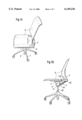
- FIG. 1A shows the perspective view of the chair as a whole
- FIG. 1B shows the side view of the chair according to FIG. 1A;
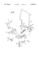
- FIG. 2A shows the frame structure of the chair without padded covering
- FIG. 2B shows an exploded illustration of the frame structure without underframe
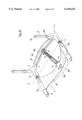
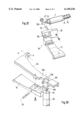
- FIG. 2C shows the perspective view of the seat support with the rear support articulated thereon and the inclination-adjustment pneumatic spring
- FIG. 2D shows a partial section of the changeover lever which is arranged in the seat support and is intended for the height-adjustment pneumatic spring
- FIG. 2E shows the changeover lever which is arranged in the seat support and is intended for the inclination-adjustment pneumatic spring
- FIG. 2F shows a sectional illustration of the changeover lever according to FIG. 2E
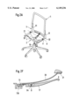
- FIG. 3A shows a partial section of the frame structure with padded covering fitted thereon
- FIG. 3B shows a partial section of the padded covering in the region of the seat support
- FIG. 3C shows the fastening of the padded covering on the crossmember of the rear support as a sectional illustration
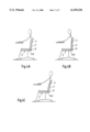
- FIG. 4A shows a basic illustration of the chair in the basic position (posterior support horizontal, backrest vertical);
- FIG. 4B shows a basic illustration of the chair in the writing position (posterior support and backrest inclined in the forward direction), and
- FIG. 4C shows a basic illustration of the chair in the relaxing position (posterior support and backrest inclined in the rearward direction).
- the chair is made up, in principle, of the star-shaped underframe 1, the seat support 2, the rear support 3, the rear tensioner 4, the adjusting mechanism 5, the height-adjustment pneumatic spring 6, the inclination-adjustment pneumatic spring 7 and the padded covering 8.
- Extending from the underframe 1 is a centrally arranged middle column 10 which rises up vertically and in which there is inserted the height-adjustment pneumatic spring 6 for height-adjustment purposes.
- the seat support 2 is positioned on the top, conical end of the extensible piston rod 60 of the height-adjustment pneumatic spring 6.
- the seat support 2, the rear support 3 and the rear tensioner 4 are covered by the single-piece padded covering S.
- the obliquely upwardly rising inclination-adjustment pneumatic spring 7 is articulated in the axis of rotation D1.
- the other end of the inclination-adjustment pneumatic spring 7 is articulated centrally on the crossmember 30 of the rear support 3, this resulting in the axis of rotation D2.
- Extending to the outside of the crossmember 30 are two vertical supports 31, which rise upward, and two horizontal arms-32, which project virtually at right angles, this resulting in a single-piece rear support 3.
- the arms 32 are connected to the seat support 2 in hinge connections V, with the result that the main axis of rotation D is formed here, it being possible for the rear support 3 to be pivoted as a whole about said main axis of rotation.
- the region between the main axis of rotation D and the crossmember 30 constitutes the posterior support G.
- the bracket-like rear tensioner 4 is fastened on the supports 31.
- the single-piece, solid seat support 2 essentially comprises a bracket part 20 which is bent open in the upward direction and has support strips 21 which each adjoin at right angles on the outside, are oriented in the forward direction and are rejoined at the rear by the arms 32 in the hinge connections V.
- a through-passage 200 is located in the center of the base of the bracket part 20.
- the support strips 21 contain pairs of screw holes 210,211 in order to fasten on said support strips the ruler-like seat tensioners 22 and, as appropriate, the armrests 9 which are to be fitted.
- the seat tensioners 22 thus contain screw holes 220 which correspond with the screw holes 211 in the support strips.
- the through-passage 200 which is provided on the base of the bracket part 20, has a round bore 201 and an adjoining groove 202, this resulting in a configuration similar to a keyhole.
- the inclination-adjustment pneumatic spring 7 is articulated on the crossmember 30 in a set-back section 300.
- a helical spring 71 is additionally positioned on the piston rod 70 of the inclination-adjustment pneumatic spring 7.
- a groove 301 which runs longitudinally on the crossmember 30 and is intended for receiving the tensioning bolts 302 used for fastening the padded covering 8.
- a positioning shoulder 310 which is directed toward the arms 32, and bores 311.
- the changeover levers 16,17 for the purpose of actuating the height-adjustment pneumatic spring 6 and the inclination-adjustment pneumatic spring 7, respectively, are arranged beneath the bracket part 20, in accordance with the shaping of the latter.
- the top part of the height-adjustment pneumatic spring 6 with the upwardly projecting valve stem 62 is seated in the conical bore 201 of the through-passage 200 of the bracket part 20.
- the associated changeover lever 16 has a nose 160 and is fixed in an axis of rotation D3.
- the nose 160 projects, through the groove 202 of the through-passage 200, into the bore 201 of the latter and is located directly above the valve stem 62. If the changeover lever 16 is drawn upward toward the bracket part 20, then the nose 160 moves downward and pushes on the valve stem 62.
- the changeover lever 17 for the purpose of actuating the valve stem 72, which projects out of the inclination-adjustment pneumatic spring 7, is fitted, analogously to the lever 16, in an axis of rotation D4.
- a deflecting angle 73 which is inserted rotatably in the bracket part 20 and on which a catch 730 is located.
- the single-piece padded covering 3 extends from the seat support 2, via the posterior support G of the latter, to the crossmember 30 and over the rear tensioner 4.
- the padded covering 8 has a pocket 80, into which the seat tensioners 22 are pushed.
- These ruler-like or strip-like seat tensioners 22 are then fastened on the support strips 21, and are preferably screwed from beneath through the bores 211,220.
- Cutouts 81 are provided in the padded covering 8 in the region of the hinge connections V and of the crossover points of crossmember 30, vertical supports 31 and arms 32.
- the padded covering 8 has a branching arrangement 82 from which the padded covering 8 extends further to the rear tensioner 4 and where a strip-like extension 83 is provided.
- the branching arrangement 82 and the extension 83 may be produced by a second piece of fabric being sewn on.
- the padded covering 8 also has a pocket in the region of the rear tensioner 4, and the loose rear tensioner 4 can be pushed into said pocket.
- the rear tensioner 4, inserted in the padded covering 8 in this way, is then fastened on the vertical supports 31, i.e. positioned and fixed, preferably screwed from the rear, on the positioning shoulders 310.
- the screw holes 311 and 40 in the vertical supports 31 and in the rear tensioner 4, respectively, are used for this purpose.
- the attachment 83 is folded downward around the crossmember 30, the tensioning bolts 302 being seated in the grooves 301 and fixed therein, erg. by means of screws 303.
- the desired chair height can only be adjusted if the changeover lever 16 is pushed and thus the length of excursion of the height-adjustment pneumatic spring 6 can be changed.
- the actuating lever 16 is pushed and the seat support 2 is relieved of loading, said seat support is raised to the maximum height. If the seat support 2 has been subjected to loading and the changeover lever 16 has been pushed, then the seat support 2 is moved downward to the lowermost position.
- the current position is locked, i.e. the inclination-adjustment pneumatic spring 1 is blocked.
- the blocking of the inclination adjustment pneumatic spring 7 is canceled and the user, by shifting his/her body weight, can assume, on the chair, any position in the entire range between the forwardly inclined, writing position (according to FIG. 4B), via the central, basic position (according to FIG. 4A), to the rearwardly inclined, relaxing position (according to FIG. 4C).
- the changeover lever 17 is operated anew, the current position is locked again.
- inclination-adjustment pneumatic spring 7 If the inclination-adjustment pneumatic spring 7 is in the free state, and the user exerts sufficient pressure against the back part, this results in a movement in the main axis of rotation D and the secondary axes of rotation D1 and D2.
- the inclination-adjustment pneumatic spring 7 and the helical spring 71 change their lengths of excursion. An adequate change in the posterior support follows when the rear support 3 is adjusted in terms of inclination.
Abstract
Description
Claims (11)
Applications Claiming Priority (3)
| Application Number | Priority Date | Filing Date | Title |
|---|---|---|---|
| CH250796 | 1996-10-14 | ||
| CH2507/96 | 1996-10-14 | ||
| PCT/IB1997/001202 WO1998016140A1 (en) | 1996-10-14 | 1997-10-03 | Chair frame, control mechanism and upholstery |
Publications (1)
| Publication Number | Publication Date |
|---|---|
| US6149236A true US6149236A (en) | 2000-11-21 |
Family
ID=4235354
Family Applications (1)
| Application Number | Title | Priority Date | Filing Date |
|---|---|---|---|
| US09/284,393 Expired - Fee Related US6149236A (en) | 1996-10-14 | 1997-10-03 | Chair frame, control mechanism and upholstery |
Country Status (7)
| Country | Link |
|---|---|
| US (1) | US6149236A (en) |
| EP (1) | EP0949875B1 (en) |
| JP (1) | JP3278170B2 (en) |
| AT (1) | ATE209011T1 (en) |
| AU (1) | AU4315397A (en) |
| DE (1) | DE59706076D1 (en) |
| WO (1) | WO1998016140A1 (en) |
Cited By (43)
| Publication number | Priority date | Publication date | Assignee | Title |
|---|---|---|---|---|
| US6637072B2 (en) | 2000-09-29 | 2003-10-28 | Formway Furniture Limited | Castored base for an office chair |
| US6715834B1 (en) * | 2003-07-15 | 2004-04-06 | Simon Liao | Angle adjusting device for a chair |
| US6739664B2 (en) * | 2000-10-16 | 2004-05-25 | Kokuyo Co., Ltd. | Chair |
| US20040130197A1 (en) * | 2002-12-31 | 2004-07-08 | Metalseat Srl | Locking device for an office chair structure with an articulation permitting the movement of the seat and the seat back and related structures of the chair |
| US6802566B2 (en) | 2000-09-28 | 2004-10-12 | Formway Furniture Limited | Arm assembly for a chair |
| US20040245828A1 (en) * | 2003-06-05 | 2004-12-09 | Norman Christopher J. | Seating unit with crossbar seat support |
| US20050029848A1 (en) * | 2002-09-12 | 2005-02-10 | Heidmann Kurt R. | Seating unit having motion control |
| US20050082891A1 (en) * | 2002-01-17 | 2005-04-21 | Lor Lean S. | Dining chair with reclining mechanism |
| US6913316B2 (en) * | 2000-10-16 | 2005-07-05 | Kokuyo Co., Ltd. | Chair |
| EP1576904A1 (en) * | 2004-03-18 | 2005-09-21 | Pro-Cord S.P.A. | A chair with oscillating backrest |
| US20050264060A1 (en) * | 2004-05-28 | 2005-12-01 | William Cesaroni | Versatile chair |
| US20060181128A1 (en) * | 2005-02-02 | 2006-08-17 | Hiroshi Takeuchi | Chair and support mechanism unit thereof |
| US20060202535A1 (en) * | 2005-03-08 | 2006-09-14 | Heidmann Kurt R | Seating with shape-changing back support frame |
| US20070108831A1 (en) * | 2005-11-11 | 2007-05-17 | Kokuyo Furniture Co., Ltd. | Structure for connecting members |
| US20070108821A1 (en) * | 2005-11-11 | 2007-05-17 | Kokuyo Furniture Co.,Ltd. | Chair |
| US20070108819A1 (en) * | 2005-11-11 | 2007-05-17 | Kokuyo Furniture Co., Ltd. | Chair |
| US20070108822A1 (en) * | 2005-11-11 | 2007-05-17 | Kokuyo Furniture Co., Ltd. | Chair |
| US20070278837A1 (en) * | 2006-10-13 | 2007-12-06 | L & P Property Management Company | Reclining back mechanism for a seating unit |
| US20080252124A1 (en) * | 2007-04-13 | 2008-10-16 | Chen Yung-Hua | Apparatus for adjusting the angle of a seat back of an office chair |
| US20100141002A1 (en) * | 2008-06-04 | 2010-06-10 | Kurrasch Andrew J | Biasing mechanism |
| US20100176636A1 (en) * | 2009-01-09 | 2010-07-15 | Chun-Chang Tai | Buffering device for chair |
| US20100187883A1 (en) * | 2009-01-23 | 2010-07-29 | Chen Yung-Hua | Apparatus for adjusting the seat back angle |
| US20100244522A1 (en) * | 2009-03-27 | 2010-09-30 | Oki Electric Industry Co., Ltd. | Chair providing more comfortable when seated in optimum posture while reclining |
| US7857388B2 (en) | 2007-06-01 | 2010-12-28 | Steelcase Inc. | Seating unit with adjustable lumbar device |
| CN1823657B (en) * | 2005-02-02 | 2011-11-23 | 伊藤喜有限公司 | Chair and support mechanism unit thereof |
| US20120139318A1 (en) * | 2010-12-07 | 2012-06-07 | Chuen-Jong Tseng | Chair |
| US20130278034A1 (en) * | 2012-04-23 | 2013-10-24 | Lerado (Zhong Shan) Industrial Co., Ltd. | Space adjustment mechanism for a chair |
| USD703988S1 (en) | 2013-06-07 | 2014-05-06 | Steelcase Inc. | Chair |
| USD703987S1 (en) | 2013-06-07 | 2014-05-06 | Steelcase Inc. | Chair |
| USD704487S1 (en) | 2013-06-07 | 2014-05-13 | Steelcase Inc. | Chair |
| USD704945S1 (en) | 2013-05-16 | 2014-05-20 | Steelcase Inc. | Chair |
| USD705561S1 (en) | 2013-05-16 | 2014-05-27 | Steelcase Inc. | Chair |
| USD706547S1 (en) | 2013-06-07 | 2014-06-10 | Steelcase Inc. | Chair |
| USD707976S1 (en) | 2013-06-07 | 2014-07-01 | Steelcase Inc. | Chair |
| USD708466S1 (en) | 2013-05-16 | 2014-07-08 | Steelcase Inc. | Chair |
| USD721529S1 (en) | 2013-06-07 | 2015-01-27 | Steelcase Inc. | Handle apparatus |
| USD760525S1 (en) | 2015-04-21 | 2016-07-05 | Pro-Cord S.P.A. | Chair |
| USD761606S1 (en) | 2015-04-21 | 2016-07-19 | Pro-Cord S.P.A. | Two-color chair |
| USD764849S1 (en) | 2015-04-21 | 2016-08-30 | Pro-Cord S.P.A. | Chair |
| US10028586B2 (en) * | 2012-10-18 | 2018-07-24 | Vitra Patente Ag | Seat with relative synchronous displacement between back incline and seat incline |
| USD864641S1 (en) * | 2016-06-10 | 2019-10-29 | Bock 1 Gmbh & Co. Kg | Office chair |
| US20200352337A1 (en) * | 2018-01-09 | 2020-11-12 | Superseating Bvba | Seating assembly for improved seating, ergonomic chairs or wheelchairs |
| DE102020110707A1 (en) | 2020-04-20 | 2021-10-21 | Bock 1 Gmbh & Co. Kg | Seating |
Families Citing this family (12)
| Publication number | Priority date | Publication date | Assignee | Title |
|---|---|---|---|---|
| WO2000022960A1 (en) | 1998-10-21 | 2000-04-27 | Vitra Patente Ag | Adjustment mechanism, back cover and arm rest for a chair |
| ATE352231T1 (en) | 2000-10-12 | 2007-02-15 | Vitra Patente Ag | STORAGE FOR ONE SEAT |
| JP4750401B2 (en) * | 2004-10-29 | 2011-08-17 | 株式会社イトーキ | Chair |
| JP2006212152A (en) * | 2005-02-02 | 2006-08-17 | Itoki Corp | Chair |
| JP4037438B2 (en) | 2006-06-29 | 2008-01-23 | 沖電気工業株式会社 | Chair |
| CA2665176C (en) | 2006-10-04 | 2016-01-19 | Formway Furniture Limited | A back portion for a chair with a moveable upper section |
| CN101980841B (en) | 2008-04-08 | 2013-07-17 | 佛姆维家具有限公司 | Injection moulding method |
| DE102009022994B4 (en) * | 2008-05-28 | 2020-02-27 | Suspa Gmbh | Backrest adjustment device |
| JP4379538B1 (en) | 2008-10-07 | 2009-12-09 | 沖電気工業株式会社 | Link mechanism for chair, chair |
| CN108056613B (en) * | 2017-01-19 | 2021-04-23 | 安吉县盛信办公家具有限公司 | Waist support seat |
| CN206822374U (en) * | 2017-01-19 | 2018-01-02 | 欧亚平 | A kind of backrest can be close to the chair of human waist and back movement |
| US11284722B1 (en) * | 2021-05-24 | 2022-03-29 | Alexander Chan | Folding chair |
Citations (9)
| Publication number | Priority date | Publication date | Assignee | Title |
|---|---|---|---|---|
| DE2434104A1 (en) * | 1973-08-20 | 1975-02-27 | Fehlbaum Fa | UPHOLSTERED FURNITURE WITH ADJUSTABLE SEAT AND BACK SUPPORT |
| CH582498A5 (en) * | 1974-09-06 | 1976-12-15 | Fehlbaum Fa | |
| US4408800A (en) * | 1980-06-11 | 1983-10-11 | American Seating Company | Office chairs |
| US4521053A (en) * | 1981-06-23 | 1985-06-04 | Gispen+Staalmeubel B.V. | Chair |
| US4589697A (en) * | 1983-09-30 | 1986-05-20 | Fritz Bauer & Sohne Ohg | Bearing device for a chair with incline-adjustable back-rest bearer and incline-adjustable seat |
| CA1224708A (en) * | 1983-06-07 | 1987-07-28 | Heinrich Korn | Chair |
| US5069496A (en) * | 1988-10-14 | 1991-12-03 | Kunh Guenther | Chair with adjustable seat and back rest |
| US5577804A (en) * | 1995-06-30 | 1996-11-26 | Global Upholstery Company | Seat height adjustment mechanism for a chair |
| US5725276A (en) * | 1995-06-07 | 1998-03-10 | Ginat; Jonathan | Tilt back chair and control |
-
1997
- 1997-10-03 WO PCT/IB1997/001202 patent/WO1998016140A1/en active IP Right Grant
- 1997-10-03 AT AT97941142T patent/ATE209011T1/en not_active IP Right Cessation
- 1997-10-03 JP JP51813498A patent/JP3278170B2/en not_active Expired - Fee Related
- 1997-10-03 DE DE59706076T patent/DE59706076D1/en not_active Expired - Lifetime
- 1997-10-03 EP EP97941142A patent/EP0949875B1/en not_active Expired - Lifetime
- 1997-10-03 US US09/284,393 patent/US6149236A/en not_active Expired - Fee Related
- 1997-10-03 AU AU43153/97A patent/AU4315397A/en not_active Abandoned
Patent Citations (10)
| Publication number | Priority date | Publication date | Assignee | Title |
|---|---|---|---|---|
| DE2434104A1 (en) * | 1973-08-20 | 1975-02-27 | Fehlbaum Fa | UPHOLSTERED FURNITURE WITH ADJUSTABLE SEAT AND BACK SUPPORT |
| CH568738A5 (en) * | 1973-08-20 | 1975-11-14 | Fehlbaum Fa | |
| CH582498A5 (en) * | 1974-09-06 | 1976-12-15 | Fehlbaum Fa | |
| US4408800A (en) * | 1980-06-11 | 1983-10-11 | American Seating Company | Office chairs |
| US4521053A (en) * | 1981-06-23 | 1985-06-04 | Gispen+Staalmeubel B.V. | Chair |
| CA1224708A (en) * | 1983-06-07 | 1987-07-28 | Heinrich Korn | Chair |
| US4589697A (en) * | 1983-09-30 | 1986-05-20 | Fritz Bauer & Sohne Ohg | Bearing device for a chair with incline-adjustable back-rest bearer and incline-adjustable seat |
| US5069496A (en) * | 1988-10-14 | 1991-12-03 | Kunh Guenther | Chair with adjustable seat and back rest |
| US5725276A (en) * | 1995-06-07 | 1998-03-10 | Ginat; Jonathan | Tilt back chair and control |
| US5577804A (en) * | 1995-06-30 | 1996-11-26 | Global Upholstery Company | Seat height adjustment mechanism for a chair |
Cited By (67)
| Publication number | Priority date | Publication date | Assignee | Title |
|---|---|---|---|---|
| US7798573B2 (en) | 2000-09-28 | 2010-09-21 | Formway Furniture Limited | Reclinable chair |
| US6802566B2 (en) | 2000-09-28 | 2004-10-12 | Formway Furniture Limited | Arm assembly for a chair |
| US6817667B2 (en) | 2000-09-28 | 2004-11-16 | Formway Furniture Limited | Reclinable chair |
| US6637072B2 (en) | 2000-09-29 | 2003-10-28 | Formway Furniture Limited | Castored base for an office chair |
| US6739664B2 (en) * | 2000-10-16 | 2004-05-25 | Kokuyo Co., Ltd. | Chair |
| US6913316B2 (en) * | 2000-10-16 | 2005-07-05 | Kokuyo Co., Ltd. | Chair |
| US20050082891A1 (en) * | 2002-01-17 | 2005-04-21 | Lor Lean S. | Dining chair with reclining mechanism |
| US20070278841A1 (en) * | 2002-01-17 | 2007-12-06 | Lor Lean S | backpost unit of wooden dining chair with reclining mechanism |
| US7416252B2 (en) * | 2002-01-17 | 2008-08-26 | Green Continental Furniture (M) Sdn Bhd | Backpost unit of wooden dining chair with reclining mechanism |
| US6869142B2 (en) | 2002-09-12 | 2005-03-22 | Steelcase Development Corporation | Seating unit having motion control |
| US20050029848A1 (en) * | 2002-09-12 | 2005-02-10 | Heidmann Kurt R. | Seating unit having motion control |
| US6957863B2 (en) | 2002-09-12 | 2005-10-25 | Steelcase Development Corporation | Seating unit having motion control |
| US20060055220A1 (en) * | 2002-09-12 | 2006-03-16 | Heidmann Kurt R | Seating unit with novel flexible supports |
| US7234774B2 (en) | 2002-09-12 | 2007-06-26 | Steelcase Development Corporation | Seating unit with novel flexible supports |
| US7198328B2 (en) * | 2002-12-31 | 2007-04-03 | Metalseat Srl | Locking device for an office chair structure with an articulation permitting the movement of the seat and the seat back and related structures of the chair |
| US20040130197A1 (en) * | 2002-12-31 | 2004-07-08 | Metalseat Srl | Locking device for an office chair structure with an articulation permitting the movement of the seat and the seat back and related structures of the chair |
| US20040245828A1 (en) * | 2003-06-05 | 2004-12-09 | Norman Christopher J. | Seating unit with crossbar seat support |
| US7048335B2 (en) | 2003-06-05 | 2006-05-23 | Steelcase Development Corporation | Seating unit with crossbar seat support |
| US6715834B1 (en) * | 2003-07-15 | 2004-04-06 | Simon Liao | Angle adjusting device for a chair |
| EP1576904A1 (en) * | 2004-03-18 | 2005-09-21 | Pro-Cord S.P.A. | A chair with oscillating backrest |
| US7147286B2 (en) | 2004-05-28 | 2006-12-12 | Hni Technologies Inc. | Versatile chair |
| US20050264060A1 (en) * | 2004-05-28 | 2005-12-01 | William Cesaroni | Versatile chair |
| CN1823657B (en) * | 2005-02-02 | 2011-11-23 | 伊藤喜有限公司 | Chair and support mechanism unit thereof |
| US20060181128A1 (en) * | 2005-02-02 | 2006-08-17 | Hiroshi Takeuchi | Chair and support mechanism unit thereof |
| US7293833B2 (en) * | 2005-02-02 | 2007-11-13 | Itoki Corporation | Chair and support mechanism unit thereof |
| US7686399B2 (en) | 2005-03-08 | 2010-03-30 | Steelcase Inc. | Seating with shape-changing back support frame |
| US7422287B2 (en) * | 2005-03-08 | 2008-09-09 | Steelcase Inc. | Seating with shape-changing back support frame |
| US20060202535A1 (en) * | 2005-03-08 | 2006-09-14 | Heidmann Kurt R | Seating with shape-changing back support frame |
| US20090058160A1 (en) * | 2005-03-08 | 2009-03-05 | Heidmann Kurt R | Seating with shape-changing back support frame |
| US7665805B2 (en) | 2005-11-11 | 2010-02-23 | Kokuyo Furniture Co., Ltd. | Chair |
| US7862120B2 (en) * | 2005-11-11 | 2011-01-04 | Kokuyo Furniture Co., Ltd. | Chair |
| US20070108819A1 (en) * | 2005-11-11 | 2007-05-17 | Kokuyo Furniture Co., Ltd. | Chair |
| US20070108831A1 (en) * | 2005-11-11 | 2007-05-17 | Kokuyo Furniture Co., Ltd. | Structure for connecting members |
| US20070108821A1 (en) * | 2005-11-11 | 2007-05-17 | Kokuyo Furniture Co.,Ltd. | Chair |
| US7712833B2 (en) | 2005-11-11 | 2010-05-11 | Kokuyo Furniture Co., Ltd. | Structure for connecting members |
| US7717513B2 (en) | 2005-11-11 | 2010-05-18 | Kokuyo Furniture Co., Ltd. | Chair |
| US7857389B2 (en) | 2005-11-11 | 2010-12-28 | Kokuyo Furniture Co., Ltd | Structure for connecting members |
| US20070108822A1 (en) * | 2005-11-11 | 2007-05-17 | Kokuyo Furniture Co., Ltd. | Chair |
| US7708346B2 (en) | 2006-10-13 | 2010-05-04 | L&P Property Management Company | Reclining back mechanism for a seating unit |
| US20070278837A1 (en) * | 2006-10-13 | 2007-12-06 | L & P Property Management Company | Reclining back mechanism for a seating unit |
| US20080252124A1 (en) * | 2007-04-13 | 2008-10-16 | Chen Yung-Hua | Apparatus for adjusting the angle of a seat back of an office chair |
| US7857388B2 (en) | 2007-06-01 | 2010-12-28 | Steelcase Inc. | Seating unit with adjustable lumbar device |
| US20100141002A1 (en) * | 2008-06-04 | 2010-06-10 | Kurrasch Andrew J | Biasing mechanism |
| US20100176636A1 (en) * | 2009-01-09 | 2010-07-15 | Chun-Chang Tai | Buffering device for chair |
| US8113586B2 (en) * | 2009-01-23 | 2012-02-14 | Chen Yung-Hua | Apparatus for adjusting the seat back angle |
| US20100187883A1 (en) * | 2009-01-23 | 2010-07-29 | Chen Yung-Hua | Apparatus for adjusting the seat back angle |
| US20100244522A1 (en) * | 2009-03-27 | 2010-09-30 | Oki Electric Industry Co., Ltd. | Chair providing more comfortable when seated in optimum posture while reclining |
| US8177299B2 (en) | 2009-03-27 | 2012-05-15 | Oki Electric Industry Co., Ltd. | Chair more comfortable when seated in optimum posture while reclining |
| US20120139318A1 (en) * | 2010-12-07 | 2012-06-07 | Chuen-Jong Tseng | Chair |
| US20130278034A1 (en) * | 2012-04-23 | 2013-10-24 | Lerado (Zhong Shan) Industrial Co., Ltd. | Space adjustment mechanism for a chair |
| US9049945B2 (en) * | 2012-04-23 | 2015-06-09 | Lerado (Zhong Shan) Industrial Co., Ltd. | Space adjustment mechanism for a chair |
| US10028586B2 (en) * | 2012-10-18 | 2018-07-24 | Vitra Patente Ag | Seat with relative synchronous displacement between back incline and seat incline |
| USD708466S1 (en) | 2013-05-16 | 2014-07-08 | Steelcase Inc. | Chair |
| USD704945S1 (en) | 2013-05-16 | 2014-05-20 | Steelcase Inc. | Chair |
| USD705561S1 (en) | 2013-05-16 | 2014-05-27 | Steelcase Inc. | Chair |
| USD706547S1 (en) | 2013-06-07 | 2014-06-10 | Steelcase Inc. | Chair |
| USD707976S1 (en) | 2013-06-07 | 2014-07-01 | Steelcase Inc. | Chair |
| USD704487S1 (en) | 2013-06-07 | 2014-05-13 | Steelcase Inc. | Chair |
| USD721529S1 (en) | 2013-06-07 | 2015-01-27 | Steelcase Inc. | Handle apparatus |
| USD703987S1 (en) | 2013-06-07 | 2014-05-06 | Steelcase Inc. | Chair |
| USD703988S1 (en) | 2013-06-07 | 2014-05-06 | Steelcase Inc. | Chair |
| USD760525S1 (en) | 2015-04-21 | 2016-07-05 | Pro-Cord S.P.A. | Chair |
| USD761606S1 (en) | 2015-04-21 | 2016-07-19 | Pro-Cord S.P.A. | Two-color chair |
| USD764849S1 (en) | 2015-04-21 | 2016-08-30 | Pro-Cord S.P.A. | Chair |
| USD864641S1 (en) * | 2016-06-10 | 2019-10-29 | Bock 1 Gmbh & Co. Kg | Office chair |
| US20200352337A1 (en) * | 2018-01-09 | 2020-11-12 | Superseating Bvba | Seating assembly for improved seating, ergonomic chairs or wheelchairs |
| DE102020110707A1 (en) | 2020-04-20 | 2021-10-21 | Bock 1 Gmbh & Co. Kg | Seating |
Also Published As
| Publication number | Publication date |
|---|---|
| DE59706076D1 (en) | 2002-02-21 |
| AU4315397A (en) | 1998-05-11 |
| ATE209011T1 (en) | 2001-12-15 |
| WO1998016140A1 (en) | 1998-04-23 |
| EP0949875A1 (en) | 1999-10-20 |
| EP0949875B1 (en) | 2001-11-21 |
| JP3278170B2 (en) | 2002-04-30 |
| JP2000505677A (en) | 2000-05-16 |
Similar Documents
| Publication | Publication Date | Title |
|---|---|---|
| US6149236A (en) | Chair frame, control mechanism and upholstery | |
| US6109694A (en) | Chair with four-bar linkage for self-adjusting back tension | |
| US5765914A (en) | Chair with a tilt control mechanism | |
| US6439661B1 (en) | Chair mechanism | |
| US5108149A (en) | Adjustable seating | |
| US5244253A (en) | Height adjustment control for a chair | |
| US6039397A (en) | Tilt back chair control | |
| US7980631B2 (en) | Ergonomic armrest | |
| US4877291A (en) | Reclining chair | |
| US4840426A (en) | Office chair | |
| US4988145A (en) | Seating furniture | |
| EP0721751B1 (en) | Arrangement in a recline chair | |
| US6572190B2 (en) | Lumbar support for a chair | |
| US6000755A (en) | Swivel chair | |
| US6557939B1 (en) | Adjustment mechanism, back cover and arm rest for a chair | |
| US7552970B2 (en) | Furniture mechanism with tilt cam for multiple position tilt | |
| US20020158496A1 (en) | Swingable chair back with top pivot | |
| CA2565557A1 (en) | Ergonomic chair backrest | |
| US5845961A (en) | Dual leg rest assembly having selectable height ottoman | |
| US6161897A (en) | Chair construction | |
| US7431397B2 (en) | Chair | |
| CN111315260B (en) | Seat module and tilting mechanism | |
| US5121966A (en) | Adjustable recliner chair | |
| JP3080585B2 (en) | Chair | |
| US11006752B2 (en) | Multifunctional balance chair |
Legal Events
| Date | Code | Title | Description |
|---|---|---|---|
| AS | Assignment |
Owner name: PROTONED B.V., NETHERLANDS Free format text: ASSIGNMENT OF ASSIGNORS INTEREST;ASSIGNOR:BRAUNING, EGON;REEL/FRAME:009945/0133 Effective date: 19990308 |
|
| AS | Assignment |
Owner name: VITRA PATENTE AG, SWITZERLAND Free format text: ASSIGNMENT OF ASSIGNORS INTEREST;ASSIGNOR:PROTONED, B.V.;REEL/FRAME:011176/0475 Effective date: 20000818 |
|
| FEPP | Fee payment procedure |
Free format text: PAYOR NUMBER ASSIGNED (ORIGINAL EVENT CODE: ASPN); ENTITY STATUS OF PATENT OWNER: SMALL ENTITY |
|
| FPAY | Fee payment |
Year of fee payment: 4 |
|
| FPAY | Fee payment |
Year of fee payment: 8 |
|
| REMI | Maintenance fee reminder mailed | ||
| LAPS | Lapse for failure to pay maintenance fees | ||
| STCH | Information on status: patent discontinuation |
Free format text: PATENT EXPIRED DUE TO NONPAYMENT OF MAINTENANCE FEES UNDER 37 CFR 1.362 |
|
| FP | Lapsed due to failure to pay maintenance fee |
Effective date: 20121121 |