US6148516A - Metallic cylinder head gasket - Google Patents
Metallic cylinder head gasket Download PDFInfo
- Publication number
- US6148516A US6148516A US09/138,139 US13813998A US6148516A US 6148516 A US6148516 A US 6148516A US 13813998 A US13813998 A US 13813998A US 6148516 A US6148516 A US 6148516A
- Authority
- US
- United States
- Prior art keywords
- deformation limiter
- passage
- deformation
- bead
- carrier plate
- Prior art date
- Legal status (The legal status is an assumption and is not a legal conclusion. Google has not performed a legal analysis and makes no representation as to the accuracy of the status listed.)
- Expired - Lifetime
Links
Images

Classifications
-
- B—PERFORMING OPERATIONS; TRANSPORTING
- B21—MECHANICAL METAL-WORKING WITHOUT ESSENTIALLY REMOVING MATERIAL; PUNCHING METAL
- B21K—MAKING FORGED OR PRESSED METAL PRODUCTS, e.g. HORSE-SHOES, RIVETS, BOLTS OR WHEELS
- B21K23/00—Making other articles
-
- F—MECHANICAL ENGINEERING; LIGHTING; HEATING; WEAPONS; BLASTING
- F02—COMBUSTION ENGINES; HOT-GAS OR COMBUSTION-PRODUCT ENGINE PLANTS
- F02F—CYLINDERS, PISTONS OR CASINGS, FOR COMBUSTION ENGINES; ARRANGEMENTS OF SEALINGS IN COMBUSTION ENGINES
- F02F11/00—Arrangements of sealings in combustion engines
- F02F11/002—Arrangements of sealings in combustion engines involving cylinder heads
-
- F—MECHANICAL ENGINEERING; LIGHTING; HEATING; WEAPONS; BLASTING
- F16—ENGINEERING ELEMENTS AND UNITS; GENERAL MEASURES FOR PRODUCING AND MAINTAINING EFFECTIVE FUNCTIONING OF MACHINES OR INSTALLATIONS; THERMAL INSULATION IN GENERAL
- F16J—PISTONS; CYLINDERS; SEALINGS
- F16J15/00—Sealings
- F16J15/02—Sealings between relatively-stationary surfaces
- F16J15/06—Sealings between relatively-stationary surfaces with solid packing compressed between sealing surfaces
- F16J15/08—Sealings between relatively-stationary surfaces with solid packing compressed between sealing surfaces with exclusively metal packing
- F16J15/0818—Flat gaskets
- F16J15/0825—Flat gaskets laminated
-
- F—MECHANICAL ENGINEERING; LIGHTING; HEATING; WEAPONS; BLASTING
- F02—COMBUSTION ENGINES; HOT-GAS OR COMBUSTION-PRODUCT ENGINE PLANTS
- F02F—CYLINDERS, PISTONS OR CASINGS, FOR COMBUSTION ENGINES; ARRANGEMENTS OF SEALINGS IN COMBUSTION ENGINES
- F02F1/00—Cylinders; Cylinder heads
- F02F1/02—Cylinders; Cylinder heads having cooling means
- F02F1/10—Cylinders; Cylinder heads having cooling means for liquid cooling
- F02F2001/104—Cylinders; Cylinder heads having cooling means for liquid cooling using an open deck, i.e. the water jacket is open at the block top face
-
- F—MECHANICAL ENGINEERING; LIGHTING; HEATING; WEAPONS; BLASTING
- F16—ENGINEERING ELEMENTS AND UNITS; GENERAL MEASURES FOR PRODUCING AND MAINTAINING EFFECTIVE FUNCTIONING OF MACHINES OR INSTALLATIONS; THERMAL INSULATION IN GENERAL
- F16J—PISTONS; CYLINDERS; SEALINGS
- F16J15/00—Sealings
- F16J15/02—Sealings between relatively-stationary surfaces
- F16J15/06—Sealings between relatively-stationary surfaces with solid packing compressed between sealing surfaces
- F16J15/08—Sealings between relatively-stationary surfaces with solid packing compressed between sealing surfaces with exclusively metal packing
- F16J15/0818—Flat gaskets
- F16J2015/0843—Flat gaskets with an edge portion folded over the plate itself
-
- F—MECHANICAL ENGINEERING; LIGHTING; HEATING; WEAPONS; BLASTING
- F16—ENGINEERING ELEMENTS AND UNITS; GENERAL MEASURES FOR PRODUCING AND MAINTAINING EFFECTIVE FUNCTIONING OF MACHINES OR INSTALLATIONS; THERMAL INSULATION IN GENERAL
- F16J—PISTONS; CYLINDERS; SEALINGS
- F16J15/00—Sealings
- F16J15/02—Sealings between relatively-stationary surfaces
- F16J15/06—Sealings between relatively-stationary surfaces with solid packing compressed between sealing surfaces
- F16J15/08—Sealings between relatively-stationary surfaces with solid packing compressed between sealing surfaces with exclusively metal packing
- F16J15/0818—Flat gaskets
- F16J2015/085—Flat gaskets without fold over
-
- F—MECHANICAL ENGINEERING; LIGHTING; HEATING; WEAPONS; BLASTING
- F16—ENGINEERING ELEMENTS AND UNITS; GENERAL MEASURES FOR PRODUCING AND MAINTAINING EFFECTIVE FUNCTIONING OF MACHINES OR INSTALLATIONS; THERMAL INSULATION IN GENERAL
- F16J—PISTONS; CYLINDERS; SEALINGS
- F16J15/00—Sealings
- F16J15/02—Sealings between relatively-stationary surfaces
- F16J15/06—Sealings between relatively-stationary surfaces with solid packing compressed between sealing surfaces
- F16J15/08—Sealings between relatively-stationary surfaces with solid packing compressed between sealing surfaces with exclusively metal packing
- F16J15/0818—Flat gaskets
- F16J2015/0862—Flat gaskets with a bore ring
-
- Y—GENERAL TAGGING OF NEW TECHNOLOGICAL DEVELOPMENTS; GENERAL TAGGING OF CROSS-SECTIONAL TECHNOLOGIES SPANNING OVER SEVERAL SECTIONS OF THE IPC; TECHNICAL SUBJECTS COVERED BY FORMER USPC CROSS-REFERENCE ART COLLECTIONS [XRACs] AND DIGESTS
- Y10—TECHNICAL SUBJECTS COVERED BY FORMER USPC
- Y10T—TECHNICAL SUBJECTS COVERED BY FORMER US CLASSIFICATION
- Y10T29/00—Metal working
- Y10T29/49—Method of mechanical manufacture
- Y10T29/49229—Prime mover or fluid pump making
- Y10T29/49297—Seal or packing making
-
- Y—GENERAL TAGGING OF NEW TECHNOLOGICAL DEVELOPMENTS; GENERAL TAGGING OF CROSS-SECTIONAL TECHNOLOGIES SPANNING OVER SEVERAL SECTIONS OF THE IPC; TECHNICAL SUBJECTS COVERED BY FORMER USPC CROSS-REFERENCE ART COLLECTIONS [XRACs] AND DIGESTS
- Y10—TECHNICAL SUBJECTS COVERED BY FORMER USPC
- Y10T—TECHNICAL SUBJECTS COVERED BY FORMER US CLASSIFICATION
- Y10T29/00—Metal working
- Y10T29/49—Method of mechanical manufacture
- Y10T29/49826—Assembling or joining
- Y10T29/49908—Joining by deforming
Definitions
- the present invention relates to the manufacture of cylinder head gaskets for internal combustion engines and, particularly, to the formation of carrier plates for such gaskets. More specifically, this invention is directed to metallic cylinder head gaskets and, especially, to multilayer gaskets having a carrier plate which includes a deformation limiter. Accordingly, the general objects of the present invention are to provide novel and improved methods and articles of such character.
- EP-C-0 306 766 and EP-C-0 230 804 disclose metallic cylinder head gaskets for internal combustion engines. These prior art gaskets comprise carrier plate which cooperates with at least one cover plate, the cover plate having resilient beads, i.e., deformations, which function as sealing rings.
- the gap at any point between the cylinder head and cylinder block of an internal combustion engine varies during operation as a function of the working cycle of the adjacent cylinder.
- the cylinder head gasket which must seal this variable gap, is subjected to constant changes in pressure and must have permanent resilient properties in order to maintain a satisfactory seal.
- the seal established by the gaskets of the above-identified references is created by upward extensions of the cylinder head gasket, such extensions being disposed about the combustion spaces, and the beads.
- the beads act as spring elements and follow vertical relative movements of the cylinder head in relation to the cylinder block which occur as a result of cylinder pressure variations.
- no unacceptably large deformation of a sealing bead must occur when the bead is subjected to maximum load.
- the relief of the applied, i.e., clamping, force must not be complete but rather only take place to such an extent that a minimum deformation occurs.
- the working range of the bead lies between these two limit points of the deformation.
- the beads In order to ensure proper functioning thereof, the beads must not be completely deformed either during the installation of the gasket or in the operating state. An unacceptably large deformation of a bead vertically with respect to the plane of the gasket is prevented in known gaskets by means of a deformation limiter of constant thickness.
- the deformation limiters also serve to extend the gasket upwardly along the combustion space.
- Translatory movements can occur between the cylinder block and the cylinder head when these engine components have coefficients of thermal expansion, a cast iron block combined with a light weight, i.e., aluminum, metal head, for example. Translatory movements can also occur if the cooling conditions are different. Translatory movements lead to erosion created leakage paths, particularly on the cylinder head.
- an object of the invention is to provide a metallic cylinder head gasket, and a method of fabrication thereof, in which the maximum acceptable deformation of the bead is not exceeded even over relatively long operation.
- Another object of the invention is to provide a metallic cylinder head gasket designed to eliminate the formation of leakage channels in the cylinder head.
- the inner deformation limiters are provided, on the side thereof which faces the combustion space passage, at the edges facing the cover plates, with rounded portions of sufficient radius to ensure that no high edge pressures occur.
- Gaskets in accordance with the invention can be manufactured without large financial outlay for specialized equipment and without additional components. During manufacture, a convex shape may easily be imparted to both sides of the deformation limiter.
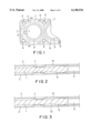
- FIG. 1 is a partial schematic plan view of a portion of a cylinder head gasket in accordance with a first embodiment of the invention
- FIG. 2 is a cross-sectional view of the head gasket of FIG. 1 taken along the line I--I;
- FIG. 3 is a cross-sectional view of a gasket in accordance with a second embodiment of the invention.
- FIG. 4 is a cross-sectional view of a gasket in accordance with a third embodiment of the invention.
- FIG. 5 is a cross-sectional view of a gasket in accordance with a fourth embodiment of the invention.
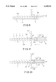
- FIG. 6 is a cross-sectional view, partially in phantom, schematically illustrating an initial step in a method for manufacturing a gasket carrier plate in accordance with the invention
- FIG. 7 is a cross-sectional view, partially in phantom, of a manufacturing step performed subsequent to the step of FIG. 6;
- FIG. 8 is a cross-sectional view schematically illustrating an alternative method of manufacturing a carrier plate for a gasket in accordance with the invention.
- FIG. 9 is a partial cross-sectional view of a step of a further alternative method of manufacturing a head gasket in accordance with the invention.
- FIG. 10 is a partial cross-sectional view of a subsequent step in the performance of the method of FIG. 9.
- the multilayer, metallic cylinder head gasket illustrated in FIGS. 1 and 2 comprises an intermediate carrier member 1, in the form of a generally planar sheet or plate, disposed between a pair of identical cover plates 2.
- the gasket comprising the carrier plate 1 and the cover plates 2, defines a series of combustion space passages 3 which correspond to the cylinder bores of the internal combustion engine on which the gasket is to be installed.
- the gasket further defines holes 4 for the bolts which are used to clamp the cylinder head to the engine block.
- the gasket also defines openings 5, 6 through which coolant and oil will flow.
- the cover plates 2 are usually manufactured from thin sheets of spring steel.
- the cover plates 2 are provided with resilient beads 7 which extend around, and are spaced from, the combustion space passages 3.
- the spacing or set back of each bead 7 leaves an annular, straight plate section or rim 8 in the edge area of each combustion space passage 3.
- the beads 7 are in the form of arcuate deformations of the sheet material which extend in the direction of the carrier plate 1.
- the beads 7 on the two cover plates 2 are generally in registration.
- half-beads (not illustrated) are usually provided on the cover plates 2 around the openings 5, 6 and the bolt holes 4.
- the carrier plate 1, which is otherwise planar, is provided with a deformation limiter 9 in the peripheral area which extends about each of the combustion space passages 3.
- deformation limiters are for the purpose of protecting an adjacent bead 7 against excessive compressive stress.
- a deformation limiter 9 is in the form of a thickened portion of the carrier plate 1 adjacent to the edge of the combustion space passage 3 and outside of the bead area, i.e., between the bead 7 and the combustion space passage 3 which the bead seals.
- the deformation limiter 9 is provided with a convex surface on both sides.
- the limiter 9 is formed in such a way that it extends out of the plane of plate 1 approximately the same distance toward each of the cover plates 2. Accordingly, deformation limiter 9 has the same effect on the beads 7 on each of cover plates 2.
- the thickness of the deformation limiter 9 is chosen such that the straight plate sections 8 of the cover plates 2 come to rest on the deformation limiter 9 when the gasket is clamped between the engine block and cylinder head, i.e., at the same time the beads 7 are pressure-loaded. A serial, i.e., double seal is thus established. Also, as a result of the convex construction of the deformation limiter 9, high edge pressures are avoided. High edge pressures lead to leakage channels, particularly in the case of aluminum components, as a result of translatory movements between the cylinder head and cylinder block.
- the carrier plate 1 is provided on each of its two opposed surfaces with a notch 10.
- the notches 10 are located between the deformation limiter 9 and the beads 7 and extend around the deformation limiter 9. As disclosed below, the notches 10 are provided for reasons of the manufacturing process.
- the annular deformation limiter 9 is constructed separately from the carrier plate 1.
- the deformation limiter defining member in the form of a ring 9, is inserted between the cover plates 2 and into a cut-out of the carrier plate 1 of an appropriate size.
- the deformation limiter 9 is partially formed integrally with the carrier plate 1.
- the integral portion of deformation limiter 9 is formed on one side of plate 1, typically the side which faces towards the cylinder head in the installed state of the gasket, and has a convex surface.
- the opposite side of the plate 1, in the region of deformation limiter 9, is provided with an annular, step-shaped recess 11.
- An additional intermediate plate 13, having a folded-over section 12, is partly received in the recess 11.
- the intermediate plate 13 is sandwiched between the carrier plate 1 and the surface of the cover plate 2 which faces the step-shaped recess 11.
- the folded-over section 12 defines a rounded edge portion 14 which faces passage 3 for reducing the edge pressures.
- the deformation limiter 9 determines the limit points of the bead working range according to prescribed operating points. It is possible for vertical and/or width profiling of the deformation limiter 9 to be provided along the circumference of the combustion space passage 3 for the purpose of adapting it to prescribed operating points.
- the height of the deformation limiter 9 will be less than in the areas located intermediate the points of clamp pressure application. Furthermore, given width profiling, in the area adjacent to the bolt holes 4, the width of the deformation limiter 9 is less than in the intermediate areas.
- the support area of the cover plates 2 can also be varied by means, for example, of a correspondingly oval cutout for the combustion space passage 3.
- the bead working range can also be homogenized by corresponding deepening and/or increasing of the height of the carrier plate 1 in the bead contact area.
- the straight cover plate sections 8 can be made to extend only partially over the deformation limiter 9 or, when clamped, be terminated behind the deformation limiter 9.
- an inner deformation limiter 9 constructed integrally with the carrier plate 1 is illustrated.
- the combustion space passages 3 are provided in the carrier plate 1 in such a manner as to leave a rim which extends into the area of each passage 3.
- the carrier plate 1 is clamped between a drawing die 15 and a drawing block 16.
- the drawing block 16 is pressed, for example with strong spring pressure or hydraulically, against the drawing die 15.
- the drawing block 16 protrudes beyond the edge of the drawing die 15 by approximately the thickness of the wall of the carrier plate 1.
- the protrusion of the drawing block 16 serves to guide a drawing punch 17 which has a bevelled guide edge 18.
- the drawing punch 17 deforms the rim portion of the carrier plate 1 at an angle of approximately 900 with respect to the plane of the carrier plate. During this deformation, the bevelled guide edge 18 prevents the carrier plate 1 from tapering or from being pulled out from between the drawing die 15 and drawing block 16.
- the immobilization of carrier plate 1 is expediently aided by projections 19 on the drawing die 15 and the drawing block 16 which extend around and are located adjacent to the area which will be occupied by the deformation limiter 9.
- the projections 19 form the notches 10 (see FIG. 3). by penetrating into the material of the carrier plate 1.
- the carrier plate 1 is subsequently clamped between a stamping plate 20 and a stamping die 21.
- Projections 22 on the stamping plate 20 and stamping die 19 correspond to the projections 19 of the drawing block 16 and drawing die 15.
- the projections 22 thus engage the notches 10.
- the stamping die 21 protrudes beyond the stamping block 20 according to the desired final radius of the deformation limiter 9.
- the stamping die 21 is provided with a stamping face 23 in accordance with the desired shape of the deformation limiter 9 which is, for example, convex.
- a stamping punch 24 By means of a stamping punch 24, the previously folded rim portion edge is stamped to form the final deformation limiter 9.
- the stamping punch 24 is provided with a stamping face 25 corresponding to the stamping face 23.
- Deformation limiters 9 as shown in FIGS. 2, 3 and 5 can be manufactured as depicted in FIGS. 6 and 7 relative to passage 3 with simultaneous vertical profiling and/or width profiling.
- the material of the carrier plate 1 is prevented from flowing back, i.e., radially outwardly during the stamping, by the projections 22.
- the stamping die 21 can also define the entire negative shape of the carrier plate 1 including the associated deformation limiter or limiters 9.
- the stamping punch 24 forms the desired shape by moving onto the stamping die 21.
- a circumferential recess 26 of very little height can be provided adjacent to the upper inner edge of the stamping die 21.
- the recess 26 can give rise to an easily removable burr of excess material at the deformation limiter 9.
- the carrier plate 1 is clamped between two plates 27, 28.
- the plates 27, 28 may also have projections 22 for the same purpose as described above.
- the plates 27, 28 terminate flush with one another in the area of the combustion space passage 3.
- the carrier plate 1 protrudes outward beyond the termination of plates 27, 28.
- the plates are provided with shaping faces 29 adjacent to the inner edge.
- One or more rolling tools 31, provided with shaping faces 30, are used to form the deformation limiter 9 with a desired cross-sectional shape.
- the deformation limiter 9 of the embodiment in FIG. 4 is preferably produced from wire rings which initially have a round or rectangular cross-sectional shape.
- the wire rings are given a convex form on both sides by stamping.
Abstract
The invention relates to a metallic cylinder head gasket for an internal combustion engine, having a carrier plate which is arranged between cover plates. The carrier plate and cover plates are provided with passages which are commensurate with the combustion chambers of the internal combustion engine. The cover plates are provided, around each passage, with a resilient bead. Adjacent to each bead, and also extending around each passage, is a bead deformation limiter. The deformation limiters are shaped to prevent the occurrence of high edge pressures.
Description
This is a Divisional of U.S. patent application Ser. No. 08/867,694 filed Jun. 4, 1997, U.S. Pat. No. 5,875,548 which in turn is a Divisional of U.S. patent application Ser. No. 08/565,108 filed Nov. 30, 1995.
The present invention relates to the manufacture of cylinder head gaskets for internal combustion engines and, particularly, to the formation of carrier plates for such gaskets. More specifically, this invention is directed to metallic cylinder head gaskets and, especially, to multilayer gaskets having a carrier plate which includes a deformation limiter. Accordingly, the general objects of the present invention are to provide novel and improved methods and articles of such character.
Published European Patent Documents EP-C-0 306 766 and EP-C-0 230 804 disclose metallic cylinder head gaskets for internal combustion engines. These prior art gaskets comprise carrier plate which cooperates with at least one cover plate, the cover plate having resilient beads, i.e., deformations, which function as sealing rings. The gap at any point between the cylinder head and cylinder block of an internal combustion engine varies during operation as a function of the working cycle of the adjacent cylinder. The cylinder head gasket, which must seal this variable gap, is subjected to constant changes in pressure and must have permanent resilient properties in order to maintain a satisfactory seal.
The seal established by the gaskets of the above-identified references is created by upward extensions of the cylinder head gasket, such extensions being disposed about the combustion spaces, and the beads. The beads act as spring elements and follow vertical relative movements of the cylinder head in relation to the cylinder block which occur as a result of cylinder pressure variations. On the one hand, no unacceptably large deformation of a sealing bead must occur when the bead is subjected to maximum load. On the other hand, the relief of the applied, i.e., clamping, force must not be complete but rather only take place to such an extent that a minimum deformation occurs. The working range of the bead lies between these two limit points of the deformation.
In order to ensure proper functioning thereof, the beads must not be completely deformed either during the installation of the gasket or in the operating state. An unacceptably large deformation of a bead vertically with respect to the plane of the gasket is prevented in known gaskets by means of a deformation limiter of constant thickness. The deformation limiters also serve to extend the gasket upwardly along the combustion space.
Translatory movements can occur between the cylinder block and the cylinder head when these engine components have coefficients of thermal expansion, a cast iron block combined with a light weight, i.e., aluminum, metal head, for example. Translatory movements can also occur if the cooling conditions are different. Translatory movements lead to erosion created leakage paths, particularly on the cylinder head.
Published German Patent Document DE-A-4 219 709 discloses deformation limiters of rectangular cross-section produced by extrusion or heading. In the case of extrusion produced limiters, since the material being worked flows in all directions and not only in the desired direction, there are large material stresses with a so-called "frog effect" corresponding to a frog spring. For products formed by heading, a conical die is required. Use of such a die leads to uneven edges and the method is unsuitable for mass production since the product is not formed with precise repeatability.
Therefore, an object of the invention is to provide a metallic cylinder head gasket, and a method of fabrication thereof, in which the maximum acceptable deformation of the bead is not exceeded even over relatively long operation.
Another object of the invention is to provide a metallic cylinder head gasket designed to eliminate the formation of leakage channels in the cylinder head.
The above-stated and other objects of the invention are achieved through the manufacture of a novel metallic cylinder head gasket for an internal combustion engine, the gasket having two outer cover "plates" and a carrier "plate" which is sandwiched between the cover plates. The plates are provided with one or more combustion space passages, which are arranged one next to the other, commensurate with the combustion chambers of an internal combustion engine. Each of the cover plates is provided, in the regions which extend around each combustion space passage, with a generally annular shaped "bead". These resilient beads, in the form of arcuate deformations which extend towards the carrier plate, on the two cover plates are generally in registration. The beads are spaced from, i.e., set back from the edges of, associated combustion space passages. This spacing leaves a straight carrier plate section about the periphery of each passage. To protect each bead, an inner deformation limiter is provided adjacent to the bead, the deformation limiters also extending around each combustion space passage.
The inner deformation limiters are provided, on the side thereof which faces the combustion space passage, at the edges facing the cover plates, with rounded portions of sufficient radius to ensure that no high edge pressures occur. By virtue of the avoidance of high edge pressure, leakage channels resulting from translatory movements between the cylinder block and cylinder head are eliminated.
Gaskets in accordance with the invention can be manufactured without large financial outlay for specialized equipment and without additional components. During manufacture, a convex shape may easily be imparted to both sides of the deformation limiter.
Further refinements of a gasket in accordance with the invention, and in the methods for forming the deformation limiters, will become apparent to those skilled in the art from the description below of the disclosed embodiments.
The invention is explained in greater detail below with reference to exemplary illustrated embodiments. In the drawings, like reference numerals refer to like elements in the figures and:
FIG. 1 is a partial schematic plan view of a portion of a cylinder head gasket in accordance with a first embodiment of the invention;
FIG. 2 is a cross-sectional view of the head gasket of FIG. 1 taken along the line I--I;
FIG. 3 is a cross-sectional view of a gasket in accordance with a second embodiment of the invention;
FIG. 4 is a cross-sectional view of a gasket in accordance with a third embodiment of the invention;
FIG. 5 is a cross-sectional view of a gasket in accordance with a fourth embodiment of the invention;
FIG. 6 is a cross-sectional view, partially in phantom, schematically illustrating an initial step in a method for manufacturing a gasket carrier plate in accordance with the invention;
FIG. 7 is a cross-sectional view, partially in phantom, of a manufacturing step performed subsequent to the step of FIG. 6;
FIG. 8 is a cross-sectional view schematically illustrating an alternative method of manufacturing a carrier plate for a gasket in accordance with the invention;
FIG. 9 is a partial cross-sectional view of a step of a further alternative method of manufacturing a head gasket in accordance with the invention; and
FIG. 10 is a partial cross-sectional view of a subsequent step in the performance of the method of FIG. 9.
The multilayer, metallic cylinder head gasket illustrated in FIGS. 1 and 2 comprises an intermediate carrier member 1, in the form of a generally planar sheet or plate, disposed between a pair of identical cover plates 2. The gasket, comprising the carrier plate 1 and the cover plates 2, defines a series of combustion space passages 3 which correspond to the cylinder bores of the internal combustion engine on which the gasket is to be installed. The gasket further defines holes 4 for the bolts which are used to clamp the cylinder head to the engine block. The gasket also defines openings 5, 6 through which coolant and oil will flow.
The cover plates 2 are usually manufactured from thin sheets of spring steel. The cover plates 2 are provided with resilient beads 7 which extend around, and are spaced from, the combustion space passages 3. The spacing or set back of each bead 7 leaves an annular, straight plate section or rim 8 in the edge area of each combustion space passage 3. The beads 7 are in the form of arcuate deformations of the sheet material which extend in the direction of the carrier plate 1. The beads 7 on the two cover plates 2 are generally in registration.
In addition, half-beads (not illustrated) are usually provided on the cover plates 2 around the openings 5, 6 and the bolt holes 4.
The carrier plate 1, which is otherwise planar, is provided with a deformation limiter 9 in the peripheral area which extends about each of the combustion space passages 3. These deformation limiters are for the purpose of protecting an adjacent bead 7 against excessive compressive stress. With reference to FIG. 2, a deformation limiter 9 is in the form of a thickened portion of the carrier plate 1 adjacent to the edge of the combustion space passage 3 and outside of the bead area, i.e., between the bead 7 and the combustion space passage 3 which the bead seals. The deformation limiter 9 is provided with a convex surface on both sides. The limiter 9 is formed in such a way that it extends out of the plane of plate 1 approximately the same distance toward each of the cover plates 2. Accordingly, deformation limiter 9 has the same effect on the beads 7 on each of cover plates 2.
The thickness of the deformation limiter 9 is chosen such that the straight plate sections 8 of the cover plates 2 come to rest on the deformation limiter 9 when the gasket is clamped between the engine block and cylinder head, i.e., at the same time the beads 7 are pressure-loaded. A serial, i.e., double seal is thus established. Also, as a result of the convex construction of the deformation limiter 9, high edge pressures are avoided. High edge pressures lead to leakage channels, particularly in the case of aluminum components, as a result of translatory movements between the cylinder head and cylinder block.
In the embodiment of FIG. 3, the carrier plate 1 is provided on each of its two opposed surfaces with a notch 10. The notches 10 are located between the deformation limiter 9 and the beads 7 and extend around the deformation limiter 9. As disclosed below, the notches 10 are provided for reasons of the manufacturing process.
With reference to FIG. 4, in yet another embodiment of the invention, the annular deformation limiter 9 is constructed separately from the carrier plate 1. The deformation limiter defining member, in the form of a ring 9, is inserted between the cover plates 2 and into a cut-out of the carrier plate 1 of an appropriate size.
With reference to FIG. 5, in still another embodiment of the invention, the deformation limiter 9 is partially formed integrally with the carrier plate 1. Thus, the integral portion of deformation limiter 9 is formed on one side of plate 1, typically the side which faces towards the cylinder head in the installed state of the gasket, and has a convex surface. The opposite side of the plate 1, in the region of deformation limiter 9, is provided with an annular, step-shaped recess 11. An additional intermediate plate 13, having a folded-over section 12, is partly received in the recess 11. The intermediate plate 13 is sandwiched between the carrier plate 1 and the surface of the cover plate 2 which faces the step-shaped recess 11. The folded-over section 12 defines a rounded edge portion 14 which faces passage 3 for reducing the edge pressures.
The deformation limiter 9 determines the limit points of the bead working range according to prescribed operating points. It is possible for vertical and/or width profiling of the deformation limiter 9 to be provided along the circumference of the combustion space passage 3 for the purpose of adapting it to prescribed operating points.
In areas adjacent to the bolt holes 4, given vertical profiling, the height of the deformation limiter 9 will be less than in the areas located intermediate the points of clamp pressure application. Furthermore, given width profiling, in the area adjacent to the bolt holes 4, the width of the deformation limiter 9 is less than in the intermediate areas.
In further embodiments, instead of directly varying the width of the deformation limiter 9, the support area of the cover plates 2 can also be varied by means, for example, of a correspondingly oval cutout for the combustion space passage 3.
If appropriate, the bead working range can also be homogenized by corresponding deepening and/or increasing of the height of the carrier plate 1 in the bead contact area.
Also, if appropriate, the straight cover plate sections 8 can be made to extend only partially over the deformation limiter 9 or, when clamped, be terminated behind the deformation limiter 9.
With reference to FIGS. 6 and 7, the manufacture of an inner deformation limiter 9 constructed integrally with the carrier plate 1 is illustrated. First, the combustion space passages 3 are provided in the carrier plate 1 in such a manner as to leave a rim which extends into the area of each passage 3. Next, the carrier plate 1 is clamped between a drawing die 15 and a drawing block 16. The drawing block 16 is pressed, for example with strong spring pressure or hydraulically, against the drawing die 15. In the edge area of each combustion space passage 3, the drawing block 16 protrudes beyond the edge of the drawing die 15 by approximately the thickness of the wall of the carrier plate 1. The protrusion of the drawing block 16 serves to guide a drawing punch 17 which has a bevelled guide edge 18. The drawing punch 17 deforms the rim portion of the carrier plate 1 at an angle of approximately 900 with respect to the plane of the carrier plate. During this deformation, the bevelled guide edge 18 prevents the carrier plate 1 from tapering or from being pulled out from between the drawing die 15 and drawing block 16. The immobilization of carrier plate 1 is expediently aided by projections 19 on the drawing die 15 and the drawing block 16 which extend around and are located adjacent to the area which will be occupied by the deformation limiter 9. The projections 19 form the notches 10 (see FIG. 3). by penetrating into the material of the carrier plate 1.
The carrier plate 1 is subsequently clamped between a stamping plate 20 and a stamping die 21. Projections 22 on the stamping plate 20 and stamping die 19 correspond to the projections 19 of the drawing block 16 and drawing die 15. The projections 22 thus engage the notches 10. In the area of the combustion space passages 3, the stamping die 21 protrudes beyond the stamping block 20 according to the desired final radius of the deformation limiter 9. The stamping die 21 is provided with a stamping face 23 in accordance with the desired shape of the deformation limiter 9 which is, for example, convex. By means of a stamping punch 24, the previously folded rim portion edge is stamped to form the final deformation limiter 9. The stamping punch 24 is provided with a stamping face 25 corresponding to the stamping face 23. Deformation limiters 9 as shown in FIGS. 2, 3 and 5 can be manufactured as depicted in FIGS. 6 and 7 relative to passage 3 with simultaneous vertical profiling and/or width profiling. The material of the carrier plate 1 is prevented from flowing back, i.e., radially outwardly during the stamping, by the projections 22.
With reference to FIG. 8, the stamping die 21 can also define the entire negative shape of the carrier plate 1 including the associated deformation limiter or limiters 9. The stamping punch 24 forms the desired shape by moving onto the stamping die 21. In order to absorb possible excess material, a circumferential recess 26 of very little height can be provided adjacent to the upper inner edge of the stamping die 21. The recess 26 can give rise to an easily removable burr of excess material at the deformation limiter 9.
With reference to FIGS. 9 and 10, it is also possible to produce the deformation limiters 9 by rolling. In such a process, the carrier plate 1 is clamped between two plates 27, 28. The plates 27, 28 may also have projections 22 for the same purpose as described above. The plates 27, 28 terminate flush with one another in the area of the combustion space passage 3. The carrier plate 1 protrudes outward beyond the termination of plates 27, 28. The plates are provided with shaping faces 29 adjacent to the inner edge. One or more rolling tools 31, provided with shaping faces 30, are used to form the deformation limiter 9 with a desired cross-sectional shape.
The deformation limiter 9 of the embodiment in FIG. 4 is preferably produced from wire rings which initially have a round or rectangular cross-sectional shape. The wire rings are given a convex form on both sides by stamping.
While preferred embodiments have been shown and described, various modifications and substitutions may be made thereto without departing from the spirit and scope of the invention. Accordingly, it is to be understood that the present invention has been described by way of illustration and not limitation.
Claims (9)
1. A method for manufacturing an inner deformation limiter for a metallic cylinder head gasket, said gasket being of a type having at least one cover plate and a carrier plate, said plates being provided with at least one passage therethrough, said at least one passage being defined by edges of said plates and being commensurate with a combustion chamber of an internal combustion engine;
said at least one cover plate being further provided with a resilient bead extending around each said passage, a planar plate section extending between each said bead and a said passage edge, said beads extending outwardly in a direction which is generally transverse to said planar plate section;
an inner deformation limiter for each said bead, said deformation limiter extending around each said passage, each of said deformation limiter having a thickness greater than the thickness of said carrier plate;
wherein said method comprises the steps of:
forming a wire ring; and
pressing said ring to form a ring-shaped deformation limiter with a substantially rectangular section.
2. The method of claim 1, wherein the wire ring is pressed to a ring-shaped deformation limiter having edges, the edges to be adjacent to the at least one cover plate being bevelled.
3. The method of claim 1, wherein the wire ring is pressed to a ring-shaped deformation limiter being crowned at that side to be directed to said at least one cover plate.
4. The method of claim 1, wherein a wire ring having a flat cross-sectional shape is formed.
5. The method of claim 1, wherein a wire ring having a circular cross-sectional shape is formed.
6. The method of claim 1, wherein the deformation limiter is profiled in accordance with a uniform distribution of forces in the edge area of each said passage.
7. The method of claim 6, wherein the deformation limiter is profiled with respect to its cross-sectional height.
8. The method of claim 6, wherein the deformation limiter is profiled with respect to its cross-sectional width.
9. The method of claim 7, wherein the deformation limiter is profiled with respect to its cross-sectional width.
Priority Applications (1)
| Application Number | Priority Date | Filing Date | Title |
|---|---|---|---|
| US09/138,139 US6148516A (en) | 1995-06-07 | 1998-08-21 | Metallic cylinder head gasket |
Applications Claiming Priority (5)
| Application Number | Priority Date | Filing Date | Title |
|---|---|---|---|
| DE19520695A DE19520695C1 (en) | 1995-06-07 | 1995-06-07 | Metallic cylinder head gasket for IC engine |
| DE19520695 | 1995-06-07 | ||
| US08/565,108 US5695200A (en) | 1995-06-07 | 1995-11-30 | Metallic cylinder head gasket with rounded deformation limiter |
| US08/867,694 US5875548A (en) | 1995-06-07 | 1997-06-04 | Method of making a metallic cylinder head gasket |
| US09/138,139 US6148516A (en) | 1995-06-07 | 1998-08-21 | Metallic cylinder head gasket |
Related Parent Applications (1)
| Application Number | Title | Priority Date | Filing Date |
|---|---|---|---|
| US08/867,694 Division US5875548A (en) | 1995-06-07 | 1997-06-04 | Method of making a metallic cylinder head gasket |
Publications (1)
| Publication Number | Publication Date |
|---|---|
| US6148516A true US6148516A (en) | 2000-11-21 |
Family
ID=7763777
Family Applications (3)
| Application Number | Title | Priority Date | Filing Date |
|---|---|---|---|
| US08/565,108 Expired - Lifetime US5695200A (en) | 1995-06-07 | 1995-11-30 | Metallic cylinder head gasket with rounded deformation limiter |
| US08/867,694 Expired - Lifetime US5875548A (en) | 1995-06-07 | 1997-06-04 | Method of making a metallic cylinder head gasket |
| US09/138,139 Expired - Lifetime US6148516A (en) | 1995-06-07 | 1998-08-21 | Metallic cylinder head gasket |
Family Applications Before (2)
| Application Number | Title | Priority Date | Filing Date |
|---|---|---|---|
| US08/565,108 Expired - Lifetime US5695200A (en) | 1995-06-07 | 1995-11-30 | Metallic cylinder head gasket with rounded deformation limiter |
| US08/867,694 Expired - Lifetime US5875548A (en) | 1995-06-07 | 1997-06-04 | Method of making a metallic cylinder head gasket |
Country Status (6)
| Country | Link |
|---|---|
| US (3) | US5695200A (en) |
| EP (1) | EP0747614B2 (en) |
| KR (1) | KR100300288B1 (en) |
| CN (1) | CN1085298C (en) |
| BR (1) | BR9505566A (en) |
| DE (2) | DE19520695C1 (en) |
Cited By (11)
| Publication number | Priority date | Publication date | Assignee | Title |
|---|---|---|---|---|
| US20030080514A1 (en) * | 2001-10-25 | 2003-05-01 | Federal-Mogul World Wide, Inc. | Combustion stopper seal |
| US20040012154A1 (en) * | 2000-10-12 | 2004-01-22 | Gunther Unseld | Multi-layered steel gasket |
| US20060103078A1 (en) * | 2004-11-12 | 2006-05-18 | Elringklinger Ag | Cylinder head gasket |
| US20080012235A1 (en) * | 2006-07-15 | 2008-01-17 | Elringklinger Ag | Flat gasket |
| US20080048401A1 (en) * | 2006-08-26 | 2008-02-28 | Elringklinger Ag | Cylinder head gasket |
| US20100025940A1 (en) * | 2007-01-12 | 2010-02-04 | Kenji Uchida | Metal gasket |
| US7913386B2 (en) | 2006-05-09 | 2011-03-29 | Elringklinger Ag | Method of manufacturing a flat gasket |
| US20120261889A1 (en) * | 2011-04-14 | 2012-10-18 | Federal-Mogul Corporation | Multilayer metal gasket with bead on stopper |
| CN104246321A (en) * | 2012-02-24 | 2014-12-24 | 费德罗-莫格尔公司 | Static gasket with wire compression limiter |
| US20150226153A1 (en) * | 2014-02-13 | 2015-08-13 | Federal Mogul Corporation | Cylinder head gasket for high load and motion applications |
| US9869271B2 (en) | 2014-12-03 | 2018-01-16 | GM Global Technology Operations LLC | Cylinder head gasket |
Families Citing this family (39)
| Publication number | Priority date | Publication date | Assignee | Title |
|---|---|---|---|---|
| DE19540533C2 (en) * | 1995-10-31 | 1998-07-02 | Payen Goetze Gmbh | Process for producing a metal layer for a metallic flat gasket, in particular a cylinder head gasket |
| DE19548572C2 (en) * | 1995-12-23 | 1998-11-26 | Elringklinger Gmbh | Cylinder head gasket |
| DE19605871C2 (en) * | 1996-02-17 | 1998-01-29 | Elringklinger Gmbh | Metallic cylinder head gasket |
| US5895054A (en) * | 1996-07-19 | 1999-04-20 | Ishikawa Gasket Co., Ltd. | Metal gasket with a thick seal ring around a bore |
| DE19719328C1 (en) * | 1997-05-08 | 1998-06-25 | Elringklinger Gmbh | Metallic cylinder-head seal for internal combustion engine |
| DE19731492C2 (en) * | 1997-07-22 | 2001-07-19 | Reinz Dichtungs Gmbh | Metallic flat gasket |
| DE19731490C2 (en) * | 1997-07-22 | 2001-07-19 | Reinz Dichtungs Gmbh | Metallic flat gasket |
| DE19731489C2 (en) * | 1997-07-22 | 2001-09-20 | Reinz Dichtungs Gmbh | Metallic flat gasket |
| DE19808362C2 (en) * | 1997-12-23 | 2001-07-26 | Reinz Dichtungs Gmbh | Flat gasket |
| US6209883B1 (en) | 1998-03-04 | 2001-04-03 | Dana Corporation | Single layer head gasket with integral stopper and method of making the same |
| US6092810A (en) * | 1998-03-04 | 2000-07-25 | Dana Corporation | Single layer head gasket with integral stopper |
| DE19822143C9 (en) * | 1998-05-16 | 2006-05-04 | Elringklinger Ag | Cylinder head gasket |
| US6450504B2 (en) * | 1999-05-11 | 2002-09-17 | Elringklinger Ag | Cylinder head gasket |
| US6357758B1 (en) * | 1999-06-30 | 2002-03-19 | Federal-Mogul World Wide, Inc. | Metal gasket and method of manufacturing |
| DE19934825C1 (en) * | 1999-07-24 | 2001-01-25 | Elringklinger Gmbh | Gasket seal for IC motor cylinder heads has cut rectangular sections at the center carrier sheet around the cylinder openings to cover the raised sections at the combustion zones without additional welded rings |
| US6210500B1 (en) | 1999-11-04 | 2001-04-03 | Federal-Mogul World Wide, Inc. | Method of heat treat hardening thin metal work pieces |
| DE10005455C2 (en) * | 2000-02-08 | 2003-10-16 | Reinz Dichtungs Gmbh & Co Kg | Metallic flat gasket |
| DE10015604C2 (en) * | 2000-03-29 | 2003-10-30 | Reinz Dichtungs Gmbh | Metallic flat gasket |
| FR2814777B1 (en) * | 2000-10-04 | 2003-01-31 | Meillor Sa | CYLINDER HEAD GASKET WITH VARIABLE THICKNESS AND METHOD FOR PRODUCING AND ATTACHING THE SAME |
| US6499743B2 (en) * | 2001-04-02 | 2002-12-31 | Federal-Mogul World Wide, Inc. | Gasket with dynamic joint motion control |
| EP1298365B1 (en) * | 2001-09-29 | 2009-09-02 | ElringKlinger AG | Metallic cylinder head gasket |
| US6746021B2 (en) * | 2002-03-19 | 2004-06-08 | Dana Corporation | MLS gasket with conformable stopper element |
| US6951338B2 (en) * | 2003-03-21 | 2005-10-04 | Dana Corporation | Cylinder head gasket |
| DE102004054712B4 (en) * | 2004-11-12 | 2007-02-01 | Elringklinger Ag | Cylinder head gasket |
| BRPI0518303A2 (en) * | 2004-11-19 | 2008-11-11 | Magna Closures Inc | single piece stop for a latch and method for making the same |
| DE102005039060A1 (en) * | 2005-08-18 | 2007-03-01 | Federal-Mogul Sealing Systems Gmbh | Cylinder head gasket for internal combustion engine, has stopper unit staying with defined breadth with support layer in support contact, in area of free shank of support layer, so that gap is formed around edge of passage opening |
| JP4875356B2 (en) * | 2005-10-24 | 2012-02-15 | 日本メタルガスケット株式会社 | gasket |
| US7559556B2 (en) * | 2006-01-06 | 2009-07-14 | Dana Automotive Systems Group, Llc | MLS gasket compression limiter |
| DE102006047424A1 (en) * | 2006-10-06 | 2008-04-10 | Federal-Mogul Sealing Systems Gmbh | Flat gasket with deformation limiter |
| JP5466227B2 (en) * | 2008-05-16 | 2014-04-09 | エスティーイー ゲゼルシャフト ファー ディクタングステクニック エムベーハー | Single-layer seal or multi-layer seal layer |
| JP5327013B2 (en) * | 2009-11-19 | 2013-10-30 | マツダ株式会社 | Engine vibration suppression structure |
| CN101949339A (en) * | 2010-09-26 | 2011-01-19 | 杭州内燃机缸垫有限公司 | Multilayer metal cylinder head gasket provided with sealed limit piece and processing technique thereof |
| CN102536505A (en) * | 2010-12-31 | 2012-07-04 | 中国兵器工业集团第七○研究所 | Sealing mechanism with single air cylinder cover and entire valve cover |
| US8616557B2 (en) * | 2011-10-06 | 2013-12-31 | Federal-Mogul Corporation | Multilayer gasket with segmented integral stopper feature |
| CN102644523A (en) * | 2012-05-04 | 2012-08-22 | 杭州内燃机缸垫有限公司 | Multilayer metal cylinder gasket with novel structural seal limiting piece |
| US10359003B2 (en) | 2014-06-23 | 2019-07-23 | Tenneco Inc. | Cylinder head gasket with compression limiter and full bead loading |
| DE102015120782A1 (en) * | 2015-11-25 | 2017-06-01 | Elringklinger Ag | Flat gasket and a gasket containing a flat gasket |
| CN109014795B (en) * | 2018-09-10 | 2020-09-08 | 深圳创维-Rgb电子有限公司 | Method for processing decorative plate |
| CN110185798B (en) * | 2019-06-24 | 2024-02-27 | 江苏省特种设备安全监督检验研究院 | Self-sealing alloy dual-corrugated sealing composite gasket |
Citations (16)
| Publication number | Priority date | Publication date | Assignee | Title |
|---|---|---|---|---|
| US3467398A (en) * | 1965-06-28 | 1969-09-16 | Verrieres Appliquees S E V A S | Seal assemblies |
| EP0230804A2 (en) * | 1985-12-27 | 1987-08-05 | Nihon Metal Gasket Kabushiki Kaisha | Metallic gasket |
| US4776073A (en) * | 1986-05-26 | 1988-10-11 | Ishikawa Gasket Co., Ltd. | Method of manufacturing a steel laminate gasket |
| US5076592A (en) * | 1989-07-13 | 1991-12-31 | Fel-Pro Incorporated | Head gasket with sealing rings having multi-stage compressibility |
| JPH0415372A (en) * | 1990-05-08 | 1992-01-20 | Japan Metal Gasket Co Ltd | Metal gasket |
| US5205566A (en) * | 1989-04-14 | 1993-04-27 | Nihon Metal Gasket Kabushiki Kaisha | Metallic gasket |
| US5253416A (en) * | 1990-10-09 | 1993-10-19 | Harland Christopher R | Method of manufacturing a gasket |
| EP0574770A1 (en) * | 1992-06-16 | 1993-12-22 | Reinz-Dichtungs-Gmbh | Metallic gasket |
| US5272808A (en) * | 1991-10-07 | 1993-12-28 | Ishikawa Gasket Co., Ltd. | Method of manufacturing a cylinder head gasket |
| US5286039A (en) * | 1991-08-21 | 1994-02-15 | Nippon Gasket Co., Ltd. | Metal gasket |
| US5294135A (en) * | 1991-09-05 | 1994-03-15 | Nippon Gasket Co., Ltd. | Metal gasket and production method thereof |
| US5338046A (en) * | 1992-12-18 | 1994-08-16 | Dana Corporation | Composite powdered metal retaining ring |
| EP0627581A1 (en) * | 1992-06-09 | 1994-12-07 | Japan Metal Gasket Co., Ltd. | Metallic gasket |
| US5375851A (en) * | 1993-08-24 | 1994-12-27 | Fel-Pro Incorporated | Multi-layer metal gasket with positioning apertures and method of making same |
| EP0633396A1 (en) * | 1993-07-07 | 1995-01-11 | NIPPON LEAKLESS INDUSTRY Co., Ltd. | Metal gasket assembly |
| US5934682A (en) * | 1997-05-19 | 1999-08-10 | Fel-Pro Incorporated | Head gasket with preflattened wire rings and method of making and using same |
Family Cites Families (5)
| Publication number | Priority date | Publication date | Assignee | Title |
|---|---|---|---|---|
| GB2097872B (en) * | 1981-05-01 | 1985-04-11 | Nicholson Terence Peter | Improvements relating to gaskets |
| JPH065108B2 (en) † | 1986-03-27 | 1994-01-19 | 日本メタルガスケット株式会社 | Metal gasket having spacers formed by pressing deformation between deck surfaces of members to be joined |
| JPS6448838U (en) † | 1987-09-18 | 1989-03-27 | ||
| US6220606B1 (en) * | 1991-11-26 | 2001-04-24 | Nippon Gasket Co., Ltd. | Metallic gasket |
| GB2301636B (en) † | 1995-06-02 | 1998-12-16 | Coopers Payen Limited | Manufacture of gaskets |
-
1995
- 1995-06-07 DE DE19520695A patent/DE19520695C1/en not_active Expired - Fee Related
- 1995-11-29 BR BR9505566A patent/BR9505566A/en not_active IP Right Cessation
- 1995-11-30 CN CN95120016A patent/CN1085298C/en not_active Expired - Fee Related
- 1995-11-30 US US08/565,108 patent/US5695200A/en not_active Expired - Lifetime
- 1995-11-30 KR KR1019950045857A patent/KR100300288B1/en not_active IP Right Cessation
-
1996
- 1996-05-21 DE DE59604727T patent/DE59604727D1/en not_active Expired - Lifetime
- 1996-05-21 EP EP96108048A patent/EP0747614B2/en not_active Expired - Lifetime
-
1997
- 1997-06-04 US US08/867,694 patent/US5875548A/en not_active Expired - Lifetime
-
1998
- 1998-08-21 US US09/138,139 patent/US6148516A/en not_active Expired - Lifetime
Patent Citations (18)
| Publication number | Priority date | Publication date | Assignee | Title |
|---|---|---|---|---|
| US3467398A (en) * | 1965-06-28 | 1969-09-16 | Verrieres Appliquees S E V A S | Seal assemblies |
| EP0230804A2 (en) * | 1985-12-27 | 1987-08-05 | Nihon Metal Gasket Kabushiki Kaisha | Metallic gasket |
| US4776073A (en) * | 1986-05-26 | 1988-10-11 | Ishikawa Gasket Co., Ltd. | Method of manufacturing a steel laminate gasket |
| US5205566A (en) * | 1989-04-14 | 1993-04-27 | Nihon Metal Gasket Kabushiki Kaisha | Metallic gasket |
| US5076592A (en) * | 1989-07-13 | 1991-12-31 | Fel-Pro Incorporated | Head gasket with sealing rings having multi-stage compressibility |
| JPH0415372A (en) * | 1990-05-08 | 1992-01-20 | Japan Metal Gasket Co Ltd | Metal gasket |
| US5253416A (en) * | 1990-10-09 | 1993-10-19 | Harland Christopher R | Method of manufacturing a gasket |
| US5286039A (en) * | 1991-08-21 | 1994-02-15 | Nippon Gasket Co., Ltd. | Metal gasket |
| US5294135A (en) * | 1991-09-05 | 1994-03-15 | Nippon Gasket Co., Ltd. | Metal gasket and production method thereof |
| US5272808A (en) * | 1991-10-07 | 1993-12-28 | Ishikawa Gasket Co., Ltd. | Method of manufacturing a cylinder head gasket |
| EP0627581A1 (en) * | 1992-06-09 | 1994-12-07 | Japan Metal Gasket Co., Ltd. | Metallic gasket |
| EP0574770A1 (en) * | 1992-06-16 | 1993-12-22 | Reinz-Dichtungs-Gmbh | Metallic gasket |
| US5522604A (en) * | 1992-06-16 | 1996-06-04 | Reinz-Dichtungs-Gesellschaft Mbh | Metallic flat gasket |
| US5338046A (en) * | 1992-12-18 | 1994-08-16 | Dana Corporation | Composite powdered metal retaining ring |
| EP0633396A1 (en) * | 1993-07-07 | 1995-01-11 | NIPPON LEAKLESS INDUSTRY Co., Ltd. | Metal gasket assembly |
| US5628113A (en) * | 1993-07-07 | 1997-05-13 | Nippon Leakless Industry Co., Ltd. | Metal gasket assembly |
| US5375851A (en) * | 1993-08-24 | 1994-12-27 | Fel-Pro Incorporated | Multi-layer metal gasket with positioning apertures and method of making same |
| US5934682A (en) * | 1997-05-19 | 1999-08-10 | Fel-Pro Incorporated | Head gasket with preflattened wire rings and method of making and using same |
Cited By (20)
| Publication number | Priority date | Publication date | Assignee | Title |
|---|---|---|---|---|
| US20040012154A1 (en) * | 2000-10-12 | 2004-01-22 | Gunther Unseld | Multi-layered steel gasket |
| US6923450B2 (en) | 2000-10-12 | 2005-08-02 | Dana Corporation | Multi-layered steel gasket |
| US7017918B2 (en) | 2001-10-25 | 2006-03-28 | Federal-Mogul World Wide, Inc. | Combustion stopper seal |
| US20030080514A1 (en) * | 2001-10-25 | 2003-05-01 | Federal-Mogul World Wide, Inc. | Combustion stopper seal |
| US20060103078A1 (en) * | 2004-11-12 | 2006-05-18 | Elringklinger Ag | Cylinder head gasket |
| US7806415B2 (en) * | 2004-11-12 | 2010-10-05 | Elringklinger Ag | Cylinder head gasket |
| US7913386B2 (en) | 2006-05-09 | 2011-03-29 | Elringklinger Ag | Method of manufacturing a flat gasket |
| US20080012235A1 (en) * | 2006-07-15 | 2008-01-17 | Elringklinger Ag | Flat gasket |
| US8646783B2 (en) * | 2006-07-15 | 2014-02-11 | Elringklinger Ag | Flat gasket |
| US8100411B2 (en) | 2006-08-26 | 2012-01-24 | Elringklinger Ag | Cylinder head gasket |
| US20080048401A1 (en) * | 2006-08-26 | 2008-02-28 | Elringklinger Ag | Cylinder head gasket |
| US20100025940A1 (en) * | 2007-01-12 | 2010-02-04 | Kenji Uchida | Metal gasket |
| US9239112B2 (en) * | 2007-01-12 | 2016-01-19 | Nippon Gasket Co., Ltd. | Metal gasket |
| US20120261889A1 (en) * | 2011-04-14 | 2012-10-18 | Federal-Mogul Corporation | Multilayer metal gasket with bead on stopper |
| US9695936B2 (en) * | 2011-04-14 | 2017-07-04 | Federal-Mogul Llc | Multilayer metal gasket with bead on stopper |
| CN104246321A (en) * | 2012-02-24 | 2014-12-24 | 费德罗-莫格尔公司 | Static gasket with wire compression limiter |
| CN104246321B (en) * | 2012-02-24 | 2016-08-17 | 费德罗-莫格尔公司 | Static gasket with wire rod compression limiter |
| US10167811B2 (en) | 2012-02-24 | 2019-01-01 | Tenneco Inc. | Static gasket with wire compression limiter |
| US20150226153A1 (en) * | 2014-02-13 | 2015-08-13 | Federal Mogul Corporation | Cylinder head gasket for high load and motion applications |
| US9869271B2 (en) | 2014-12-03 | 2018-01-16 | GM Global Technology Operations LLC | Cylinder head gasket |
Also Published As
| Publication number | Publication date |
|---|---|
| EP0747614A1 (en) | 1996-12-11 |
| KR100300288B1 (en) | 2001-11-22 |
| US5875548A (en) | 1999-03-02 |
| DE59604727D1 (en) | 2000-04-27 |
| DE19520695C1 (en) | 1996-07-04 |
| US5695200A (en) | 1997-12-09 |
| CN1085298C (en) | 2002-05-22 |
| EP0747614B1 (en) | 2000-03-22 |
| EP0747614B2 (en) | 2003-01-15 |
| KR970002048A (en) | 1997-01-24 |
| CN1137606A (en) | 1996-12-11 |
| BR9505566A (en) | 1997-11-04 |
Similar Documents
| Publication | Publication Date | Title |
|---|---|---|
| US6148516A (en) | Metallic cylinder head gasket | |
| EP0528698B1 (en) | Metallic gasket and method of manufacturing the same | |
| US5876038A (en) | Metallic cylinder head gasket | |
| US7997585B2 (en) | Cylinder head gasket | |
| EP0531076B1 (en) | Metal gasket and production method therefor | |
| US4335890A (en) | Gasket for cylinder head | |
| US6283480B1 (en) | Metal gasket | |
| US6257591B1 (en) | Metal gasket and process for manufacturing the same | |
| US6450504B2 (en) | Cylinder head gasket | |
| US20030042689A1 (en) | Cylinder head gasket | |
| JP2001032937A (en) | Single level metal gasket | |
| EP2850344B1 (en) | Gasket with a compression limiter | |
| EP1111277B1 (en) | Metal Gasket | |
| KR20040030854A (en) | Cylinder-head gasket comprising an edge-to-edge stop ring | |
| EP0504358B1 (en) | Gaskets | |
| EP1561975A1 (en) | Cylinder head gasket | |
| JP3404098B2 (en) | Cylinder head gasket | |
| JP2923183B2 (en) | Metal plate gasket and manufacturing method thereof | |
| JP3348694B2 (en) | Metal gasket and manufacturing method thereof | |
| JP3083958B2 (en) | Exhaust manifold gasket | |
| JP3142199B2 (en) | Metal gasket | |
| JP3464780B2 (en) | Head gasket | |
| JP2891229B2 (en) | Metal gasket and manufacturing method thereof | |
| JPH0771603A (en) | Metal plate gasket and manufacture thereof | |
| KR970005008Y1 (en) | Metal gasket |
Legal Events
| Date | Code | Title | Description |
|---|---|---|---|
| STCF | Information on status: patent grant |
Free format text: PATENTED CASE |
|
| AS | Assignment |
Owner name: ELRINGKLINGER AG, GERMANY Free format text: CHANGE OF NAME;ASSIGNOR:ELRING KLINGER GMBH, CORPORATION - GERMANY;REEL/FRAME:012350/0396 Effective date: 20010911 |
|
| FEPP | Fee payment procedure |
Free format text: PAYOR NUMBER ASSIGNED (ORIGINAL EVENT CODE: ASPN); ENTITY STATUS OF PATENT OWNER: LARGE ENTITY |
|
| FPAY | Fee payment |
Year of fee payment: 4 |
|
| FPAY | Fee payment |
Year of fee payment: 8 |
|
| FPAY | Fee payment |
Year of fee payment: 12 |