US6148513A - Method of applying a connecting element to a high-frequency cable in a moisture-proof manner - Google Patents
Method of applying a connecting element to a high-frequency cable in a moisture-proof manner Download PDFInfo
- Publication number
- US6148513A US6148513A US08/994,857 US99485797A US6148513A US 6148513 A US6148513 A US 6148513A US 99485797 A US99485797 A US 99485797A US 6148513 A US6148513 A US 6148513A
- Authority
- US
- United States
- Prior art keywords
- contact part
- conductor
- sealing material
- sheath
- cable
- Prior art date
- Legal status (The legal status is an assumption and is not a legal conclusion. Google has not performed a legal analysis and makes no representation as to the accuracy of the status listed.)
- Expired - Fee Related
Links
Images
Classifications
-
- H—ELECTRICITY
- H01—ELECTRIC ELEMENTS
- H01R—ELECTRICALLY-CONDUCTIVE CONNECTIONS; STRUCTURAL ASSOCIATIONS OF A PLURALITY OF MUTUALLY-INSULATED ELECTRICAL CONNECTING ELEMENTS; COUPLING DEVICES; CURRENT COLLECTORS
- H01R13/00—Details of coupling devices of the kinds covered by groups H01R12/70 or H01R24/00 - H01R33/00
- H01R13/46—Bases; Cases
- H01R13/52—Dustproof, splashproof, drip-proof, waterproof, or flameproof cases
- H01R13/5205—Sealing means between cable and housing, e.g. grommet
-
- H—ELECTRICITY
- H01—ELECTRIC ELEMENTS
- H01R—ELECTRICALLY-CONDUCTIVE CONNECTIONS; STRUCTURAL ASSOCIATIONS OF A PLURALITY OF MUTUALLY-INSULATED ELECTRICAL CONNECTING ELEMENTS; COUPLING DEVICES; CURRENT COLLECTORS
- H01R13/00—Details of coupling devices of the kinds covered by groups H01R12/70 or H01R24/00 - H01R33/00
- H01R13/46—Bases; Cases
- H01R13/52—Dustproof, splashproof, drip-proof, waterproof, or flameproof cases
- H01R13/5216—Dustproof, splashproof, drip-proof, waterproof, or flameproof cases characterised by the sealing material, e.g. gels or resins
-
- H—ELECTRICITY
- H01—ELECTRIC ELEMENTS
- H01R—ELECTRICALLY-CONDUCTIVE CONNECTIONS; STRUCTURAL ASSOCIATIONS OF A PLURALITY OF MUTUALLY-INSULATED ELECTRICAL CONNECTING ELEMENTS; COUPLING DEVICES; CURRENT COLLECTORS
- H01R24/00—Two-part coupling devices, or either of their cooperating parts, characterised by their overall structure
- H01R24/38—Two-part coupling devices, or either of their cooperating parts, characterised by their overall structure having concentrically or coaxially arranged contacts
- H01R24/40—Two-part coupling devices, or either of their cooperating parts, characterised by their overall structure having concentrically or coaxially arranged contacts specially adapted for high frequency
- H01R24/56—Two-part coupling devices, or either of their cooperating parts, characterised by their overall structure having concentrically or coaxially arranged contacts specially adapted for high frequency specially adapted to a specific shape of cables, e.g. corrugated cables, twisted pair cables, cables with two screens or hollow cables
- H01R24/566—Hollow cables
-
- H—ELECTRICITY
- H01—ELECTRIC ELEMENTS
- H01R—ELECTRICALLY-CONDUCTIVE CONNECTIONS; STRUCTURAL ASSOCIATIONS OF A PLURALITY OF MUTUALLY-INSULATED ELECTRICAL CONNECTING ELEMENTS; COUPLING DEVICES; CURRENT COLLECTORS
- H01R9/00—Structural associations of a plurality of mutually-insulated electrical connecting elements, e.g. terminal strips or terminal blocks; Terminals or binding posts mounted upon a base or in a case; Bases therefor
- H01R9/03—Connectors arranged to contact a plurality of the conductors of a multiconductor cable, e.g. tapping connections
- H01R9/05—Connectors arranged to contact a plurality of the conductors of a multiconductor cable, e.g. tapping connections for coaxial cables
- H01R9/0521—Connection to outer conductor by action of a nut
-
- Y—GENERAL TAGGING OF NEW TECHNOLOGICAL DEVELOPMENTS; GENERAL TAGGING OF CROSS-SECTIONAL TECHNOLOGIES SPANNING OVER SEVERAL SECTIONS OF THE IPC; TECHNICAL SUBJECTS COVERED BY FORMER USPC CROSS-REFERENCE ART COLLECTIONS [XRACs] AND DIGESTS
- Y10—TECHNICAL SUBJECTS COVERED BY FORMER USPC
- Y10T—TECHNICAL SUBJECTS COVERED BY FORMER US CLASSIFICATION
- Y10T29/00—Metal working
- Y10T29/49—Method of mechanical manufacture
- Y10T29/49002—Electrical device making
- Y10T29/49117—Conductor or circuit manufacturing
- Y10T29/49123—Co-axial cable
-
- Y—GENERAL TAGGING OF NEW TECHNOLOGICAL DEVELOPMENTS; GENERAL TAGGING OF CROSS-SECTIONAL TECHNOLOGIES SPANNING OVER SEVERAL SECTIONS OF THE IPC; TECHNICAL SUBJECTS COVERED BY FORMER USPC CROSS-REFERENCE ART COLLECTIONS [XRACs] AND DIGESTS
- Y10—TECHNICAL SUBJECTS COVERED BY FORMER USPC
- Y10T—TECHNICAL SUBJECTS COVERED BY FORMER US CLASSIFICATION
- Y10T29/00—Metal working
- Y10T29/49—Method of mechanical manufacture
- Y10T29/49002—Electrical device making
- Y10T29/49117—Conductor or circuit manufacturing
- Y10T29/49174—Assembling terminal to elongated conductor
- Y10T29/49176—Assembling terminal to elongated conductor with molding of electrically insulating material
Definitions
- the invention concerns a method of applying in a moisture-proof manner a connecting element to a high-frequency cable containing at least one tubular electric conductor which is surrounded by a sheath made of an insulating material, whereby the sheath is first removed from the end of the conductor, whereby a socket-shaped metal contact part is then attached in an electrically conducting manner to this end of the conductor, and whereby a sealing material is applied between the contact part and the conductor on the one hand, and between the contact part and the sheath on the other.
- High-frequency cables --hereafter abbreviated “HF cables”--may be hollow conductors or coaxial HF cables.
- the outer conductor of these HF cables is made of copper for example. It may be smooth or have a corrugation that runs transversely to its longitudinal axis, which gives the HF cable good flexibility and allows long lengths to be wound on reels.
- the contact part on the HF cable is used to connect the HF cable to another HF cable or to some device.
- the contact part may be a plug-in connector for example, which in the case of a coaxial HF cable also has a pin plug for the inner conductor. To avoid contact difficulties due to corrosion or a short circuit, moisture must be prevented from entering into the junction. To that end the transition from the HF cable to the contact part must be sufficiently sealed.
- all the hollow spaces of the connecting element which when the contacting part is installed comprise it and the enclosed parts of conductor and sheath, are filled with a viscous flexible mass.
- the contact part is equipped with several channels whereby the mass is distributed along the entire periphery of the conductor.
- the mass also seals the transition from the sheath to the bare conductor.
- the mass also fills recesses which may be made by the corrugation of the conductor. Any water that penetrates into the gap between the sheath and the conductor is blocked by the mass. It cannot reach the junction between the conductor and the contact part.
- the total effort that must be expended for this known connecting element is relatively high.
- a contact part with channels must be used and a special tool must be used to press the viscous flexible mass into the hollow spaces of the connecting element.
- the object of the invention is to further develop the prior art method in a way so that the seal between conductor and HF cable sheath and the contact part can be achieved in a simple manner.
- the sealing material is a sealing material containing at least two components, which after the contact part has been installed enlarges its volume in a way so that it fills the peripheral hollow space between the contact part and the conductor and between the contact part and the sheath, at least in the transition area from the conductor to the sheath.
- This method presents a very simple installation of the contact part, which itself may be constructed simply.
- the end of the HF cable is treated in the usual manner.
- a predetermined length of the sheath is removed from the conductor, which is then also stripped if necessary.
- the socket-shaped contact part is installed so that it makes good electrical contact with the conductor.
- the sealing material placed in the space between contact part and HF cable on the one hand and the sheath on the other enlarges its volume after the installation of the contact part is completed so that the periphery of at least one area of the space is filled, namely in the critical transition area from the conductor to the HF cable sheath.
- the completed connecting element is assured that no moisture can enter the contact area between the contact part and the conductor.
- the sealing material may contain at least two components.
- the components can be chosen so that a variable reaction time results.
- the sealing material enlarges its volume after the reaction time, which can be adjusted for the respective application. To that end it can be applied for example to the outside of the HF cable before the contact part is installed, or it can also be applied to the inside of the contact part. But the sealing material can also be used so that for example one of its components is applied to the internal surface of the contact part and the other component is applied to an external surface of the HF cable before installation of the contact part.
- the reaction begins when the contact part is installed.
- the reaction that enlarges its volume then takes place through a second component which is applied to the space between the contact part and the HF cable.
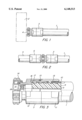
- FIGS. 1 and 2 are side elevational views of two different junctions of an HF cable.
- FIG. 3 is a side elevational view in partial cross section of a connecting element installed according to the invention.
- FIG. 1 illustrates an HF cable 1 which is connected to an electrical device 2.
- the HF cable 1 may be a coaxial cable of any type or also a hollow conductor.
- the end of the HF cable 1 has a connecting element 3 whereby it can be connected to a suitable connecting element 4 of the device 2.
- FIG. 2 illustrates the junction between two HF cables 1 and 5.
- the connecting element 3 is connected to a corresponding connecting element 6 which is attached to the HF cable 5.
- the connecting element 3 is attached to the end of a coaxial HF cable 1.
- the HF cable 1 in the illustrated embodiment has a corrugated tubular outer conductor 7, which concentrically surrounds an inner conductor 9 with a dielectric 8 between them.
- a sheath 10 made of an insulating material is placed over the outer conductor 7.
- the connecting element 3 is designed as a socket-shaped contact part.
- the contact part is composed of a tubular piece 11 and a connecting part 12, which can be screwed to the tubular piece 11 for example.
- a seal 13 can be placed between both parts.
- a rotatable clamping nut 14 can be installed at the free end of the connecting part 12.
- the contact part surrounds the end of the HF cable 1.
- a sealing material 15 is installed in the space between both parts.
- a good electrical connection to the outer conductor 1 is provided by a peripheral ring 16 of the connecting part 12, which is pressed against the tubular piece 11 by the threaded connection, and against the outer conductor 7 by a resilient tubular pressure element 17.
- the connecting element 3 is installed as follows:
- a predetermined length of the sheath 10 is removed from the outer conductor 7 at the end of the HF cable 1. Then, as illustrated in FIG. 3, the sealing material 15 is installed in the transition area between the outer conductor 7 and the sheath 10 so that it lies without axial interruption at least on a short axial path around the outer conductor 7 and the sheath 10 as well. After that the tubular piece 11 of the contact part with the inserted pressure element 17 is pushed over the end of the HF cable 1, and the connecting part 12 is screwed to it. The ring 16 and the pressure element 17 are thereby pressed against the outer conductor 7 on different sides. The contact part is installed in this way. The sealing material 15 is now able to enlarge its volume.
- the sealing material 15 contains at least two components which lead to an enlargement of its volume after the initialization.
- Suitable base materials are for example polyurethane and methylmethacrylate (MMA), which enlarge their volume through the addition of well-known reaction components.
- the base materials and the reaction components as well must be selected or adjusted so that a permanently elastic sealing material 15 results.
- the two components can be mixed shortly before they are applied in the described manner to the HF cable 1, for example, in a way so that the reaction for the volume enlargement starts after 10 minutes. The installer then has enough time to install the contact part without rushing.
- the sealing material 15 fills the space to the HF cable 1 which is surrounded by the tubular piece 11. It then seals the outer conductor 7, the sheath 10 and the tubular piece 11. No moisture can now penetrate into the connecting element 3 in this essentially critical area. The contact area between the contact part and the outer conductor 7 is effectively protected against moisture.
- the sealing material 15 can also be applied so that the entire space between the HF cable 1 and the contact part is filled axially along its full length.
- the contact part can also be made in one piece with the outer conductor 7.
- the outer conductor 7 can also be a smooth tube.
- the components of the sealing material 15 can first be stored in a premanufactured component, for example in a ring which is deformed during the installation of the connecting element 3 so that the components are united. The enlargement of the sealing material 15 volume can then start again after a corresponding delay. With this variation, it is possible to apply one of the components in microcapsules which are broken during the installation of the connecting element 3.
- the connecting element 3 is mounted on a coaxial HF cable 1.
- the connecting part 12 has a central insert 18 which protrudes into the inner conductor 9 and is insulated from the connecting part 12 by a peripheral insulator 19.
- the contact part with the tubular piece 11 and the connecting part 12 could also be used as a connecting element for hollow conductors.
Abstract
Description
Claims (10)
Applications Claiming Priority (2)
| Application Number | Priority Date | Filing Date | Title |
|---|---|---|---|
| DE19654012 | 1996-12-21 | ||
| DE19654012A DE19654012C2 (en) | 1996-12-21 | 1996-12-21 | Method for moisture-proof attachment of a connecting element to a high-frequency cable |
Publications (1)
| Publication Number | Publication Date |
|---|---|
| US6148513A true US6148513A (en) | 2000-11-21 |
Family
ID=7816008
Family Applications (1)
| Application Number | Title | Priority Date | Filing Date |
|---|---|---|---|
| US08/994,857 Expired - Fee Related US6148513A (en) | 1996-12-21 | 1997-12-19 | Method of applying a connecting element to a high-frequency cable in a moisture-proof manner |
Country Status (9)
| Country | Link |
|---|---|
| US (1) | US6148513A (en) |
| EP (1) | EP0849838B1 (en) |
| JP (1) | JPH10223305A (en) |
| KR (1) | KR19980064445A (en) |
| CN (1) | CN1192599A (en) |
| AU (1) | AU730306B2 (en) |
| BR (1) | BR9706381A (en) |
| DE (2) | DE19654012C2 (en) |
| RU (1) | RU2144251C1 (en) |
Cited By (16)
| Publication number | Priority date | Publication date | Assignee | Title |
|---|---|---|---|---|
| US6607398B2 (en) | 2000-04-17 | 2003-08-19 | Corning Gilbert Incorporated | Connector for a coaxial cable with corrugated outer conductor |
| EP1376773A2 (en) * | 2002-06-22 | 2004-01-02 | Spinner GmbH Elektrotechnische Fabrik | Coaxial Connector |
| US6955562B1 (en) | 2004-06-15 | 2005-10-18 | Corning Gilbert Inc. | Coaxial connector with center conductor seizure |
| US20060134979A1 (en) * | 2004-12-20 | 2006-06-22 | Henningsen Jimmy C | Coaxial connector with back nut clamping ring |
| US7261581B2 (en) | 2003-12-01 | 2007-08-28 | Corning Gilbert Inc. | Coaxial connector and method |
| US7448906B1 (en) | 2007-08-22 | 2008-11-11 | Andrew Llc | Hollow inner conductor contact for coaxial cable connector |
| US20090014212A1 (en) * | 2007-07-13 | 2009-01-15 | Malak Stephen P | Micro encapsulation seal for coaxial cable connectors and method of use thereof |
| US20090053931A1 (en) * | 2007-08-22 | 2009-02-26 | Andrew Llc | Sealed Inner Conductor Contact for Coaxial Cable Connector |
| US7632143B1 (en) | 2008-11-24 | 2009-12-15 | Andrew Llc | Connector with positive stop and compressible ring for coaxial cable and associated methods |
| US7635283B1 (en) | 2008-11-24 | 2009-12-22 | Andrew Llc | Connector with retaining ring for coaxial cable and associated methods |
| US20100126011A1 (en) * | 2008-11-24 | 2010-05-27 | Andrew, Llc, State/Country Of Incorporation: North Carolina | Flaring coaxial cable end preparation tool and associated methods |
| US20100130060A1 (en) * | 2008-11-24 | 2010-05-27 | Andrew, Llc | Connector including compressible ring for clamping a conductor of a coaxial cable and associated methods |
| US20100190377A1 (en) * | 2009-01-28 | 2010-07-29 | Andrew Llc, State/Country Of Incorporation: Delaware | Connector including flexible fingers and associated methods |
| US7785144B1 (en) | 2008-11-24 | 2010-08-31 | Andrew Llc | Connector with positive stop for coaxial cable and associated methods |
| US20130203287A1 (en) * | 2012-02-06 | 2013-08-08 | John Mezzalingua Associates, Inc. | Port assembly connector for engaging a coaxial cable and an outer conductor |
| CN110190576A (en) * | 2019-06-14 | 2019-08-30 | 深圳供电局有限公司 | The stern tube sealing of cable terminal |
Families Citing this family (1)
| Publication number | Priority date | Publication date | Assignee | Title |
|---|---|---|---|---|
| RU2645639C2 (en) * | 2016-04-21 | 2018-02-26 | Федеральное государственное бюджетное учреждение "Санкт-Петербургский многопрофильный центр" Министерства здравоохранения Российской Федерации | Method of ultrasound-assisted blockade in arthroscopic surgical interventions in the shoulder joint |
Citations (11)
| Publication number | Priority date | Publication date | Assignee | Title |
|---|---|---|---|---|
| US3678446A (en) * | 1970-06-02 | 1972-07-18 | Atomic Energy Commission | Coaxial cable connector |
| US3818120A (en) * | 1972-03-09 | 1974-06-18 | G Spinner | Coaxial plug connector |
| DE1943885C3 (en) * | 1969-08-29 | 1979-01-18 | Kabel- Und Metallwerke Gutehoffnungshuette Ag, 3000 Hannover | Connection element for two electromagnetic waveguides |
| US5002475A (en) * | 1988-10-04 | 1991-03-26 | Intellex Corporation | Reaction injection molding apparatus |
| EP0432662A1 (en) * | 1989-12-13 | 1991-06-19 | King Technology Of Missouri, Inc. | Waterproof wire connectors |
| US5137470A (en) * | 1991-06-04 | 1992-08-11 | Andrew Corporation | Connector for coaxial cable having a helically corrugated inner conductor |
| US5167533A (en) * | 1992-01-08 | 1992-12-01 | Andrew Corporation | Connector for coaxial cable having hollow inner conductors |
| DE4439366A1 (en) * | 1993-11-04 | 1995-05-11 | Yazaki Corp | Watertight sealing composition for connection elements |
| FR2718574A1 (en) * | 1994-04-12 | 1995-10-13 | Vagnone Boeri Srl | Method of sealing an electrical connector and connector thus obtained. |
| US5766037A (en) * | 1996-10-11 | 1998-06-16 | Radio Frequency Systems, Inc. | Connector for a radio frequency cable |
| US5859132A (en) * | 1996-04-01 | 1999-01-12 | The Goodyear Tire & Rubber Company | Composition having low compression set |
Family Cites Families (1)
| Publication number | Priority date | Publication date | Assignee | Title |
|---|---|---|---|---|
| DE1968186U (en) * | 1967-07-11 | 1967-09-14 | Felten & Guilleaume Carlswerk | SEAL BETWEEN THE FLANGE AND A HIGH FREQUENCY CABLE OR A HOLLOW ELECTRIC CONDUCTOR. |
-
1996
- 1996-12-21 DE DE19654012A patent/DE19654012C2/en not_active Expired - Fee Related
-
1997
- 1997-11-25 EP EP97402822A patent/EP0849838B1/en not_active Expired - Lifetime
- 1997-11-25 DE DE59707323T patent/DE59707323D1/en not_active Expired - Fee Related
- 1997-12-15 AU AU48392/97A patent/AU730306B2/en not_active Ceased
- 1997-12-17 BR BR9706381A patent/BR9706381A/en not_active IP Right Cessation
- 1997-12-19 JP JP9351395A patent/JPH10223305A/en active Pending
- 1997-12-19 CN CN97108742A patent/CN1192599A/en active Pending
- 1997-12-19 RU RU97122266A patent/RU2144251C1/en active
- 1997-12-19 US US08/994,857 patent/US6148513A/en not_active Expired - Fee Related
- 1997-12-20 KR KR1019970071337A patent/KR19980064445A/en not_active Application Discontinuation
Patent Citations (11)
| Publication number | Priority date | Publication date | Assignee | Title |
|---|---|---|---|---|
| DE1943885C3 (en) * | 1969-08-29 | 1979-01-18 | Kabel- Und Metallwerke Gutehoffnungshuette Ag, 3000 Hannover | Connection element for two electromagnetic waveguides |
| US3678446A (en) * | 1970-06-02 | 1972-07-18 | Atomic Energy Commission | Coaxial cable connector |
| US3818120A (en) * | 1972-03-09 | 1974-06-18 | G Spinner | Coaxial plug connector |
| US5002475A (en) * | 1988-10-04 | 1991-03-26 | Intellex Corporation | Reaction injection molding apparatus |
| EP0432662A1 (en) * | 1989-12-13 | 1991-06-19 | King Technology Of Missouri, Inc. | Waterproof wire connectors |
| US5137470A (en) * | 1991-06-04 | 1992-08-11 | Andrew Corporation | Connector for coaxial cable having a helically corrugated inner conductor |
| US5167533A (en) * | 1992-01-08 | 1992-12-01 | Andrew Corporation | Connector for coaxial cable having hollow inner conductors |
| DE4439366A1 (en) * | 1993-11-04 | 1995-05-11 | Yazaki Corp | Watertight sealing composition for connection elements |
| FR2718574A1 (en) * | 1994-04-12 | 1995-10-13 | Vagnone Boeri Srl | Method of sealing an electrical connector and connector thus obtained. |
| US5859132A (en) * | 1996-04-01 | 1999-01-12 | The Goodyear Tire & Rubber Company | Composition having low compression set |
| US5766037A (en) * | 1996-10-11 | 1998-06-16 | Radio Frequency Systems, Inc. | Connector for a radio frequency cable |
Cited By (31)
| Publication number | Priority date | Publication date | Assignee | Title |
|---|---|---|---|---|
| US6607398B2 (en) | 2000-04-17 | 2003-08-19 | Corning Gilbert Incorporated | Connector for a coaxial cable with corrugated outer conductor |
| EP1376773A2 (en) * | 2002-06-22 | 2004-01-02 | Spinner GmbH Elektrotechnische Fabrik | Coaxial Connector |
| EP1376773A3 (en) * | 2002-06-22 | 2004-07-28 | Spinner GmbH Elektrotechnische Fabrik | Coaxial Connector |
| US6976872B1 (en) | 2002-06-22 | 2005-12-20 | Spinner Gmbh | Coaxial connector |
| US7261581B2 (en) | 2003-12-01 | 2007-08-28 | Corning Gilbert Inc. | Coaxial connector and method |
| US6955562B1 (en) | 2004-06-15 | 2005-10-18 | Corning Gilbert Inc. | Coaxial connector with center conductor seizure |
| US7104839B2 (en) | 2004-06-15 | 2006-09-12 | Corning Gilbert Inc. | Coaxial connector with center conductor seizure |
| US20060040552A1 (en) * | 2004-06-15 | 2006-02-23 | Henningsen Jimmy C | Coaxial connector with center conductor seizure |
| US20060134979A1 (en) * | 2004-12-20 | 2006-06-22 | Henningsen Jimmy C | Coaxial connector with back nut clamping ring |
| US7077700B2 (en) | 2004-12-20 | 2006-07-18 | Corning Gilbert Inc. | Coaxial connector with back nut clamping ring |
| US8137133B2 (en) | 2007-07-13 | 2012-03-20 | John Mezzalingua Associates, Inc. | Micro encapsulation seal for coaxial cable connectors and method of use thereof |
| US20090014212A1 (en) * | 2007-07-13 | 2009-01-15 | Malak Stephen P | Micro encapsulation seal for coaxial cable connectors and method of use thereof |
| US20110124222A1 (en) * | 2007-07-13 | 2011-05-26 | Malak Stephen P | Micro encapsulation seal for coaxial cable connectors and method of use thereof |
| US20090258537A1 (en) * | 2007-07-13 | 2009-10-15 | Malak Stephen P | Microencapsulation seal for coaxial cable connectors and method of use thereof |
| US7828596B2 (en) | 2007-07-13 | 2010-11-09 | John Mezzalingua Assoc., Inc. | Microencapsulation seal for coaxial cable connectors and method of use thereof |
| US7819698B2 (en) | 2007-08-22 | 2010-10-26 | Andrew Llc | Sealed inner conductor contact for coaxial cable connector |
| US20090053931A1 (en) * | 2007-08-22 | 2009-02-26 | Andrew Llc | Sealed Inner Conductor Contact for Coaxial Cable Connector |
| US7448906B1 (en) | 2007-08-22 | 2008-11-11 | Andrew Llc | Hollow inner conductor contact for coaxial cable connector |
| US7632143B1 (en) | 2008-11-24 | 2009-12-15 | Andrew Llc | Connector with positive stop and compressible ring for coaxial cable and associated methods |
| US7785144B1 (en) | 2008-11-24 | 2010-08-31 | Andrew Llc | Connector with positive stop for coaxial cable and associated methods |
| US7635283B1 (en) | 2008-11-24 | 2009-12-22 | Andrew Llc | Connector with retaining ring for coaxial cable and associated methods |
| US20100126011A1 (en) * | 2008-11-24 | 2010-05-27 | Andrew, Llc, State/Country Of Incorporation: North Carolina | Flaring coaxial cable end preparation tool and associated methods |
| US7731529B1 (en) | 2008-11-24 | 2010-06-08 | Andrew Llc | Connector including compressible ring for clamping a conductor of a coaxial cable and associated methods |
| US20100130060A1 (en) * | 2008-11-24 | 2010-05-27 | Andrew, Llc | Connector including compressible ring for clamping a conductor of a coaxial cable and associated methods |
| US8136234B2 (en) | 2008-11-24 | 2012-03-20 | Andrew Llc | Flaring coaxial cable end preparation tool and associated methods |
| US20100190377A1 (en) * | 2009-01-28 | 2010-07-29 | Andrew Llc, State/Country Of Incorporation: Delaware | Connector including flexible fingers and associated methods |
| US7931499B2 (en) | 2009-01-28 | 2011-04-26 | Andrew Llc | Connector including flexible fingers and associated methods |
| US20130203287A1 (en) * | 2012-02-06 | 2013-08-08 | John Mezzalingua Associates, Inc. | Port assembly connector for engaging a coaxial cable and an outer conductor |
| US9017102B2 (en) * | 2012-02-06 | 2015-04-28 | John Mezzalingua Associates, LLC | Port assembly connector for engaging a coaxial cable and an outer conductor |
| CN110190576A (en) * | 2019-06-14 | 2019-08-30 | 深圳供电局有限公司 | The stern tube sealing of cable terminal |
| CN110190576B (en) * | 2019-06-14 | 2021-02-05 | 深圳供电局有限公司 | Tail pipe sealing device of cable terminal |
Also Published As
| Publication number | Publication date |
|---|---|
| DE59707323D1 (en) | 2002-06-27 |
| KR19980064445A (en) | 1998-10-07 |
| DE19654012A1 (en) | 1998-07-02 |
| AU4839297A (en) | 1998-06-25 |
| DE19654012C2 (en) | 1999-08-12 |
| EP0849838A2 (en) | 1998-06-24 |
| JPH10223305A (en) | 1998-08-21 |
| EP0849838A3 (en) | 1999-08-18 |
| EP0849838B1 (en) | 2002-05-22 |
| CN1192599A (en) | 1998-09-09 |
| AU730306B2 (en) | 2001-03-01 |
| BR9706381A (en) | 1999-03-02 |
| RU2144251C1 (en) | 2000-01-10 |
Similar Documents
| Publication | Publication Date | Title |
|---|---|---|
| US6148513A (en) | Method of applying a connecting element to a high-frequency cable in a moisture-proof manner | |
| US6331123B1 (en) | Connector for hard-line coaxial cable | |
| US3406373A (en) | Coaxial connector assembly | |
| AU603731B2 (en) | Method for terminating a conductive polymer shielded coaxial electrical cable | |
| US4110550A (en) | Electrical connector with adaptor for paper-insulated, lead-jacketed electrical cables and method | |
| US5648639A (en) | Glands for terminating cables and pipes | |
| US4079189A (en) | High voltage cable splice | |
| US5496968A (en) | Shielded cable connecting terminal | |
| US5052946A (en) | Plug connector for high-voltage coaxial cables | |
| AU2009212879B2 (en) | Apparatus for a Connection Point between Two Electrical High Voltage Cables | |
| US4493522A (en) | Sealed cable connector | |
| US4234755A (en) | Adaptor for paper-insulated, lead-jacketed electrical cables | |
| KR20120016258A (en) | Cold-shrink separable connector | |
| US4238639A (en) | Joint for low and medium voltage electric cables | |
| US6638107B1 (en) | Cable coupling device | |
| US4839470A (en) | Underwater (submersible) joint or splice | |
| US3377422A (en) | Splice assembly to connect cable ends together | |
| US3343122A (en) | Junction device for electric cable of the coaxial type, more particularly for high-tension coaxial cable | |
| JP2003223943A (en) | Coupling sleeve for inorganic insulation cable and connecting method | |
| EP1253692A1 (en) | Terminal of a medium voltage electrical cable | |
| US5989058A (en) | Electrical wire/cable connector | |
| US6948955B2 (en) | Terminal of a medium voltage electrical cable | |
| US2827508A (en) | Terminal assembly for shielded cables | |
| US3335215A (en) | Stress relief apparatus | |
| US3347977A (en) | Homogeneous sodium conductor connections |
Legal Events
| Date | Code | Title | Description |
|---|---|---|---|
| AS | Assignment |
Owner name: ALCATEL ALSTHOM COMPAGNIE GENERALE D'ELECTRICITE, Free format text: ASSIGNMENT OF ASSIGNORS INTEREST;ASSIGNORS:SCHIEFER, JURGEN;HORN, THOMAS;STANSBIE, MICHAEL;REEL/FRAME:009042/0783;SIGNING DATES FROM 19980220 TO 19980225 |
|
| AS | Assignment |
Owner name: ALCATEL, FRANCE Free format text: CHANGE OF NAME;ASSIGNOR:ALCATEL ALSTHOM COMPAGNIE GENERALE D'ELECTRICITE;REEL/FRAME:010070/0287 Effective date: 19980914 |
|
| FEPP | Fee payment procedure |
Free format text: PAYOR NUMBER ASSIGNED (ORIGINAL EVENT CODE: ASPN); ENTITY STATUS OF PATENT OWNER: LARGE ENTITY |
|
| REMI | Maintenance fee reminder mailed | ||
| LAPS | Lapse for failure to pay maintenance fees | ||
| STCH | Information on status: patent discontinuation |
Free format text: PATENT EXPIRED DUE TO NONPAYMENT OF MAINTENANCE FEES UNDER 37 CFR 1.362 |
|
| FP | Lapsed due to failure to pay maintenance fee |
Effective date: 20041121 |