US6147420A - Wireless switching system - Google Patents
Wireless switching system Download PDFInfo
- Publication number
- US6147420A US6147420A US09/125,369 US12536998A US6147420A US 6147420 A US6147420 A US 6147420A US 12536998 A US12536998 A US 12536998A US 6147420 A US6147420 A US 6147420A
- Authority
- US
- United States
- Prior art keywords
- resonant
- resonant circuit
- circuit
- frequency
- field
- Prior art date
- Legal status (The legal status is an assumption and is not a legal conclusion. Google has not performed a legal analysis and makes no representation as to the accuracy of the status listed.)
- Expired - Lifetime
Links
Images
Classifications
-
- G—PHYSICS
- G06—COMPUTING; CALCULATING OR COUNTING
- G06K—GRAPHICAL DATA READING; PRESENTATION OF DATA; RECORD CARRIERS; HANDLING RECORD CARRIERS
- G06K13/00—Conveying record carriers from one station to another, e.g. from stack to punching mechanism
- G06K13/02—Conveying record carriers from one station to another, e.g. from stack to punching mechanism the record carrier having longitudinal dimension comparable with transverse dimension, e.g. punched card
- G06K13/08—Feeding or discharging cards
- G06K13/0806—Feeding or discharging cards using an arrangement for ejection of an inserted card
- G06K13/0825—Feeding or discharging cards using an arrangement for ejection of an inserted card the ejection arrangement being of the push-push kind
-
- G—PHYSICS
- G07—CHECKING-DEVICES
- G07C—TIME OR ATTENDANCE REGISTERS; REGISTERING OR INDICATING THE WORKING OF MACHINES; GENERATING RANDOM NUMBERS; VOTING OR LOTTERY APPARATUS; ARRANGEMENTS, SYSTEMS OR APPARATUS FOR CHECKING NOT PROVIDED FOR ELSEWHERE
- G07C9/00—Individual registration on entry or exit
- G07C9/00174—Electronically operated locks; Circuits therefor; Nonmechanical keys therefor, e.g. passive or active electrical keys or other data carriers without mechanical keys
- G07C9/00182—Electronically operated locks; Circuits therefor; Nonmechanical keys therefor, e.g. passive or active electrical keys or other data carriers without mechanical keys operated with unidirectional data transmission between data carrier and locks
-
- G—PHYSICS
- G07—CHECKING-DEVICES
- G07C—TIME OR ATTENDANCE REGISTERS; REGISTERING OR INDICATING THE WORKING OF MACHINES; GENERATING RANDOM NUMBERS; VOTING OR LOTTERY APPARATUS; ARRANGEMENTS, SYSTEMS OR APPARATUS FOR CHECKING NOT PROVIDED FOR ELSEWHERE
- G07C9/00—Individual registration on entry or exit
- G07C9/00174—Electronically operated locks; Circuits therefor; Nonmechanical keys therefor, e.g. passive or active electrical keys or other data carriers without mechanical keys
- G07C2009/00753—Electronically operated locks; Circuits therefor; Nonmechanical keys therefor, e.g. passive or active electrical keys or other data carriers without mechanical keys operated by active electrical keys
- G07C2009/00769—Electronically operated locks; Circuits therefor; Nonmechanical keys therefor, e.g. passive or active electrical keys or other data carriers without mechanical keys operated by active electrical keys with data transmission performed by wireless means
- G07C2009/00793—Electronically operated locks; Circuits therefor; Nonmechanical keys therefor, e.g. passive or active electrical keys or other data carriers without mechanical keys operated by active electrical keys with data transmission performed by wireless means by Hertzian waves
Definitions
- the present invention relates generally to a system for providing remote wireless switches.
- Switches are mounted in various locations inside the vehicle, including in the doors and on the steering wheel.
- the wiring required by these numerous switches increases the time for assembly and the cost of the vehicle.
- Each connection between wires provides a potential failure point in the system.
- the wiring for these numerous switches increases the total weight of the vehicle.
- RF transmitters such as are used for remote entry systems can be used as a wireless switch; however, the RF transmitter requires a power supply, such as a battery, which must be replaced periodically.
- the present invention provides a wireless switching system.
- the wireless switching system includes a central transmitter unit which generates a plurality of electromagnetic frequencies.
- a plurality of user-activated switches each selectively open and close a resonant circuit within the electromagnetic field generated by the central transmitter unit.
- Each of the resonant circuits has a unique resonant frequency which is included in the plurality of frequencies generated by the central transmitter unit.
- the central transmitter unit continuously generates the electromagnetic field. When one of the switches is closed, the associated resonant circuit consumes energy at its resonant frequency from the electromagnetic field generated by the central transmitter unit.
- the central transmitter unit continuously monitors its energy consumption and the frequencies at which energy is consumed. When the central transmitter unit detects energy consumption at one of the resonant frequencies, it activates the vehicle function associated with the switch that closed the resonant circuit.
- the wireless switching can also be used as a passive anti-theft device.
- the driver carries a card having a resonant circuit having a resonant frequency.
- the central transmitter unit detects the presence of the resonant circuit and releases the use of the car.
- a plurality of resonant circuits can be multiplexed in order to accommodate a higher number of vehicle functions. For example, each of a plurality of user switches in a door of a vehicle could be assigned to a unique combination of two or three of the resonant circuits.
- the resonant circuit is inexpensive and simple and can be made by metal stamping, printing or by vacuum evaporation and can be contained inside the switches.
- the wireless switching system eliminates the need to wire each switch to a controller. Reduction of wiring in a vehicle decreases the vehicle assembly time, cost and weight. Further, the resonant circuits require no power supply to be recharged or replaced periodically.
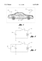
- FIG. 1 is a schematic of the present invention as installed in a vehicle.
- FIG. 2 is a schematic of one possible resonant circuit that can be used in the wireless switching system of FIG. 1.
- FIG. 3 is a schematic of an alternate resonant circuit which can be used in the wireless switching system of FIG. 1.
- the present invention provides a wireless switching system 20 generally comprising a central transmitter unit 22 generating an electromagnetic field having a plurality of frequencies in a vehicle 23.
- a plurality of resonant circuits 24 are selectively opened and closed by user-activated switches 26. When its associated switch 26 is closed, each resonant circuit 24 has a unique resonant frequency which is included in the plurality of frequencies generated by the central transmitter unit 22.
- the resonant circuits 24 and switches 26 are located throughout the interior of the vehicle 23, such as in the doors or on the steering wheel.
- the driver of the vehicle 23 carries a driver identification card 30 which includes a closed resonant circuit 32 having a unique resonant frequency.
- the driver identification card 30 need not include a user-activated switch.
- the central transmitter unit 22 continuously monitors its power consumption and the frequencies at which the power is consumed.
- the central transmitter unit 22 generates a single electromagnetic signal which includes all of the resonant frequencies of the resonant circuits 24, and by using Fourier analysis determines the frequencies at which power is consumed.
- the central transmitter unit 22 comprises a plurality of frequency generating circuits which each generate an electromagnetic field at one of the resonant frequencies of the resonant circuits 24. Given this detailed description of the present invention, the details of the central transmitter unit 22 are within the skill of one skilled in the art of electromagnetic field generators and circuits for monitoring power consumption.
- the central transmitter unit 22 In operation, the central transmitter unit 22 generates the resonant frequencies of the resonant circuits 24 and 32. If all of these switches 26 are open and the driver identification card 30 is not within the electromagnetic field generated by the central transmitter unit 22, the central transmitter unit 22 determines that no power (or insufficient power) has been consumed at any of the resonant frequencies. Upon activation of a switch 26, the associated resonant circuit 24 is closed and begins to consume power at its resonant frequency. The central transmitter unit 22 detects that energy is being consumed at the resonant frequency and activates a vehicle function circuit 34 associated with the user activated switch 26.
- the central transmitter unit 22 determines that the driver identification card 30 is not present within the electromagnetic field, the central transmitter unit 22 prevents the release of the vehicle 23, such as by locking the doors or otherwise disabling the vehicle 23.
- the resonant circuit 32 absorbs energy at its resonant frequency. This energy consumption is detected by the central transmitter unit 22, which then releases the use of the vehicle 23.
- FIG. 2 is a schematic of a resonant circuit 24 which could be used in the wireless switching system 20 of FIG. 1.
- the associated user-activated switch 26 selectively opens and closes the resonant circuit 24 which comprises a capacitor 36 and an inductor 38.
- Some part of the resonant circuit 24 acts as an antenna at the resonant frequency to receive the energy from the electromagnetic field.
- the shape, size, manufacture and implementation of the antenna into the present invention are well within the skill of the art.
- FIG. 3 is a schematic of an alternate resonant circuit 44 which could be used in the wireless switching system 20 of FIG. 1.
- the alternate resonant circuit 44 includes the user activated switch 26 which selectively opens and closes a circuit comprising a capacitor, an inductor, and a resistor 46. Addition of the resistor 46 to the resonant circuit 44 increases the time over which the energy at the resonant frequency is consumed, thereby making possible push-push functions in an extended time frame.
- the wireless switching system 20 has been described as installed in a vehicle 23 only for purpose of illustration. It should be recognized that the wireless switching system 20 has many other applications, including switches in elevator cabins. Further, the user activated switches 26, each having an associated vehicle function, could each activate a combination of resonant circuits 24 of different resonant frequencies, such that energy loss at this combination of frequencies is required in order to activate the vehicle function. Further, for a plurality of user activated switches 26 mounted generally in a single location, a plurality of resonant circuits 24 each having a unique resonant frequency could be multiplexed, i.e. each user activated switch 26 would close a different combination of the plurality of resonant circuits 24, thereby reducing the number of resonant circuits 24 required for a given number of vehicle functions.
Abstract
Description
Claims (10)
Priority Applications (1)
| Application Number | Priority Date | Filing Date | Title |
|---|---|---|---|
| US09/125,369 US6147420A (en) | 1997-12-16 | 1997-12-16 | Wireless switching system |
Applications Claiming Priority (2)
| Application Number | Priority Date | Filing Date | Title |
|---|---|---|---|
| US09/125,369 US6147420A (en) | 1997-12-16 | 1997-12-16 | Wireless switching system |
| PCT/US1997/022673 WO1998027522A1 (en) | 1996-12-17 | 1997-12-16 | Wireless switching system |
Publications (1)
| Publication Number | Publication Date |
|---|---|
| US6147420A true US6147420A (en) | 2000-11-14 |
Family
ID=22419420
Family Applications (1)
| Application Number | Title | Priority Date | Filing Date |
|---|---|---|---|
| US09/125,369 Expired - Lifetime US6147420A (en) | 1997-12-16 | 1997-12-16 | Wireless switching system |
Country Status (1)
| Country | Link |
|---|---|
| US (1) | US6147420A (en) |
Cited By (6)
| Publication number | Priority date | Publication date | Assignee | Title |
|---|---|---|---|---|
| FR2818841A1 (en) * | 2000-12-22 | 2002-06-28 | Giat Ind Sa | FREQUENTIAL MULTIPLEXER |
| WO2002068781A1 (en) * | 2001-02-24 | 2002-09-06 | Saint-Gobain Glass France | Device for actuating a lock |
| US6700310B2 (en) | 2000-10-13 | 2004-03-02 | Lear Corporation | Self-powered wireless switch |
| US6933655B2 (en) | 2000-10-13 | 2005-08-23 | Lear Corporation | Self-powered wireless switch |
| US20070139216A1 (en) * | 2000-09-08 | 2007-06-21 | Automotive Technologies International, Inc. | Vehicular Component Control Using Wireless Switch Assemblies |
| EP3041012A1 (en) * | 2014-12-29 | 2016-07-06 | Eaton Corporation | Self-identifying control switch |
Citations (15)
| Publication number | Priority date | Publication date | Assignee | Title |
|---|---|---|---|---|
| US3299424A (en) * | 1965-05-07 | 1967-01-17 | Jorgen P Vinding | Interrogator-responder identification system |
| US3609741A (en) * | 1969-03-21 | 1971-09-28 | Wendell S Miller | Prevention of unauthorized movement of articles between predetermined areas |
| US3696379A (en) * | 1970-12-02 | 1972-10-03 | Knogo Corp | Apparatus for article theft detection |
| US4196418A (en) * | 1976-11-01 | 1980-04-01 | N.V. Nederlandsche Apparatenfabriek Nedap | Detection plate for an identification system |
| US4523178A (en) * | 1982-02-22 | 1985-06-11 | Fulhorst George E | Wireless alarm system in conjunction with at least one vehicle |
| US4551654A (en) * | 1981-06-05 | 1985-11-05 | Kesser Electronics International, Inc. | Lighting control system and method |
| US4893118A (en) * | 1986-11-25 | 1990-01-09 | Societe Fontaine | Device for identification by proximity |
| EP0380314A1 (en) * | 1989-01-23 | 1990-08-01 | Omron Corporation | Wireless switch |
| US4973912A (en) * | 1988-04-15 | 1990-11-27 | Daimler-Benz Aktiengesellschaft | Method for contactless measurement of a resistance arranged in the secondary circuit of a transformer and device for carrying out the method |
| US5053774A (en) * | 1987-07-31 | 1991-10-01 | Texas Instruments Deutschland Gmbh | Transponder arrangement |
| US5457461A (en) * | 1993-08-11 | 1995-10-10 | Texas Instruments Deutschland Gmbh | Method and arrangement for detecting adjacent transponders |
| US5497311A (en) * | 1994-03-22 | 1996-03-05 | Yokogawa Electric Corporation | Switching power source of the voltage resonance type |
| US5552789A (en) * | 1994-02-14 | 1996-09-03 | Texas Instruments Deutschland Gmbh | Integrated vehicle communications system |
| US5606314A (en) * | 1990-11-14 | 1997-02-25 | Canon Kabushiki Kaisha | Information processing system connected by radio communication |
| US5616966A (en) * | 1994-11-07 | 1997-04-01 | Siemens Aktiengesellschaft | Anti-theft system for a motor vehicle |
-
1997
- 1997-12-16 US US09/125,369 patent/US6147420A/en not_active Expired - Lifetime
Patent Citations (15)
| Publication number | Priority date | Publication date | Assignee | Title |
|---|---|---|---|---|
| US3299424A (en) * | 1965-05-07 | 1967-01-17 | Jorgen P Vinding | Interrogator-responder identification system |
| US3609741A (en) * | 1969-03-21 | 1971-09-28 | Wendell S Miller | Prevention of unauthorized movement of articles between predetermined areas |
| US3696379A (en) * | 1970-12-02 | 1972-10-03 | Knogo Corp | Apparatus for article theft detection |
| US4196418A (en) * | 1976-11-01 | 1980-04-01 | N.V. Nederlandsche Apparatenfabriek Nedap | Detection plate for an identification system |
| US4551654A (en) * | 1981-06-05 | 1985-11-05 | Kesser Electronics International, Inc. | Lighting control system and method |
| US4523178A (en) * | 1982-02-22 | 1985-06-11 | Fulhorst George E | Wireless alarm system in conjunction with at least one vehicle |
| US4893118A (en) * | 1986-11-25 | 1990-01-09 | Societe Fontaine | Device for identification by proximity |
| US5053774A (en) * | 1987-07-31 | 1991-10-01 | Texas Instruments Deutschland Gmbh | Transponder arrangement |
| US4973912A (en) * | 1988-04-15 | 1990-11-27 | Daimler-Benz Aktiengesellschaft | Method for contactless measurement of a resistance arranged in the secondary circuit of a transformer and device for carrying out the method |
| EP0380314A1 (en) * | 1989-01-23 | 1990-08-01 | Omron Corporation | Wireless switch |
| US5606314A (en) * | 1990-11-14 | 1997-02-25 | Canon Kabushiki Kaisha | Information processing system connected by radio communication |
| US5457461A (en) * | 1993-08-11 | 1995-10-10 | Texas Instruments Deutschland Gmbh | Method and arrangement for detecting adjacent transponders |
| US5552789A (en) * | 1994-02-14 | 1996-09-03 | Texas Instruments Deutschland Gmbh | Integrated vehicle communications system |
| US5497311A (en) * | 1994-03-22 | 1996-03-05 | Yokogawa Electric Corporation | Switching power source of the voltage resonance type |
| US5616966A (en) * | 1994-11-07 | 1997-04-01 | Siemens Aktiengesellschaft | Anti-theft system for a motor vehicle |
Cited By (10)
| Publication number | Priority date | Publication date | Assignee | Title |
|---|---|---|---|---|
| US20070139216A1 (en) * | 2000-09-08 | 2007-06-21 | Automotive Technologies International, Inc. | Vehicular Component Control Using Wireless Switch Assemblies |
| US7889096B2 (en) | 2000-09-08 | 2011-02-15 | Automotive Technologies International, Inc. | Vehicular component control using wireless switch assemblies |
| US6700310B2 (en) | 2000-10-13 | 2004-03-02 | Lear Corporation | Self-powered wireless switch |
| US6933655B2 (en) | 2000-10-13 | 2005-08-23 | Lear Corporation | Self-powered wireless switch |
| FR2818841A1 (en) * | 2000-12-22 | 2002-06-28 | Giat Ind Sa | FREQUENTIAL MULTIPLEXER |
| WO2002052520A1 (en) * | 2000-12-22 | 2002-07-04 | Giat Industries | Frequency multiplexer |
| WO2002068781A1 (en) * | 2001-02-24 | 2002-09-06 | Saint-Gobain Glass France | Device for actuating a lock |
| US20040113491A1 (en) * | 2001-02-24 | 2004-06-17 | Helmut Mauser | Actuation device for actuating a lock |
| EP3041012A1 (en) * | 2014-12-29 | 2016-07-06 | Eaton Corporation | Self-identifying control switch |
| US9619680B2 (en) | 2014-12-29 | 2017-04-11 | Eaton Corporation | Self-identifying control switch |
Similar Documents
| Publication | Publication Date | Title |
|---|---|---|
| US6025783A (en) | Wireless switch detection system | |
| US9789830B2 (en) | Energy supply circuit for electric components | |
| CN1119488C (en) | Locking system, particularly for motor vehicle | |
| US7098791B2 (en) | Security system and portable device usable therein | |
| US6011321A (en) | Page receiver security system | |
| US6056076A (en) | Control system for an automotive vehicle having at least one electrically operated door lock | |
| JP3789335B2 (en) | Keyless entry device that also functions as a tire pressure monitor | |
| CN101136114A (en) | Keyless passive entry system | |
| US10385594B2 (en) | Power locking door handle with capacitive sensing | |
| CA2415011C (en) | Vehicle data communications bus disrupter and associated methods | |
| US9600947B2 (en) | Lock system, in particular for a motor vehicle | |
| JP4140731B2 (en) | Vehicle communication device | |
| CN101385049B (en) | Switching device | |
| US5023468A (en) | Safety device for car passengers | |
| US6147420A (en) | Wireless switching system | |
| JP6170436B2 (en) | Electronic communication module for locking / unlocking movable panels of automobiles, associated central processing unit for control, and hands-free access system | |
| US7501937B2 (en) | Vehicle security device including pre-warn indicator and related methods | |
| US20100039222A1 (en) | Keyless access system and method for a truck and truck equipped with such a system | |
| WO1998027522A1 (en) | Wireless switching system | |
| JP2004092062A (en) | Locking/unlocking control device for vehicle | |
| JP2005178635A (en) | Vehicle controller | |
| US20030011471A1 (en) | Motion sensing apparatus having a control module and a slave module | |
| CN107499153A (en) | A kind of electric automobile with maintenance active safety function | |
| KR20080036824A (en) | Method for unlock and lock the door of a passive keyless entry system for a vehicle | |
| US20040113491A1 (en) | Actuation device for actuating a lock |
Legal Events
| Date | Code | Title | Description |
|---|---|---|---|
| AS | Assignment |
Owner name: UNITED TECHNOLOGIES AUTOMOTIVE, INC., MICHIGAN Free format text: ASSIGNMENT OF ASSIGNORS INTEREST;ASSIGNOR:ROSER, HERMANN;REEL/FRAME:009497/0285 Effective date: 19971226 |
|
| AS | Assignment |
Owner name: UNITED TECHNOLOGIES AUTOMOTIVE, INC., MICHIGAN Free format text: ASSIGNMENT OF ASSIGNORS INTEREST;ASSIGNOR:ROSER, HERMANN;REEL/FRAME:009842/0336 Effective date: 19971226 |
|
| AS | Assignment |
Owner name: UT AUTOMOTIVE DEARBORN, INC., MICHIGAN Free format text: ASSIGNMENT OF ASSIGNORS INTEREST;ASSIGNOR:UNITED TECHNOLOGIES AUTOMOTIVE, INC.;REEL/FRAME:009478/0475 Effective date: 19980917 |
|
| AS | Assignment |
Owner name: LEAR AUTOMOTIVE DEARBORN, INC., MICHIGAN Free format text: CHANGE OF NAME;ASSIGNOR:UT AUTOMOTIVE DEARBORN, INC.;REEL/FRAME:010061/0393 Effective date: 19990528 |
|
| STCF | Information on status: patent grant |
Free format text: PATENTED CASE |
|
| FEPP | Fee payment procedure |
Free format text: PAYER NUMBER DE-ASSIGNED (ORIGINAL EVENT CODE: RMPN); ENTITY STATUS OF PATENT OWNER: LARGE ENTITY Free format text: PAYOR NUMBER ASSIGNED (ORIGINAL EVENT CODE: ASPN); ENTITY STATUS OF PATENT OWNER: LARGE ENTITY |
|
| FPAY | Fee payment |
Year of fee payment: 4 |
|
| AS | Assignment |
Owner name: JPMORGAN CHASE BANK, N.A., AS GENERAL ADMINISTRATI Free format text: SECURITY AGREEMENT;ASSIGNOR:LEAR AUTOMOTIVE DEARBORN, INC.;REEL/FRAME:017823/0950 Effective date: 20060425 |
|
| FPAY | Fee payment |
Year of fee payment: 8 |
|
| AS | Assignment |
Owner name: JPMORGAN CHASE BANK, N.A., AS ADMINISTRATIVE AGENT Free format text: GRANT OF FIRST LIEN SECURITY INTEREST IN PATENT RIGHTS;ASSIGNOR:LEAR AUTOMOTIVE DEARBORN, INC.;REEL/FRAME:023519/0683 Effective date: 20091109 Owner name: JPMORGAN CHASE BANK, N.A., AS ADMINISTRATIVE AGENT Free format text: GRANT OF SECOND LIEN SECURITY INTEREST IN PATENT RIGHTS;ASSIGNOR:LEAR AUTOMOTIVE DEARBORN, INC.;REEL/FRAME:023519/0699 Effective date: 20091109 |
|
| FPAY | Fee payment |
Year of fee payment: 12 |
|
| AS | Assignment |
Owner name: LEAR CORPORATION EEDS AND INTERIORS, MICHIGAN Free format text: MERGER;ASSIGNOR:LEAR AUTOMOTIVE DEARBORN, INC.;REEL/FRAME:029732/0846 Effective date: 20111115 |
|
| AS | Assignment |
Owner name: JPMORGAN CHASE BANK, N.A., AS AGENT, ILLINOIS Free format text: SECURITY AGREEMENT;ASSIGNOR:LEAR CORPORATION EEDS AND INTERIORS;REEL/FRAME:029923/0618 Effective date: 20130130 |
|
| AS | Assignment |
Owner name: LEAR AUTOMOTIVE DEARBORN, INC., MICHIGAN Free format text: RELEASE BY SECURED PARTY;ASSIGNOR:JPMORGAN CHASE BANK, N.A.;REEL/FRAME:032712/0676 Effective date: 20100830 Owner name: LEAR AUTOMOTIVE DEARBORN, INC., MICHIGAN Free format text: RELEASE BY SECURED PARTY;ASSIGNOR:JPMORGAN CHASE BANK, N.A.;REEL/FRAME:032712/0428 Effective date: 20100830 |
|
| AS | Assignment |
Owner name: LEAR CORPORATION EEDS AND INTERIORS, MICHIGAN Free format text: RELEASE BY SECURED PARTY;ASSIGNOR:JPMORGAN CHASE BANK, N.A., AS AGENT;REEL/FRAME:037701/0171 Effective date: 20160104 |