US6147017A - Industrial fibers with sinusoidal cross sections and products made therefrom - Google Patents
Industrial fibers with sinusoidal cross sections and products made therefrom Download PDFInfo
- Publication number
- US6147017A US6147017A US08/806,177 US80617797A US6147017A US 6147017 A US6147017 A US 6147017A US 80617797 A US80617797 A US 80617797A US 6147017 A US6147017 A US 6147017A
- Authority
- US
- United States
- Prior art keywords
- filaments
- industrial
- yarns
- denier
- fabric
- Prior art date
- Legal status (The legal status is an assumption and is not a legal conclusion. Google has not performed a legal analysis and makes no representation as to the accuracy of the status listed.)
- Expired - Fee Related
Links
- 239000000835 fiber Substances 0.000 title abstract description 13
- 229920000642 polymer Polymers 0.000 claims abstract description 23
- 239000004744 fabric Substances 0.000 claims description 120
- -1 poly(ethylene terephthalate) Polymers 0.000 claims description 7
- 229920000139 polyethylene terephthalate Polymers 0.000 claims description 4
- 230000009467 reduction Effects 0.000 claims description 4
- 239000005020 polyethylene terephthalate Substances 0.000 claims description 3
- 229920000728 polyester Polymers 0.000 abstract description 19
- 230000000052 comparative effect Effects 0.000 description 79
- 238000000034 method Methods 0.000 description 16
- 238000009987 spinning Methods 0.000 description 13
- 238000010276 construction Methods 0.000 description 12
- 230000008569 process Effects 0.000 description 11
- 238000005286 illumination Methods 0.000 description 7
- 239000013585 weight reducing agent Substances 0.000 description 7
- 229920004934 Dacron® Polymers 0.000 description 5
- 239000004952 Polyamide Substances 0.000 description 4
- 239000000654 additive Substances 0.000 description 4
- 238000005259 measurement Methods 0.000 description 4
- 229920001778 nylon Polymers 0.000 description 4
- 229920002647 polyamide Polymers 0.000 description 4
- 238000009941 weaving Methods 0.000 description 4
- 229920001577 copolymer Polymers 0.000 description 3
- 229920001519 homopolymer Polymers 0.000 description 3
- 239000000463 material Substances 0.000 description 3
- 238000009864 tensile test Methods 0.000 description 3
- 229920002302 Nylon 6,6 Polymers 0.000 description 2
- QAOWNCQODCNURD-UHFFFAOYSA-N Sulfuric acid Chemical compound OS(O)(=O)=O QAOWNCQODCNURD-UHFFFAOYSA-N 0.000 description 2
- KKEYFWRCBNTPAC-UHFFFAOYSA-N Terephthalic acid Chemical compound OC(=O)C1=CC=C(C(O)=O)C=C1 KKEYFWRCBNTPAC-UHFFFAOYSA-N 0.000 description 2
- GWEVSGVZZGPLCZ-UHFFFAOYSA-N Titan oxide Chemical compound O=[Ti]=O GWEVSGVZZGPLCZ-UHFFFAOYSA-N 0.000 description 2
- 238000010924 continuous production Methods 0.000 description 2
- 238000013461 design Methods 0.000 description 2
- 238000004519 manufacturing process Methods 0.000 description 2
- 239000000203 mixture Substances 0.000 description 2
- 238000012986 modification Methods 0.000 description 2
- 230000004048 modification Effects 0.000 description 2
- 238000010791 quenching Methods 0.000 description 2
- 239000002904 solvent Substances 0.000 description 2
- 229920001059 synthetic polymer Polymers 0.000 description 2
- BYEAHWXPCBROCE-UHFFFAOYSA-N 1,1,1,3,3,3-hexafluoropropan-2-ol Chemical compound FC(F)(F)C(O)C(F)(F)F BYEAHWXPCBROCE-UHFFFAOYSA-N 0.000 description 1
- 229920013683 Celanese Polymers 0.000 description 1
- 229920001634 Copolyester Polymers 0.000 description 1
- 229920000742 Cotton Polymers 0.000 description 1
- LFQSCWFLJHTTHZ-UHFFFAOYSA-N Ethanol Chemical compound CCO LFQSCWFLJHTTHZ-UHFFFAOYSA-N 0.000 description 1
- JHWNWJKBPDFINM-UHFFFAOYSA-N Laurolactam Chemical compound O=C1CCCCCCCCCCCN1 JHWNWJKBPDFINM-UHFFFAOYSA-N 0.000 description 1
- 239000004677 Nylon Substances 0.000 description 1
- 229920000299 Nylon 12 Polymers 0.000 description 1
- 229920003189 Nylon 4,6 Polymers 0.000 description 1
- 229920002292 Nylon 6 Polymers 0.000 description 1
- 229920000305 Nylon 6,10 Polymers 0.000 description 1
- OAICVXFJPJFONN-UHFFFAOYSA-N Phosphorus Chemical compound [P] OAICVXFJPJFONN-UHFFFAOYSA-N 0.000 description 1
- 230000000996 additive effect Effects 0.000 description 1
- 125000001931 aliphatic group Chemical group 0.000 description 1
- 239000001000 anthraquinone dye Substances 0.000 description 1
- 229910052787 antimony Inorganic materials 0.000 description 1
- WATWJIUSRGPENY-UHFFFAOYSA-N antimony atom Chemical compound [Sb] WATWJIUSRGPENY-UHFFFAOYSA-N 0.000 description 1
- 125000003118 aryl group Chemical group 0.000 description 1
- 230000008901 benefit Effects 0.000 description 1
- 230000005540 biological transmission Effects 0.000 description 1
- 239000003054 catalyst Substances 0.000 description 1
- 230000008859 change Effects 0.000 description 1
- 239000003795 chemical substances by application Substances 0.000 description 1
- 239000011248 coating agent Substances 0.000 description 1
- 238000000576 coating method Methods 0.000 description 1
- 230000001143 conditioned effect Effects 0.000 description 1
- 238000005520 cutting process Methods 0.000 description 1
- 238000009826 distribution Methods 0.000 description 1
- 238000005553 drilling Methods 0.000 description 1
- 239000000975 dye Substances 0.000 description 1
- 230000000694 effects Effects 0.000 description 1
- 229920001971 elastomer Polymers 0.000 description 1
- 150000002148 esters Chemical class 0.000 description 1
- 238000001125 extrusion Methods 0.000 description 1
- 238000010438 heat treatment Methods 0.000 description 1
- 238000005304 joining Methods 0.000 description 1
- 239000004611 light stabiliser Substances 0.000 description 1
- 239000000155 melt Substances 0.000 description 1
- 238000002074 melt spinning Methods 0.000 description 1
- 230000003647 oxidation Effects 0.000 description 1
- 238000007254 oxidation reaction Methods 0.000 description 1
- 229910052698 phosphorus Inorganic materials 0.000 description 1
- 239000011574 phosphorus Substances 0.000 description 1
- 239000000049 pigment Substances 0.000 description 1
- 229920002959 polymer blend Polymers 0.000 description 1
- 239000007787 solid Substances 0.000 description 1
- 239000003381 stabilizer Substances 0.000 description 1
- 229910001220 stainless steel Inorganic materials 0.000 description 1
- 230000003068 static effect Effects 0.000 description 1
- 239000000126 substance Substances 0.000 description 1
- 238000010998 test method Methods 0.000 description 1
- 238000012360 testing method Methods 0.000 description 1
- 239000004753 textile Substances 0.000 description 1
- 239000004408 titanium dioxide Substances 0.000 description 1
- 239000011800 void material Substances 0.000 description 1
- 238000005303 weighing Methods 0.000 description 1
- 238000004804 winding Methods 0.000 description 1
- 210000002268 wool Anatomy 0.000 description 1
Images


Classifications
-
- D—TEXTILES; PAPER
- D01—NATURAL OR MAN-MADE THREADS OR FIBRES; SPINNING
- D01D—MECHANICAL METHODS OR APPARATUS IN THE MANUFACTURE OF ARTIFICIAL FILAMENTS, THREADS, FIBRES, BRISTLES OR RIBBONS
- D01D5/00—Formation of filaments, threads, or the like
- D01D5/253—Formation of filaments, threads, or the like with a non-circular cross section; Spinnerette packs therefor
-
- D—TEXTILES; PAPER
- D01—NATURAL OR MAN-MADE THREADS OR FIBRES; SPINNING
- D01F—CHEMICAL FEATURES IN THE MANUFACTURE OF ARTIFICIAL FILAMENTS, THREADS, FIBRES, BRISTLES OR RIBBONS; APPARATUS SPECIALLY ADAPTED FOR THE MANUFACTURE OF CARBON FILAMENTS
- D01F6/00—Monocomponent artificial filaments or the like of synthetic polymers; Manufacture thereof
- D01F6/58—Monocomponent artificial filaments or the like of synthetic polymers; Manufacture thereof from homopolycondensation products
- D01F6/62—Monocomponent artificial filaments or the like of synthetic polymers; Manufacture thereof from homopolycondensation products from polyesters
-
- Y—GENERAL TAGGING OF NEW TECHNOLOGICAL DEVELOPMENTS; GENERAL TAGGING OF CROSS-SECTIONAL TECHNOLOGIES SPANNING OVER SEVERAL SECTIONS OF THE IPC; TECHNICAL SUBJECTS COVERED BY FORMER USPC CROSS-REFERENCE ART COLLECTIONS [XRACs] AND DIGESTS
- Y10—TECHNICAL SUBJECTS COVERED BY FORMER USPC
- Y10T—TECHNICAL SUBJECTS COVERED BY FORMER US CLASSIFICATION
- Y10T428/00—Stock material or miscellaneous articles
- Y10T428/29—Coated or structually defined flake, particle, cell, strand, strand portion, rod, filament, macroscopic fiber or mass thereof
- Y10T428/2913—Rod, strand, filament or fiber
- Y10T428/2933—Coated or with bond, impregnation or core
- Y10T428/2964—Artificial fiber or filament
-
- Y—GENERAL TAGGING OF NEW TECHNOLOGICAL DEVELOPMENTS; GENERAL TAGGING OF CROSS-SECTIONAL TECHNOLOGIES SPANNING OVER SEVERAL SECTIONS OF THE IPC; TECHNICAL SUBJECTS COVERED BY FORMER USPC CROSS-REFERENCE ART COLLECTIONS [XRACs] AND DIGESTS
- Y10—TECHNICAL SUBJECTS COVERED BY FORMER USPC
- Y10T—TECHNICAL SUBJECTS COVERED BY FORMER US CLASSIFICATION
- Y10T428/00—Stock material or miscellaneous articles
- Y10T428/29—Coated or structually defined flake, particle, cell, strand, strand portion, rod, filament, macroscopic fiber or mass thereof
- Y10T428/2913—Rod, strand, filament or fiber
- Y10T428/2973—Particular cross section
-
- Y—GENERAL TAGGING OF NEW TECHNOLOGICAL DEVELOPMENTS; GENERAL TAGGING OF CROSS-SECTIONAL TECHNOLOGIES SPANNING OVER SEVERAL SECTIONS OF THE IPC; TECHNICAL SUBJECTS COVERED BY FORMER USPC CROSS-REFERENCE ART COLLECTIONS [XRACs] AND DIGESTS
- Y10—TECHNICAL SUBJECTS COVERED BY FORMER USPC
- Y10T—TECHNICAL SUBJECTS COVERED BY FORMER US CLASSIFICATION
- Y10T442/00—Fabric [woven, knitted, or nonwoven textile or cloth, etc.]
- Y10T442/30—Woven fabric [i.e., woven strand or strip material]
- Y10T442/3065—Including strand which is of specific structural definition
- Y10T442/3089—Cross-sectional configuration of strand material is specified
Definitions
- This invention relates to industrial fibers and products made therefrom and more specifically to industrial polyester fibers and products made therefrom.
- Industrial polyester fibers are typically made from poly(ethylene terephthalate) polymer having a relative viscosity of about 24 to about 42, a denier per filament (dpf) of about 4 to about 8, and a tenacity of about 6.5 grams/denier to about 9.2 grams/denier. These characteristics of relative viscosity, denier and tenacity distinguish, in part, yarns described as having "industrial properties" from polyester apparel yarns of lower relative viscosity and lower denier and consequently of significantly lower strength (i.e., tenacity). Industrial polyester yarns having these properties, and processes for producing the yarns, are disclosed in U.S. Pat. No. 3,216,187 to Chantry et al.
- U.S. Pat. No. 4,622,187 to Palmer discloses a continuous coupled-process for making polyester yarns of very low shrinkage of about 2%, with other properties suitable for industrial multifilament yarn applications.
- the invention relates to an industrial filament, comprising a synthetic melt spun polymer having a relative viscosity of about 24 to about 42, a denier of about 4 to about 8, a tenacity of about 6.5 grams/denier to about 9.2 grams/denier, and a sinusoidal shaped cross section normal to a longitudinal axis of the filament, the cross section having an aspect ratio of about 2 to about 6.
- the invention is further directed to industrial multifilament yarns, fabrics and other products employing industrial filaments as described herein.
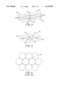
- FIG. 1 is a schematic enlarged view, illustrating various measurement parameters, of an industrial filament cut normal to its longitudinal axis showing a sinusoidal shaped cross section in accordance with the invention.
- FIG. 2 is a schematic enlarged view of a first tile arrangement of the filaments shown in FIG. 1 in an industrial yarn cut normal to its longitudinal axis.
- FIG. 3 is a schematic enlarged view of a second tile arrangement of the filaments shown in FIG. 1 in an industrial yarn cut normal to its longitudinal axis.
- FIG. 4 is a schematic enlarged view of a prior art arrangement of filaments having round cross sectional shapes in an industrial yarn cut normal to its longitudinal axis.
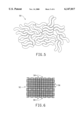
- FIG. 5 is a schematic enlarged view of an industrial yarn cut normal to its longitudinal axis in accordance with the present invention.
- FIG. 6 is a schematic enlarged view of one embodiment of a fabric in accordance with the present invention.
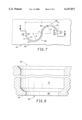
- FIG. 7 is a view of a spinneret orifice in a spinneret for spinning the filaments shown in FIG. 1.
- FIG. 8 is a cross sectional view generally along line 8--8 of the spinneret shown in FIG. 7 in the direction of the arrows.
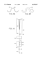
- FIGS. 9A and 9B illustrate an extended sinusoidal shaped spinneret orifice and an extended sinusoidal shaped cross section of a filament formed by spinning polymer through the extended sinusoidal shaped spinneret orifice.
- FIG. 10 is a schematic illustration of a spinning machine for producing yarns comprising the filaments shown in FIG. 1.
- FIGS. 11A and 11B illustrate a hollow bilobal shaped spinneret orifice and a hollow bilobal cross section of a filament formed by spinning polymer through the hollow bilobal shaped spinneret orifice.
- FIGS. 12A and 12B illustrate a hollow oval shaped spinneret orifice and a hollow oval cross section of a filament formed by spinning polymer through the hollow oval shaped spinneret orifice.
- FIGS. 13A and 13B illustrate a flat ribbon shaped spinneret orifice and a flat ribbon cross section of a filament formed by spinning polymer through the flat ribbon shaped spinneret orifice.
- FIGS. 14A and 14B illustrate a circular shaped spinneret orifice and a circular cross section of a filament formed by spinning polymer through the circular shaped spinneret orifice.
- the present invention is directed to an industrial filament 10 having a sinusoidal or "S" shaped cross section 12 and products made therefrom including multifilament yarns and fabrics.
- filament is defined as a relatively flexible, macroscopically homogeneous body having a high ratio of length to cross-sectional maximum width.
- fiber shall be used interchangeably with the term “filament”.
- the sinusoidal cross section 12 has a periphery 14 comprising, in a clockwise direction in FIG. 1, a first convex end 16, a first concave edge 18, a first convex edge 20, a second convex end 22, a second concave edge 24, and a second convex edge 26.
- the first convex edge 20 is defined by or substantially by a radius r1.
- the second concave edge 24 is also defined by or substantially defined by the radius r1.
- the second convex edge is defined by or substantially by a radius r2.
- first concave edge 18 is also defined by or substantially defined by the radius r2.
- the radius r1 can be different than the radius r2, but preferably r1 is equal to or substantially equal to r2.
- the first and second convex ends 16,22 are on distal sides of the periphery 14.
- the cross-sectional shape of the filament 10 can be quantitatively described by its aspect ratio (A/B).
- A/B aspect ratio
- the term "aspect ratio” has been given various definitions in the past.
- the term “aspect ratio” is defined as a ratio of a first dimension (A) to a second dimension (B).
- the first dimension (A) is defined as a length of a straight line segment connecting a first point 28 and a second point 30 in the periphery 14 of the filament cross section 12 that are farthest from one another.
- the first dimension (A) can also be defined as the diameter of a smallest circle 32 that will enclose the cross section 12 of the filament 10.
- the second dimension B is 2r where r is the sum of the radius r1 of the first outer convex edge 20 and the radius r2 of the second outer convex edge 26.
- r is the sum of the radius r1 of the first outer convex edge 20 and the radius r2 of the second outer convex edge 26.
- the aspect ratio of the sinusoidal cross section 12 of the present invention is about 2 to about 6, and preferably about 2.5 to about 5.
- a portion of a sinusoidal line 34 bisecting the cross section 12 with end points positioned on the first and second convex ends 16,22 of the cross section 12 is less than one complete cycle or period P of the sinusoidal line 34.
- industrial filaments with cross sections extending along a full cycle or more of the sinusoidal line 34 are within the scope of this invention.
- FIG. 9B illustrates such a filament 100.
- each one of the first outer convex edge 20 and the second outer convex edge 26 are less than a half cycle of the sinusoidal line 34.
- the cross sections 12 consist of entirely curved or arcuate, and no straight, edges or surfaces.
- the filaments 10,100 can be made from any and all types of synthetic polymers and mixtures thereof which are capable of being melt spun into filaments having industrial properties as specified herein.
- the polymers are polyesters or polyamides.
- Polyester polymer is used in this application to refer to polyester homopolymers and copolymers which are composed of at least 85% by weight of an ester of a dihydric alcohol and terephthalic acid.
- Some useful examples of polyesters and copolyesters are shown in U.S. Pat. Nos. 2,071,251 (to Carothers), 2,465,319 (to Whinfield and Dickson), 4,025,592 (to Bosley and Duncan), and 4,945,151 (to Goodley and Taylor).
- the polyester polymer used to make the filaments should be essentially 2G-T homopolymer, i.e., poly(ethylene terephthalate).
- Nylon polymer is used in this application to refer to polyamide homopolymers and copolymers which are predominantly aliphatic, i.e., less than 85% of the amide-linkages of the polymer are attached to two aromatic rings.
- Widely-used nylon polymers such as poly(hexamethylene adipamide) which is nylon 6,6 and poly(e-caproamide) which is nylon 6 and their copolymers can be used in accordance with the invention.
- Other nylon polymers which may be advantageously used are nylon 12, nylon 4,6, nylon 6,10 and nylon 6,12.
- Illustrative of polyamides and copolyamides which can be employed in the process of this invention are those described in U.S. Pat. Nos. 5,077,124, 5,106,946, and 5,139,729 (each to Cofer et al.) and the polyamide polymer blends disclosed by Gutmann in Chemical Fibers International, pages 418-420, Volume 46, December 1996.
- the polymers and resulting filaments 10,100, yarns and fabrics may contain the usual minor amounts of such additives as are known in the art, such as delustrants or pigments, light stabilizers, heat and oxidation stabilizers, additives for reducing static, additives for modifying dye ability, etc. Also as known in the art, the polymers must be of filament-forming molecular weight in order to melt spin into yarn.
- the filaments 10,100 of the present invention have a denier per filament (dpf) of about 4 to about 8 (about 4.4 dtex to about 8.9 dtex), and preferably about 6 to about 7.2 (about 6.6 dtex to about 8.0 dtex).
- dpf denier per filament
- These deniers are preferably measured deniers as described herein.
- the measured deniers are "as spun" measured average deniers which includes yarn finish and ambient moisture as described herein.
- the filaments 10,100 of the present invention have a tenacity of about 6.5 grams/denier to about 9.2 grams/denier, and preferably a tenacity of about 7.5 grams/denier to about 8.0 grams/denier.
- the filaments 10,100 of the present invention have a dry heat shrinkage of about 2% to about 16% at 30 minutes at 177° C., and preferably a dry heat shrinkage of about 3% to about 13% at 30 minutes at 177° C.
- the filaments 10,100 of the present invention have an elongation to break in the range of 16% to 29%, and preferably of 17% to 28%.
- a yarn comprises a plurality (typically 140-192) of the industrial filaments 10,100 having a degree of cohesion.
- the filaments 10,100 in a yarn are preferably intermingled and tangled through an intermingling device or otherwise.
- a typical intermingling device and process is disclosed in U.S. Pat. No. 2,985,995 and is suitable for use in the manufacture of the instant yarns.
- the filaments 10,100 with a sinusoidal cross section 12,112 have a tendency to naturally intermingle without the aid of an intermingling device.
- the term "yarn" as used herein includes continuous filaments and staple filaments, but are preferably continuous filaments.
- the filaments 10,100 are "continuous" meaning that the length of the filaments 10,100 making up the yarn are the same length as the yarn and are substantially the same length as other filaments in the yarn, in contrast to filaments in a yarn that are discontinuous which are often referred to as staple filaments or cut filaments formed into longer yarns much the same way that natural (cotton or wool) filaments are.
- the filaments 10 are positioned such that the ends 22 of a first set 36 of the filaments 10 are near, and aligned with, the ends 16 of a second set 38 of the filaments 10 such that pairs of the first set 36 of the filaments 10 and the second set 38 of the filaments 10 are positioned substantially along nonoverlapping sinusoidal lines 40.
- This first tile arrangement provides a very dense arrangement with minimum voids 42 between filaments 10.
- the filaments 10 are positioned such that inner concave surfaces 24 of a first set 44 of the filaments 10 contact inner concave surfaces 18 of a second set 46 of the filaments 10, outer convex surfaces 20 of the first set 44 of the filaments 10 contact outer convex surfaces 26 of the second set 46 of the filaments 10, such that the first set 44 of the filaments 10 and the second set 46 of the filaments 10 are positioned in a locked arrangement.
- the second tile arrangement provides a natural cohesion between the filaments 10.
- the first tile arrangement of the filaments 10 with the sinusoidal cross sections are more dense (i.e., have smaller void areas 42).
- the tile arrangements of FIGS. 2 and 3 provide a greater covering power than the arrangement of the filaments with round cross sections in FIG. 4.
- covering power means that the same volume or weight of filaments 10 with the sinusoidal cross sections covers or extends over a larger surface (left to right in FIGS.
- the elongated shape the filaments 10 with sinusoidal cross sections 12 give a bundle of the filaments 10 a tendency to spread out along a surface increasing the covering power or property when used, instead of filaments with round cross sections of similar construction and weight and having the same or substantially the same cross sectional area per filament.
- FIG. 5 is a schematic enlarged view of a portion of an industrial yarn 50 cut normal to its longitudinal axis in accordance with the present invention.
- the tile arrangements illustrated in FIGS. 2 and 3 can be seen throughout the yarn cross section in FIG. 5.
- Fabric The invention is further directed to industrial fabric 52 that includes at least one of the industrial yarns with at least some of the industrial filaments 10 in accordance with the invention.
- the filaments 10 produced in accordance with the present invention may be employed as yarns and converted, e.g., by weaving into fabric patterns of any conventional design by known methods. Furthermore, these bodies may be combined with other known filaments to produce mixed yarns and fabrics. Fabrics woven or knitted from, the filaments 10 produced in accord with this invention have increased covering power and reduced weight as compared to fabrics of similar construction and weight made from round filaments having the same cross sectional area per filament.
- the woven industrial fabric 52 comprises a plurality of first industrial yarns 54 in a warp direction, a plurality of second industrial yarns 56 in a fill direction weaved with the first industrial yarns 54, and at least some of the first industrial yarns 54 and/or at least some of the second industrial yarns 56 comprising a plurality of the industrial filaments 10.
- at least the first industrial yarns 54 or the second industrial yarns 56 comprise a plurality of the industrial filaments 10.
- the fabric 52 can have a reduction in total weight by at least 7% compared to a fabric made entirely from yarns comprising other filaments which are essentially the same as the industrial filaments, except the other filaments having circular cross sections.
- a range for fabric weight reduction (compared to a fabric made entirely from yarns comprising other filaments which are essentially the same as the industrial filaments 10, except the other filaments having circular cross sections) is from about 5% to about 15%.
- the woven industrial fabric 52 comprises a plurality of first industrial yarns 54 in a warp direction, a plurality of second industrial yarns 56 in a fill direction weaved with the first industrial yarns 54, and at least some of the first industrial yarns 54 and at least some of the second industrial yarns 56 comprising a plurality of the industrial filaments 10.
- the fabric 52 can have a reduction in total weight by at least 10% compared to a fabric entirely made from yarns comprising other filaments which are essentially the same as the industrial filaments 10, except the other filaments having circular cross sections.
- a range for fabric weight reduction using yarns made entirely of the filaments 10 is from about 10% to about 30%.
- FIGS. 7 and 8 illustrate a spinneret 60 for use in the melt extrusion of a synthetic polymer to produce the industrial filaments 10 having sinusoidal cross sections 12 in accordance with the present invention.
- the spinneret 60 comprises a plate 62 having an assembly of orifices, capillaries or holes 64 through which molten polymer is extruded to form the industrial filaments 10.
- FIG. 7 shows a bottom view of one of the orifices, capillaries or holes 64 having a sinusoidal shape or cross section 66 through the plate 62.
- the sinusoidal cross section 66 is normal to a longitudinal axis passing normal through the sheet of drawings through center point c of the orifices, capillaries or holes 64.
- FIG. 7 illustrates a spinneret 60 for use in the melt extrusion of a synthetic polymer to produce the industrial filaments 10 having sinusoidal cross sections 12 in accordance with the present invention.
- the spinneret 60 comprises a plate 62 having an assembly of orifices
- each hole 64 has two sections: a capillary 68 itself and a much larger and deeper counter bore passage 70 connected to the capillary 68.
- the sinusoidal cross section 66 of the capillary 68 has a periphery 71 comprising, in a clockwise direction in FIG. 7 and joined to one another, a first straight or substantially straight end 72, a first concave edge 73, a first convex edge 74, a second straight or substantially straight end 75, a second concave edge 76, and a second convex edge 77 joined to the first end 72.
- the first convex edge 74 is defined by or substantially defined by a radius r3.
- the second concave edge 76 is also defined by or substantially defined by the radius r3.
- the second convex edge 77 is defined by or substantially defined by a radius r4.
- the first concave edge 73 is also defined by or substantially defined by the radius r4.
- the radius r3 can be different than the radius r4, but preferably r3 is equal to or substantially equal to r4. Further, it is within the scope of this invention that r1, r2, r3, r4 can be all different lengths, all the same lengths or any mix of lengths.
- the cross-sectional shape 66 of the capillary 68 can also be quantitatively described by its aspect ratio (A/B).
- aspect ratio is defined as a ratio of a first dimension (A) to a second dimension (B).
- the first dimension (A) is defined as a length of a straight line segment connecting a first point and a second point in the periphery 71 of the capillary cross section 66 that are farthest from one another.
- the first dimension (A) can also be defined as the diameter of a smallest circle that will enclose the cross section 66 of the capillary 68.
- the second dimension B is 2r where r is the sum of the radius r3 of the first outer convex edge 74 and the radius r4 of the second outer convex edge 77.
- r is the sum of the radius r3 of the first outer convex edge 74 and the radius r4 of the second outer convex edge 77.
- the aspect ratio of the sinusoidal cross section 66 of the capillaries 68 of the present invention is about 1.3 to about 6, and preferably about 1.5 to about 2.5.
- a portion of a sinusoidal line 78 bisecting the cross section 66 with end points positioned on the first and second ends 72,75 of the capillary cross section 66 is less than one complete cycle or period P of the sinusoidal line 78.
- capillary cross sections 66 extending along a full cycle or more of the sinusoidal line 78 are within the scope of this invention.
- FIG. 9A illustrates such a capillary 164.
- each one of the first outer convex edge 74 and the second outer convex edge 77 are less than a half cycle of the sinusoidal line 78. This reduces the chances of the ends 22,28 joining with another point of the filament cross section 12 during the spinning process thereby reducing the chance that a filament cross section 12 will form with two holes, as illustrated in FIG. 11B, or one hole at one end.
- the spinneret 60 used in the production of filaments 10 of the present invention may be of any conventional material employed in spinneret construction for melt-spinning.
- the stainless steels are especially suitable.
- Each spinneret 60 may have from one to several thousand individual holes 64.
- the hole layout, or array, is carefully designed to keep filaments 10 properly separated, to permit each filament 10 the maximum unobstructed exposure to quench air, and to assure that all filaments 10 are treated as nearly equal as possible.
- the counter bore 70 can have a round cross section and can be formed by drilling.
- the capillaries 68 must be fabricated to precise dimensions such as with laser capillary machine.
- the shape of the spinneret capillary 68 determines the shape of the spun filament 10.
- the size of the individual filament 10 is controlled by the size of the capillary 68, the metering rate and the speed at which the filaments 10 are withdrawn from the quench zone and typically fixed by the rotational speed of the feed roll assembly, and not by capillary design alone. As such, the cross section 12 of the filaments 10 are smaller than the actual size of the capillary 68 through which they are produced.
- FIGS. 9A and 9B illustrate an extended sinusoidal shaped spinneret capillary 166 and an extended sinusoidal shaped cross section 112 of a filament 100 in accordance with this invention formed by spinning polymer through the extended sinusoidal shaped spinneret capillary 166.
- the filaments, yarns and fabrics of the present invention have market uses that include automobile airbags, industrial fabrics (architectural fabrics, signage, tarps, tents, etc.) sailcloth, tire cord, cordage (ropes), webbing, leisure fabrics, mechanical rubber goods, and others.
- Relative Viscosity Any relative viscosity (RV) measurement referred to herein is the unitless ratio of the viscosity of a 4.47 weight on weight percent solution of the polymer in hexafluoroisopropanol containing 100 ppm sulfuric acid to the viscosity of the solvent at 25° C. Using this solvent, the industrial yarns in the prior art, such as U.S. Pat. No. 3,216,817, have relative viscosities of at least 35.
- Denier is linear density and defined to be the number of unit weights of 0.05 gram per 450 meters (Man-Made Fiber and Textile Dictionary, Hoechst-Celanese, 1988). This definition is numerically equivalent to weight in grams per 9000 meters of the material. Another definition of linear density is Tex, the weight in grams of 1000 meters of material. The deciTex (dTex) is also widely used, equal to 1/10 of 1 Tex.
- measured denier is by the method of cutting a standard length of yarn and weighing.
- This ACW instrument is commercially available from LENZING AG, Division Lenzingtechnik, A-4860 Lenzing, Austria. Measured denier was by the ACW instrument method and based on 2 observations per yarn package. These two observations were averaged. Thus, the "measured" denier is an average denier.
- the yarn test specimen length was 22.5 meters and the specimen length tolerance was +/-1.0 cm. All ACW machine weights were within +/-0.2 milligram tolerance of certified standards used in machine calibration. The calculations for denier were based on the equation:
- a 22.5 meter length of yarn from a sample of 840 nominal denier yarn was cut and weighed by the ACW machine.
- This 22.5 meter sample should have a measured weight of 2.10 grams for the nominal and measured yarn denier to be identical at 840 denier (or 933.3 deciTex).
- the 1000 nominal denier yarns (or 1111 dTex) reported herein should have a weight of 2.50 grams for the nominal and measured yarn denier to be identical and the 1100 nominal denier yarns (or 1222 dTex) have a weight of 2.75 grams per 22.5 meters for the nominal and measured yarn denier to be identical.
- the "measured” yarn denier has been reported in the prior art in two ways. The first way is “as spun” measured denier which includes yarn finish and ambient moisture. Typically, our “nominal” 840 yarn denier is 847 measured denier "as spun”. The second way “measured” yarn denier is reported is “measured” yarn denier "as sold”.
- the term “as sold” does not mean the filaments were, in fact, sold or offered for sale. Instead, it means the yarn is prepared as if it was going to be sold prior to denier measurement. Prior to "as sold” denier measurement, the yarn finish is scoured off and the yarn standard moisture content is equilibrated at 0.4%. The “as sold” measured yarn denier is, by definition, equal to nominal denier or 840 in this case. All “measured” yarn denier reported herein is “as spun”, meaning the weight of yarn finish and ambient moisture is included in the calculation.
- Tensile Properties The tensile properties for the yarns reported herein are measured on an Instron Tensile Testing Machine (Type TTARB). The Instron extends a specified length of untwisted yarn to its breaking point at a given extension rate. Prior to tensile testing, all yarns are conditioned at 21.1 degrees C. and 65% relative humidity for 24 hours. Yarn "extension” and “breaking load” are automatically recorded on a stress-strain trace. For all yarn tensile tests herein, the sample length was 10 inches (25 cm), the extension rate was 12 inches/minute (30 cm) or 120%/minute, and the stress-strain chart speed was 12 inches/minute (30 cm/minute).
- Tenacity Yarn "tenacity” (T) was derived from the yarn breaking load. Tenacity (T) was measured using the Instron Tensile Tester Model 1122 which extends a 10-inch (25 cm) long yarn sample to its breaking point at an extension rate of 12 inch/min (30 cm/min) at a temperature of about 25° C. Extension and breaking load are automatically recorded on a stress-strain trace by the Instron. Tenacity is numerically defined by the breaking load in grams divided by the original yarn sample measured denier.
- Dry Heat Shrinkages are determined by exposing a measured length of yarn under zero tension to dry heat for 30 minutes in an oven maintained at the indicated temperatures (177 degrees C. for DHS177 and 140 degrees C. for DHS140) and by measuring the change in length. The shrinkages are expressed as percentages of the original length. DHS177 is most frequently measured for industrial yarns, we find DHS140 to give a better indication of the shrinkage that industrial yarns actually undergo during commercial coating operations, although the precise conditions vary according to proprietary processes.
- polyester filaments 80 were melt-spun from a spinneret 82, and solidified as they passed down within chimney 83 to become an undrawn multifilament yarn 84, which was advanced to the drawing stage by feed roll 85, the speed of which determined the spinning speed, i.e., the speed at which the solid filaments are withdrawn in the spinning step.
- the undrawn yarn 84 was advanced past heater 86, to become drawn yarn 87, by draw rolls 88 and 89, which rotated at the same speed, being higher than that of feed roll 85.
- the draw ratio is the ratio of the speed of draw rolls 88 and 89 to that of feed roll 85, and was generally between 4.7X and 6.4X.
- the drawn yarn 87 was annealed as it made multiple passes between draw rolls 88 and 9 within heated enclosure 90.
- the resulting yarn 92 was interlaced to provide coherency as it passed through interlacing jet 94.
- Interlace jet 94 provided heated air so that the interlaced yarn 95 was maintained at an elevated temperature as it was advanced to wind-up roll 96 where it was wound to form a yarn package.
- the interlaced yarn 95 was relaxed because it was overfed to wind-up roll 96, i.e., the speed of wind-up roll 96 was less than that of rolls 89 and 88. Finish was applied in conventional manner, not shown, generally being applied to undrawn yarn 84 before feed roll 85 and to drawn yarn 87 between heater 86 and heated enclosure 90.
- the draw roll speed was 3100 ypm (2835 meters/min). The properties were measured as described hereinafter. The process was followed using a steam jet at 360° C. for the heater 86, and a draw ratio of 5.9X between draw roll 88 and feed roll 85, heating rolls 88 and 89 to 240° C. within enclosure 90, overfeeding the yarn 13.5% between roll 89 and wind-up roll 96, so that the wind-up speed was 2680 ypm (about 2450 meters/min), and using interlacing air at 45 pounds per square inch (psi) and at 160° C. in jet 94.
- psi pounds per square inch
- a yarn of 840 nominal denier, 140 filaments and 37 relative viscosity was made using the process and apparatus described above.
- the yarn was made of filaments with round or circular cross-sections.
- the filaments were spun from polyester polymer (2GT) having 0.10% titanium dioxide as a delusterant, residual antimony catalyst at a level in the range of 300 to 400 parts per million, and small amounts of phosphorus in a range of 8 to 10 parts per million.
- the only other intentionally provided additive was a "toner", which was an anthraquinone dye, at level of 1 to 5 parts per million.
- the round cross-section yarn so produced had a good balance of shrinkage and tensile properties.
- the produced yarn had a measured "as spun" average denier of 847.
- the measured denier range was from 823 to 873.
- the yarn had a tenacity of 7.9 grams per denier and an elongation at break equal to 28%.
- the shrinkage (DHS177) of the yarn was 3.1%.
- Table 1 This Comparative Example shows the properties of a typical prior art Dacron® industrial yarn (with round filament cross sections as illustrated in FIG. 14B) sold by DuPont under designation 840-140-T51 and is a low shrinkage yarn. This prior art yarn packs together as the filament bundle illustrated by FIG. 4.
- This Comparative Example B yarn shows the properties of a typical prior art Dacron® industrial yarn sold by DuPont under designation 1000-192-T68, a high shrinkage yarn.
- Comparative Example H yarn shows the properties of a typical prior art Dacron® industrial yarn sold by DuPont under designation 840-140-T68, a high shrinkage yarn.
- Comparative Example I yarns were produced having 140 filaments with round cross sections as shown in FIG. 14B.
- the same shrinkage properties as for Comparative Example A yarns were measured.
- Table 1 This Comparative Example shows the properties of a typical prior art Dacron® industrial yarn sold by DuPont under designation 1100-140-T51, a low shrinkage yarn.
- Table 1 summarizes the properties of Comparative Example yarns A through I with the invention Example yarns 1, 2 and 3.
- the invention yarn properties particularly those properties consistent with industrial yarn applicability, e.g., tenacity and shrinkage, are shown by way of this Table 1 comparison to be substantially preserved regardless of filament cross sectional shape.
- the sinusoidal cross-section shaped filaments in the form of industrial polyester yarns are not different or substantially different from the prior art and other comparison yarns with respect to these properties.
- the surprising and distinguishing features of the inventive yarns are found in the properties of a fabric incorporating yarns with at least some of the sinusoidal cross section shaped filaments.
- a fabric was constructed from the Comparative Example H yarns in the warp direction with 19.5 yarns or picks per inch (ppi) and Example 3 yarns in the fill direction with 21 ppi.
- the fabric was visually rated for cover creating ability of the fill yarn by an observer using a light box for background illumination of the fabric.
- a 1-10 rating system was used with a rating of 1 given to the control fabric (Comparative Example O) and higher numbers given to indicate visually better covering power. Properties for and observations on this fabric are summarized in Table 2.
- a fabric was constructed from the Comparative Example H yarns in the warp direction with 19.5 ppi and Comparative Example D yarns in the fill direction with 21 ppi.
- the fabric was visually rated for cover creating ability of the fill yarn by an observer using a light box for background illumination of the fabric.
- a 1-10 rating system was used with a rating of 1 given to the control fabric (Comparative Example O) and higher numbers given to indicate visually better covering power.
- the resulting fabric was visually rated for cover power. Properties for and observations on this fabric are summarized in Table 2.
- a fabric was constructed from the Comparative Example H yarns in the warp direction with 19.5 ppi and Comparative Example E yarns in the fill direction with 21 ppi.
- the fabric was visually rated for cover creating ability of the fill yarn by an observer using a light box for background illumination of the fabric.
- a 1-10 rating system was used with a rating of 1 given to the control fabric (Comparative Example O) and higher numbers given to indicate visually better covering power.
- the resulting fabric was visually rated for cover power. Properties for and observations on this fabric are summarized in Table 2.
- a fabric was constructed from the Comparative Example H yarns in the warp direction with 19.5 ppi and Comparative Example F yarns in the fill direction with 21 ppi.
- the fabric was visually rated for cover creating ability of the fill yarn by an observer using a light box for background illumination of the fabric.
- a 1-10 rating system was used with a rating of 1 given to the control fabric (Comparative Example O) and higher numbers given to indicate visually better covering power.
- the resulting fabric was visually rated for cover power. Properties for and observations on this fabric are summarized in Table 2.
- a fabric was constructed from the Comparative Example H yarns in the warp direction with 19.5 ppi and Comparative Example G yarns in the fill direction with 21 ppi.
- the fabric was visually rated for cover creating ability of the fill yarn by an observer using a light box for background illumination of the fabric.
- a 1-10 rating system was used with a rating of 1 given to the control fabric (Comparative Example O) and higher numbers given to indicate visually better covering power.
- the resulting fabric was visually rated for cover power. Properties for and observations on this fabric are summarized in Table 2.
- a fabric was constructed from the Comparative Example H yarns in the warp direction with 19.5 ppi and Comparative Example I yarns in the fill direction with 21 ppi.
- the fabric was visually rated for cover creating ability of the fill yarn by an observer using a light box for background illumination of the fabric.
- a 1-10 rating system was used with a rating of 1 given to the control fabric (Comparative Example O) and higher numbers given to indicate visually better covering power.
- the resulting fabric was visually rated for cover power. Properties for and observations on this fabric are summarized in Table 2.
- a fabric was constructed from the Comparative Example H yarns in the warp direction with 19.5 ppi and Comparative Example A yarns in the fill direction with 21 ppi.
- the fabric was visually rated for cover creating ability of the fill yarn by an observer using a light box for background illumination of the fabric.
- a 1-10 rating system was used with a rating of 1 given to the control fabric (Comparative Example O) and higher numbers given to indicate visually better covering power.
- the resulting fabric was visually rated for cover power. Properties for and observations on this fabric are summarized in Table 2.
- Example O was the control fabric.
- the control fabric showed open fabric voids which were well-distributed throughout the fabric. The distribution of voids or spaces between yarns comprising the fabric allowed some light transmission when viewed against a light box, but appearance was otherwise uniform.
- a fabric was constructed from the Comparative Example H yarns in the warp direction with 19.5 ppi and the Example 1 yarns in the fill direction with 17.8 ppi. Comments comparing the cover power of this fabric to other fabrics are provided in Table 3. Further, the % weight reduction of this fabric versus the weight of Comparative Example O (control) fabric was calculated and is presented in Table 4.
- a fabric was constructed from the Comparative Example H yarns in the warp direction with 19.5 ppi and the Example 2 yarns in the fill direction with 15.8 ppi. Comments comparing the cover power of this fabric to other fabrics are provided in Table 3. Further, the % weight reduction of this fabric versus the weight of Comparative Example O (control) fabric was calculated and is presented in Table 4.
- a fabric was constructed from the Comparative Example H yarns in the warp direction with 19.5 ppi and the Comparative Example A yarns in the fill direction with 21.0 ppi. Comments comparing the cover power of this fabric to other fabrics are provided in Table 3.
- Example 5 and 6 show that an entirely commercially satisfactory fabric cover and appearance are obtained from the sinusoidal cross section filament yarns, even when present at a reduced fill-yarn count, versus round cross section filament yarns of denser weave. This result is surprising in view of the generally accepted strategy of using dense weaves to obtain more cover. Denser weaves are, however, produced at some additional expense. More fill yarns present in a weave slow the weaving process since the weaving machine requires more time to introduce the fill yarns. This result of Examples 5 and 6 demonstrated a faster weaving process is obtainable since the fill yarn count is reducible at a constant appearance property for the fabric. Furthermore, this reduced fill yarn count translates into a fabric weight savings versus higher fill counts.
- a fabric is constructed from the Example 2 yarns in the warp direction with 15.8 ppi and the Example 1 yarns in the fill direction with 15.8 ppi.
- the % weight reduction of this fabric versus the weight of Comparative Example O (control) fabric was calculated and is presented in Table 4.
Abstract
Description
D=(9000 meter×W(grams)/22.5 meters
                                  TABLE 1
__________________________________________________________________________
YARNS
       Nominal  Meas.
  Yarn No. Yarn Den/ (g/Den) shrink. aspect
  Den. Fil. Den. Fil. Ten. % ratio
__________________________________________________________________________
Comparative
  Examples
  A (FIG. 14B)  840 140  848 6.0 7.9 3.1 1
  B (FIG. 14B) 1000 140 1009 7.1 7.9 3.1 1
  C (FIG. 14B) 1000 192 1008 5.2 8.9 12.2 1
  D (FIG. 13B) 1100 140 1110 7.9 7.9 3.1 7
  E (FIG. 13B) 1000 140 1007 7.1 8.4 5.3 7
  F (FIG. 11B) 1000 140 1007 7.1 8.4 5.3 2.1
  G (FIG. 12B) 1100 140 1110 7.9 7.8 3.1 1.6
  H (FIG. 14B)  840 140  847 6.0 8.9 12.2 1
  I (FIG. 14B) 1100 140 1110 7.9 7.9 3.1 1
  Invention
  Examples
  1 (FIG. 1)  840 140  847 7.1 7.5 2.7 3.9
  2 (FIG. 1) 1000 140 1009 7.1 7.5 2.7 4
  3 (FIG. 1) 1000 192 1008 5.2 8.9 12.2 4
__________________________________________________________________________
              TABLE 2
______________________________________
FABRICS AND COVER RATINGS
  FOR: (19.5 warp yarns/inch) × (21 fill yarns/inch)
  FABRIC CONSTRUCTION
                     cover
  Example (warp × fill) rating comment
______________________________________
4      H × 3
                 9.5    Higher cover ability than Ex. K. Over-
     fills construction in a way not seen in
     Ex. J. Uniform appearance. No voids
     in fabric.
  J H × D 9.5 Higher cover ability than Ex. K. Fills
     construction with fill inferior to Ex. 4.
     Uniform appearance. No voids in fabric.
  K H × E 7 Higher cover ability than Ex. L. Fills
     fabric construction with fill inferior to
     Ex. 4. Uniformity slightly inferior to
     Ex. J. No voids in fabric.
  L H × F 5 Higher cover ability than Ex. M. Fills
     fabric construction with fill inferior to
     Ex. 4. Some slight voids in construc-
     tion.
  M H × G 3 Just slightly better cover than Ex. N.
     Some voids noted in construction and
     some non-uniformity.
  N H × I 2 Just slightly better cover than "control"
     with voids in fabric.
  O H × A 1 Well-distributed voids in construction of
   (control)  fabric.
______________________________________
              TABLE 3
______________________________________
FABRICS AND COVER RATINGS
  Control = O = H × A,
  (19.5 warp yarns/inch) × (21 fill yarns/inch)
  Invention = H in warp, (19.5 warp yarns/inch) ×
  (indicated fill yarns/inch)
           fabric     fill
   construction yarns/
  Example (warp × fill) inch comments
______________________________________
5      H × 1
                  17.8    Slightly better cover than control
     despite reduced fill yarn in fabric.
     Smooth uniform appearance with
     no fabric voids.
  6 H × 2 15.8 Slightly better cover than control.
     Smooth uniform appearance with
     no fabric voids.
  O H × A 21.0 Uniform cover with well
   (Control)  distributed fabric voids.
______________________________________
              TABLE 4
______________________________________
FABRIC WEIGHT REDUCTION
  O = Control
            warp yarns   fill yarns
                                % weight reduction
  Example per inch per inch vs. control (O)
______________________________________
O (=H × A)
        19.5         21       n/a
  5 (=H × 1) 19.5 17.8 13.6
  6 (=H × 2) 19.5 15.8 7.9
  7 (=2 × 1) 15.8 15.8 >17
______________________________________
Claims (13)
Priority Applications (7)
| Application Number | Priority Date | Filing Date | Title |
|---|---|---|---|
| US08/806,177 US6147017A (en) | 1997-02-26 | 1997-02-26 | Industrial fibers with sinusoidal cross sections and products made therefrom |
| DE1998182181 DE19882181T1 (en) | 1997-02-26 | 1998-02-25 | Industrial fibers with a sinusoidal cross-section and products made from them |
| GB9919215A GB2336561B (en) | 1997-02-26 | 1998-02-25 | Industrial fibers with sinusoidal cross sections and products made therefrom |
| KR10-1999-7007735A KR100493341B1 (en) | 1997-02-26 | 1998-02-25 | Industrial Fibers with Sinusoidal Cross Sections and Products Made Therefrom |
| BR9807247A BR9807247A (en) | 1997-02-26 | 1998-02-25 | Industrial filament, industrial yarn and industrial fabric |
| JP53779298A JP2001513852A (en) | 1997-02-26 | 1998-02-25 | Industrial fiber with sinusoidal cross section and products using it |
| PCT/US1998/003641 WO1998038359A1 (en) | 1997-02-26 | 1998-02-25 | Industrial fibers with sinusoidal cross sections and products made therefrom |
Applications Claiming Priority (1)
| Application Number | Priority Date | Filing Date | Title |
|---|---|---|---|
| US08/806,177 US6147017A (en) | 1997-02-26 | 1997-02-26 | Industrial fibers with sinusoidal cross sections and products made therefrom |
Publications (1)
| Publication Number | Publication Date |
|---|---|
| US6147017A true US6147017A (en) | 2000-11-14 |
Family
ID=25193501
Family Applications (1)
| Application Number | Title | Priority Date | Filing Date |
|---|---|---|---|
| US08/806,177 Expired - Fee Related US6147017A (en) | 1997-02-26 | 1997-02-26 | Industrial fibers with sinusoidal cross sections and products made therefrom |
Country Status (7)
| Country | Link |
|---|---|
| US (1) | US6147017A (en) |
| JP (1) | JP2001513852A (en) |
| KR (1) | KR100493341B1 (en) |
| BR (1) | BR9807247A (en) |
| DE (1) | DE19882181T1 (en) |
| GB (1) | GB2336561B (en) |
| WO (1) | WO1998038359A1 (en) |
Cited By (5)
| Publication number | Priority date | Publication date | Assignee | Title |
|---|---|---|---|---|
| US20010019928A1 (en) * | 1999-12-07 | 2001-09-06 | Susumu Takagi | Metal coated fiber materials |
| US20030008582A1 (en) * | 2000-08-17 | 2003-01-09 | Tomotaka Koketsu | Air-bag-use non-coat base cloth and air-bag-use fiber |
| WO2004106120A1 (en) | 2003-05-15 | 2004-12-09 | Invista Technologies S.A.R.L. | Polyester filament woven fabric for air bags |
| US20100325851A1 (en) * | 2009-06-25 | 2010-12-30 | Kolon Industries, Inc. | Method for manufacturing bulletproof fabric |
| US11248340B2 (en) * | 2018-01-17 | 2022-02-15 | Leoni Kabel Gmbh | Wire, in particular for a stranded wire |
Families Citing this family (2)
| Publication number | Priority date | Publication date | Assignee | Title |
|---|---|---|---|---|
| KR100957866B1 (en) * | 2007-10-24 | 2010-05-14 | 코오롱글로텍주식회사 | Modified cross-section Spinneret for artificial turf and spinning device including the same and the fiber prepared using the same |
| NL1036418C2 (en) | 2009-01-14 | 2010-07-15 | Ten Cate Thiolon Bv | PLASTIC FIBER AND AN ARTIFICIAL GRASS FIELD WITH SUCH FIBER. |
Citations (34)
| Publication number | Priority date | Publication date | Assignee | Title |
|---|---|---|---|---|
| US2071251A (en) * | 1931-07-03 | 1937-02-16 | Du Pont | Fiber and method of producing it |
| US2464746A (en) * | 1946-10-17 | 1949-03-15 | Gering Products Inc | Method of manufacturing thermoplastic pellets |
| US2465319A (en) * | 1941-07-29 | 1949-03-22 | Du Pont | Polymeric linear terephthalic esters |
| US2985995A (en) * | 1960-11-08 | 1961-05-30 | Du Pont | Compact interlaced yarn |
| US3060504A (en) * | 1958-12-17 | 1962-10-30 | Novacel Sa | Apparatus for making artificial chamois |
| US3164948A (en) * | 1963-02-28 | 1965-01-12 | Wall Rope Works Inc | Cordage and methods of manufacture thereof |
| US3216187A (en) * | 1962-01-02 | 1965-11-09 | Du Pont | High strength polyethylene terephthalate yarn |
| US3249669A (en) * | 1964-03-16 | 1966-05-03 | Du Pont | Process for making composite polyester filaments |
| JPS43523Y1 (en) * | 1966-05-27 | 1968-01-11 | ||
| GB1153543A (en) * | 1966-07-11 | 1969-05-29 | Snam Progetti | Spinneret Plate for Producing Filaments of Non-Circular Cross-Section and Filaments produced therewith |
| JPS482696U (en) * | 1971-05-29 | 1973-01-12 | ||
| US3914488A (en) * | 1973-09-24 | 1975-10-21 | Du Pont | Polyester filaments for fur-like fabrics |
| US4003974A (en) * | 1975-04-04 | 1977-01-18 | E. I. Du Pont De Nemours And Company | Continuous spin-drawing process for preparing polyethylene terephthalate yarns |
| US4025592A (en) * | 1975-08-13 | 1977-05-24 | E. I. Du Pont De Nemours And Company | Addition of diethylene glycol in continuous production of polyester yarn |
| US4054709A (en) * | 1975-07-17 | 1977-10-18 | Mikhail Nikolaevich Belitsin | Man-made fibre, yarn and textile produced therefrom |
| US4083914A (en) * | 1967-04-01 | 1978-04-11 | Barmag Barmer Maschinenfabrik Aktiengesellschaft | Methods for production of filaments from foils |
| SU631566A1 (en) * | 1976-04-06 | 1978-11-05 | Всесоюзный научно-исследовательский и экспериментальный институт по переработке химических волокон | Spinneret for shaping profiled chemical fibre |
| US4134951A (en) * | 1971-08-31 | 1979-01-16 | Smith & Nephew Polyfabrik Limited | Production of filaments |
| SU874771A1 (en) * | 1979-07-24 | 1981-10-23 | Всесоюзный научно-исследовательский институт синтетических волокон | Profiled chemical thread |
| US4332761A (en) * | 1977-01-26 | 1982-06-01 | Eastman Kodak Company | Process for manufacture of textile filaments and yarns |
| JPS58191212A (en) * | 1982-05-04 | 1983-11-08 | Teijin Ltd | Production of animal-hair like yarn |
| US4590032A (en) * | 1982-06-21 | 1986-05-20 | Eastman Kodak Company | Process for draw-fracturable yarn |
| US4622187A (en) * | 1984-05-23 | 1986-11-11 | E. I. Du Pont De Nemours And Company | Continuous process for making interlaced polyester yarns |
| US4634625A (en) * | 1984-10-25 | 1987-01-06 | E. I. Du Pont De Nemours And Company | New fabrics, yarns and process |
| US4680191A (en) * | 1985-02-05 | 1987-07-14 | Frito-Lay, Inc. | Cross-cut extrusion method |
| US4842792A (en) * | 1988-02-16 | 1989-06-27 | Eastman Kodak Company | Drafting process for preparing a modified polyester fiber |
| US4945151A (en) * | 1989-03-08 | 1990-07-31 | E. I. Du Pont De Nemours And Company | Continuous production of polyester filaments |
| US5006057A (en) * | 1988-02-16 | 1991-04-09 | Eastman Kodak Company | Modified grooved polyester fibers and spinneret for production thereof |
| US5077124A (en) * | 1989-10-20 | 1991-12-31 | E. I. Du Pont De Nemours And Company | Low shrinkage, high tenacity poly (hexamethylene adipamide) yarn and process for making same |
| US5106946A (en) * | 1989-10-20 | 1992-04-21 | E. I. Du Pont De Nemours And Company | High tenacity, high modulus polyamide yarn and process for making same |
| US5139729A (en) * | 1989-10-20 | 1992-08-18 | E. I. Du Pont De Nemours And Comapny | Process for making low shrinkage, high tenacity poly(epsilon-caproamide) yarn |
| US5294482A (en) * | 1989-04-28 | 1994-03-15 | Fiberweb North America, Inc. | Strong nonwoven fabric laminates from engineered multiconstituent fibers |
| WO1995001469A1 (en) * | 1993-06-30 | 1995-01-12 | E.I. Du Pont De Nemours And Company | Fiber bilobal cross sections and carpets prepared therefrom having a silk-like luster and soft hand |
| US5593768A (en) * | 1989-04-28 | 1997-01-14 | Fiberweb North America, Inc. | Nonwoven fabrics and fabric laminates from multiconstituent fibers |
-
1997
- 1997-02-26 US US08/806,177 patent/US6147017A/en not_active Expired - Fee Related
-
1998
- 1998-02-25 WO PCT/US1998/003641 patent/WO1998038359A1/en active IP Right Grant
- 1998-02-25 JP JP53779298A patent/JP2001513852A/en not_active Withdrawn
- 1998-02-25 GB GB9919215A patent/GB2336561B/en not_active Expired - Fee Related
- 1998-02-25 DE DE1998182181 patent/DE19882181T1/en not_active Ceased
- 1998-02-25 KR KR10-1999-7007735A patent/KR100493341B1/en not_active IP Right Cessation
- 1998-02-25 BR BR9807247A patent/BR9807247A/en active Search and Examination
Patent Citations (34)
| Publication number | Priority date | Publication date | Assignee | Title |
|---|---|---|---|---|
| US2071251A (en) * | 1931-07-03 | 1937-02-16 | Du Pont | Fiber and method of producing it |
| US2465319A (en) * | 1941-07-29 | 1949-03-22 | Du Pont | Polymeric linear terephthalic esters |
| US2464746A (en) * | 1946-10-17 | 1949-03-15 | Gering Products Inc | Method of manufacturing thermoplastic pellets |
| US3060504A (en) * | 1958-12-17 | 1962-10-30 | Novacel Sa | Apparatus for making artificial chamois |
| US2985995A (en) * | 1960-11-08 | 1961-05-30 | Du Pont | Compact interlaced yarn |
| US3216187A (en) * | 1962-01-02 | 1965-11-09 | Du Pont | High strength polyethylene terephthalate yarn |
| US3164948A (en) * | 1963-02-28 | 1965-01-12 | Wall Rope Works Inc | Cordage and methods of manufacture thereof |
| US3249669A (en) * | 1964-03-16 | 1966-05-03 | Du Pont | Process for making composite polyester filaments |
| JPS43523Y1 (en) * | 1966-05-27 | 1968-01-11 | ||
| GB1153543A (en) * | 1966-07-11 | 1969-05-29 | Snam Progetti | Spinneret Plate for Producing Filaments of Non-Circular Cross-Section and Filaments produced therewith |
| US4083914A (en) * | 1967-04-01 | 1978-04-11 | Barmag Barmer Maschinenfabrik Aktiengesellschaft | Methods for production of filaments from foils |
| JPS482696U (en) * | 1971-05-29 | 1973-01-12 | ||
| US4134951A (en) * | 1971-08-31 | 1979-01-16 | Smith & Nephew Polyfabrik Limited | Production of filaments |
| US3914488A (en) * | 1973-09-24 | 1975-10-21 | Du Pont | Polyester filaments for fur-like fabrics |
| US4003974A (en) * | 1975-04-04 | 1977-01-18 | E. I. Du Pont De Nemours And Company | Continuous spin-drawing process for preparing polyethylene terephthalate yarns |
| US4054709A (en) * | 1975-07-17 | 1977-10-18 | Mikhail Nikolaevich Belitsin | Man-made fibre, yarn and textile produced therefrom |
| US4025592A (en) * | 1975-08-13 | 1977-05-24 | E. I. Du Pont De Nemours And Company | Addition of diethylene glycol in continuous production of polyester yarn |
| SU631566A1 (en) * | 1976-04-06 | 1978-11-05 | Всесоюзный научно-исследовательский и экспериментальный институт по переработке химических волокон | Spinneret for shaping profiled chemical fibre |
| US4332761A (en) * | 1977-01-26 | 1982-06-01 | Eastman Kodak Company | Process for manufacture of textile filaments and yarns |
| SU874771A1 (en) * | 1979-07-24 | 1981-10-23 | Всесоюзный научно-исследовательский институт синтетических волокон | Profiled chemical thread |
| JPS58191212A (en) * | 1982-05-04 | 1983-11-08 | Teijin Ltd | Production of animal-hair like yarn |
| US4590032A (en) * | 1982-06-21 | 1986-05-20 | Eastman Kodak Company | Process for draw-fracturable yarn |
| US4622187A (en) * | 1984-05-23 | 1986-11-11 | E. I. Du Pont De Nemours And Company | Continuous process for making interlaced polyester yarns |
| US4634625A (en) * | 1984-10-25 | 1987-01-06 | E. I. Du Pont De Nemours And Company | New fabrics, yarns and process |
| US4680191A (en) * | 1985-02-05 | 1987-07-14 | Frito-Lay, Inc. | Cross-cut extrusion method |
| US5006057A (en) * | 1988-02-16 | 1991-04-09 | Eastman Kodak Company | Modified grooved polyester fibers and spinneret for production thereof |
| US4842792A (en) * | 1988-02-16 | 1989-06-27 | Eastman Kodak Company | Drafting process for preparing a modified polyester fiber |
| US4945151A (en) * | 1989-03-08 | 1990-07-31 | E. I. Du Pont De Nemours And Company | Continuous production of polyester filaments |
| US5294482A (en) * | 1989-04-28 | 1994-03-15 | Fiberweb North America, Inc. | Strong nonwoven fabric laminates from engineered multiconstituent fibers |
| US5593768A (en) * | 1989-04-28 | 1997-01-14 | Fiberweb North America, Inc. | Nonwoven fabrics and fabric laminates from multiconstituent fibers |
| US5077124A (en) * | 1989-10-20 | 1991-12-31 | E. I. Du Pont De Nemours And Company | Low shrinkage, high tenacity poly (hexamethylene adipamide) yarn and process for making same |
| US5106946A (en) * | 1989-10-20 | 1992-04-21 | E. I. Du Pont De Nemours And Company | High tenacity, high modulus polyamide yarn and process for making same |
| US5139729A (en) * | 1989-10-20 | 1992-08-18 | E. I. Du Pont De Nemours And Comapny | Process for making low shrinkage, high tenacity poly(epsilon-caproamide) yarn |
| WO1995001469A1 (en) * | 1993-06-30 | 1995-01-12 | E.I. Du Pont De Nemours And Company | Fiber bilobal cross sections and carpets prepared therefrom having a silk-like luster and soft hand |
Non-Patent Citations (4)
| Title |
|---|
| Gutmann, Improvement of polyamide yarn properties by processing polyamide blends, Chemical Fibers International , 46, 418 420, Dec. 1996. * |
| Gutmann, Improvement of polyamide yarn properties by processing polyamide blends, Chemical Fibers International, 46, 418-420, Dec. 1996. |
| Yoshimoto Masato, Production of Animal Hair Like Yarn, Patent Abtracts of Japan , vol. 008, No. 024, Feb. 2, 1984, & JP 58 191212 A (Teijin KK), Nov. 8, 1983. * |
| Yoshimoto Masato, Production of Animal-Hair Like Yarn, Patent Abtracts of Japan, vol. 008, No. 024, Feb. 2, 1984, & JP 58 191212 A (Teijin KK), Nov. 8, 1983. |
Cited By (9)
| Publication number | Priority date | Publication date | Assignee | Title |
|---|---|---|---|---|
| US20010019928A1 (en) * | 1999-12-07 | 2001-09-06 | Susumu Takagi | Metal coated fiber materials |
| US6924244B2 (en) * | 1999-12-07 | 2005-08-02 | Seiren Co., Ltd. | Metal coated fiber materials |
| US20030008582A1 (en) * | 2000-08-17 | 2003-01-09 | Tomotaka Koketsu | Air-bag-use non-coat base cloth and air-bag-use fiber |
| WO2004106120A1 (en) | 2003-05-15 | 2004-12-09 | Invista Technologies S.A.R.L. | Polyester filament woven fabric for air bags |
| US20060252322A1 (en) * | 2003-05-15 | 2006-11-09 | Invista Technologies, S.Ar.L. A Luxembourg Corporation | Polyester filament woven fabric for air bags |
| CN100415574C (en) * | 2003-05-15 | 2008-09-03 | 因温斯特技术公司 | Polyester filament woven fabric for air bags |
| US7498280B2 (en) * | 2003-05-15 | 2009-03-03 | Invista North America S.A.R.L. | Polyester filament woven fabric for air bags |
| US20100325851A1 (en) * | 2009-06-25 | 2010-12-30 | Kolon Industries, Inc. | Method for manufacturing bulletproof fabric |
| US11248340B2 (en) * | 2018-01-17 | 2022-02-15 | Leoni Kabel Gmbh | Wire, in particular for a stranded wire |
Also Published As
| Publication number | Publication date |
|---|---|
| GB9919215D0 (en) | 1999-10-20 |
| JP2001513852A (en) | 2001-09-04 |
| BR9807247A (en) | 2000-05-02 |
| GB2336561A (en) | 1999-10-27 |
| WO1998038359A1 (en) | 1998-09-03 |
| KR20000075669A (en) | 2000-12-26 |
| GB2336561B (en) | 2001-05-09 |
| KR100493341B1 (en) | 2005-06-02 |
| DE19882181T1 (en) | 2000-03-30 |
Similar Documents
| Publication | Publication Date | Title |
|---|---|---|
| EP1287190B1 (en) | Multilobal polymer filaments and articles produced therefrom | |
| US6803000B2 (en) | Process of making yarn from two types of polyester | |
| US7134265B2 (en) | Stretchable core-sheath type composite yarn and stretchable woven-knit fabric | |
| AU2001266607A1 (en) | Multilobal polymer filaments and articles produced therefrom | |
| US6037047A (en) | Industrial fibers with diamond cross sections and products made therefrom | |
| US8153253B2 (en) | Conjugate fiber-containing yarn | |
| US4712366A (en) | Denier-mixed composite yarn, denier-mixed special thick and thin yarn, false twist yarn and denier-mixed shrinkage-mixed composite yarn | |
| US6147017A (en) | Industrial fibers with sinusoidal cross sections and products made therefrom | |
| US20060051575A1 (en) | High shrinkage side by side type composite filament and a method for manufactruing the same | |
| US5922366A (en) | Spinnerets with diamond shaped capillaries | |
| WO1998038358A1 (en) | Spinnerets with sinusoidal shaped capillaries | |
| US6572967B1 (en) | Poly(trimethylene terephthalate) multifilament yarn | |
| MXPA99007869A (en) | Industrial fibers with sinusoidal cross sections and products made therefrom | |
| US4505867A (en) | Process for polyester yarns | |
| MXPA99007871A (en) | Industrial fibers with diamond cross sections and products made therefrom | |
| MXPA99007863A (en) | Spinnerets with diamond shaped capillaries | |
| EP1518948A1 (en) | Multilobal polymer filaments and articles produced therefrom | |
| JPH0232372B2 (en) | TOKUSHUKARYORIKAKOITONOSEIZOHOHO | |
| WO1997006295A1 (en) | Making high filament count fine filament polyester yarns | |
| JP2002327334A (en) | Method for producing polyester fiber |
Legal Events
| Date | Code | Title | Description |
|---|---|---|---|
| AS | Assignment |
Owner name: E.I. DU PONT DE NEMOURS AND COMPANY, DELAWARE Free format text: ASSIGNMENT OF ASSIGNORS INTEREST;ASSIGNORS:FASTENAU, ROBERT FRANCIS;SHORT, MARK ASHLEY;REEL/FRAME:008635/0891 Effective date: 19970527 |
|
| FPAY | Fee payment |
Year of fee payment: 4 |
|
| AS | Assignment |
Owner name: INVISTA NORTH AMERICA S.A.R.L., DELAWARE Free format text: ASSIGNMENT OF ASSIGNORS INTEREST;ASSIGNOR:E. I. DU PONT DE NEMOURS AND COMPANY;REEL/FRAME:015286/0708 Effective date: 20040430 |
|
| AS | Assignment |
Owner name: JPMORGAN CHASE BANK, N.A., TEXAS Free format text: SECURITY INTEREST;ASSIGNOR:INVISTA NORTH AMERICA S.A.R.L. F/K/A ARTEVA NORTH AMERICA S.A.R.;REEL/FRAME:015592/0824 Effective date: 20040430 |
|
| REMI | Maintenance fee reminder mailed | ||
| LAPS | Lapse for failure to pay maintenance fees | ||
| STCH | Information on status: patent discontinuation |
Free format text: PATENT EXPIRED DUE TO NONPAYMENT OF MAINTENANCE FEES UNDER 37 CFR 1.362 |
|
| FP | Lapsed due to failure to pay maintenance fee |
Effective date: 20081114 |
|
| AS | Assignment |
Owner name: DEUTSCHE BANK AG NEW YORK BRANCH, AS COLLATERAL AG Free format text: SECURITY AGREEMENT;ASSIGNOR:INVISTA NORTH AMERICA S.A.R.L.;REEL/FRAME:022416/0849 Effective date: 20090206 Owner name: INVISTA NORTH AMERICA S.A.R.L. (F/K/A ARTEVA NORTH Free format text: RELEASE OF U.S. PATENT SECURITY INTEREST;ASSIGNOR:JPMORGAN CHASE BANK, N.A., AS ADMINISTRATIVE AGENT AND COLLATERAL AGENT (F/K/A JPMORGAN CHASE BANK);REEL/FRAME:022427/0001 Effective date: 20090206 |
|
| AS | Assignment |
Owner name: INVISTA NORTH AMERICA S.A.R.L., NORTH CAROLINA Free format text: RELEASE BY SECURED PARTY;ASSIGNOR:DEUTSCHE BANK AG NEW YORK BRANCH;REEL/FRAME:027211/0298 Effective date: 20111110 |