US6142520A - Air bag - Google Patents
Air bag Download PDFInfo
- Publication number
- US6142520A US6142520A US08/907,864 US90786497A US6142520A US 6142520 A US6142520 A US 6142520A US 90786497 A US90786497 A US 90786497A US 6142520 A US6142520 A US 6142520A
- Authority
- US
- United States
- Prior art keywords
- layer
- air bag
- elastomer
- laminated
- layers
- Prior art date
- Legal status (The legal status is an assumption and is not a legal conclusion. Google has not performed a legal analysis and makes no representation as to the accuracy of the status listed.)
- Expired - Fee Related
Links
- 229920001971 elastomer Polymers 0.000 claims abstract description 59
- 239000000806 elastomer Substances 0.000 claims abstract description 59
- 230000003014 reinforcing effect Effects 0.000 claims description 12
- 229920002725 thermoplastic elastomer Polymers 0.000 claims description 8
- 238000003780 insertion Methods 0.000 claims description 6
- 230000037431 insertion Effects 0.000 claims description 6
- JOYRKODLDBILNP-UHFFFAOYSA-N Ethyl urethane Chemical compound CCOC(N)=O JOYRKODLDBILNP-UHFFFAOYSA-N 0.000 claims description 4
- 239000004952 Polyamide Substances 0.000 claims description 4
- 239000004642 Polyimide Substances 0.000 claims description 4
- 150000001408 amides Chemical class 0.000 claims description 4
- 150000002148 esters Chemical class 0.000 claims description 4
- 229920002647 polyamide Polymers 0.000 claims description 4
- 229920000515 polycarbonate Polymers 0.000 claims description 4
- 239000004417 polycarbonate Substances 0.000 claims description 4
- 229920001721 polyimide Polymers 0.000 claims description 4
- 229920000728 polyester Polymers 0.000 claims description 3
- 239000012815 thermoplastic material Substances 0.000 claims 1
- 239000010410 layer Substances 0.000 description 101
- 230000002093 peripheral effect Effects 0.000 description 11
- 229920005989 resin Polymers 0.000 description 11
- 239000011347 resin Substances 0.000 description 11
- 238000003475 lamination Methods 0.000 description 8
- 239000000463 material Substances 0.000 description 8
- 230000035939 shock Effects 0.000 description 7
- 238000010521 absorption reaction Methods 0.000 description 6
- 238000007789 sealing Methods 0.000 description 6
- 238000001125 extrusion Methods 0.000 description 4
- 239000002759 woven fabric Substances 0.000 description 4
- 238000000034 method Methods 0.000 description 3
- 239000002356 single layer Substances 0.000 description 3
- 238000007765 extrusion coating Methods 0.000 description 2
- 230000002349 favourable effect Effects 0.000 description 2
- 239000007789 gas Substances 0.000 description 2
- IJGRMHOSHXDMSA-UHFFFAOYSA-N Atomic nitrogen Chemical compound N#N IJGRMHOSHXDMSA-UHFFFAOYSA-N 0.000 description 1
- 206010039203 Road traffic accident Diseases 0.000 description 1
- 239000004809 Teflon Substances 0.000 description 1
- 229920006362 Teflon® Polymers 0.000 description 1
- 239000000853 adhesive Substances 0.000 description 1
- 230000001070 adhesive effect Effects 0.000 description 1
- 239000012790 adhesive layer Substances 0.000 description 1
- 230000015572 biosynthetic process Effects 0.000 description 1
- 239000011248 coating agent Substances 0.000 description 1
- 238000000576 coating method Methods 0.000 description 1
- 239000012141 concentrate Substances 0.000 description 1
- 238000007796 conventional method Methods 0.000 description 1
- 229910001873 dinitrogen Inorganic materials 0.000 description 1
- 238000009820 dry lamination Methods 0.000 description 1
- 230000000694 effects Effects 0.000 description 1
- 238000005516 engineering process Methods 0.000 description 1
- 230000009975 flexible effect Effects 0.000 description 1
- 238000010030 laminating Methods 0.000 description 1
- 230000035515 penetration Effects 0.000 description 1
- 230000002787 reinforcement Effects 0.000 description 1
- 230000000452 restraining effect Effects 0.000 description 1
- 238000007493 shaping process Methods 0.000 description 1
- 229920005992 thermoplastic resin Polymers 0.000 description 1
- 238000003466 welding Methods 0.000 description 1
Images


Classifications
-
- B—PERFORMING OPERATIONS; TRANSPORTING
- B60—VEHICLES IN GENERAL
- B60R—VEHICLES, VEHICLE FITTINGS, OR VEHICLE PARTS, NOT OTHERWISE PROVIDED FOR
- B60R21/00—Arrangements or fittings on vehicles for protecting or preventing injuries to occupants or pedestrians in case of accidents or other traffic risks
- B60R21/02—Occupant safety arrangements or fittings, e.g. crash pads
- B60R21/16—Inflatable occupant restraints or confinements designed to inflate upon impact or impending impact, e.g. air bags
- B60R21/23—Inflatable members
- B60R21/235—Inflatable members characterised by their material
-
- B—PERFORMING OPERATIONS; TRANSPORTING
- B29—WORKING OF PLASTICS; WORKING OF SUBSTANCES IN A PLASTIC STATE IN GENERAL
- B29C—SHAPING OR JOINING OF PLASTICS; SHAPING OF MATERIAL IN A PLASTIC STATE, NOT OTHERWISE PROVIDED FOR; AFTER-TREATMENT OF THE SHAPED PRODUCTS, e.g. REPAIRING
- B29C65/00—Joining or sealing of preformed parts, e.g. welding of plastics materials; Apparatus therefor
- B29C65/02—Joining or sealing of preformed parts, e.g. welding of plastics materials; Apparatus therefor by heating, with or without pressure
- B29C65/04—Dielectric heating, e.g. high-frequency welding, i.e. radio frequency welding of plastic materials having dielectric properties, e.g. PVC
-
- B—PERFORMING OPERATIONS; TRANSPORTING
- B29—WORKING OF PLASTICS; WORKING OF SUBSTANCES IN A PLASTIC STATE IN GENERAL
- B29C—SHAPING OR JOINING OF PLASTICS; SHAPING OF MATERIAL IN A PLASTIC STATE, NOT OTHERWISE PROVIDED FOR; AFTER-TREATMENT OF THE SHAPED PRODUCTS, e.g. REPAIRING
- B29C65/00—Joining or sealing of preformed parts, e.g. welding of plastics materials; Apparatus therefor
- B29C65/48—Joining or sealing of preformed parts, e.g. welding of plastics materials; Apparatus therefor using adhesives, i.e. using supplementary joining material; solvent bonding
- B29C65/4805—Joining or sealing of preformed parts, e.g. welding of plastics materials; Apparatus therefor using adhesives, i.e. using supplementary joining material; solvent bonding characterised by the type of adhesives
- B29C65/481—Non-reactive adhesives, e.g. physically hardening adhesives
- B29C65/4815—Hot melt adhesives, e.g. thermoplastic adhesives
-
- B—PERFORMING OPERATIONS; TRANSPORTING
- B29—WORKING OF PLASTICS; WORKING OF SUBSTANCES IN A PLASTIC STATE IN GENERAL
- B29C—SHAPING OR JOINING OF PLASTICS; SHAPING OF MATERIAL IN A PLASTIC STATE, NOT OTHERWISE PROVIDED FOR; AFTER-TREATMENT OF THE SHAPED PRODUCTS, e.g. REPAIRING
- B29C65/00—Joining or sealing of preformed parts, e.g. welding of plastics materials; Apparatus therefor
- B29C65/48—Joining or sealing of preformed parts, e.g. welding of plastics materials; Apparatus therefor using adhesives, i.e. using supplementary joining material; solvent bonding
- B29C65/50—Joining or sealing of preformed parts, e.g. welding of plastics materials; Apparatus therefor using adhesives, i.e. using supplementary joining material; solvent bonding using adhesive tape, e.g. thermoplastic tape; using threads or the like
- B29C65/5007—Joining or sealing of preformed parts, e.g. welding of plastics materials; Apparatus therefor using adhesives, i.e. using supplementary joining material; solvent bonding using adhesive tape, e.g. thermoplastic tape; using threads or the like characterised by the structure of said adhesive tape, threads or the like
- B29C65/5021—Joining or sealing of preformed parts, e.g. welding of plastics materials; Apparatus therefor using adhesives, i.e. using supplementary joining material; solvent bonding using adhesive tape, e.g. thermoplastic tape; using threads or the like characterised by the structure of said adhesive tape, threads or the like being multi-layered
-
- B—PERFORMING OPERATIONS; TRANSPORTING
- B29—WORKING OF PLASTICS; WORKING OF SUBSTANCES IN A PLASTIC STATE IN GENERAL
- B29C—SHAPING OR JOINING OF PLASTICS; SHAPING OF MATERIAL IN A PLASTIC STATE, NOT OTHERWISE PROVIDED FOR; AFTER-TREATMENT OF THE SHAPED PRODUCTS, e.g. REPAIRING
- B29C65/00—Joining or sealing of preformed parts, e.g. welding of plastics materials; Apparatus therefor
- B29C65/48—Joining or sealing of preformed parts, e.g. welding of plastics materials; Apparatus therefor using adhesives, i.e. using supplementary joining material; solvent bonding
- B29C65/50—Joining or sealing of preformed parts, e.g. welding of plastics materials; Apparatus therefor using adhesives, i.e. using supplementary joining material; solvent bonding using adhesive tape, e.g. thermoplastic tape; using threads or the like
- B29C65/5057—Joining or sealing of preformed parts, e.g. welding of plastics materials; Apparatus therefor using adhesives, i.e. using supplementary joining material; solvent bonding using adhesive tape, e.g. thermoplastic tape; using threads or the like positioned between the surfaces to be joined
-
- B—PERFORMING OPERATIONS; TRANSPORTING
- B29—WORKING OF PLASTICS; WORKING OF SUBSTANCES IN A PLASTIC STATE IN GENERAL
- B29C—SHAPING OR JOINING OF PLASTICS; SHAPING OF MATERIAL IN A PLASTIC STATE, NOT OTHERWISE PROVIDED FOR; AFTER-TREATMENT OF THE SHAPED PRODUCTS, e.g. REPAIRING
- B29C65/00—Joining or sealing of preformed parts, e.g. welding of plastics materials; Apparatus therefor
- B29C65/48—Joining or sealing of preformed parts, e.g. welding of plastics materials; Apparatus therefor using adhesives, i.e. using supplementary joining material; solvent bonding
- B29C65/50—Joining or sealing of preformed parts, e.g. welding of plastics materials; Apparatus therefor using adhesives, i.e. using supplementary joining material; solvent bonding using adhesive tape, e.g. thermoplastic tape; using threads or the like
- B29C65/5064—Joining or sealing of preformed parts, e.g. welding of plastics materials; Apparatus therefor using adhesives, i.e. using supplementary joining material; solvent bonding using adhesive tape, e.g. thermoplastic tape; using threads or the like of particular form, e.g. being C-shaped, T-shaped
- B29C65/5071—Joining or sealing of preformed parts, e.g. welding of plastics materials; Apparatus therefor using adhesives, i.e. using supplementary joining material; solvent bonding using adhesive tape, e.g. thermoplastic tape; using threads or the like of particular form, e.g. being C-shaped, T-shaped and being composed by one single element
-
- B—PERFORMING OPERATIONS; TRANSPORTING
- B29—WORKING OF PLASTICS; WORKING OF SUBSTANCES IN A PLASTIC STATE IN GENERAL
- B29C—SHAPING OR JOINING OF PLASTICS; SHAPING OF MATERIAL IN A PLASTIC STATE, NOT OTHERWISE PROVIDED FOR; AFTER-TREATMENT OF THE SHAPED PRODUCTS, e.g. REPAIRING
- B29C66/00—General aspects of processes or apparatus for joining preformed parts
- B29C66/004—Preventing sticking together, e.g. of some areas of the parts to be joined
-
- B—PERFORMING OPERATIONS; TRANSPORTING
- B29—WORKING OF PLASTICS; WORKING OF SUBSTANCES IN A PLASTIC STATE IN GENERAL
- B29C—SHAPING OR JOINING OF PLASTICS; SHAPING OF MATERIAL IN A PLASTIC STATE, NOT OTHERWISE PROVIDED FOR; AFTER-TREATMENT OF THE SHAPED PRODUCTS, e.g. REPAIRING
- B29C66/00—General aspects of processes or apparatus for joining preformed parts
- B29C66/01—General aspects dealing with the joint area or with the area to be joined
- B29C66/05—Particular design of joint configurations
- B29C66/10—Particular design of joint configurations particular design of the joint cross-sections
- B29C66/13—Single flanged joints; Fin-type joints; Single hem joints; Edge joints; Interpenetrating fingered joints; Other specific particular designs of joint cross-sections not provided for in groups B29C66/11 - B29C66/12
- B29C66/133—Fin-type joints, the parts to be joined being flexible
-
- B—PERFORMING OPERATIONS; TRANSPORTING
- B29—WORKING OF PLASTICS; WORKING OF SUBSTANCES IN A PLASTIC STATE IN GENERAL
- B29C—SHAPING OR JOINING OF PLASTICS; SHAPING OF MATERIAL IN A PLASTIC STATE, NOT OTHERWISE PROVIDED FOR; AFTER-TREATMENT OF THE SHAPED PRODUCTS, e.g. REPAIRING
- B29C66/00—General aspects of processes or apparatus for joining preformed parts
- B29C66/40—General aspects of joining substantially flat articles, e.g. plates, sheets or web-like materials; Making flat seams in tubular or hollow articles; Joining single elements to substantially flat surfaces
- B29C66/41—Joining substantially flat articles ; Making flat seams in tubular or hollow articles
- B29C66/43—Joining a relatively small portion of the surface of said articles
-
- B—PERFORMING OPERATIONS; TRANSPORTING
- B29—WORKING OF PLASTICS; WORKING OF SUBSTANCES IN A PLASTIC STATE IN GENERAL
- B29C—SHAPING OR JOINING OF PLASTICS; SHAPING OF MATERIAL IN A PLASTIC STATE, NOT OTHERWISE PROVIDED FOR; AFTER-TREATMENT OF THE SHAPED PRODUCTS, e.g. REPAIRING
- B29C66/00—General aspects of processes or apparatus for joining preformed parts
- B29C66/70—General aspects of processes or apparatus for joining preformed parts characterised by the composition, physical properties or the structure of the material of the parts to be joined; Joining with non-plastics material
- B29C66/72—General aspects of processes or apparatus for joining preformed parts characterised by the composition, physical properties or the structure of the material of the parts to be joined; Joining with non-plastics material characterised by the structure of the material of the parts to be joined
- B29C66/723—General aspects of processes or apparatus for joining preformed parts characterised by the composition, physical properties or the structure of the material of the parts to be joined; Joining with non-plastics material characterised by the structure of the material of the parts to be joined being multi-layered
-
- B—PERFORMING OPERATIONS; TRANSPORTING
- B29—WORKING OF PLASTICS; WORKING OF SUBSTANCES IN A PLASTIC STATE IN GENERAL
- B29C—SHAPING OR JOINING OF PLASTICS; SHAPING OF MATERIAL IN A PLASTIC STATE, NOT OTHERWISE PROVIDED FOR; AFTER-TREATMENT OF THE SHAPED PRODUCTS, e.g. REPAIRING
- B29C66/00—General aspects of processes or apparatus for joining preformed parts
- B29C66/70—General aspects of processes or apparatus for joining preformed parts characterised by the composition, physical properties or the structure of the material of the parts to be joined; Joining with non-plastics material
- B29C66/73—General aspects of processes or apparatus for joining preformed parts characterised by the composition, physical properties or the structure of the material of the parts to be joined; Joining with non-plastics material characterised by the intensive physical properties of the material of the parts to be joined, by the optical properties of the material of the parts to be joined, by the extensive physical properties of the parts to be joined, by the state of the material of the parts to be joined or by the material of the parts to be joined being a thermoplastic or a thermoset
- B29C66/739—General aspects of processes or apparatus for joining preformed parts characterised by the composition, physical properties or the structure of the material of the parts to be joined; Joining with non-plastics material characterised by the intensive physical properties of the material of the parts to be joined, by the optical properties of the material of the parts to be joined, by the extensive physical properties of the parts to be joined, by the state of the material of the parts to be joined or by the material of the parts to be joined being a thermoplastic or a thermoset characterised by the material of the parts to be joined being a thermoplastic or a thermoset
- B29C66/7392—General aspects of processes or apparatus for joining preformed parts characterised by the composition, physical properties or the structure of the material of the parts to be joined; Joining with non-plastics material characterised by the intensive physical properties of the material of the parts to be joined, by the optical properties of the material of the parts to be joined, by the extensive physical properties of the parts to be joined, by the state of the material of the parts to be joined or by the material of the parts to be joined being a thermoplastic or a thermoset characterised by the material of the parts to be joined being a thermoplastic or a thermoset characterised by the material of at least one of the parts being a thermoplastic
- B29C66/73921—General aspects of processes or apparatus for joining preformed parts characterised by the composition, physical properties or the structure of the material of the parts to be joined; Joining with non-plastics material characterised by the intensive physical properties of the material of the parts to be joined, by the optical properties of the material of the parts to be joined, by the extensive physical properties of the parts to be joined, by the state of the material of the parts to be joined or by the material of the parts to be joined being a thermoplastic or a thermoset characterised by the material of the parts to be joined being a thermoplastic or a thermoset characterised by the material of at least one of the parts being a thermoplastic characterised by the materials of both parts being thermoplastics
-
- B—PERFORMING OPERATIONS; TRANSPORTING
- B29—WORKING OF PLASTICS; WORKING OF SUBSTANCES IN A PLASTIC STATE IN GENERAL
- B29C—SHAPING OR JOINING OF PLASTICS; SHAPING OF MATERIAL IN A PLASTIC STATE, NOT OTHERWISE PROVIDED FOR; AFTER-TREATMENT OF THE SHAPED PRODUCTS, e.g. REPAIRING
- B29C66/00—General aspects of processes or apparatus for joining preformed parts
- B29C66/80—General aspects of machine operations or constructions and parts thereof
- B29C66/81—General aspects of the pressing elements, i.e. the elements applying pressure on the parts to be joined in the area to be joined, e.g. the welding jaws or clamps
- B29C66/814—General aspects of the pressing elements, i.e. the elements applying pressure on the parts to be joined in the area to be joined, e.g. the welding jaws or clamps characterised by the design of the pressing elements, e.g. of the welding jaws or clamps
- B29C66/8141—General aspects of the pressing elements, i.e. the elements applying pressure on the parts to be joined in the area to be joined, e.g. the welding jaws or clamps characterised by the design of the pressing elements, e.g. of the welding jaws or clamps characterised by the surface geometry of the part of the pressing elements, e.g. welding jaws or clamps, coming into contact with the parts to be joined
- B29C66/81431—General aspects of the pressing elements, i.e. the elements applying pressure on the parts to be joined in the area to be joined, e.g. the welding jaws or clamps characterised by the design of the pressing elements, e.g. of the welding jaws or clamps characterised by the surface geometry of the part of the pressing elements, e.g. welding jaws or clamps, coming into contact with the parts to be joined comprising a single cavity, e.g. a groove
-
- B—PERFORMING OPERATIONS; TRANSPORTING
- B29—WORKING OF PLASTICS; WORKING OF SUBSTANCES IN A PLASTIC STATE IN GENERAL
- B29C—SHAPING OR JOINING OF PLASTICS; SHAPING OF MATERIAL IN A PLASTIC STATE, NOT OTHERWISE PROVIDED FOR; AFTER-TREATMENT OF THE SHAPED PRODUCTS, e.g. REPAIRING
- B29C66/00—General aspects of processes or apparatus for joining preformed parts
- B29C66/80—General aspects of machine operations or constructions and parts thereof
- B29C66/83—General aspects of machine operations or constructions and parts thereof characterised by the movement of the joining or pressing tools
- B29C66/832—Reciprocating joining or pressing tools
- B29C66/8322—Joining or pressing tools reciprocating along one axis
- B29C66/83221—Joining or pressing tools reciprocating along one axis cooperating reciprocating tools, each tool reciprocating along one axis
-
- B—PERFORMING OPERATIONS; TRANSPORTING
- B32—LAYERED PRODUCTS
- B32B—LAYERED PRODUCTS, i.e. PRODUCTS BUILT-UP OF STRATA OF FLAT OR NON-FLAT, e.g. CELLULAR OR HONEYCOMB, FORM
- B32B25/00—Layered products comprising a layer of natural or synthetic rubber
- B32B25/04—Layered products comprising a layer of natural or synthetic rubber comprising rubber as the main or only constituent of a layer, which is next to another layer of the same or of a different material
- B32B25/08—Layered products comprising a layer of natural or synthetic rubber comprising rubber as the main or only constituent of a layer, which is next to another layer of the same or of a different material of synthetic resin
-
- B—PERFORMING OPERATIONS; TRANSPORTING
- B29—WORKING OF PLASTICS; WORKING OF SUBSTANCES IN A PLASTIC STATE IN GENERAL
- B29C—SHAPING OR JOINING OF PLASTICS; SHAPING OF MATERIAL IN A PLASTIC STATE, NOT OTHERWISE PROVIDED FOR; AFTER-TREATMENT OF THE SHAPED PRODUCTS, e.g. REPAIRING
- B29C65/00—Joining or sealing of preformed parts, e.g. welding of plastics materials; Apparatus therefor
- B29C65/48—Joining or sealing of preformed parts, e.g. welding of plastics materials; Apparatus therefor using adhesives, i.e. using supplementary joining material; solvent bonding
- B29C65/50—Joining or sealing of preformed parts, e.g. welding of plastics materials; Apparatus therefor using adhesives, i.e. using supplementary joining material; solvent bonding using adhesive tape, e.g. thermoplastic tape; using threads or the like
- B29C65/5007—Joining or sealing of preformed parts, e.g. welding of plastics materials; Apparatus therefor using adhesives, i.e. using supplementary joining material; solvent bonding using adhesive tape, e.g. thermoplastic tape; using threads or the like characterised by the structure of said adhesive tape, threads or the like
- B29C65/5028—Joining or sealing of preformed parts, e.g. welding of plastics materials; Apparatus therefor using adhesives, i.e. using supplementary joining material; solvent bonding using adhesive tape, e.g. thermoplastic tape; using threads or the like characterised by the structure of said adhesive tape, threads or the like being textile in woven or non-woven form
-
- B—PERFORMING OPERATIONS; TRANSPORTING
- B29—WORKING OF PLASTICS; WORKING OF SUBSTANCES IN A PLASTIC STATE IN GENERAL
- B29C—SHAPING OR JOINING OF PLASTICS; SHAPING OF MATERIAL IN A PLASTIC STATE, NOT OTHERWISE PROVIDED FOR; AFTER-TREATMENT OF THE SHAPED PRODUCTS, e.g. REPAIRING
- B29C66/00—General aspects of processes or apparatus for joining preformed parts
- B29C66/70—General aspects of processes or apparatus for joining preformed parts characterised by the composition, physical properties or the structure of the material of the parts to be joined; Joining with non-plastics material
- B29C66/71—General aspects of processes or apparatus for joining preformed parts characterised by the composition, physical properties or the structure of the material of the parts to be joined; Joining with non-plastics material characterised by the composition of the plastics material of the parts to be joined
-
- B—PERFORMING OPERATIONS; TRANSPORTING
- B29—WORKING OF PLASTICS; WORKING OF SUBSTANCES IN A PLASTIC STATE IN GENERAL
- B29K—INDEXING SCHEME ASSOCIATED WITH SUBCLASSES B29B, B29C OR B29D, RELATING TO MOULDING MATERIALS OR TO MATERIALS FOR MOULDS, REINFORCEMENTS, FILLERS OR PREFORMED PARTS, e.g. INSERTS
- B29K2995/00—Properties of moulding materials, reinforcements, fillers, preformed parts or moulds
- B29K2995/0037—Other properties
- B29K2995/007—Hardness
-
- B—PERFORMING OPERATIONS; TRANSPORTING
- B29—WORKING OF PLASTICS; WORKING OF SUBSTANCES IN A PLASTIC STATE IN GENERAL
- B29L—INDEXING SCHEME ASSOCIATED WITH SUBCLASS B29C, RELATING TO PARTICULAR ARTICLES
- B29L2022/00—Hollow articles
- B29L2022/02—Inflatable articles
- B29L2022/027—Air bags
-
- B—PERFORMING OPERATIONS; TRANSPORTING
- B60—VEHICLES IN GENERAL
- B60R—VEHICLES, VEHICLE FITTINGS, OR VEHICLE PARTS, NOT OTHERWISE PROVIDED FOR
- B60R21/00—Arrangements or fittings on vehicles for protecting or preventing injuries to occupants or pedestrians in case of accidents or other traffic risks
- B60R21/02—Occupant safety arrangements or fittings, e.g. crash pads
- B60R21/16—Inflatable occupant restraints or confinements designed to inflate upon impact or impending impact, e.g. air bags
- B60R21/23—Inflatable members
- B60R21/235—Inflatable members characterised by their material
- B60R2021/23504—Inflatable members characterised by their material characterised by material
- B60R2021/23523—Composite
-
- B—PERFORMING OPERATIONS; TRANSPORTING
- B60—VEHICLES IN GENERAL
- B60R—VEHICLES, VEHICLE FITTINGS, OR VEHICLE PARTS, NOT OTHERWISE PROVIDED FOR
- B60R21/00—Arrangements or fittings on vehicles for protecting or preventing injuries to occupants or pedestrians in case of accidents or other traffic risks
- B60R21/02—Occupant safety arrangements or fittings, e.g. crash pads
- B60R21/16—Inflatable occupant restraints or confinements designed to inflate upon impact or impending impact, e.g. air bags
- B60R21/23—Inflatable members
- B60R21/235—Inflatable members characterised by their material
- B60R2021/23571—Inflatable members characterised by their material characterised by connections between panels
- B60R2021/2358—Bonding
-
- B—PERFORMING OPERATIONS; TRANSPORTING
- B60—VEHICLES IN GENERAL
- B60R—VEHICLES, VEHICLE FITTINGS, OR VEHICLE PARTS, NOT OTHERWISE PROVIDED FOR
- B60R21/00—Arrangements or fittings on vehicles for protecting or preventing injuries to occupants or pedestrians in case of accidents or other traffic risks
- B60R21/02—Occupant safety arrangements or fittings, e.g. crash pads
- B60R21/16—Inflatable occupant restraints or confinements designed to inflate upon impact or impending impact, e.g. air bags
- B60R21/23—Inflatable members
- B60R21/235—Inflatable members characterised by their material
- B60R2021/23571—Inflatable members characterised by their material characterised by connections between panels
- B60R2021/2359—Welding
Definitions
- This invention relates to a light weight air bag for use in the protection of occupants in an automobile from the automobile accident which develops excellent energy absorption performance and is capable of sufficiently preventing accidental breakage or the like due to local concentration of stress, excessive stretching and the like.
- Such an air bag is constructed by adhering a resin film to a portion of an elastomer film to regulate excessive expansion of the air bag made from the elastomer film to enhance the energy absorption performance.
- the stretching of a portion of the elastomer film adhered with the resin film is controlled, while the remaining portion of the elastomer film not adhered with the resin film is stretched to absorb shock through impact.
- the elastomer film when the resin film is not adhered to the surface of the elastomer film located opposite to the occupants, the elastomer film is excessively stretched, so that when such a stretched elastomer film simply contacts with a slight protrusive portion of a constructional member located in a side of the vehicle body, these is a possibility of simply breaking the air bag.
- an object of the invention to solve the aforementioned problems of the conventional techniques and provide an air bag having high strength and light weight which can sufficiently absorb impact energy and does not have the potential for burst, breakage and the like even if a large impact force is applied.
- the air bag according to the invention is comprised of two or three laminated films formed by joining them at their peripheral edge portions to each other through heat seal, impulse seal, high-frequency welder seal, supersonic seal or the like and has a bag shape as a whole having an opening for the insertion of an inflator, in which the laminated films are at least one elastomer layer and at least one shape-holding layer.
- the elastomer layer and the shape holding layer are laminated with each other over their full surfaces irrespective of the portion facing the occupants or the portion opposite to the occupants.
- stress is not locally applied to the elastomer layer at a boundary position between the laminated region and the non-laminated region of the shape holding layer.
- the elastomer layer having a small total area is not locally and excessively stretched and the elastomer layer is not freely stretched without restraining by the shape holding layer.
- the occurrence of accidental breakage or the like in the air bag is sufficiently prevented independent of the magnitude of impact force input to the air bag.
- the elastomer layer sufficiently mitigates the impact shock owing to the high flexibility, stretchability and the like inherent to the elastomer layer when the occupant moves suddenly into the air bag. Further, the elastomer layer functions to enhance the joining strength of the mutual joint portion between the laminated films and acts to sufficiently prevent the lowering of strength in the folded portion of the air bag.
- the laminated films according to the invention have a three-layer laminated structure comprised of two elastomer layers and a shape holding layer interposed therebetween.
- the elastomer layer is made from a thermoplastic elastomer such as urethane, ester or amide, while the shape holding layer is made from a polycarbonate, a polyamide, a polyimide or a thermoplastic elastomer having a JIS-A-hardness of not less than 95 degrees.
- FIG. 1 is a diagrammatically section view of a main part of an embodiment of the air bag according to the invention
- FIG. 2a is a partly enlarged section view illustrating a state of joining laminated films at their peripheral edge portions; and FIG. 2b illustrates the materials positioned prior to lamination;
- FIG. 3a illustrates materials positioned prior to lamination in a second embodiment and FIG. 3b is a partly enlarged section view illustrating the state ofjoining laminated films at their peripheral edge potions;
- FIG. 4 is a partly enlarged section view illustrating a third embodiment of joining laminated films at their peripheral edge portions
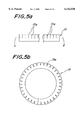
- FIGS. 5a and 5b are a diagrammatic views illustrating a state of forming a weld layer
- FIG. 6 is a perspective view partly shown in section of another embodiment of the air bag according to the invention.
- FIG. 7 is a partly enlarged section view illustrating a state of assembling an inflator into the air bag.
- FIG. 1 sectionally illustrates a main part of an air bag applied to a driver's side of a vehicle in an expanded state.
- This air bag 1 is formed by airtightly joining a front-side laminated film 2 having a circular form facing a driver's seat and a rear-side laminated film 3 facing a side of a vehicle body and having an outer profile size substantially equal to that of the front-side laminated film 2 to each other at their peripheral edge portions.
- a proper sealing method for example, a high-frequency welder sealing method issued and the air bag is provided at a central portion of the back-side laminated film 3 with an opening 5 for the insertion of an inflator 4.
- assembling the air bag 1 and the inflator 4 can be carried out by sandwiching an opened peripheral portion of a base plate 7 attached to a steering shaft and a peripheral edge portion of the opening 5 formed in the back-side laminated film 3 between a flange portion 4a of the inflator 4 provided with a gas jetting portion placed in the opening 5 of the back-side laminated film 3.
- a retainer ring 6 is arranged around the opening 5 and at an inner surface side of the back-side laminated film 3, respectively.
- Each of the front-side and back-side laminated films 2, 3 may be comprised of, for example, a laminate of one elastomer layer 2a (or 3a) and one shape holding layer 2b (or 3b).
- the front-side laminated film 2 when the elastomer layer 2a having a more flexible property is located at the outer surface side of the film, the protection property against the occupant can be enhanced.
- the laminated films 2, 3 are joined to fix the elastomer layers 2a, 3a at the inner surface sides of the films, the joint strength therebetween can advantageously be enhanced.
- the laminated films 2, 3 of the above structure can effectively mitigate the impact shock of the occupant to the air bag under a high energy absorbing ability based on excellent flexibility, stretchability and the like and can prevent the folding of the shape holding layer to prevent the lowering of the fold strength.
- the shape holding layers 2b, 3b are laminated on the entire area of the elastomer layers 2a, 3a and have preferably a thickness of about 5-100 ⁇ m to effectively prevent excessive stretching and local stretching of the elastomer layers 2a, 3a. This effectively prevents the occurrence of breakage, burst and the like of the air bag based on the action of the shape holding layer for properly controlling the deformation and stretching of the elastomer layer.
- each of the laminated films 2, 3 can be carried out by laminating a film-shaped elastomer layer 2a, 3a onto a film-shaped shape holding layer 2b, 3b through an adhesive layer, or by extrusion-coating either one of film-shaped layers onto the other layer, or by simultaneously forming both the layers through multi-layer extrusion.
- each of the laminated films 2, 3 may have a lamination structure of three or more layers. (See FIG. 4.)
- the lamination structure of the laminated film is comprised of two elastomer layers and one shape holding layer interposed therebetween, if two or three laminated films having such a lamination structure are joined at their peripheral edge portions, since the elastomer layer becomes always a joint layer, the joint strength between the films can sufficiently be increased and also the touch feeling of the air bag by the crew in the impact can be improved.
- the lamination structure is comprised of two shape holding layers and one elastomer layer interposed therebetween, the shape holding function can be sufficiently developed even against a large impact force or the like while ensuring excellent energy absorption performance of the air bag.
- lamination structures can be realized by dry lamination interposing an adhesive between the layers, extrusion coating of two layers on both surfaces of a specified layer, extrusion lamination ofjoining plural film layers to each other through molten resin, multi-layer extrusion using a T-die or an inflation die and the like in substantially the same method as described in the aforementioned embodiment.
- thermoplastic elastomer such as urethane, ester or amide
- the joint strength can be increased. Also the impact shock to the occupant in the expansion of the air bag can be effectively mitigated.
- peripheral edge portions between the front-side laminated film 2 and the rear-side laminated film 3 can be carried out by directly sealing both films through a high-frequency welder sealing or the like.
- weld layers 8, 9 each made from a thermoplastic resin material are disposed on opposed surfaces of the front-side and rear-side laminated films 2, 3.
- the weld layers 8, 9 are locally joined to each other at an outward peripheral region in the radial direction of the air bag 1.
- the force in the peeling direction acting on the joint portion is supported not only by the joint portion between the mutual weld layers 8 and 9 but also the joint portions between the weld layer 8 and the laminated film 2 and between the weld layer 9 and the laminated film 3.
- the effect is to effectively disperse the force in the peeling direction, whereby the peel strength in the joint portion between the laminated films 2 and 3 can largely be increased.
- FIG. 2b is a section view illustrating the formation of the above joining structure by means of a high-frequency welder, in which the laminated films 2 and 3 are set to face the shape holding layers 2b and 3b to each other between a pair of upper and lower electrodes 10a, 10b arranged substantially in parallel to each other, while the weld layers 8, 9 are set between the shape holding layers 2b and 3b. Further a peeling member 11. acting to form a non-joining portion over a given region is set between the weld layers 8 and 9 and thereafter both the lectrodes 10a, 10b are closed to each other under pressure. A high frequency voltage is applied between the electrodes 10a, 10b.
- the weld layers 8, 9 are welded to the respective shape holding layers 2b, 3b and bonded to each other at a portion other than the interposed region of the peeling member 11.
- the peeling member 11 made from Teflon film, paper, olefinic resin film or the like is removed after joining or it remains as it is according to circumstance.
- the expansion form of the air bag 1 as shown in FIG. 2a can be produced by the filling of gas.
- the joint structure similar to the above can be produced, as illustrated in FIG. 3a, by arranging a single weld layer 12 having substantially a Y-shaped section, which is formed by previously inserting a peeling member 11a into the weld layer up to a middle position in the widthwise direction thereof, between the laminated films 2 and 3 disposed between the electrodes 10a, 10b.
- the peeling member 11a is made from an olefinic resin, it is possible to previously unite the weld layer 12 and the peeling member 11a with each other by co-extrusion shaping. As a result, the number of elements can effectively be reduced as compared with the case of using two weld layers 8,9 in FIG. 2 and separately arranging two peeling members 11 therebetween as previously mentioned.
- FIG. 3b is a sectional view illustrating a state of applying an internal pressure to the air bag 1 formed by welding the single weld layer 12 to the laminated films 2, 3 under the actuation of the electrodes 10a, 10b.
- the weld layer 12 is unitary one and the joint portion is not existent in the weld layer, a larger force in the peeling direction can be supported by the weld layer 12.
- separate portions 12a, 12b of the weld layer 12 adhered to the laminated films 2, 3 through the peeling member 11a can effectively contribute to support the force in the peeling direction. As a result, a large peel strength can be produced as compared with the joint structure shown in FIG. 2.
- FIG. 4 also schematically shows laminated films having 3 layers, 2a, 2b, 2c and 3a, 3b, and 3c for purposes of illustration.
- Each of the above weld layers may be formed as illustrated in FIG. 5a by forming a plurality of slits 15a in a tape-shaped body 15 having a constant width at given intervals. Then, the tape-shaped body 15 is converted into an annular ring as shown in FIG. 5b through the slits 15a to make its outer diameter substantially equal to an outer diameter of a joint portion between the laminated films 2 and 3, whereby the material treatment can be facilitated and the material yield can be significantly improved.
- the assembling of the inflator 4 onto the air bag 1 is usually carried out by successively passing a plurality of bolts 17 through a retainer ring 6, a rear-side laminated film 3, a base plate 7 and a flange portion 4a of the inflator and then fastening them with reactive nuts 18.
- a retainer ring 6 a rear-side laminated film 3
- a base plate 7 a base plate 7 and a flange portion 4a of the inflator
- one or more reinforcing layers are arranged in at least a portion causing the stress concentration at either inner side or outer side or both sides of the laminated film 3.
- FIG. 7 illustrates reinforcing layers 19, 20 adhered or welded to the inner side or outer side of the laminated film 3.
- each of the reinforcing layers 19, 20 may be made of an elastomer film, a single layer or multilayer laminated film, woven fabric, a single layer or multilayer laminated film adhered to woven fabric, a resin coating of woven fabric and the like.
- the reinforcing layer 19, 20 is made from the elastomer film having a relatively high flexibility, the sealing property in the assembled portion can be improved in addition to providing reinforcement.
- the reinforcing layer 19, 20 is made from the single layer or multilayer laminated film, the reinforcing effect can be increased.
- the reinforcing layer is made from the woven fabric base material, the reinforcing effect can further be improved.
- the material of the reinforcing layer to be used may be same or different.
- the laminated film constituting the air bag is comprised of at least one elastomer layer and at least one shape holding layer, whereby the large energy absorption performance can be produced and the impact shock against the occupant of a vehicle can be effectively mitigated under high flexibility and elongation of the elastomer layer.
- the laminated films are joined to locate the elastomer layers as an inner layer, the joint strength can be effectively increased.
- the shape holding layer laminated over the entire area of the elastomer layer sufficiently prevents excessively stretching deformation of the air bag to remove the problem of stress concentration in the elastomer layer due to the local stretching of the elastomer layer and breaking the air bag due to the excessive stretching of the elastomer layer and the like.
- the shape holding layer can effectively compensate the lack of shock receiving ability when the elastomer layer is freely stretched without restraint.
- the shape holding member can prevent the excessively free stretching of the elastomer layer and hence the breakage of the air bag due to the excessive stretching.
- the joint strength between the laminated films is improved to provide protection to the occupants of the vehicle. Also, the strength and sealing property in the portion surrounding the opening for the inflator can be enhanced and the fold strength of the air bag can be increased.
- the elastomer layer is made from the thermoplastic elastomer such as urethane, ester of amide, the joint strength between the laminated films is further increased and also the resistance to penetration of sharpened object can be enhanced.
- the thermoplastic elastomer such as urethane, ester of amide
- the shape holding layer is made from polycarbonate, polyamide, polyester, polyimide or thermoplastic elastomer having a JIS-A hardness of not less than 95°, the strength of the laminated film itself can largely be increased.
Abstract
An air bag includes a pair of laminated films and an opening for inflator, in which each laminated film is at least one elastomer layer and at least one shape holding layer.
Description
1. Field of the Invention
This invention relates to a light weight air bag for use in the protection of occupants in an automobile from the automobile accident which develops excellent energy absorption performance and is capable of sufficiently preventing accidental breakage or the like due to local concentration of stress, excessive stretching and the like.
2. Description of Related Art
Within this technology, there is known an air bag disclosed, for example, in JP-A-7-291069.
Such an air bag is constructed by adhering a resin film to a portion of an elastomer film to regulate excessive expansion of the air bag made from the elastomer film to enhance the energy absorption performance. In this case, if the occupant moves suddenly into the developed air bag, the stretching of a portion of the elastomer film adhered with the resin film is controlled, while the remaining portion of the elastomer film not adhered with the resin film is stretched to absorb shock through impact.
In the conventional air bag made by locally adhering the resin film to the elastomer film, however, when the shock through impact is absorbed by the stretching deformation of the portion of the elastomer film not adhered with the resin film, a large stress concentrates in a position at a boundary between the adhered portion and the non-adhered portion of the resin film. This may result in a burst resulting from the implosion of the air bag at this position becoming high. Further, the total area of the stretching deformable elastomer film is small, so that the elastomer film is stretched over its stretching limit by the large impact action. Hence there is a possibility of breaking the air bag.
In addition, when the resin film is not adhered to the surface of the elastomer film located opposite to the occupants, the elastomer film is excessively stretched, so that when such a stretched elastomer film simply contacts with a slight protrusive portion of a constructional member located in a side of the vehicle body, these is a possibility of simply breaking the air bag.
It is, therefore, an object of the invention to solve the aforementioned problems of the conventional techniques and provide an air bag having high strength and light weight which can sufficiently absorb impact energy and does not have the potential for burst, breakage and the like even if a large impact force is applied.
The air bag according to the invention is comprised of two or three laminated films formed by joining them at their peripheral edge portions to each other through heat seal, impulse seal, high-frequency welder seal, supersonic seal or the like and has a bag shape as a whole having an opening for the insertion of an inflator, in which the laminated films are at least one elastomer layer and at least one shape-holding layer.
In this air bag, the elastomer layer and the shape holding layer are laminated with each other over their full surfaces irrespective of the portion facing the occupants or the portion opposite to the occupants. Thus the excessive stretching deformation of the air bag in the expansion of the air bag, the collision of the occupant with the expanded air bag and the like is effectively restrained by the action of the shape holding layer. As a result, the energy absorption in collision with the occupant is attained very effectively.
That is, according to the invention, stress is not locally applied to the elastomer layer at a boundary position between the laminated region and the non-laminated region of the shape holding layer. The elastomer layer having a small total area is not locally and excessively stretched and the elastomer layer is not freely stretched without restraining by the shape holding layer. Thus the occurrence of accidental breakage or the like in the air bag is sufficiently prevented independent of the magnitude of impact force input to the air bag.
In the air bag according to the invention, the elastomer layer sufficiently mitigates the impact shock owing to the high flexibility, stretchability and the like inherent to the elastomer layer when the occupant moves suddenly into the air bag. Further, the elastomer layer functions to enhance the joining strength of the mutual joint portion between the laminated films and acts to sufficiently prevent the lowering of strength in the folded portion of the air bag.
Preferably, the laminated films according to the invention have a three-layer laminated structure comprised of two elastomer layers and a shape holding layer interposed therebetween.
More preferably, the elastomer layer is made from a thermoplastic elastomer such as urethane, ester or amide, while the shape holding layer is made from a polycarbonate, a polyamide, a polyimide or a thermoplastic elastomer having a JIS-A-hardness of not less than 95 degrees.
The invention will be described with reference to the accompanying drawings, wherein:
FIG. 1 is a diagrammatically section view of a main part of an embodiment of the air bag according to the invention;
FIG. 2a is a partly enlarged section view illustrating a state of joining laminated films at their peripheral edge portions; and FIG. 2b illustrates the materials positioned prior to lamination;
FIG. 3a illustrates materials positioned prior to lamination in a second embodiment and FIG. 3b is a partly enlarged section view illustrating the state ofjoining laminated films at their peripheral edge potions;
FIG. 4 is a partly enlarged section view illustrating a third embodiment of joining laminated films at their peripheral edge portions;
FIGS. 5a and 5b are a diagrammatic views illustrating a state of forming a weld layer;
FIG. 6 is a perspective view partly shown in section of another embodiment of the air bag according to the invention; and
FIG. 7 is a partly enlarged section view illustrating a state of assembling an inflator into the air bag.
FIG. 1 sectionally illustrates a main part of an air bag applied to a driver's side of a vehicle in an expanded state. This air bag 1 is formed by airtightly joining a front-side laminated film 2 having a circular form facing a driver's seat and a rear-side laminated film 3 facing a side of a vehicle body and having an outer profile size substantially equal to that of the front-side laminated film 2 to each other at their peripheral edge portions. A proper sealing method, for example, a high-frequency welder sealing method issued and the air bag is provided at a central portion of the back-side laminated film 3 with an opening 5 for the insertion of an inflator 4.
In this case, assembling the air bag 1 and the inflator 4 can be carried out by sandwiching an opened peripheral portion of a base plate 7 attached to a steering shaft and a peripheral edge portion of the opening 5 formed in the back-side laminated film 3 between a flange portion 4a of the inflator 4 provided with a gas jetting portion placed in the opening 5 of the back-side laminated film 3. A retainer ring 6 is arranged around the opening 5 and at an inner surface side of the back-side laminated film 3, respectively.
Each of the front-side and back-side laminated films 2, 3 may be comprised of, for example, a laminate of one elastomer layer 2a (or 3a) and one shape holding layer 2b (or 3b). In the front-side laminated film 2, when the elastomer layer 2a having a more flexible property is located at the outer surface side of the film, the protection property against the occupant can be enhanced. When the laminated films 2, 3 are joined to fix the elastomer layers 2a, 3a at the inner surface sides of the films, the joint strength therebetween can advantageously be enhanced.
The laminated films 2, 3 of the above structure can effectively mitigate the impact shock of the occupant to the air bag under a high energy absorbing ability based on excellent flexibility, stretchability and the like and can prevent the folding of the shape holding layer to prevent the lowering of the fold strength.
The shape holding layers 2b, 3b are laminated on the entire area of the elastomer layers 2a, 3a and have preferably a thickness of about 5-100 μm to effectively prevent excessive stretching and local stretching of the elastomer layers 2a, 3a. This effectively prevents the occurrence of breakage, burst and the like of the air bag based on the action of the shape holding layer for properly controlling the deformation and stretching of the elastomer layer.
In the invention, each of the laminated films 2, 3 can be carried out by laminating a film- shaped elastomer layer 2a, 3a onto a film-shaped shape holding layer 2b, 3b through an adhesive layer, or by extrusion-coating either one of film-shaped layers onto the other layer, or by simultaneously forming both the layers through multi-layer extrusion.
Moreover, each of the laminated films 2, 3 may have a lamination structure of three or more layers. (See FIG. 4.) When the lamination structure of the laminated film is comprised of two elastomer layers and one shape holding layer interposed therebetween, if two or three laminated films having such a lamination structure are joined at their peripheral edge portions, since the elastomer layer becomes always a joint layer, the joint strength between the films can sufficiently be increased and also the touch feeling of the air bag by the crew in the impact can be improved. Furthermore, when the lamination structure is comprised of two shape holding layers and one elastomer layer interposed therebetween, the shape holding function can be sufficiently developed even against a large impact force or the like while ensuring excellent energy absorption performance of the air bag.
These lamination structures can be realized by dry lamination interposing an adhesive between the layers, extrusion coating of two layers on both surfaces of a specified layer, extrusion lamination ofjoining plural film layers to each other through molten resin, multi-layer extrusion using a T-die or an inflation die and the like in substantially the same method as described in the aforementioned embodiment.
When a thermoplastic elastomer such as urethane, ester or amide is selected as the elastomer layer, the joint strength can be increased. Also the impact shock to the occupant in the expansion of the air bag can be effectively mitigated.
On the other hand, when polycarbonate, polyamide, polyester, polyimide or a thermoplastic elastomer having JIS-A hardness of not less than 95° is selected as a material of the shape holding layer, the elongation of the elastomer layer exceeding the elongation at break due to the large impact force can be effectively controlled.
Of course, the joining of peripheral edge portions between the front-side laminated film 2 and the rear-side laminated film 3 can be carried out by directly sealing both films through a high-frequency welder sealing or the like. In order to ensure sufficient peel strength against force in peeling direction acting to the joint portion between the laminated films 2 and 3 during rapid expansion of the air bag 1 through the filling of nitrogen gas or the like, the impact of the occupants to the expanded air bag 1, as shown, for example, by a partially enlarged section view in FIG. 2a, it is favorable that weld layers 8, 9 each made from a thermoplastic resin material are disposed on opposed surfaces of the front-side and rear-side laminated films 2, 3. The weld layers 8, 9 are locally joined to each other at an outward peripheral region in the radial direction of the air bag 1.
According to such joining structure between the laminated films 2, 3, the force in the peeling direction acting on the joint portion is supported not only by the joint portion between the mutual weld layers 8 and 9 but also the joint portions between the weld layer 8 and the laminated film 2 and between the weld layer 9 and the laminated film 3. The effect is to effectively disperse the force in the peeling direction, whereby the peel strength in the joint portion between the laminated films 2 and 3 can largely be increased.
FIG. 2b is a section view illustrating the formation of the above joining structure by means of a high-frequency welder, in which the laminated films 2 and 3 are set to face the shape holding layers 2b and 3b to each other between a pair of upper and lower electrodes 10a, 10b arranged substantially in parallel to each other, while the weld layers 8, 9 are set between the shape holding layers 2b and 3b. Further a peeling member 11. acting to form a non-joining portion over a given region is set between the weld layers 8 and 9 and thereafter both the lectrodes 10a, 10b are closed to each other under pressure. A high frequency voltage is applied between the electrodes 10a, 10b.
In this manner, the weld layers 8, 9 are welded to the respective shape holding layers 2b, 3b and bonded to each other at a portion other than the interposed region of the peeling member 11. As a result the peeling member 11 made from Teflon film, paper, olefinic resin film or the like is removed after joining or it remains as it is according to circumstance. The expansion form of the air bag 1 as shown in FIG. 2a can be produced by the filling of gas.
The joint structure similar to the above can be produced, as illustrated in FIG. 3a, by arranging a single weld layer 12 having substantially a Y-shaped section, which is formed by previously inserting a peeling member 11a into the weld layer up to a middle position in the widthwise direction thereof, between the laminated films 2 and 3 disposed between the electrodes 10a, 10b.
For example, when the peeling member 11a is made from an olefinic resin, it is possible to previously unite the weld layer 12 and the peeling member 11a with each other by co-extrusion shaping. As a result, the number of elements can effectively be reduced as compared with the case of using two weld layers 8,9 in FIG. 2 and separately arranging two peeling members 11 therebetween as previously mentioned.
FIG. 3b is a sectional view illustrating a state of applying an internal pressure to the air bag 1 formed by welding the single weld layer 12 to the laminated films 2, 3 under the actuation of the electrodes 10a, 10b. In this case, since the weld layer 12 is unitary one and the joint portion is not existent in the weld layer, a larger force in the peeling direction can be supported by the weld layer 12. Further, separate portions 12a, 12b of the weld layer 12 adhered to the laminated films 2, 3 through the peeling member 11a can effectively contribute to support the force in the peeling direction. As a result, a large peel strength can be produced as compared with the joint structure shown in FIG. 2.
The peel strength can be more effectively improved by arranging two or more weld layers 8, 13 or 9, 14 having stepwise varied lengths viewed in section onto the laminated film 2 or 3 as shown in FIG. 4. FIG. 4 also schematically shows laminated films having 3 layers, 2a, 2b, 2c and 3a, 3b, and 3c for purposes of illustration.
Each of the above weld layers, for example, weld layers 8, 9 may be formed as illustrated in FIG. 5a by forming a plurality of slits 15a in a tape-shaped body 15 having a constant width at given intervals. Then, the tape-shaped body 15 is converted into an annular ring as shown in FIG. 5b through the slits 15a to make its outer diameter substantially equal to an outer diameter of a joint portion between the laminated films 2 and 3, whereby the material treatment can be facilitated and the material yield can be significantly improved.
Although various joint forms on the peripheral edge portions of the front-side and rear-side laminated films 2, 3 are described above, when the air bag 1 is turned over by utilizing a relatively large opening 5 for the insertion of an inflator formed in the rear-side laminated film 3, as shown in FIG. 6, the joint portion between the laminated films 2 and 3 is concealed at the inside of the air bag 1. The occupant of the vehicle can be effectively protected from the joint portion having a relatively high rigidity in the action of the air bag 1.
As shown by an enlarged section in FIG. 7, the assembling of the inflator 4 onto the air bag 1 is usually carried out by successively passing a plurality of bolts 17 through a retainer ring 6, a rear-side laminated film 3, a base plate 7 and a flange portion 4a of the inflator and then fastening them with reactive nuts 18. As a result, it is impossible to avoid the concentration of stress in a portion of the laminated film 3 passing the bolt 17 during the expansion of the air bag 1 or the like.
If the strength obtained by using only the laminated film 3 is not satisfactory, it is favorable that one or more reinforcing layers are arranged in at least a portion causing the stress concentration at either inner side or outer side or both sides of the laminated film 3.
FIG. 7 illustrates reinforcing layers 19, 20 adhered or welded to the inner side or outer side of the laminated film 3. In this case, each of the reinforcing layers 19, 20 may be made of an elastomer film, a single layer or multilayer laminated film, woven fabric, a single layer or multilayer laminated film adhered to woven fabric, a resin coating of woven fabric and the like.
When the reinforcing layer 19, 20 is made from the elastomer film having a relatively high flexibility, the sealing property in the assembled portion can be improved in addition to providing reinforcement. On the other hand, when the reinforcing layer 19, 20 is made from the single layer or multilayer laminated film, the reinforcing effect can be increased. When the reinforcing layer is made from the woven fabric base material, the reinforcing effect can further be improved.
When a plurality of reinforcing layers are arranged on at least one side of the laminated film 3, the material of the reinforcing layer to be used may be same or different.
According to the invention, the laminated film constituting the air bag is comprised of at least one elastomer layer and at least one shape holding layer, whereby the large energy absorption performance can be produced and the impact shock against the occupant of a vehicle can be effectively mitigated under high flexibility and elongation of the elastomer layer. When the laminated films are joined to locate the elastomer layers as an inner layer, the joint strength can be effectively increased.
Further, the shape holding layer laminated over the entire area of the elastomer layer sufficiently prevents excessively stretching deformation of the air bag to remove the problem of stress concentration in the elastomer layer due to the local stretching of the elastomer layer and breaking the air bag due to the excessive stretching of the elastomer layer and the like. Moreover, the shape holding layer can effectively compensate the lack of shock receiving ability when the elastomer layer is freely stretched without restraint. Additionally, the shape holding member can prevent the excessively free stretching of the elastomer layer and hence the breakage of the air bag due to the excessive stretching.
When using plural elastomer layers, the joint strength between the laminated films is improved to provide protection to the occupants of the vehicle. Also, the strength and sealing property in the portion surrounding the opening for the inflator can be enhanced and the fold strength of the air bag can be increased.
On the other hand, when using plural shape holding layers, a high shape-holding function against a large impact force can be developed while maintaining excellent energy absorption performance based on the action of the elastomer layer to sufficiently protect the elastomer layer from the excessive stretching and the like. Also, the strength in the portion surrounding the opening for the inflator can be further increased.
When the elastomer layer is made from the thermoplastic elastomer such as urethane, ester of amide, the joint strength between the laminated films is further increased and also the resistance to penetration of sharpened object can be enhanced.
When the shape holding layer is made from polycarbonate, polyamide, polyester, polyimide or thermoplastic elastomer having a JIS-A hardness of not less than 95°, the strength of the laminated film itself can largely be increased.
Claims (8)
1. An air bag comprising; a pair of laminated films and an opening for the insertion of an inflator, in which each of the laminated films comprise at least one elastomer layer, at least one shape holding layer laminated together thereon over an entire confronting surface of said at least one elastomer layer of each of said pair of laminated films, and a weld layer affixed to said shape holding layer.
2. An air bag according to claim 1, wherein the elastomer layer is made from a thermoplastic elastomer selected from urethane, ester and amide.
3. An air bag according to claim 1, wherein the shape holding layer is made from a polycarbonate, a polyamide, a polyester, a polyimide or a thermoplastic elastomer having a JIS-A hardness of not less than 95°.
4. An air bag according to claim 1, wherein said weld layer is a thermoplastic material.
5. An air bag according to claim 1, further comprising a reinforcing layer affixed to a laminated film at an end portion of said film.
6. An air bag according to claim 5, wherein said reinforcing layer comprises an elastomer film.
7. An air bag comprising; a pair of laminated films and an opening for the insertion of an inflator, in which each of the laminated films comprises two elastomer layers and at least one shape holding layer, and wherein each laminated film comprises three layers composed of said two elastomer layers and said at least one shape holding layer interposed therebetween, with each of said elastomer layers laminated over an entire confronting surface of said at least one shape holding layer.
8. An air bag comprising; a pair of laminated films and an opening for the insertion of inflator, in which each of the laminated films comprises at least one elastomer layer and two shape holding layers and wherein the laminated film comprises three layers composed of said two shape holding layers and said at least one elastomer layer interposed therebetween, with each of said shape holding layer laminated over an entire confronting surface of said at least one elastomer layer.
Applications Claiming Priority (2)
| Application Number | Priority Date | Filing Date | Title |
|---|---|---|---|
| JP8-212562 | 1996-08-12 | ||
| JP21256296A JPH1059104A (en) | 1996-08-12 | 1996-08-12 | Air bag |
Publications (1)
| Publication Number | Publication Date |
|---|---|
| US6142520A true US6142520A (en) | 2000-11-07 |
Family
ID=16624762
Family Applications (1)
| Application Number | Title | Priority Date | Filing Date |
|---|---|---|---|
| US08/907,864 Expired - Fee Related US6142520A (en) | 1996-08-12 | 1997-08-11 | Air bag |
Country Status (4)
| Country | Link |
|---|---|
| US (1) | US6142520A (en) |
| JP (1) | JPH1059104A (en) |
| DE (1) | DE19734899A1 (en) |
| GB (1) | GB2316043A (en) |
Cited By (25)
| Publication number | Priority date | Publication date | Assignee | Title |
|---|---|---|---|---|
| WO2001051318A1 (en) * | 2000-01-07 | 2001-07-19 | Milliken & Company | Twelve-sided polygon-shaped air bag |
| US6431587B1 (en) * | 1999-11-02 | 2002-08-13 | Trw Inc. | Inflatable side curtain |
| US6454301B1 (en) * | 1995-09-22 | 2002-09-24 | Joseph Rychter | Inflatable airbag with pre-determined three-dimensional shape |
| US6695346B1 (en) | 1999-04-23 | 2004-02-24 | Milliken & Company | Polygon-shaped air bag with lapping seam area |
| US20040245749A1 (en) * | 2003-05-22 | 2004-12-09 | Aerazur S.A.S.U. | Sealing device for the interface between an airbag and a gas generator |
| US20060192372A1 (en) * | 2005-02-28 | 2006-08-31 | Takata Restraint Systems, Inc. | Coated sewing thread for airbag and method of sealing an airbag |
| US20060202452A1 (en) * | 1994-05-23 | 2006-09-14 | Automotive Technologies International, Inc. | Side curtain and multi-compartment vehicular airbags |
| US7232001B2 (en) | 2004-08-24 | 2007-06-19 | Sam Hakki | Collision air bag and flotation system |
| US20080243342A1 (en) * | 1995-12-12 | 2008-10-02 | Automotive Technologies International, Inc. | Side Curtain Airbag With Inflator At End |
| US20090224515A1 (en) * | 2007-05-21 | 2009-09-10 | Breed David S | Film Airbags |
| US20100078919A1 (en) * | 2008-09-30 | 2010-04-01 | Toyoda Gosei Co., Ltd. | Airbag |
| US20110042929A1 (en) * | 2007-05-21 | 2011-02-24 | Automotive Technologies International, Inc. | Film airbags |
| US20110109064A1 (en) * | 2008-04-11 | 2011-05-12 | Michael James Best | Inflatable bolster |
| US20110198827A1 (en) * | 2009-12-24 | 2011-08-18 | Roychoudhury Raj S | Passenger side active knee bolster |
| US20120291948A1 (en) * | 2011-05-17 | 2012-11-22 | The Boeing Company | Thermoplastic welding apparatus and method |
| US8474861B1 (en) | 2012-03-28 | 2013-07-02 | Faurecia Interior Systems, Inc. | Interior panels having integrated airbag deployment doors for motor vehicles and methods for making the same |
| US8491008B2 (en) | 2010-05-05 | 2013-07-23 | Salflex Polymers Ltd. | Injection molded inflatable active bolster |
| US8544880B2 (en) | 2005-06-03 | 2013-10-01 | Salflex Polymers Ltd. | Active bolster |
| US8579325B2 (en) | 2010-11-09 | 2013-11-12 | Salflex Polymers Ltd. | Active bolster |
| US9010800B1 (en) | 2014-05-28 | 2015-04-21 | Faurecia Interior Systems, Inc. | Interior panels having integrated airbag doors for motor vehicles and methods for making the same |
| US9254808B2 (en) | 2011-02-07 | 2016-02-09 | Salflex Polymers Limited | Active bolster assembly |
| US20180224027A1 (en) * | 2015-07-27 | 2018-08-09 | Radius Systems Limited | Flexible pipe connector and method of using the same |
| US10195791B1 (en) * | 2016-03-10 | 2019-02-05 | Air Cruisers Company, LLC | Welded reinforcement for inflatable devices |
| US10259419B2 (en) * | 2014-01-09 | 2019-04-16 | Joyson Safety Systems Germany Gmbh | Gas bag arrangement and method for manufacturing a gas bag arrangement |
| US20200316487A1 (en) * | 2019-04-02 | 2020-10-08 | Hunter Products Pty Ltd | Toy |
Families Citing this family (13)
| Publication number | Priority date | Publication date | Assignee | Title |
|---|---|---|---|---|
| US5863068A (en) * | 1994-05-23 | 1999-01-26 | Automotive Technologies International, Inc. | Plastic film airbag |
| US6149194A (en) * | 1994-05-23 | 2000-11-21 | Automotive Technologies International, Inc. | Plastic film airbag |
| US6250668B1 (en) | 1994-05-23 | 2001-06-26 | Automotive Technologies International, Inc. | Tubular airbag, method of making the same and occupant protection system including the same |
| JP3726518B2 (en) * | 1998-11-18 | 2005-12-14 | タカタ株式会社 | Airbag |
| JP3738589B2 (en) * | 1999-02-09 | 2006-01-25 | トヨタ紡織株式会社 | Bag-woven airbag and method for manufacturing the same |
| US6364356B1 (en) * | 1999-09-24 | 2002-04-02 | Milliken & Company | Airbag cushion comprising sewn reinforcement seams |
| GB2372237B (en) * | 2001-02-16 | 2004-07-28 | Autoliv Dev | Improvements in or relating to an air-bag |
| DE10153243B4 (en) * | 2001-10-31 | 2008-11-06 | Volker Friedrich | Air Bag (Air Bag) |
| JP2009090905A (en) * | 2007-10-11 | 2009-04-30 | Gsk Intek Co Ltd | Safety airbag cloth product |
| EP2689974B1 (en) * | 2012-07-25 | 2019-09-11 | Autoliv Development AB | Method for producing a vehicle air-bag |
| DE102014220211B4 (en) * | 2014-10-07 | 2019-12-05 | Conti Temic Microelectronic Gmbh | Method and device for joining two layers of material by means of high frequency welding |
| ITUA20161999A1 (en) * | 2016-03-24 | 2017-09-24 | Dainese Spa | PROTECTION DEVICE |
| DE202016002894U1 (en) | 2016-05-03 | 2016-06-08 | Nick Eckert | Device for producing a film airbag |
Citations (11)
| Publication number | Priority date | Publication date | Assignee | Title |
|---|---|---|---|---|
| JPH02114035A (en) * | 1988-10-24 | 1990-04-26 | Toray Ind Inc | Base cloth for air bag of car |
| EP0380699A1 (en) * | 1988-08-03 | 1990-08-08 | Asahi Kasei Kogyo Kabushiki Kaisha | Air bag |
| JPH02237837A (en) * | 1989-08-29 | 1990-09-20 | Takata Kk | Air bag |
| JPH03208746A (en) * | 1990-01-09 | 1991-09-11 | Toray Ind Inc | Air bag |
| US5100168A (en) * | 1990-04-06 | 1992-03-31 | Toyoda Gosei Co., Ltd. | Air bag for vehicles |
| JPH04201649A (en) * | 1990-11-29 | 1992-07-22 | Toray Ind Inc | Air bag |
| GB2252983A (en) * | 1990-12-27 | 1992-08-26 | Bridgestone Corp | Air bag |
| JPH04325342A (en) * | 1991-04-23 | 1992-11-13 | Toray Ind Inc | Sheet for air bag |
| JPH07291069A (en) * | 1994-04-26 | 1995-11-07 | Takata Kk | Air bag |
| DE19513297A1 (en) * | 1994-05-02 | 1995-11-09 | Edward B Palm | Inflatable restraint and method of making the same |
| EP0702106A1 (en) * | 1994-09-16 | 1996-03-20 | Takata Corporation | Base fabric for air bags and method for the preparation thereof |
-
1996
- 1996-08-12 JP JP21256296A patent/JPH1059104A/en active Pending
-
1997
- 1997-08-11 US US08/907,864 patent/US6142520A/en not_active Expired - Fee Related
- 1997-08-12 DE DE1997134899 patent/DE19734899A1/en not_active Ceased
- 1997-08-12 GB GB9717102A patent/GB2316043A/en not_active Withdrawn
Patent Citations (12)
| Publication number | Priority date | Publication date | Assignee | Title |
|---|---|---|---|---|
| EP0380699A1 (en) * | 1988-08-03 | 1990-08-08 | Asahi Kasei Kogyo Kabushiki Kaisha | Air bag |
| JPH02114035A (en) * | 1988-10-24 | 1990-04-26 | Toray Ind Inc | Base cloth for air bag of car |
| JPH02237837A (en) * | 1989-08-29 | 1990-09-20 | Takata Kk | Air bag |
| JPH03208746A (en) * | 1990-01-09 | 1991-09-11 | Toray Ind Inc | Air bag |
| US5100168A (en) * | 1990-04-06 | 1992-03-31 | Toyoda Gosei Co., Ltd. | Air bag for vehicles |
| JPH04201649A (en) * | 1990-11-29 | 1992-07-22 | Toray Ind Inc | Air bag |
| GB2252983A (en) * | 1990-12-27 | 1992-08-26 | Bridgestone Corp | Air bag |
| JPH04325342A (en) * | 1991-04-23 | 1992-11-13 | Toray Ind Inc | Sheet for air bag |
| JPH07291069A (en) * | 1994-04-26 | 1995-11-07 | Takata Kk | Air bag |
| US5524926A (en) * | 1994-04-26 | 1996-06-11 | Takata Corporation | Air bag for protecting an occupant |
| DE19513297A1 (en) * | 1994-05-02 | 1995-11-09 | Edward B Palm | Inflatable restraint and method of making the same |
| EP0702106A1 (en) * | 1994-09-16 | 1996-03-20 | Takata Corporation | Base fabric for air bags and method for the preparation thereof |
Cited By (47)
| Publication number | Priority date | Publication date | Assignee | Title |
|---|---|---|---|---|
| US20090039625A1 (en) * | 1994-05-23 | 2009-02-12 | Automotive Technologies International, Inc. | Vehicular Occupant Protection Method Using Airbags |
| US20060202452A1 (en) * | 1994-05-23 | 2006-09-14 | Automotive Technologies International, Inc. | Side curtain and multi-compartment vehicular airbags |
| US6454301B1 (en) * | 1995-09-22 | 2002-09-24 | Joseph Rychter | Inflatable airbag with pre-determined three-dimensional shape |
| US20080243342A1 (en) * | 1995-12-12 | 2008-10-02 | Automotive Technologies International, Inc. | Side Curtain Airbag With Inflator At End |
| US9043093B2 (en) | 1995-12-12 | 2015-05-26 | American Vehicular Sciences Llc | Single side curtain airbag for vehicles |
| US9022417B2 (en) | 1995-12-12 | 2015-05-05 | American Vehicular Sciences Llc | Single side curtain airbag for vehicles |
| US6695346B1 (en) | 1999-04-23 | 2004-02-24 | Milliken & Company | Polygon-shaped air bag with lapping seam area |
| US6431587B1 (en) * | 1999-11-02 | 2002-08-13 | Trw Inc. | Inflatable side curtain |
| US6685215B2 (en) * | 2000-01-07 | 2004-02-03 | Milliken & Company | Twelve-sided polygon-shaped air bag |
| WO2001051318A1 (en) * | 2000-01-07 | 2001-07-19 | Milliken & Company | Twelve-sided polygon-shaped air bag |
| US20040245749A1 (en) * | 2003-05-22 | 2004-12-09 | Aerazur S.A.S.U. | Sealing device for the interface between an airbag and a gas generator |
| US7232001B2 (en) | 2004-08-24 | 2007-06-19 | Sam Hakki | Collision air bag and flotation system |
| US7882921B2 (en) | 2004-08-24 | 2011-02-08 | Sam Hakki | Collision air bag and flotation system |
| US20060192372A1 (en) * | 2005-02-28 | 2006-08-31 | Takata Restraint Systems, Inc. | Coated sewing thread for airbag and method of sealing an airbag |
| US10315608B2 (en) | 2005-06-03 | 2019-06-11 | Abc Technologies Inc. | Active bolster |
| US9731675B2 (en) | 2005-06-03 | 2017-08-15 | Abc Group Inc. | Active bolster |
| US9085275B2 (en) | 2005-06-03 | 2015-07-21 | Salflex Polymers Ltd. | Active bolster |
| US8544880B2 (en) | 2005-06-03 | 2013-10-01 | Salflex Polymers Ltd. | Active bolster |
| US8801032B2 (en) | 2005-06-03 | 2014-08-12 | Salflex Polymers Ltd. | Active bolster |
| US8827307B2 (en) | 2005-11-17 | 2014-09-09 | Salflex Polymers Ltd. | Inflatable bolster |
| US20110042929A1 (en) * | 2007-05-21 | 2011-02-24 | Automotive Technologies International, Inc. | Film airbags |
| USRE46533E1 (en) | 2007-05-21 | 2017-09-05 | Automotive Technologies International, Inc. | Film airbags |
| US7820566B2 (en) | 2007-05-21 | 2010-10-26 | Automotive Technologies International, Inc. | Film airbags |
| US20090224515A1 (en) * | 2007-05-21 | 2009-09-10 | Breed David S | Film Airbags |
| US8822357B2 (en) | 2007-05-21 | 2014-09-02 | Automotive Technologies International, Inc. | Film airbags made from ribbons |
| US8388020B2 (en) * | 2008-04-11 | 2013-03-05 | Salflex Polymers Ltd. | Inflatable multilayer bolster and method of manufacture |
| US8544876B2 (en) | 2008-04-11 | 2013-10-01 | Salflex Polymers Ltd. | Inflatable bolster |
| US20110109064A1 (en) * | 2008-04-11 | 2011-05-12 | Michael James Best | Inflatable bolster |
| US20110115201A1 (en) * | 2008-04-11 | 2011-05-19 | Michael James Best | Inflatable bolster |
| US20110123739A1 (en) * | 2008-04-11 | 2011-05-26 | Rimas Ciplijauskas | Inflatable multilayer bolster and method of manufacture |
| US8348305B2 (en) * | 2008-09-30 | 2013-01-08 | Toyoda Gosei Co., Ltd. | Airbag |
| US20100078919A1 (en) * | 2008-09-30 | 2010-04-01 | Toyoda Gosei Co., Ltd. | Airbag |
| US20110198827A1 (en) * | 2009-12-24 | 2011-08-18 | Roychoudhury Raj S | Passenger side active knee bolster |
| US8459689B2 (en) | 2009-12-24 | 2013-06-11 | Salflex Polymers Ltd. | Passenger side active knee bolster |
| US8491008B2 (en) | 2010-05-05 | 2013-07-23 | Salflex Polymers Ltd. | Injection molded inflatable active bolster |
| US8579325B2 (en) | 2010-11-09 | 2013-11-12 | Salflex Polymers Ltd. | Active bolster |
| US8931803B2 (en) | 2010-11-09 | 2015-01-13 | Salflex Polymers Ltd. | Active bolster |
| US9254808B2 (en) | 2011-02-07 | 2016-02-09 | Salflex Polymers Limited | Active bolster assembly |
| US9586362B2 (en) * | 2011-05-17 | 2017-03-07 | The Boeing Company | Thermoplastic welding apparatus and method |
| US20120291948A1 (en) * | 2011-05-17 | 2012-11-22 | The Boeing Company | Thermoplastic welding apparatus and method |
| US11077625B2 (en) | 2011-05-17 | 2021-08-03 | The Boeing Company | Thermoplastic welding apparatus and related methods |
| US8474861B1 (en) | 2012-03-28 | 2013-07-02 | Faurecia Interior Systems, Inc. | Interior panels having integrated airbag deployment doors for motor vehicles and methods for making the same |
| US10259419B2 (en) * | 2014-01-09 | 2019-04-16 | Joyson Safety Systems Germany Gmbh | Gas bag arrangement and method for manufacturing a gas bag arrangement |
| US9010800B1 (en) | 2014-05-28 | 2015-04-21 | Faurecia Interior Systems, Inc. | Interior panels having integrated airbag doors for motor vehicles and methods for making the same |
| US20180224027A1 (en) * | 2015-07-27 | 2018-08-09 | Radius Systems Limited | Flexible pipe connector and method of using the same |
| US10195791B1 (en) * | 2016-03-10 | 2019-02-05 | Air Cruisers Company, LLC | Welded reinforcement for inflatable devices |
| US20200316487A1 (en) * | 2019-04-02 | 2020-10-08 | Hunter Products Pty Ltd | Toy |
Also Published As
| Publication number | Publication date |
|---|---|
| GB2316043A (en) | 1998-02-18 |
| JPH1059104A (en) | 1998-03-03 |
| DE19734899A1 (en) | 1998-02-19 |
| GB9717102D0 (en) | 1997-10-15 |
Similar Documents
| Publication | Publication Date | Title |
|---|---|---|
| US6142520A (en) | Air bag | |
| US5653464A (en) | Airbag system with self shaping airbag | |
| US5909895A (en) | Thermoplastic resin film air bag | |
| EP1161361B1 (en) | Inflatable cushion | |
| US6254122B1 (en) | Reinforced trim cover for a vehicle seat assembly with a tear line for airbag deployment | |
| US6883826B2 (en) | Cushion for protection of a vehicle occupant's head | |
| US5863068A (en) | Plastic film airbag | |
| US5630620A (en) | Reinforced thermoplastic resin film air bag | |
| EP0962363B1 (en) | Airbag | |
| US8167333B2 (en) | Secured force concentrator in a vehicular bolster for airbag retention and deployment | |
| US8376401B2 (en) | Airbag | |
| FR2645093A1 (en) | INFLATABLE BAG FOR PROTECTION AGAINST COLLISIONS | |
| JPH08207680A (en) | Expansible control cushion | |
| US20060205302A1 (en) | Film lined airbag | |
| JP4969112B2 (en) | Airbag | |
| JP4089918B2 (en) | Inflator bag for occupant restraint device, mounting structure thereof, and occupant waist restraint device | |
| US6695346B1 (en) | Polygon-shaped air bag with lapping seam area | |
| US5997035A (en) | Resin air bag | |
| JP3665941B2 (en) | Airbag | |
| JPH02162134A (en) | Air bag for air bag installation | |
| JP3937296B2 (en) | Airbag door opening structure | |
| JPH09119066A (en) | Air bag | |
| JPH1076908A (en) | Air bag | |
| JP2005170206A (en) | Air bag device | |
| JPH1035383A (en) | Cutting method for air bag, and air bag |
Legal Events
| Date | Code | Title | Description |
|---|---|---|---|
| AS | Assignment |
Owner name: BRIDGESTONE CORPORATION, JAPAN Free format text: ASSIGNMENT OF ASSIGNORS INTEREST;ASSIGNORS:IINO, YASUHIRO;TERAZAWA, TOMOZANE;MATSUSHIMA, YOSUKE;REEL/FRAME:008986/0187 Effective date: 19971014 |
|
| FEPP | Fee payment procedure |
Free format text: PAYOR NUMBER ASSIGNED (ORIGINAL EVENT CODE: ASPN); ENTITY STATUS OF PATENT OWNER: LARGE ENTITY |
|
| FPAY | Fee payment |
Year of fee payment: 4 |
|
| REMI | Maintenance fee reminder mailed | ||
| LAPS | Lapse for failure to pay maintenance fees | ||
| STCH | Information on status: patent discontinuation |
Free format text: PATENT EXPIRED DUE TO NONPAYMENT OF MAINTENANCE FEES UNDER 37 CFR 1.362 |
|
| FP | Lapsed due to failure to pay maintenance fee |
Effective date: 20081107 |