US6121730A - Metal hydrides lamp and fill for the same - Google Patents
Metal hydrides lamp and fill for the same Download PDFInfo
- Publication number
- US6121730A US6121730A US09/090,863 US9086398A US6121730A US 6121730 A US6121730 A US 6121730A US 9086398 A US9086398 A US 9086398A US 6121730 A US6121730 A US 6121730A
- Authority
- US
- United States
- Prior art keywords
- lamp
- fill
- metal
- chamber
- hydrogen
- Prior art date
- Legal status (The legal status is an assumption and is not a legal conclusion. Google has not performed a legal analysis and makes no representation as to the accuracy of the status listed.)
- Expired - Lifetime
Links
Images


Classifications
-
- H—ELECTRICITY
- H01—ELECTRIC ELEMENTS
- H01J—ELECTRIC DISCHARGE TUBES OR DISCHARGE LAMPS
- H01J61/00—Gas-discharge or vapour-discharge lamps
- H01J61/02—Details
- H01J61/12—Selection of substances for gas fillings; Specified operating pressure or temperature
-
- H—ELECTRICITY
- H01—ELECTRIC ELEMENTS
- H01J—ELECTRIC DISCHARGE TUBES OR DISCHARGE LAMPS
- H01J61/00—Gas-discharge or vapour-discharge lamps
- H01J61/68—Lamps in which the main discharge is between parts of a current-carrying guide, e.g. halo lamp
Definitions
- the present invention relates to a metal hydrides discharge lamp. More specifically, the present invention is directed towards a discharge lamp having a chamber filled with metal, hydrogen or deuterium, and a buffer gas.
- High intensity discharge lamps such as high pressure sodium lamps and metal halide lamps, are well known. These lamps have a light transmissive, hermetically sealed, discharge chamber or tube; the chamber generally has the shape of a pillbox or slightly flatted sphere.
- the material inside the chamber includes a suitable inert buffer gas and one or more ionizable metals or metal halides.
- Electrodeless lamp In a typical lamp, an electric potential is developed between two electrodes in the lamp chamber, which provides energy to the fill in the chamber.
- an electric potential is developed between two electrodes in the lamp chamber, which provides energy to the fill in the chamber.
- an external capacitive or inductive element such as a coil
- An electromagnetic field generated by passing electricity through the external element provides energy to the fill in the chamber to promote light emission from the fill.
- a fill adapted to produce light when energy is imparted thereto.
- the fill includes at least one metal, at least one of hydrogen and deuterium, and at least one buffer gas having a density less than or equal to 1.0 ⁇ 10 19 atoms/cm 3 .
- the at least one metal includes an alkaline metal, preferably at least one of magnesium, calcium, barium, and strontium.
- the at least one metal additionally includes at least one of sodium, lithium, indium, cadmium, and mercury.
- the at least one buffer gas is at least one noble gas, preferably at least one of xenon and argon.
- a ratio of a pressure of the at least one of hydrogen and deuterium to a total pressure of the at least one of hydrogen and deuterium and the at least one buffer gas is between 5-20% at 25° C.
- the at least one metal is present in an amount sufficient to create a vapor density in the fill between 10 14 and 10 16 atoms/cm 3 when vaporized, preferably approximately 10 15 atoms/cm 3 .
- a lamp including a sealed chamber. At least a portion of the chamber has a light transmissive surface.
- a fill is provided in the chamber.
- the fill includes at least one metal, at least one of hydrogen and deuterium, and at least one buffer gas having a density of less than or equal to 1.0 ⁇ 10 19 atoms/cm 3 .
- At least a portion of the chamber is made of sapphire, ceramic, or quartz and a protective layer which isolates the at least one metal from the quartz.
- a device transmits energy to the fill.
- a power source connected to the device provides steady state power or near steady state power.
- the device is a coil in proximity to the chamber, which generates an electromagnetic field sufficient to facilitate discharge of the fill when oscillating electricity is passed through the coil.
- the coil is preferably made of one of at least one of silver, copper, and aluminum.
- the device includes first and second electrodes mounted in the chamber.
- the at least one metal includes an alkaline metal, preferably at least one of magnesium, calcium, barium, and strontium.
- a ratio of a pressure of the at least one of hydrogen and deuterium to the total gas pressure in the chamber is between 5-20% at 25° C.
- the at least one metal is present in an amount sufficient to create a vapor density of between 10 14 and 10 16 atoms/cm 3 in the chamber when the metal is vaporized, preferably approximately 10 15 atoms/cm 3 when the at least one metal is vaporized.
- a total pressure in the chamber at approximately 25° C. is approximately 2.0 Torr, and a pressure of the at least one of hydrogen and deuterium is approximately 0.2 Torr.
- FIG. 1 is a schematic illustration of a preferred embodiment of the invention
- FIG. 2 is a schematic illustration of another embodiment of the invention.
- FIG. 3 is a diagram of the lower energy states of an MgH molecule
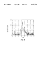
- FIG. 4A is a logarithmic graph of the intensity of light at various frequencies produced by the lamp.
- the bands at 480, 520, and 560 nm are primarily due to an MgH molecule moving from an excited state to a lower electronic state;
- FIG. 4B is a graph of the intensity of light at various frequencies around 520 nm produced by an MgH lamp
- FIG. 5 is a logarithmic graph of the intensity of light at various frequencies produced by an MgD lamp.
- the bands at 480, 520, and 560 nm are primarily due to an MgD molecule moving from an excited state to a lower electronic state;
- FIG. 6 is a graph of the efficacy produced by different combinations of hydrogen pressure to total pressure in the lamp fill.
- the present invention is based upon the observation that metal hydrides (molecules of metal and hydrogen) provide an excellent material for a lamp fill. Many metal hydrides will emit light within the visible spectrum. The hydrides have a relatively high disassociation energy (e.g., 2.4 eV for magnesium hydride), and are thus quite stable. Further, hydrides tend to remain at the ground and the strongly rotating A 2 ⁇ excited state, such that there is little waste heat energy produced as a result of higher energy levels. Hydrides also have many rotational levels, which minimize radiation trapping of emitted light. All of these factors contribute to the efficacy of fills utilizing hydrides.
- disassociation energy e.g., 2.4 eV for magnesium hydride
- FIG. 1 A preferred embodiment of the present invention in conjunction with an electrodeless lamp is shown in FIG. 1.
- the lamp includes a light transmissive discharge chamber 1, an inductive coil 2, and a power supply 3.
- the chamber fill includes solid magnesium (the metal), hydrogen, and argon (the buffer gas).
- Power supply 3 preferably provides an AC current of 13.56 MHZ, and between 10 W and 150 W of input power.
- a water or air cooler may be provided to cool coil 2 to counteract the effect of temperature changes in chamber 1. In this case, thermal insulation between coil 2 and chamber 1 is needed.
- chamber 1 has a 22 mm inner diameter and is 25 mm long.
- the fill includes approximately 1 mg of solid magnesium.
- the amount of hydrogen gas in chamber 1 creates a pressure of 0.2 Torr, and the amount of argon creates a pressure of 1.8 Torr.
- gaseous magnesium has a lower ionization energy than the argon (approximately 7.6 eV for magnesium compared with 13.4 eV for H, 15.4 eV for H 2 , and 15.8 eV for argon), the magnesium becomes the main source of electrons.
- the magnesium atoms combine with the hydrogen (H 2 ) gas and additional energy from other electrons to produce excited A state magnesium hydride (MgH*).
- the excited A state magnesium hydride molecules spontaneously release their excitation to reach the lower energy X state. The energy is released as visible light.
- the energy diagram for magnesium hydride is shown in FIG. 3.
- the solid curves represent the resonance energy levels for a magnesium hydride molecule.
- Vibrational energy also produces light in adjacent wavelength bands, which form peaks at approximately 480 nm and 560 nm (best seen in FIG. 4A).
- movement from the rotational levels produces light with varying wavelengths, which tends to widen the overall wavelength bands of the emitted light in the peak areas.
- FIGS. 4A and 4B show logarithmic and absolute values of the relative intensity of the emitted light, which is green in color for a fill containing magnesium hydride.
- the resulting energy efficiency is approximately 10.4%.
- the lamp spectrum peaks at the peak of the eye sensitivity, which represents about 90 lm/W.
- FIG. 6 shows data for the relative efficacy resulting from fills with varying ratios of hydrogen pressure to total pressure (from the hydrogen and buffer gas in the fill) at 25° C.
- a ratio of 0.2 Torr hydrogen to a total pressure of 2.0 Torr i.e., 1.8 Torr argon
- ratios of hydrogen pressure to total pressure in the range of 5-20% produced similar results, although other higher or slightly lower ratios may also be effective.
- the pressure of the buffer gas should be below 300 Torr (approximately 1.0 ⁇ 10 19 atoms/cm 3 ), and more specifically less than 100 Torr (approximately 3 ⁇ 10 18 atoms/cm 3 ).
- deuterium (D 2 ) gas is used in the fill rather than hydrogen.
- D 2 deuterium
- the resultant visible energy produced by both the principal movement between energy states in combination with vibrational and rotational energy, has a relative intensity shown in FIG. 5.
- the efficacy for this fill is similar to a hydrides lamp of corresponding pressures, although there may be some effect on efficacy due to different thermal losses.
- a combination of 1 mg magnesium, 0.4 Torr deuterium and a total pressure of 2 Torr produced an energy efficiency of approximately 12.5%.
- magnesium is used as the metal in the fill.
- other metals preferably alkaline metals, may be used.
- calcium, barium, and strontium, all of which produce red and blue light could be used, either individually or in various combinations (including combinations with magnesium).
- Color characteristics of the light may further be adjusted by adding solid sodium (orange light), lithium (red light), or mercury, indium or cadmium (blue light).
- the amount of solid metal should be sufficient to create a vapor density of between 10 14 and 10 16 atoms/cm 3 , and preferably approximately 10 15 atoms/cm 3 . If too little metal is used (and the resultant vapor density too low), the probability of sufficient collisions between the metal atoms and the hydrogen is too low to produce any appreciable light. If the metal density is to high, the efficacy decreases due to decreasing electron temperature (too high electron density).
- the fill may include metal(s), a buffer gas, hydrogen and deuterium.
- the fill may include metal(s), a buffer gas, hydrogen and deuterium.
- the total amount of hydrogen and deuterium should be at least 10 14 atoms/cm 3 .
- the chamber 1 above is preferably made of Al 2 O 3 (sapphire) to prevent degradation from the metal.
- any material that does not react with the metal can be used.
- ceramic or ceramic coated glass or quartz such as Y 2 O 3 , MgO, ZrO 2 , ThO 2 , BeO, MgAlO 4 , AL 6 Si 2 O 13 , Al 10 Y 6 O 24 or AlN, or a combination of these materials, may be used.
- a ceramic material such as Si 3 N 4 or BN, may also be used in conjunction with a protective layer that prevents the metal(s) in the fill from degrading the quartz; chemical vapor deposition using a gas mixture of SiH 4 --Ar and NH 3 can be used to form such a protective layer.
- coil 2 is preferable made of silver.
- copper protected from oxidation by encapsulation in a lamp envelope or a protective insulating layer could be used. Cooled copper or aluminum, air or water cooled either through a separate cooling system or the coil through which the coolant is passed, may also be used. A silver coating encapsulated on copper to prevent oxidation thereof is also acceptable.
- a third embodiment of the present invention as utilized in a standard electrode lamp is shown in FIG. 2.
- a light transmissive chamber 11 has first and second electrodes 12a and 12b therein, which are connected to a power supply 13. Both electrodes 12a and 12b are preferably made of tungsten.
- the size of chamber 11 in this embodiment, which is dependent upon the input power (in this case 150W), is 65 mm between electrodes and 5 mm in diameter.
- the fill inside chamber 11 includes 1 mg of magnesium, 8 Torr of hydrogen gas, and 100 Torr of xenon as the buffer gas. When sufficient potential is established between electrodes 12a and 12b by power source 13, the xenon gas will provide electrons at starting. The production of MgH and visible light is the same as discussed in the previous embodiments.
- the preferred buffer gas for the fill is argon or xenon
- any appropriate buffer gas which provides electrons, and particularly any noble gas may be used.
- the ratios of hydrogen/deuterium preferably remains in the 5-20% total pressure range regardless of the buffer gas selected, although values outside this range may prove acceptable based upon the various combinations of materials in the fill provided that the molecules of metal, hydrogen, and deuterium are the source of the majority of emitted light.
- power supply 3 is set to 13.56 MHZ to facilitate fill discharge in the preferred embodiment.
- any appropriate frequency which generates an electric field in chamber 1 which induces discharge may be used.
- the present invention is not limited to electrode and electrodeless lamps. Any environment which imparts energy into the fill to facilitate the chemical reactions described herein also fall within the scope and spirit of the invention.
- One such example is a lamp which transmits microwave energy into the chamber.
- chamber 1 and 11 are preferably completely light transmissive, the invention is not so limited; and chambers having only a portion thereof which is light transmissive may be used.
- chambers 1 and 11 are not limited to the dimensions described herein. Any appropriate size may be used provided that the fill components are within the parameters discussed herein.
Abstract
Description
Mg+H.sub.2 MgH*+H(electron assisted)
MgH*→MgH+energy(radiation)
Mg+D.sub.2 →MgD*+D(electron assisted)
MgD*→MgD+energy(radiation)
Claims (24)
Priority Applications (1)
| Application Number | Priority Date | Filing Date | Title |
|---|---|---|---|
| US09/090,863 US6121730A (en) | 1998-06-05 | 1998-06-05 | Metal hydrides lamp and fill for the same |
Applications Claiming Priority (1)
| Application Number | Priority Date | Filing Date | Title |
|---|---|---|---|
| US09/090,863 US6121730A (en) | 1998-06-05 | 1998-06-05 | Metal hydrides lamp and fill for the same |
Publications (1)
| Publication Number | Publication Date |
|---|---|
| US6121730A true US6121730A (en) | 2000-09-19 |
Family
ID=22224686
Family Applications (1)
| Application Number | Title | Priority Date | Filing Date |
|---|---|---|---|
| US09/090,863 Expired - Lifetime US6121730A (en) | 1998-06-05 | 1998-06-05 | Metal hydrides lamp and fill for the same |
Country Status (1)
| Country | Link |
|---|---|
| US (1) | US6121730A (en) |
Cited By (5)
| Publication number | Priority date | Publication date | Assignee | Title |
|---|---|---|---|---|
| US6433482B1 (en) * | 1998-05-11 | 2002-08-13 | Wisconsin Alumni Research Foundation | Barium light source method and apparatus |
| US20040150346A1 (en) * | 2003-01-30 | 2004-08-05 | Kazuhiko Machida | Discharge tube |
| WO2007000723A2 (en) * | 2005-06-29 | 2007-01-04 | Philips Intellectual Property & Standards Gmbh | Low-pressure discharge lamp comprising molecular radiator and additive |
| US20070262730A1 (en) * | 2004-06-25 | 2007-11-15 | Matsushita Electric Works, Ltd. | Electrodeless Discharge Lamp |
| US7652430B1 (en) * | 2005-07-11 | 2010-01-26 | Kla-Tencor Technologies Corporation | Broadband plasma light sources with cone-shaped electrode for substrate processing |
Citations (17)
| Publication number | Priority date | Publication date | Assignee | Title |
|---|---|---|---|---|
| US3867665A (en) * | 1973-07-05 | 1975-02-18 | Thorn Electrical Ind Ltd | Mercury discharge lamp comprising magnesium halide |
| US4427922A (en) * | 1981-10-01 | 1984-01-24 | Gte Laboratories Inc. | Electrodeless light source |
| US4745335A (en) * | 1985-10-04 | 1988-05-17 | Ushio Denki Kabushiki Kaisha | Magnesium vapor discharge lamp |
| US4924146A (en) * | 1988-02-10 | 1990-05-08 | U.S. Philips Corporation | Unsaturated high-pressure sodium lamp |
| US4963792A (en) * | 1987-03-04 | 1990-10-16 | Parker William P | Self contained gas discharge device |
| US5212424A (en) * | 1991-11-21 | 1993-05-18 | General Electric Company | Metal halide discharge lamp containing a sodium getter |
| US5327042A (en) * | 1992-07-02 | 1994-07-05 | Osram Sylvania Inc. | Metal halide lamp |
| US5343114A (en) * | 1991-07-01 | 1994-08-30 | U.S. Philips Corporation | High-pressure glow discharge lamp |
| US5367226A (en) * | 1991-08-14 | 1994-11-22 | Matsushita Electric Works, Ltd. | Electrodeless discharge lamp having a concave recess and foil electrode formed therein |
| JPH07183007A (en) * | 1993-11-15 | 1995-07-21 | Matsushita Electric Works Ltd | Electrodeless discharge lamp |
| US5451838A (en) * | 1994-03-03 | 1995-09-19 | Hamamatsu Photonics K.K. | Metal halide lamp |
| US5479072A (en) * | 1991-11-12 | 1995-12-26 | General Electric Company | Low mercury arc discharge lamp containing neodymium |
| US5519285A (en) * | 1992-12-15 | 1996-05-21 | Matsushita Electric Works, Ltd. | Electrodeless discharge lamp |
| JPH08148125A (en) * | 1994-11-24 | 1996-06-07 | Matsushita Electric Works Ltd | Electrodeless discharge lamp |
| JPH09115488A (en) * | 1995-10-19 | 1997-05-02 | Matsushita Electric Works Ltd | Electrodeless discharge lamp |
| US5661365A (en) * | 1990-10-25 | 1997-08-26 | Fusion Lighting, Inc. | Tellurium lamp |
| US5698948A (en) * | 1994-04-13 | 1997-12-16 | U.S. Philips Corporation | Metal halide lamp with ceramic discharge vessel and magnesium in the fill to improve lumen maintenance |
-
1998
- 1998-06-05 US US09/090,863 patent/US6121730A/en not_active Expired - Lifetime
Patent Citations (17)
| Publication number | Priority date | Publication date | Assignee | Title |
|---|---|---|---|---|
| US3867665A (en) * | 1973-07-05 | 1975-02-18 | Thorn Electrical Ind Ltd | Mercury discharge lamp comprising magnesium halide |
| US4427922A (en) * | 1981-10-01 | 1984-01-24 | Gte Laboratories Inc. | Electrodeless light source |
| US4745335A (en) * | 1985-10-04 | 1988-05-17 | Ushio Denki Kabushiki Kaisha | Magnesium vapor discharge lamp |
| US4963792A (en) * | 1987-03-04 | 1990-10-16 | Parker William P | Self contained gas discharge device |
| US4924146A (en) * | 1988-02-10 | 1990-05-08 | U.S. Philips Corporation | Unsaturated high-pressure sodium lamp |
| US5661365A (en) * | 1990-10-25 | 1997-08-26 | Fusion Lighting, Inc. | Tellurium lamp |
| US5343114A (en) * | 1991-07-01 | 1994-08-30 | U.S. Philips Corporation | High-pressure glow discharge lamp |
| US5367226A (en) * | 1991-08-14 | 1994-11-22 | Matsushita Electric Works, Ltd. | Electrodeless discharge lamp having a concave recess and foil electrode formed therein |
| US5479072A (en) * | 1991-11-12 | 1995-12-26 | General Electric Company | Low mercury arc discharge lamp containing neodymium |
| US5212424A (en) * | 1991-11-21 | 1993-05-18 | General Electric Company | Metal halide discharge lamp containing a sodium getter |
| US5327042A (en) * | 1992-07-02 | 1994-07-05 | Osram Sylvania Inc. | Metal halide lamp |
| US5519285A (en) * | 1992-12-15 | 1996-05-21 | Matsushita Electric Works, Ltd. | Electrodeless discharge lamp |
| JPH07183007A (en) * | 1993-11-15 | 1995-07-21 | Matsushita Electric Works Ltd | Electrodeless discharge lamp |
| US5451838A (en) * | 1994-03-03 | 1995-09-19 | Hamamatsu Photonics K.K. | Metal halide lamp |
| US5698948A (en) * | 1994-04-13 | 1997-12-16 | U.S. Philips Corporation | Metal halide lamp with ceramic discharge vessel and magnesium in the fill to improve lumen maintenance |
| JPH08148125A (en) * | 1994-11-24 | 1996-06-07 | Matsushita Electric Works Ltd | Electrodeless discharge lamp |
| JPH09115488A (en) * | 1995-10-19 | 1997-05-02 | Matsushita Electric Works Ltd | Electrodeless discharge lamp |
Non-Patent Citations (5)
| Title |
|---|
| "Emission of Mg-Xe Discharge and the MgXe Excimer Band", L. Schumann et a J.Chem. Phys. 72 (11), Jun. 1, 1980, American Institute of Physics, pp. 6081-6084. |
| Emission of Mg Xe Discharge and the MgXe Excimer Band , L. Schumann et al.; J.Chem. Phys. 72 (11), Jun. 1, 1980, American Institute of Physics, pp. 6081 6084. * |
| Molecular Spectra and Molecular Structure, G. Herzberg; Van Nostrand Reinhold Company, New York, p. 548. * |
| The indentification of Molecular Spectra, Pearse et al., Champman & Hall Ltd., London 1965, pp. 200 201. * |
| The indentification of Molecular Spectra, Pearse et al., Champman & Hall Ltd., London 1965, pp. 200-201. |
Cited By (9)
| Publication number | Priority date | Publication date | Assignee | Title |
|---|---|---|---|---|
| US6433482B1 (en) * | 1998-05-11 | 2002-08-13 | Wisconsin Alumni Research Foundation | Barium light source method and apparatus |
| US20040150346A1 (en) * | 2003-01-30 | 2004-08-05 | Kazuhiko Machida | Discharge tube |
| US7116049B2 (en) * | 2003-01-30 | 2006-10-03 | Shinko Electric Industries Co., Ltd. | Discharge tube with a specific amount of hydrogen gas by volume |
| US20070262730A1 (en) * | 2004-06-25 | 2007-11-15 | Matsushita Electric Works, Ltd. | Electrodeless Discharge Lamp |
| US7728500B2 (en) | 2004-06-25 | 2010-06-01 | Panasonic Electric Works Co., Ltd. | Electrodeless discharge lamp |
| WO2007000723A2 (en) * | 2005-06-29 | 2007-01-04 | Philips Intellectual Property & Standards Gmbh | Low-pressure discharge lamp comprising molecular radiator and additive |
| WO2007000723A3 (en) * | 2005-06-29 | 2007-10-25 | Philips Intellectual Property | Low-pressure discharge lamp comprising molecular radiator and additive |
| US7652430B1 (en) * | 2005-07-11 | 2010-01-26 | Kla-Tencor Technologies Corporation | Broadband plasma light sources with cone-shaped electrode for substrate processing |
| US8216773B1 (en) | 2005-07-11 | 2012-07-10 | Kla-Tencor Corporation | Broadband plasma light sources for substrate processing |
Similar Documents
| Publication | Publication Date | Title |
|---|---|---|
| US5606220A (en) | Visible lamp including selenium or sulfur | |
| US5834895A (en) | Visible lamp including selenium | |
| US4117378A (en) | Reflective coating for external core electrodeless fluorescent lamp | |
| KR100237859B1 (en) | High power lamp | |
| US8946993B2 (en) | Fluorescent excimer lamps | |
| US5864210A (en) | Electrodeless hid lamp and electrodeless hid lamp system using the same | |
| US6522084B1 (en) | Electrodeless discharge lamp operating apparatus | |
| US4647821A (en) | Compact mercury-free fluorescent lamp | |
| KR100292020B1 (en) | Discharge lamp | |
| US4636692A (en) | Mercury-free discharge lamp | |
| KR100563110B1 (en) | Microwave-excited electrodeless discharge bulb and microwave-excited discharge lamp system | |
| US6121730A (en) | Metal hydrides lamp and fill for the same | |
| US20100060138A1 (en) | Low-pressure discharge lamp comprising molecular radiator and additive | |
| Waymouth et al. | A new metal halide arc lamp | |
| EP0603014B1 (en) | Electrodeless lamp bulb | |
| JP3267153B2 (en) | Metal vapor discharge lamp | |
| GB2115977A (en) | High efficacy fluorescent/arc discharge light source | |
| US4099089A (en) | Fluorescent lamp utilizing terbium-activated rare earth oxyhalide phosphor material | |
| JP2782794B2 (en) | Electrodeless discharge lamp | |
| Pelletier et al. | Positive columns sustained jointly by microwaves and DC voltages for lighting applications: experimental results in pure argon | |
| WO2008120172A2 (en) | Gas discharge lamp comprising a mercury-free gas fill | |
| US3678315A (en) | Low-pressure sodium vapor discharge lamp | |
| JP2773245B2 (en) | Electrodeless discharge lamp | |
| JPH04349337A (en) | Negative glow discharge lamp | |
| US20060214590A1 (en) | Low-pressure gas discharge lamp with alkaline eart chalcogenides as electron emitter material |
Legal Events
| Date | Code | Title | Description |
|---|---|---|---|
| AS | Assignment |
Owner name: MATSUSHITA ELECTRIC WORKS R&D LABORATORY, INC., MA Free format text: ASSIGNMENT OF ASSIGNORS INTEREST;ASSIGNOR:UKEGAWA, SHIN;REEL/FRAME:009333/0950 Effective date: 19980714 |
|
| AS | Assignment |
Owner name: COMMERCE, UNITED STATES OF AMERICA, THE, AS REPRES Free format text: ASSIGNMENT OF ASSIGNORS INTEREST;ASSIGNOR:GALLAGHER, ALAN C.;REEL/FRAME:009504/0882 Effective date: 19980928 |
|
| STCF | Information on status: patent grant |
Free format text: PATENTED CASE |
|
| AS | Assignment |
Owner name: MATSUSHITA ELECTRIC WORKS, LTD., JAPAN Free format text: ASSIGNMENT OF ASSIGNORS INTEREST;ASSIGNOR:MATSUSHITA ELECTRIC WORKS R & D LABORATORY, INC.;REEL/FRAME:013380/0142 Effective date: 20021009 |
|
| FEPP | Fee payment procedure |
Free format text: PAYOR NUMBER ASSIGNED (ORIGINAL EVENT CODE: ASPN); ENTITY STATUS OF PATENT OWNER: LARGE ENTITY |
|
| FPAY | Fee payment |
Year of fee payment: 4 |
|
| FPAY | Fee payment |
Year of fee payment: 8 |
|
| AS | Assignment |
Owner name: PANASONIC ELECTRIC WORKS CO., LTD., JAPAN Free format text: CHANGE OF NAME;ASSIGNOR:MATSUSHITA ELECTRIC WORKS, LTD.;REEL/FRAME:022288/0703 Effective date: 20081001 |
|
| FPAY | Fee payment |
Year of fee payment: 12 |