US6119922A - Method for making mineral insulated cable - Google Patents

Method for making mineral insulated cable Download PDF

Info

Publication number
US6119922A
US6119922A US09/193,531 US19353198A US6119922A US 6119922 A US6119922 A US 6119922A US 19353198 A US19353198 A US 19353198A US 6119922 A US6119922 A US 6119922A
Authority
US
United States
Prior art keywords
mineral
seam
insulated cable
sheath
welded
Prior art date
Legal status (The legal status is an assumption and is not a legal conclusion. Google has not performed a legal analysis and makes no representation as to the accuracy of the status listed.)
Expired - Fee Related
Application number
US09/193,531
Inventor
Bertie Forrest Hall, Jr.
Current Assignee (The listed assignees may be inaccurate. Google has not performed a legal analysis and makes no representation or warranty as to the accuracy of the list.)
HOSKINS ALLOYS LLC
Original Assignee
Hoskins Manufacturing Co
Priority date (The priority date is an assumption and is not a legal conclusion. Google has not performed a legal analysis and makes no representation as to the accuracy of the date listed.)
Filing date
Publication date
Application filed by Hoskins Manufacturing Co filed Critical Hoskins Manufacturing Co
Priority to US09/193,531 priority Critical patent/US6119922A/en
Assigned to HOSKINS MANUFACTURING COMPANY reassignment HOSKINS MANUFACTURING COMPANY ASSIGNMENT OF ASSIGNORS INTEREST (SEE DOCUMENT FOR DETAILS). Assignors: HALL, BERTIE FORREST, JR.
Priority to PCT/US1999/025779 priority patent/WO2000029117A1/en
Priority to AU13384/00A priority patent/AU1338400A/en
Application granted granted Critical
Publication of US6119922A publication Critical patent/US6119922A/en
Assigned to CONCEPT ALLOYS, L.L.C. reassignment CONCEPT ALLOYS, L.L.C. ASSIGNMENT OF ASSIGNORS INTEREST (SEE DOCUMENT FOR DETAILS). Assignors: HOSKINS MANUFACTURING COMPANY
Assigned to HOSKINS ALLOYS, L.L.C. reassignment HOSKINS ALLOYS, L.L.C. CHANGE OF NAME (SEE DOCUMENT FOR DETAILS). Assignors: CONCEPT ALLOYS, L.L.C.
Anticipated expiration legal-status Critical
Expired - Fee Related legal-status Critical Current

Links

Images

Classifications

    • HELECTRICITY
    • H01ELECTRIC ELEMENTS
    • H01BCABLES; CONDUCTORS; INSULATORS; SELECTION OF MATERIALS FOR THEIR CONDUCTIVE, INSULATING OR DIELECTRIC PROPERTIES
    • H01B13/00Apparatus or processes specially adapted for manufacturing conductors or cables
    • H01B13/004Apparatus or processes specially adapted for manufacturing conductors or cables for manufacturing rigid-tube cables
    • BPERFORMING OPERATIONS; TRANSPORTING
    • B03SEPARATION OF SOLID MATERIALS USING LIQUIDS OR USING PNEUMATIC TABLES OR JIGS; MAGNETIC OR ELECTROSTATIC SEPARATION OF SOLID MATERIALS FROM SOLID MATERIALS OR FLUIDS; SEPARATION BY HIGH-VOLTAGE ELECTRIC FIELDS
    • B03CMAGNETIC OR ELECTROSTATIC SEPARATION OF SOLID MATERIALS FROM SOLID MATERIALS OR FLUIDS; SEPARATION BY HIGH-VOLTAGE ELECTRIC FIELDS
    • B03C1/00Magnetic separation
    • B03C1/02Magnetic separation acting directly on the substance being separated
    • B03C1/10Magnetic separation acting directly on the substance being separated with cylindrical material carriers
    • B03C1/12Magnetic separation acting directly on the substance being separated with cylindrical material carriers with magnets moving during operation; with movable pole pieces
    • BPERFORMING OPERATIONS; TRANSPORTING
    • B03SEPARATION OF SOLID MATERIALS USING LIQUIDS OR USING PNEUMATIC TABLES OR JIGS; MAGNETIC OR ELECTROSTATIC SEPARATION OF SOLID MATERIALS FROM SOLID MATERIALS OR FLUIDS; SEPARATION BY HIGH-VOLTAGE ELECTRIC FIELDS
    • B03CMAGNETIC OR ELECTROSTATIC SEPARATION OF SOLID MATERIALS FROM SOLID MATERIALS OR FLUIDS; SEPARATION BY HIGH-VOLTAGE ELECTRIC FIELDS
    • B03C1/00Magnetic separation
    • B03C1/02Magnetic separation acting directly on the substance being separated
    • B03C1/30Combinations with other devices, not otherwise provided for
    • YGENERAL TAGGING OF NEW TECHNOLOGICAL DEVELOPMENTS; GENERAL TAGGING OF CROSS-SECTIONAL TECHNOLOGIES SPANNING OVER SEVERAL SECTIONS OF THE IPC; TECHNICAL SUBJECTS COVERED BY FORMER USPC CROSS-REFERENCE ART COLLECTIONS [XRACs] AND DIGESTS
    • Y10TECHNICAL SUBJECTS COVERED BY FORMER USPC
    • Y10TTECHNICAL SUBJECTS COVERED BY FORMER US CLASSIFICATION
    • Y10T29/00Metal working
    • Y10T29/49Method of mechanical manufacture
    • Y10T29/49002Electrical device making
    • Y10T29/49117Conductor or circuit manufacturing

Definitions

  • the invention is related to processes for making highly reliable mineral insulated cable for use as a thermocouple.
  • the process disclosed produces a high quality and reliable mineral insulated cable and in particular the manufacture of a mineral insulated cable used as a thermocouple.
  • the process begins with purification of the mineral powder to remove contaminants such as iron, iron oxide, and moisture prior to use.
  • the process then forms a welded seam metal sheath into which at least one wire and the mineral powder are inserted at a location downstream of the location where the seam is welded to produce the mineral insulated cable.
  • the mineral insulated cable is then cold drawn and annealed at least once to reduce the diameter of the cable and compact the mineral powder to structurally support the wires inserted into the sheath and electrically isolate them from each other and the internal surface of the sheath.
  • the mineral powder is purified by magnetically separating magnetic particles, such as iron particles from the mineral powder, reducing the separated mineral powder in a hydrogen atmosphere at an elevated temperature to transform the iron oxides to metallic particles, then again separating the iron particles from the mineral powder before insertion into the sheath during the fabrication of the cable.
  • magnetically separating magnetic particles such as iron particles from the mineral powder
  • One object of the invention is a method for continuously producing high quality mineral insulated cable.
  • Another object of the invention is to purify the mineral powder prior to insertion into the metal sheath.
  • Still another object of the invention is to provide a process which may be stopped to repair or replace a worn or broken arc weld electrode or provide a new source of wires or metal strips without affecting the quality of the produced cable.
  • FIG. 1 is a perspective view of a mineral insulated cable
  • FIG. 2 is a perspective view of a mineral insulated cable having two wires and two sheaths
  • FIG. 3 is a side view of the cable forming apparatus
  • FIG. 4 is a cross-sectional side view of the fill tube
  • FIG. 5 is a schematic of the separate annealing and cold drawing steps in manufacture of the mineral insulated cable
  • FIG. 6 is a front view of a tube forming apparatus having a movable base
  • FIG. 7 is a side view of the separator
  • FIG. 8 is a flow diagram of the insulated cable manufacturing process
  • FIG. 9 is a flow diagram of the process which includes the addition of a second sheath.
  • FIG. 10 is a flow diagram of the mineral powder purification process.
  • a mineral insulated cable 10 has one or more wires 12 enclosed in a metal sheath 14.
  • the wires 12 are insulated from each other and from the metal sheath by a mineral or non-conductive ceramic powder 16.
  • the mineral insulated cable 10 may have two or more wires 12.
  • the sheath 14 is overlaid with a second or outer metal sheath 18 for added protection and to minimize the effects of weld defects.
  • the wires 12 are metals or alloys normally used for thermocouples and the sheaths are preferably made from a corrosion-resistant, malleable metal.
  • a flat metal strip 20 from a feed reel 22 is formed by one or more forming rolls, illustrated by forming rolls 24, into a generally cylindrical configuration.
  • An anti-twist mechanism and seam guide 26 remove the twist induced in the formed metal strip during the forming process and align opposite linear sides of the formed metal strip with an electrode of an arc welder 28.
  • a pair of closing rolls 30 complete the closing of the cylindrical configuration of the formed metal strip 20 such that the opposite sides thereof are in intimate contact with each other. At this juncture, the opposite edges of the metal strip 20 are welded to each other by the arc welder 28 to form the metal sheath 14.
  • one or more wires 12 from a wire reel or reels 32 are guided into a fill tube 34 which extends into the seam-welded metal sheath 14 to a location at least three inches downstream of the welding head of the arc welder 28, as shown in FIG. 3.
  • the fill tube 34 receives the mineral powder 16 from a hopper 36 which should be heated to a temperature of about 400° F. to exclude moisture.
  • the fill tube 34 has a head 38 having interconnected internal passages 40 and 42.
  • Internal passage 40 has one end connected to the hopper 36 and the opposite end connected to internal passage 42.
  • Internal passage 42 receives the wire or wires 12 from the wire reel 32.
  • a wire guide 44 is provided at the opposite or lower end of the fill tube 34, which positions the wire or wires 12 relative to each other and to the internal walls of the metal sheath 14.
  • Powder exit slots 46 and 48 are provided at the lower end of the fill tube 34 as shown, which allow the mineral powder to flow from the fill tube 34 into the metal sheath 14.
  • a vibrator 35 vibrates the fill tube continuously at a selected frequency, such as 60 cycles/sec. This vibrator initiates the compaction of the mineral powder in the sheath 14.
  • the mineral insulated cable 10 consisting of the metal sheath 14 and enclosing one or more wires 12 is filled with a mineral medium 16 such as a ceramic oxide (e.g. magnesium oxide) either in powder or pelletized form which is subsequently granulated.
  • a ceramic oxide e.g. magnesium oxide
  • the cable 10 is then wound on a take-up spool 50.
  • the mineral insulated cable 10 may subsequently be overlayed with a second sheath 18 compatible with the tube-making apparatus discussed above.
  • it may be cold drawn, then annealed one or more times as discussed hereinafter. This reduction of the cable diameter also compacts and internally supports the cable within the metal sheath.
  • the cable 10, as it exits the tube forming apparatus 100 may be cold drawn through at least a first diameter reducing die 54 and annealed in an annealing oven 52, as shown in FIG. 5.
  • the drawn cable 10 may further be drawn through at least a second diameter reducing die 58 and furnace 56 before being wound on a take-up spool.
  • the process of cold drawing and annealing may be repeated as many times as required to reduce the diameter of the mineral insulated cable 10 to the desired size.
  • the length of the annealing ovens 54,58 is selected so that the forming of the mineral insulated cable 10, the cold drawing and the annealing are one continuous process.
  • FIG. 5 depicts the drawing and annealing steps to be in-line, it will be apparent to those of ordinary skill in the art that such steps may be undertaken separately in relative isolation from each other.
  • the tube forming apparatus 100 it may be necessary to stop the tube forming apparatus 100 to replace or sharpen the electrode of the arc welder 28, to replace empty feed reel 22 or wire reel 22 with full reels of new material.
  • the arc welder 28, the closing rolls 30, and at least one set of forming rolls 24 may be mounted on a movable base 60 as shown in FIG. 6.
  • the base 60 may be displaced from its normal operation position linearly a predetermined distance to a stop position downstream of the stopped sheath 14, such that the electrode of the arc welder 28 overlays a previously welded portion of the welded seam 62.
  • the movable base 60 is slowly displaced from the stop position back to the normal operating position. As the base 60 is moved back to its normal operating position, the arc welder 28 is turned on and it will overweld the previous welded seam 62, then continue to weld the seam in a normal manner without any defects in the welded seam 62 due to the stoppage.
  • the base 60 may be manually, electrically, pneumatically, or hydraulically moved as discussed in U.S. Pat. No. 5,346,116.
  • the separator 64 has been found to be very effective.
  • the separator 64 has a durable, tear-resistant, stationary thin non-magnetic film such as a MYLAR® or a plastic (or rubber) film 66, approximately 1/1000 inches thick, draped over a rotating magnet drum 68.
  • the top end of the film 66 is attached to a fixed upper structural member 70 such that the upper portion 72 of the film 66 is pitched at approximately 0-30° relative to the horizontal.
  • the lower portion 74 of the fixed film 66 is attached to a lower stationary member 76 and extends at an angle of about 30° below a horizontal plane such that the lower stationary member 76 lies below the point of departure of the film from the drum.
  • Mineral powder 16 stored in a hopper 78 flows from an exit slot 80 onto the stationary film 66 at a location offset from the axis of the rotating magnetic drum 68.
  • the nonmagnetic powdered mineral particles will flow by gravity about the curved forward surface of film 66 and fall substantially vertically into a first container 82.
  • the iron and iron oxide particles attracted to the rotating magnetic drum 68 will be deflected by the magnetic field into a second container 84.
  • the magnetic drum 68 is made from a plurality of permanent magnets 86 approximately equally spaced about its periphery.
  • the particle separation process may be enhanced by reducing the first separated mineral powder in a reducing atmosphere (e.g., hydrogen, H--N mixtures, cracked ammonium, etc.) at an elevated temperature of approximately 1000° C. to reduce the iron oxides to metallic iron particles and water, then repeat the separation process using the separator 64 described above. Tests have shown that the iron and iron oxide content of the mineral powder was reduced from about 0.06% as originally received to about 0.04% after a first separation using the above-described separator and to about 0.03% after reduction in a hydrogen atmosphere and a second magnetic separation. (In this specification, all percentages are expressed as percent by weight.)
  • a reducing atmosphere e.g., hydrogen, H--N mixtures, cracked ammonium, etc.
  • the process 200 of forming the mineral insulated cable 10 is recapitulated with reference to the flow diagram shown on FIG. 8.
  • the process begins by the removal of the iron and iron oxide particles from the mineral powder as indicated by block 202. After removal of the iron and iron oxide particles, the mineral powder is heated, block 204, to remove any residual moisture.
  • the process then continuously forms a partially closed tube from a metal strip as indicated by block 206.
  • the partially closed tube is then passed through an anti-twist mechanism and alignment tool, block 208, to remove any twist in the partially formed tube during its formation and to align the edges of the partially formed tube with the electrode of the arc welder 28.
  • the partially closed tube is then closed about a fill tube and welded closed, as indicated by block 210, to form a sheath.
  • At least one wire and the purified mineral powder are inserted into the sheath through the fill tube to form the mineral insulated cable 10 as indicated by block 212.
  • the mineral insulated tube 10 is then vibrated by one or more vibrators (preferably at about 60 cps) at a location downstream of the fill tube to initiate the compaction of the mineral powder in the sheath as indicated by block 214.
  • the cable 10 is cold drawn through a lubricated die as indicated in block 216, to reduce its diameter and further compact the mineral powder.
  • a gear reduction motor driving a capstan pulls the cable 10 through the die and gathers the drawn cable thereon.
  • the drawn cable may subsequently be drawn through a single head wire drawing machine, block 218, to further reduce the diameter cable.
  • the cable 10 is then annealed at approximately 1900° F., then air cooled to ambient temperature as indicated by block 220.
  • the alternate steps of drawing and annealing, blocks 218 and 220 respectively are repeated until the mineral insulated cable 10 is reduced to a desired diameter as indicated by block 222.
  • the process may include the additional step of applying a second sheath 18 over the mineral insulated cable 10 as indicated by block 224 on FIG. 9.
  • the welded seams of the first or inner sheath and the welded seam of the second or outer sheath are in opposite quadrants.
  • the process shown on FIG. 9 is identical to the process shown on and described with reference to FIG. 8.
  • the details of the process for separating the iron and iron oxide particles from the mineral powder 16 prior to filling the metal sheath 14 will be discussed relative to the flow diagram shown in FIG. 10.
  • the process begins by rotating a magnetic drum shrouded by a stationary plastic film such as a thin MYLAR® film as indicated by block 226.
  • a flow of mineral powder 16 is then directed onto an upper portion of the stationary plastic film at a location such that the mineral powder will flow by the force of gravity along the curved contour of the plastic film defined by the magnetic drum as indicated by block 228.
  • the iron particles in the mineral powder will be attracted by the magnetic field of the rotating magnetic drum through the plastic film and will separate from the plastic film at a location different from the non-magnetic mineral powder.
  • the non-magnetic powder, after the removal of the iron particles, is separately collected as indicated by block 230.
  • the separated non-magnetic mineral powder is then reduced in a hydrogen atmosphere at an elevated temperature (approximately 1000° C.) to reduce the iron oxides to metallic iron particles and water as indicated by block 232.
  • a flow of the reduced mineral powder is then directed onto the stationary plastic film where the metallic iron particles resulting from the hydrogen reduction are removed from the flow of powder by the magnetic attraction of the rotating magnetic drum as indicated by block 234.
  • the purified mineral powder is collected, block 236, and then heated, block 238, to drive out any moisture that may have been absorbed by the mineral powder from the atmosphere.
  • the purified and demoisturized mineral powder is subsequently used for filling the sheath as discussed relative to FIG. 3.

Landscapes

  • Engineering & Computer Science (AREA)
  • Manufacturing & Machinery (AREA)
  • Superconductors And Manufacturing Methods Therefor (AREA)
  • Insulated Conductors (AREA)

Abstract

A method for making mineral insulated cables in which a mineral powder is purified to remove magnetic particles. The purified mineral powder and at least one wire are fed into a seam-welded metal sheath as it is being formed to produce the mineral insulated cable. The mineral insulated cable may then be drawn and annealed to reduce the diameter of the cable to the desired size.

Description

TECHNICAL FIELD
The invention is related to processes for making highly reliable mineral insulated cable for use as a thermocouple.
BACKGROUND ART
Various methods or processes for making mineral insulated cables, as well as cable making mechanisms, are well known in the art, as well as cable making mechanisms. Typical examples of such mechanisms are taught by Hall, Jr. in U.S. Pat. Nos. 5,346,116 and 5,479,690. Further examples are taught by Japanese patent application No. SHO 46869, Gill in U.S. Pat. No. 4,629,110 and Holmgren et al. in U.S. Pat. No. 4,269,110. The art continues to improve the manufacturing processes and the quality and reliability of the final product.
DISCLOSURE OF INVENTION
The process disclosed produces a high quality and reliable mineral insulated cable and in particular the manufacture of a mineral insulated cable used as a thermocouple. The process begins with purification of the mineral powder to remove contaminants such as iron, iron oxide, and moisture prior to use. The process then forms a welded seam metal sheath into which at least one wire and the mineral powder are inserted at a location downstream of the location where the seam is welded to produce the mineral insulated cable. The mineral insulated cable is then cold drawn and annealed at least once to reduce the diameter of the cable and compact the mineral powder to structurally support the wires inserted into the sheath and electrically isolate them from each other and the internal surface of the sheath.
The mineral powder is purified by magnetically separating magnetic particles, such as iron particles from the mineral powder, reducing the separated mineral powder in a hydrogen atmosphere at an elevated temperature to transform the iron oxides to metallic particles, then again separating the iron particles from the mineral powder before insertion into the sheath during the fabrication of the cable.
One object of the invention is a method for continuously producing high quality mineral insulated cable.
Another object of the invention is to purify the mineral powder prior to insertion into the metal sheath.
Still another object of the invention is to provide a process which may be stopped to repair or replace a worn or broken arc weld electrode or provide a new source of wires or metal strips without affecting the quality of the produced cable.
These and other objects of the invention will become more apparent from a reading of the specification in conjunction with the drawings.
BRIEF DESCRIPTION OF DRAWINGS
FIG. 1 is a perspective view of a mineral insulated cable;
FIG. 2 is a perspective view of a mineral insulated cable having two wires and two sheaths;
FIG. 3 is a side view of the cable forming apparatus;
FIG. 4 is a cross-sectional side view of the fill tube;
FIG. 5 is a schematic of the separate annealing and cold drawing steps in manufacture of the mineral insulated cable;
FIG. 6 is a front view of a tube forming apparatus having a movable base;
FIG. 7 is a side view of the separator;
FIG. 8 is a flow diagram of the insulated cable manufacturing process;
FIG. 9 is a flow diagram of the process which includes the addition of a second sheath; and
FIG. 10 is a flow diagram of the mineral powder purification process.
DETAILED DESCRIPTION OF THE PREFERRED EMBODIMENT
The method for making a mineral insulated cable, as shown in FIG. 1, will be discussed with reference to the apparatus disclosed in U.S. Pat. No. 5,479,690 issued to Hall, Jr. on Jan. 2, 1996 and in U.S. Pat. No. 5,346,116 issued to Hall, Jr. on Sep. 13, 1994., each of which patents being incorporated herein by reference.
Referring first to FIGS. 1-2, the product of the disclosed method, a mineral insulated cable 10, has one or more wires 12 enclosed in a metal sheath 14. The wires 12 are insulated from each other and from the metal sheath by a mineral or non-conductive ceramic powder 16. As shown in FIG. 2, the mineral insulated cable 10 may have two or more wires 12. In the embodiment shown on FIG. 2, the sheath 14 is overlaid with a second or outer metal sheath 18 for added protection and to minimize the effects of weld defects. In the intended application, the wires 12 are metals or alloys normally used for thermocouples and the sheaths are preferably made from a corrosion-resistant, malleable metal.
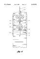
Referring now to FIG. 3, the structure of tube forming apparatus 100 for making the mineral insulated cable 10 is shown. In the tube making process, a flat metal strip 20 from a feed reel 22 is formed by one or more forming rolls, illustrated by forming rolls 24, into a generally cylindrical configuration. An anti-twist mechanism and seam guide 26 remove the twist induced in the formed metal strip during the forming process and align opposite linear sides of the formed metal strip with an electrode of an arc welder 28. A pair of closing rolls 30 complete the closing of the cylindrical configuration of the formed metal strip 20 such that the opposite sides thereof are in intimate contact with each other. At this juncture, the opposite edges of the metal strip 20 are welded to each other by the arc welder 28 to form the metal sheath 14.
Simultaneously, one or more wires 12 from a wire reel or reels 32 are guided into a fill tube 34 which extends into the seam-welded metal sheath 14 to a location at least three inches downstream of the welding head of the arc welder 28, as shown in FIG. 3. The fill tube 34 receives the mineral powder 16 from a hopper 36 which should be heated to a temperature of about 400° F. to exclude moisture. As more clearly shown in FIG. 4, the fill tube 34 has a head 38 having interconnected internal passages 40 and 42. Internal passage 40 has one end connected to the hopper 36 and the opposite end connected to internal passage 42. Internal passage 42 receives the wire or wires 12 from the wire reel 32. A wire guide 44 is provided at the opposite or lower end of the fill tube 34, which positions the wire or wires 12 relative to each other and to the internal walls of the metal sheath 14. Powder exit slots 46 and 48 are provided at the lower end of the fill tube 34 as shown, which allow the mineral powder to flow from the fill tube 34 into the metal sheath 14. To facilitate the flow of the mineral powder through the fill tube 34 and into the sheath 14, a vibrator 35 vibrates the fill tube continuously at a selected frequency, such as 60 cycles/sec. This vibrator initiates the compaction of the mineral powder in the sheath 14.
The structure of the fill tube 34 is discussed in greater detail in U.S. Pat. No. 5,479,690 issued to Hall, Jr. on Jan. 2, 1996.
The mineral insulated cable 10 consisting of the metal sheath 14 and enclosing one or more wires 12 is filled with a mineral medium 16 such as a ceramic oxide (e.g. magnesium oxide) either in powder or pelletized form which is subsequently granulated. (Other types of mineral or ceramic insulator or nonconducting material may be used, e.g. boron nitride, aluminum nitride, calcium sulfide and the like.) The cable 10 is then wound on a take-up spool 50. In one embodiment, the mineral insulated cable 10 may subsequently be overlayed with a second sheath 18 compatible with the tube-making apparatus discussed above. To reduce the diameter of the cable 10 to a desired size, it may be cold drawn, then annealed one or more times as discussed hereinafter. This reduction of the cable diameter also compacts and internally supports the cable within the metal sheath.
In the alternative to winding the mineral insulated cable 10 directly on the take-up spool 50 as described relative to FIG. 3, the cable 10, as it exits the tube forming apparatus 100 may be cold drawn through at least a first diameter reducing die 54 and annealed in an annealing oven 52, as shown in FIG. 5. The drawn cable 10 may further be drawn through at least a second diameter reducing die 58 and furnace 56 before being wound on a take-up spool. The process of cold drawing and annealing may be repeated as many times as required to reduce the diameter of the mineral insulated cable 10 to the desired size. The length of the annealing ovens 54,58 is selected so that the forming of the mineral insulated cable 10, the cold drawing and the annealing are one continuous process. Though the arrangement of FIG. 5 depicts the drawing and annealing steps to be in-line, it will be apparent to those of ordinary skill in the art that such steps may be undertaken separately in relative isolation from each other.
In the manufacturing process, it may be necessary to stop the tube forming apparatus 100 to replace or sharpen the electrode of the arc welder 28, to replace empty feed reel 22 or wire reel 22 with full reels of new material. To accommodate these stoppages, the arc welder 28, the closing rolls 30, and at least one set of forming rolls 24 may be mounted on a movable base 60 as shown in FIG. 6. Upon stoppage of the tube forming process for any reason, the base 60 may be displaced from its normal operation position linearly a predetermined distance to a stop position downstream of the stopped sheath 14, such that the electrode of the arc welder 28 overlays a previously welded portion of the welded seam 62. In the stopping of the tube-forming process, electrical power to the electrode of the arc welder 28 is turned off to prevent damage to the underlying welded tube. Upon restarting of the tube forming apparatus 100, the movable base 60 is slowly displaced from the stop position back to the normal operating position. As the base 60 is moved back to its normal operating position, the arc welder 28 is turned on and it will overweld the previous welded seam 62, then continue to weld the seam in a normal manner without any defects in the welded seam 62 due to the stoppage. The base 60 may be manually, electrically, pneumatically, or hydraulically moved as discussed in U.S. Pat. No. 5,346,116.
It has been found that the iron and iron oxide content of the mineral powder 16 used to fill the metal sheath 14 may be detrimental to the stability of a thermocouple element made using the above process. It further has been found that the current methods used by the manufacturers of the mineral powder to remove the iron and iron oxide contaminants is unsatisfactory. To further separate and remove the unwanted iron and iron oxide particles from the mineral powder 16, the separator 64 shown in FIG. 7 has been found to be very effective. The separator 64 has a durable, tear-resistant, stationary thin non-magnetic film such as a MYLAR® or a plastic (or rubber) film 66, approximately 1/1000 inches thick, draped over a rotating magnet drum 68. The top end of the film 66 is attached to a fixed upper structural member 70 such that the upper portion 72 of the film 66 is pitched at approximately 0-30° relative to the horizontal. The lower portion 74 of the fixed film 66 is attached to a lower stationary member 76 and extends at an angle of about 30° below a horizontal plane such that the lower stationary member 76 lies below the point of departure of the film from the drum. Mineral powder 16 stored in a hopper 78 flows from an exit slot 80 onto the stationary film 66 at a location offset from the axis of the rotating magnetic drum 68. The nonmagnetic powdered mineral particles will flow by gravity about the curved forward surface of film 66 and fall substantially vertically into a first container 82. The iron and iron oxide particles attracted to the rotating magnetic drum 68 will be deflected by the magnetic field into a second container 84. The magnetic drum 68 is made from a plurality of permanent magnets 86 approximately equally spaced about its periphery.
The particle separation process may be enhanced by reducing the first separated mineral powder in a reducing atmosphere (e.g., hydrogen, H--N mixtures, cracked ammonium, etc.) at an elevated temperature of approximately 1000° C. to reduce the iron oxides to metallic iron particles and water, then repeat the separation process using the separator 64 described above. Tests have shown that the iron and iron oxide content of the mineral powder was reduced from about 0.06% as originally received to about 0.04% after a first separation using the above-described separator and to about 0.03% after reduction in a hydrogen atmosphere and a second magnetic separation. (In this specification, all percentages are expressed as percent by weight.)
The process 200 of forming the mineral insulated cable 10 is recapitulated with reference to the flow diagram shown on FIG. 8. The process begins by the removal of the iron and iron oxide particles from the mineral powder as indicated by block 202. After removal of the iron and iron oxide particles, the mineral powder is heated, block 204, to remove any residual moisture. The process then continuously forms a partially closed tube from a metal strip as indicated by block 206. The partially closed tube is then passed through an anti-twist mechanism and alignment tool, block 208, to remove any twist in the partially formed tube during its formation and to align the edges of the partially formed tube with the electrode of the arc welder 28. The partially closed tube is then closed about a fill tube and welded closed, as indicated by block 210, to form a sheath. At least one wire and the purified mineral powder are inserted into the sheath through the fill tube to form the mineral insulated cable 10 as indicated by block 212. The mineral insulated tube 10 is then vibrated by one or more vibrators (preferably at about 60 cps) at a location downstream of the fill tube to initiate the compaction of the mineral powder in the sheath as indicated by block 214.
Subsequently, the cable 10 is cold drawn through a lubricated die as indicated in block 216, to reduce its diameter and further compact the mineral powder. A gear reduction motor driving a capstan pulls the cable 10 through the die and gathers the drawn cable thereon.
The drawn cable may subsequently be drawn through a single head wire drawing machine, block 218, to further reduce the diameter cable. The cable 10 is then annealed at approximately 1900° F., then air cooled to ambient temperature as indicated by block 220. The alternate steps of drawing and annealing, blocks 218 and 220 respectively are repeated until the mineral insulated cable 10 is reduced to a desired diameter as indicated by block 222.
To minimize the effects of weld defects on the performance of the mineral insulated cable 10, the process may include the additional step of applying a second sheath 18 over the mineral insulated cable 10 as indicated by block 224 on FIG. 9. Preferably, the welded seams of the first or inner sheath and the welded seam of the second or outer sheath are in opposite quadrants. Except for the addition of the second sheath, block 224, the process shown on FIG. 9 is identical to the process shown on and described with reference to FIG. 8.
The details of the process for separating the iron and iron oxide particles from the mineral powder 16 prior to filling the metal sheath 14 will be discussed relative to the flow diagram shown in FIG. 10. The process begins by rotating a magnetic drum shrouded by a stationary plastic film such as a thin MYLAR® film as indicated by block 226. A flow of mineral powder 16 is then directed onto an upper portion of the stationary plastic film at a location such that the mineral powder will flow by the force of gravity along the curved contour of the plastic film defined by the magnetic drum as indicated by block 228. The iron particles in the mineral powder will be attracted by the magnetic field of the rotating magnetic drum through the plastic film and will separate from the plastic film at a location different from the non-magnetic mineral powder. The non-magnetic powder, after the removal of the iron particles, is separately collected as indicated by block 230.
The separated non-magnetic mineral powder is then reduced in a hydrogen atmosphere at an elevated temperature (approximately 1000° C.) to reduce the iron oxides to metallic iron particles and water as indicated by block 232. A flow of the reduced mineral powder is then directed onto the stationary plastic film where the metallic iron particles resulting from the hydrogen reduction are removed from the flow of powder by the magnetic attraction of the rotating magnetic drum as indicated by block 234. Finally, the purified mineral powder is collected, block 236, and then heated, block 238, to drive out any moisture that may have been absorbed by the mineral powder from the atmosphere. The purified and demoisturized mineral powder is subsequently used for filling the sheath as discussed relative to FIG. 3.
It is recognized that those skilled in the art may make certain changes or improvements to the process for making mineral insulated cables within the scope of the appended claims. It is not intended to limit the invention to the disclosed process or the tube making apparatus specifically shown in the drawings and discussed in the specification.

Claims (10)

What is claimed Is:
1. A method for making a mineral insulated cable comprising;
magnetically separating magnetic particles from a mineral medium to produce a once purified mineral medium containing iron oxide particles;
reducing the once purified mineral medium in a hydrogen atmosphere to convert the iron oxide particles to iron particles;
magnetically separating the iron particles from the reduced mineral medium to produce a purified mineral medium;
forming a seam-welded metal sheath from a metal strip; and
inserting at least one wire and the purified mineral medium into the seam-welded metal sheath to produce a length of mineral insulated cable.
2. The method of claim 1 further including after said step of inserting, the following steps:
cold drawing the mineral insulated cable to reduce its diameter;
annealing the drawn mineral insulated cable as it passes through at least one annealing oven; and
repeating the steps of cold drawing and annealing said mineral insulated cable until the diameter of said mineral insulated cable has been reduced to a desired size.
3. The method of claim 1 including forming a second metal sheath over said first metal sheath.
4. The method of claim 3 wherein the first and second sheaths have welded seams and wherein the welded seam of the second sheath is located in a quadrant opposite the welded seam of the first sheath.
5. The method of claim 1 wherein the step of forming a seam-welded metal sheath imparts a twist in the metal sheath, said step further including the steps of:
removing the twist imparted to the metal sheath prior to welding the seam; and
aligning the edges of the metal strip in relation to an arc welder electrode prior to welding the seam.
6. The method of claim 1 wherein said at least one wire and said purified mineral powder are inserted into the seam-welded sheath by a fill tube at a location downstream of an arc welder, the method further including the step of vibrating the mineral insulated cable at a location downstream of the fill tube to initiate compaction of the mineral powder.
7. The method of claim 1 wherein the step of forming a seam-welded metal sheath comprises the step of continuously forming the seam-welded sheath.
8. The method of claim 1 wherein the step of inserting at least one wire comprises the step of continuously inserting the at least one wire so that a continuous length of mineral insulated cable is produced thereby.
9. The method of claim 1 wherein said second step of magnetically separating comprises the steps of:
rotating a magnetic drum shrouded by a stationary film; and
directing a flow of the reduced mineral medium onto an upper portion of the stationary film at a location such that the mineral medium will flow by the force of gravity along a contour formed in the stationary film by the rotating magnetic drum to magnetically separate iron particles from the mineral medium to produce the purified mineral medium.
10. The method of claim 9 further including the step of heating the mineral medium to remove absorbed moisture.
US09/193,531 1998-11-17 1998-11-17 Method for making mineral insulated cable Expired - Fee Related US6119922A (en)

Priority Applications (3)

Application Number Priority Date Filing Date Title
US09/193,531 US6119922A (en) 1998-11-17 1998-11-17 Method for making mineral insulated cable
PCT/US1999/025779 WO2000029117A1 (en) 1998-11-17 1999-11-02 A method for making mineral insulated cable
AU13384/00A AU1338400A (en) 1998-11-17 1999-11-02 A method for making mineral insulated cable

Applications Claiming Priority (1)

Application Number Priority Date Filing Date Title
US09/193,531 US6119922A (en) 1998-11-17 1998-11-17 Method for making mineral insulated cable

Publications (1)

Publication Number Publication Date
US6119922A true US6119922A (en) 2000-09-19

Family

ID=22714002

Family Applications (1)

Application Number Title Priority Date Filing Date
US09/193,531 Expired - Fee Related US6119922A (en) 1998-11-17 1998-11-17 Method for making mineral insulated cable

Country Status (3)

Country Link
US (1) US6119922A (en)
AU (1) AU1338400A (en)
WO (1) WO2000029117A1 (en)

Cited By (5)

* Cited by examiner, † Cited by third party
Publication number Priority date Publication date Assignee Title
US20100264568A1 (en) * 2007-11-29 2010-10-21 Corning Incorporated System and method for forming ceramic precursor material for thin-walled ceramic honeycomb structures
US20120298398A1 (en) * 2009-12-09 2012-11-29 Pruftech Gmbh Cable comprising indicator material for detecting damage control
CN102982898A (en) * 2012-11-20 2013-03-20 中国科学院等离子体物理研究所 Method for manufacturing magnesium oxide mineral insulated cable with cold extrusion reducing forming method
US20210251049A1 (en) * 2020-02-07 2021-08-12 Thermocoax Mineral-insulated shielded cable for ultra high temperatures, heating element and transmission cable, application and manufacturing method
CN114360811A (en) * 2021-11-23 2022-04-15 浙江元通线缆制造有限公司 Production process for continuously producing rigid mineral cable

Families Citing this family (1)

* Cited by examiner, † Cited by third party
Publication number Priority date Publication date Assignee Title
CN110707614B (en) * 2019-09-19 2020-11-13 宁波东方电缆股份有限公司 Method for repairing flexible mineral insulated cable with metal outer sheath

Citations (14)

* Cited by examiner, † Cited by third party
Publication number Priority date Publication date Assignee Title
US3327852A (en) * 1964-12-18 1967-06-27 Sala Maskinfabriks Aktiebolag Drum type magnetic separator
US3737822A (en) * 1970-06-10 1973-06-05 Magnetics Int Inc Magnetic separator
US4420881A (en) * 1980-09-23 1983-12-20 Les Cables De Lyon Method of manufacturing a preform for mineral-insulated electric cable
US4512827A (en) * 1981-09-21 1985-04-23 Associated Electrical Industries Limited Method of manufacturing mineral insulated electric cable and like elements
US4629110A (en) * 1984-10-03 1986-12-16 Werner Holmgren Method for manufacturing powder-filled tubular welding electrodes and a device for performing the method
US4739155A (en) * 1986-01-16 1988-04-19 Pyrotenax Of Canada Ltd. Mineral insulated parallel-type heating cables
US5092986A (en) * 1988-04-25 1992-03-03 Steinert Elektromagnetbau Gmbh Magnetic separator
JPH0646869A (en) * 1992-07-31 1994-02-22 Canon Inc Method for biodegrading furan compound and production of 2-furancarboxylic acid
US5328086A (en) * 1993-08-20 1994-07-12 Hoskins Manufacturing Co. Mechanism and method for removing twists in a tube forming machine
US5346116A (en) * 1993-06-24 1994-09-13 Hall Jr Bertie F Machine for forming a metal strip into a tubular form having a stop-restart displacement mechanism
US5453599A (en) * 1994-02-14 1995-09-26 Hoskins Manufacturing Company Tubular heating element with insulating core
US5464485A (en) * 1993-07-01 1995-11-07 Hoskins Manufacturing Co. Coaxial thermoelements and thermocouples made from coaxial thermoelements
US5479690A (en) * 1993-12-01 1996-01-02 Hoskins Manufacturing Company Tube making mechanism having a fill tube for depositing a ceramic powder into the tube as it is being made
US5660805A (en) * 1989-10-31 1997-08-26 E. I. Du Pont De Nemours And Company Method for beneficiating titanium-bearing material containing iron

Patent Citations (14)

* Cited by examiner, † Cited by third party
Publication number Priority date Publication date Assignee Title
US3327852A (en) * 1964-12-18 1967-06-27 Sala Maskinfabriks Aktiebolag Drum type magnetic separator
US3737822A (en) * 1970-06-10 1973-06-05 Magnetics Int Inc Magnetic separator
US4420881A (en) * 1980-09-23 1983-12-20 Les Cables De Lyon Method of manufacturing a preform for mineral-insulated electric cable
US4512827A (en) * 1981-09-21 1985-04-23 Associated Electrical Industries Limited Method of manufacturing mineral insulated electric cable and like elements
US4629110A (en) * 1984-10-03 1986-12-16 Werner Holmgren Method for manufacturing powder-filled tubular welding electrodes and a device for performing the method
US4739155A (en) * 1986-01-16 1988-04-19 Pyrotenax Of Canada Ltd. Mineral insulated parallel-type heating cables
US5092986A (en) * 1988-04-25 1992-03-03 Steinert Elektromagnetbau Gmbh Magnetic separator
US5660805A (en) * 1989-10-31 1997-08-26 E. I. Du Pont De Nemours And Company Method for beneficiating titanium-bearing material containing iron
JPH0646869A (en) * 1992-07-31 1994-02-22 Canon Inc Method for biodegrading furan compound and production of 2-furancarboxylic acid
US5346116A (en) * 1993-06-24 1994-09-13 Hall Jr Bertie F Machine for forming a metal strip into a tubular form having a stop-restart displacement mechanism
US5464485A (en) * 1993-07-01 1995-11-07 Hoskins Manufacturing Co. Coaxial thermoelements and thermocouples made from coaxial thermoelements
US5328086A (en) * 1993-08-20 1994-07-12 Hoskins Manufacturing Co. Mechanism and method for removing twists in a tube forming machine
US5479690A (en) * 1993-12-01 1996-01-02 Hoskins Manufacturing Company Tube making mechanism having a fill tube for depositing a ceramic powder into the tube as it is being made
US5453599A (en) * 1994-02-14 1995-09-26 Hoskins Manufacturing Company Tubular heating element with insulating core

Cited By (8)

* Cited by examiner, † Cited by third party
Publication number Priority date Publication date Assignee Title
US20100264568A1 (en) * 2007-11-29 2010-10-21 Corning Incorporated System and method for forming ceramic precursor material for thin-walled ceramic honeycomb structures
US20120298398A1 (en) * 2009-12-09 2012-11-29 Pruftech Gmbh Cable comprising indicator material for detecting damage control
US9472321B2 (en) * 2009-12-09 2016-10-18 Pruftech Gmbh Cable comprising indicator material for detecting damage control
CN102982898A (en) * 2012-11-20 2013-03-20 中国科学院等离子体物理研究所 Method for manufacturing magnesium oxide mineral insulated cable with cold extrusion reducing forming method
CN102982898B (en) * 2012-11-20 2015-06-03 中国科学院等离子体物理研究所 Method for manufacturing magnesium oxide mineral insulated cable with cold extrusion reducing forming method
US20210251049A1 (en) * 2020-02-07 2021-08-12 Thermocoax Mineral-insulated shielded cable for ultra high temperatures, heating element and transmission cable, application and manufacturing method
CN114360811A (en) * 2021-11-23 2022-04-15 浙江元通线缆制造有限公司 Production process for continuously producing rigid mineral cable
CN114360811B (en) * 2021-11-23 2024-03-08 浙江元通线缆制造有限公司 Production process for continuously producing rigid mineral cables

Also Published As

Publication number Publication date
AU1338400A (en) 2000-06-05
WO2000029117A1 (en) 2000-05-25

Similar Documents

Publication Publication Date Title
US2529812A (en) Method of and apparatus for arc welding
US6119922A (en) Method for making mineral insulated cable
US3834002A (en) Method of manufacturing a composite metal sheathed welding electrode
JP2007222941A (en) Method for manufacturing welded pipe filled with powder, for example, flux cored welding wire
EP0003370A1 (en) Method for the continuous manufacture of a powder-filled welded tube
JPH0244639B2 (en)
JPH0328765B2 (en)
US2146430A (en) Welding apparatus
US2697769A (en) Aluminum sheathed cable and method of making
US3209119A (en) Method and apparatus for welding
US1965331A (en) Arc welding apparatus
CN114360811B (en) Production process for continuously producing rigid mineral cables
US20040140293A1 (en) Method and device for connecting minute joint metal, and composite tape for connecting minute joint metal
US4319118A (en) Method of welding tantalum lead wires to tantalum capacitor anodes
JPS6133781A (en) Method of variously using copper wire in resistance seam welding
US2446598A (en) Automatic arc welding apparatus
US1287774A (en) Apparatus for electric welding.
JP3231440B2 (en) Manufacturing method of flux cored wire for welding
US1840600A (en) Method of and apparatus for arc-welding
JPS6241808B2 (en)
US3210592A (en) Frame grids
JPH01127231A (en) Wire waste disposal device for wire electric discharge machine
JPH0976093A (en) Manufacture of powder filling tube and its device
JP3199929B2 (en) Manufacturing method of powder filled tube
JPH06312293A (en) Manufacture of tube for filling granular material

Legal Events

Date Code Title Description
AS Assignment

Owner name: HOSKINS MANUFACTURING COMPANY, MICHIGAN

Free format text: ASSIGNMENT OF ASSIGNORS INTEREST;ASSIGNOR:HALL, BERTIE FORREST, JR.;REEL/FRAME:009600/0770

Effective date: 19981117

AS Assignment

Owner name: CONCEPT ALLOYS, L.L.C., MICHIGAN

Free format text: ASSIGNMENT OF ASSIGNORS INTEREST;ASSIGNOR:HOSKINS MANUFACTURING COMPANY;REEL/FRAME:012513/0090

Effective date: 20011218

REMI Maintenance fee reminder mailed
AS Assignment

Owner name: HOSKINS ALLOYS, L.L.C., MICHIGAN

Free format text: CHANGE OF NAME;ASSIGNOR:CONCEPT ALLOYS, L.L.C.;REEL/FRAME:015642/0864

Effective date: 20030228

LAPS Lapse for failure to pay maintenance fees
FP Lapsed due to failure to pay maintenance fee

Effective date: 20040919

STCH Information on status: patent discontinuation

Free format text: PATENT EXPIRED DUE TO NONPAYMENT OF MAINTENANCE FEES UNDER 37 CFR 1.362